Embed Size (px)
Citation preview
Bauhaus-Universit ät
W eimar
Fa
culty
of
Civ
il E
ngin
ee
rin
g
Labora
tory
of S
oil
Mechanic
s
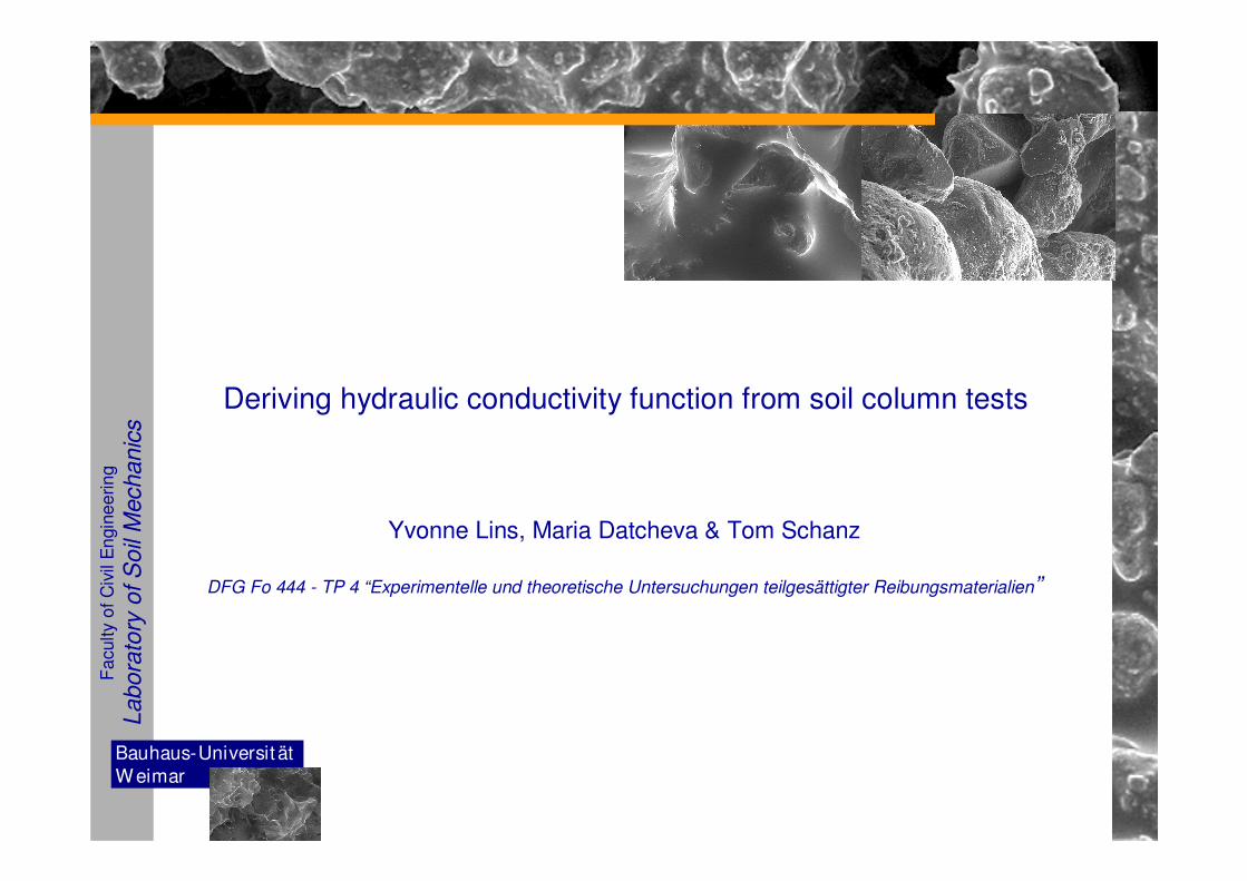
Deriving hydraulic conductivity function from soil column tests
Yvonne Lins, Maria Datcheva & Tom Schanz
DFG Fo 444 - TP 4 “Experimentelle und theoretische Untersuchungen teilgesättigter Reibungsmaterialien”
Bauhaus-Universit ät
W eimar
Fa
culty
of
Civ
il E
ngin
ee
rin
g
Labora
tory
of S
oil
Mechanic
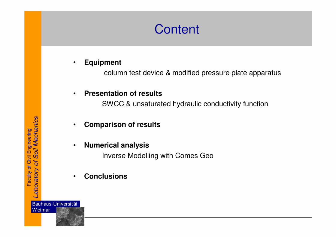
sContent
• Equipment
column test device & modified pressure plate apparatus
• Presentation of results
SWCC & unsaturated hydraulic conductivity function
• Comparison of results
• Numerical analysis
Inverse Modelling with Comes Geo
• Conclusions
Bauhaus-Universit ät
W eimar
Fa
culty
of
Civ
il E
ngin
ee
rin
g
Labora
tory
of S
oil
Mechanic
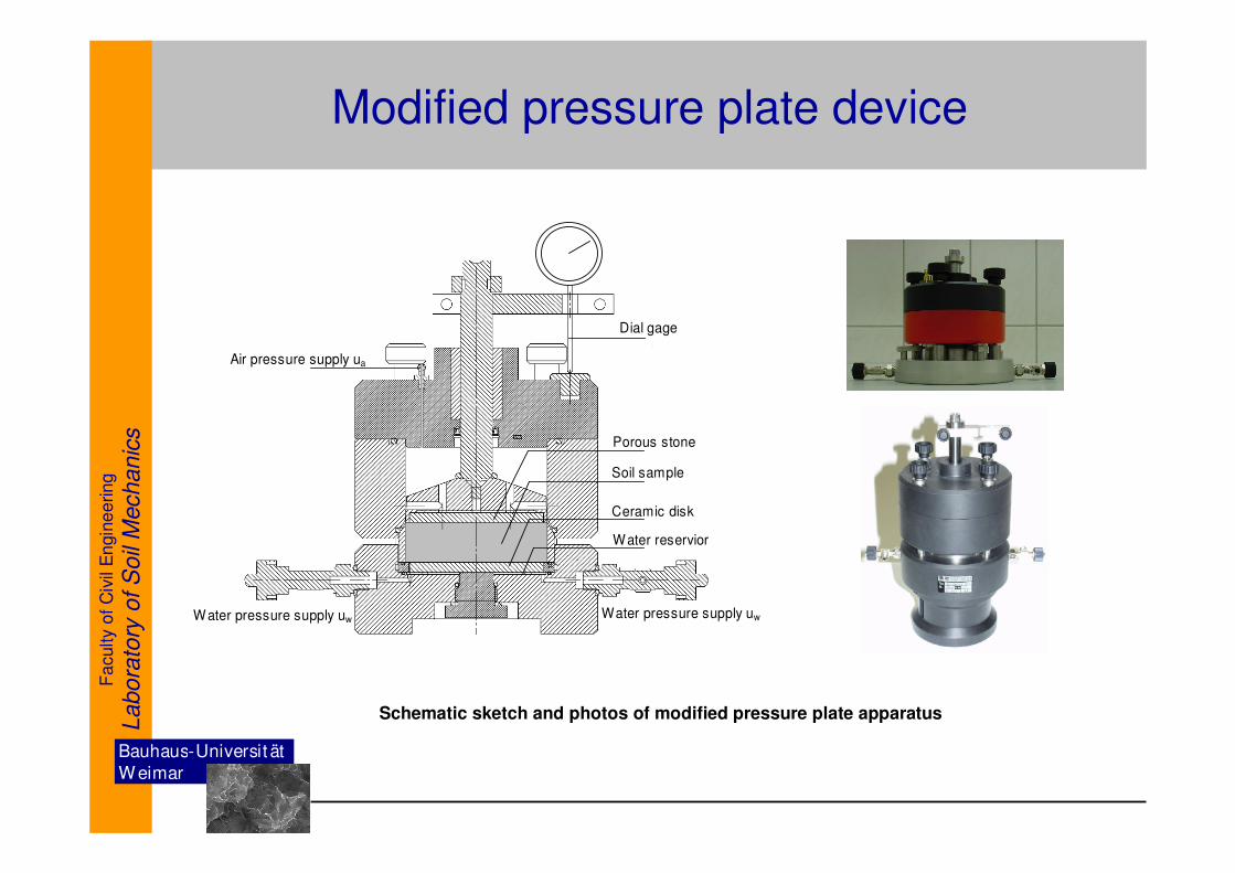
sModified pressure plate device
Schematic sketch and photos of modified pressure plate apparatus
Porous stone
Soil sample
Ceramic disk
Water reservior
Dial gage
Air pressure supply ua
Water pressure supply uwWater pressure supply uw
Bauhaus-Universit ät
W eimar
Fa
culty
of
Civ
il E
ngin
ee
rin
g
Labora
tory
of S
oil
Mechanic
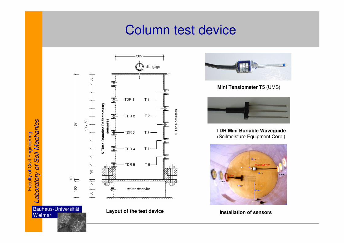
sColumn test device
305
67
10
0
10
5 0
90
10
x 5
0
80
50
TDR 5
TDR 4
TDR 3
TDR 2
TDR 15
Tim
e D
om
ain
e R
efl
ec
tom
etr
y
se
ns
ore
s
5 T
en
sio
me
ters
T 5
T 4
T 2
T 3
T 1
water reservior
dial gage
Layout of the test device
Mini Tensiometer T5 (UMS)
TDR Mini Buriable Waveguide (Soilmoisture Equipment Corp.)
Installation of sensors
Bauhaus-Universit ät
W eimar
Fa
culty
of
Civ
il E
ngin
ee
rin
g
Labora
tory
of S
oil
Mechanic
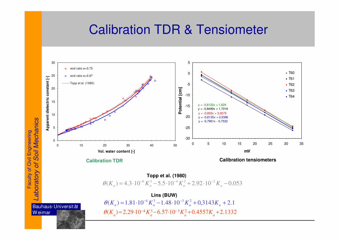
sCalibration TDR & Tensiometer
1.23143,01048.11081.1)( 2334 ++⋅−⋅= −−aaaa KKKKθ
1332.24557.01057.61029.2)( 2334 ++⋅−⋅= −−aaaa
KKKKθ
053.01092.2105.5103.4)( 22436 −⋅+⋅−⋅= −−−aaaa KKKKθ
Topp et al. (1980)
Lins (BUW)
y = -0,859x + 3,0075
y = -0,8122x + 1,624
y = -0,8499x + 1,7018
y = -0,8135x + 0,9386
y = -0,7961x - 0,7532
-30
-25
-20
-15
-10
-5
0
5
0 5 10 15 20 25 30 35
mV
Po
ten
tial [c
m]
T60
T61
T62
T63
T64
0
5
10
15
20
25
30
0 10 20 30 40 50
Vol. water content [-]
Ap
pa
ren
t d
iele
ctr
ic c
on
sta
nt
[-]
void ratio e=0.75
void ratio e=0.97
Topp et al. (1980)
Calibration TDR Calibration tensiometers
Bauhaus-Universit ät
W eimar
Fa
culty
of
Civ
il E
ngin
ee
rin
g
Labora
tory
of S
oil
Mechanic
s
Unsaturated hydraulic conductivity by using statistical model
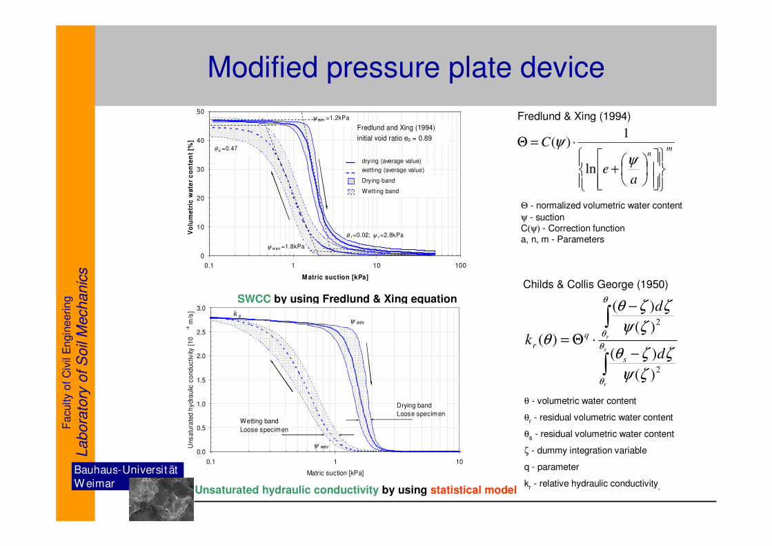
Modified pressure plate device
mn
ae
C
+
⋅=Θ
ψ
ψ
ln
1)(
SWCC by using Fredlund & Xing equation
0.0
0.5
1.0
1.5
2.0
2.5
3.0
0.1 1 10
Matric suction [kPa]
Un
sa
tura
ted
hy
dra
ulic
co
nd
uc
tivity
[1
0
-4 m
/s]
Drying band
Loose specimenWetting band
Loose specimen
ψ aev
ψ wev
k s
0
10
20
30
40
50
0.1 1 10 100
M atric suction [kPa]
Vo
lum
etr
ic w
ate
r c
on
ten
t [%
]
Fredlund and Xing (1994)
initial void ratio e0 = 0.89
drying (average value)
wetting (average value)
Drying band
Wetting band
ψ aev =1.2kPa
ψ w ev =1.8kPa
θ r =0.02; ψ r =2.8kPa
θ s =0.47
∫
∫
−
−
⋅Θ=s
r
r
d
d
k
s
q
r θ
θ
θ
θ
ζψ
ζζθ
ζψ
ζζθ
θ
2
2
)(
)(
)(
)(
)(
Θ - normalized volumetric water content
ψ - suctionC(ψ) - Correction functiona, n, m - Parameters
θ - volumetric water content
θr - residual volumetric water content
θs - residual volumetric water content
ζ - dummy integration variable
q - parameter
kr - relative hydraulic conductivity,
Childs & Collis George (1950)
Fredlund & Xing (1994)
Bauhaus-Universit ät
W eimar
Fa
culty
of
Civ
il E
ngin
ee
rin
g
Labora
tory
of S
oil
Mechanic
s
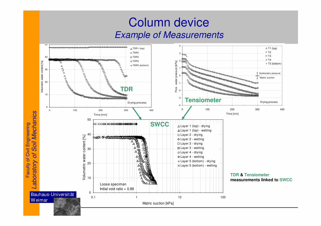
Column deviceExample of Measurements
0
10
20
30
40
50
0.1 1 10 100
Matric suction [kPa]
Vo
lum
etr
ic w
ate
r c
on
ten
t [%
]
Layer 1 (top) - drying
Layer 1 (top) - wetting
Layer 2 - drying
Layer 2 - wetting
Layer 3 - drying
Layer 3 - wetting
Layer 4 - drying
Layer 4 - wetting
Layer 5 (bottom) - drying
Layer 5 (bottom) - wetting
Loose specimen
Initial void ratio = 0.89
0
10
20
30
40
50
0 100 200 300 400
Time [min]
Volu
metr
ic w
ate
r conte
nt [%
]
TDR1 (top)
TDR2
TDR3
TDR4
TDR5 (bottom)
Drying process-4
-3
-2
-1
0
1
2
3
4
0 100 200 300 400
Time [min]
Pore
- w
ate
r p
res
su
re [k
Pa
]
T1 (top)
T2
T3
T4
T5 (bottom)
Matric suction
Hydrostatic pressure
Drying process
SWCC
TDR & Tensiometermeasurements linked to SWCC
Tensiometer
TDR
Bauhaus-Universit ät
W eimar
Fa
culty
of
Civ
il E
ngin
ee
rin
g
Labora
tory
of S
oil
Mechanic
s
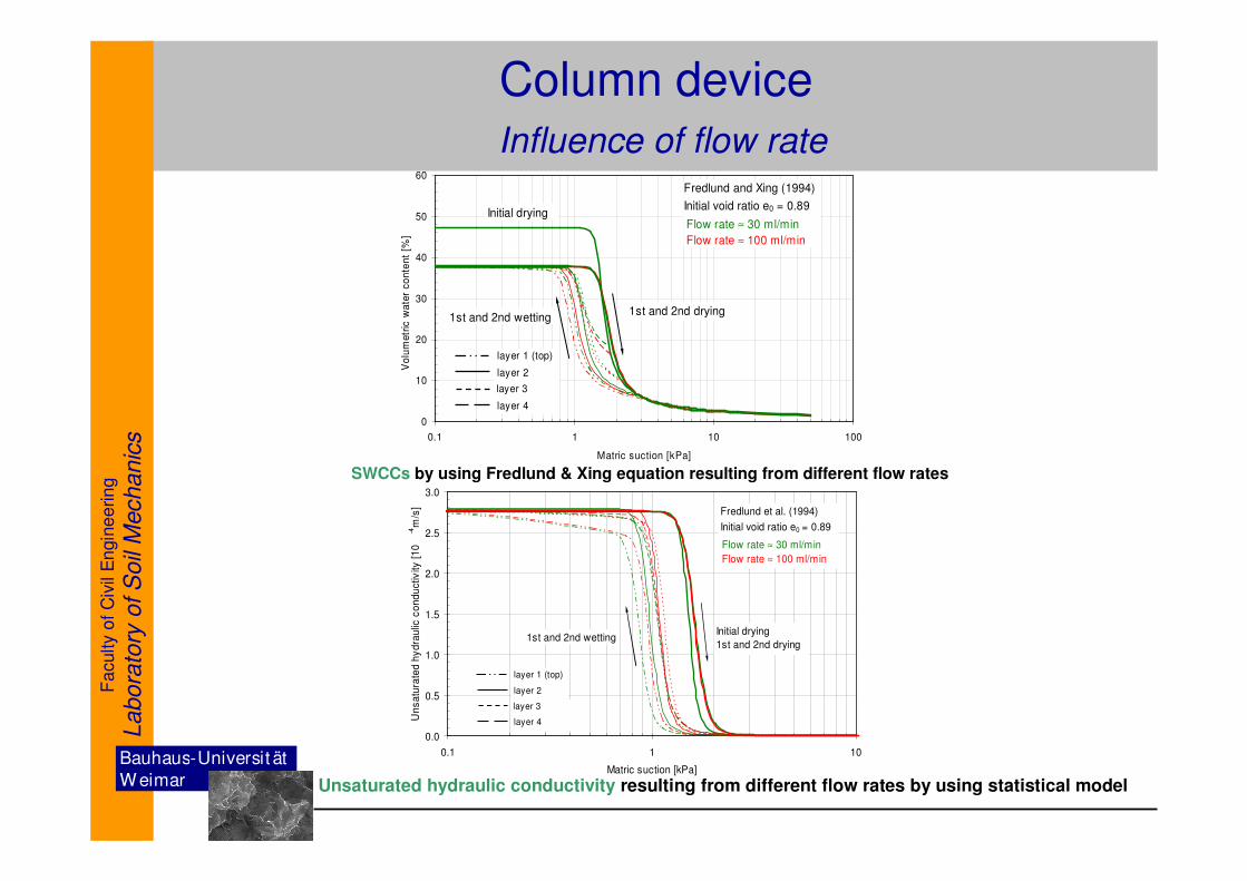
Column device
Influence of flow rate
SWCCs by using Fredlund & Xing equation resulting from different flow rates
0
10
20
30
40
50
60
0.1 1 10 100
Matric suction [kPa]
Vo
lum
etr
ic w
ate
r co
nte
nt
[%]
layer 1 (top)
layer 2
layer 3
layer 4
Initial drying
1st and 2nd drying1st and 2nd wetting
Flow rate ≈ 30 ml/min
Flow rate ≈ 100 ml/min
Fredlund and Xing (1994)
Initial void ratio e0 = 0.89
0.0
0.5
1.0
1.5
2.0
2.5
3.0
0.1 1 10
Matric suction [kPa]
Un
sa
tura
ted h
yd
rau
lic c
on
du
ctiv
ity [
10
-4
m/s
]
layer 1 (top)
layer 2
layer 3
layer 4
Initial drying
1st and 2nd drying1st and 2nd wetting
Flow rate ≈ 30 ml/min
Flow rate ≈ 100 ml/min
Fredlund et al. (1994)
Initial void ratio e0 = 0.89
Unsaturated hydraulic conductivity resulting from different flow rates by using statistical model
Bauhaus-Universit ät
W eimar
Fa
culty
of
Civ
il E
ngin
ee
rin
g
Labora
tory
of S
oil
Mechanic
s
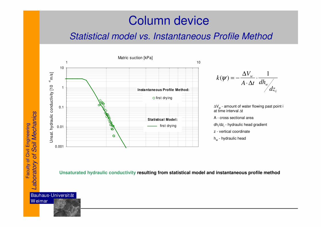
Column device
Statistical model vs. Instantaneous Profile Method
0.001
0.01
0.1
1
10
1 10
Matric suction [kPa]
Uns
at.
hy
dra
ulic
co
nd
uc
tivity
[1
0-4
m/s
]
first drying
first drying
Instantaneous Profile Method:
Statistical Model:
Unsaturated hydraulic conductivity resulting from statistical model and instantaneous profile method
i
w
w
dzdhtA
Vk
1)( ⋅
∆⋅
∆−=ψ
∆Vw - amount of water flowing past point i at time interval ∆t
A - cross sectional area
dhi/dzi - hydraulic head gradient
z - vertical coordinate
hw - hydraulic head
Bauhaus-Universit ät
W eimar
Fa
culty
of
Civ
il E
ngin
ee
rin
g
Labora
tory
of S
oil
Mechanic
s
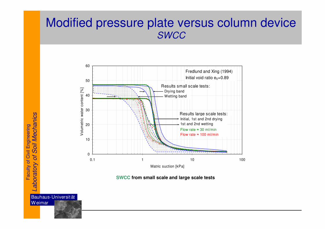
Modified pressure plate versus column deviceSWCC
SWCC from small scale and large scale tests
0
10
20
30
40
50
60
0.1 1 10 100
Matric suction [kPa]
Vo
lum
etr
ic w
ate
r c
on
ten
t [%
]
Fredlund and Xing (1994)
Initial void ratio e0=0.89
Flow rate ≈ 30 ml/min
Flow rate ≈ 100 ml/min
Results small scale tests: Drying band
Wetting band
Results large scale tests:Initial, 1st and 2nd drying
1st and 2nd wetting
Bauhaus-Universit ät
W eimar
Fa
culty
of
Civ
il E
ngin
ee
rin
g
Labora
tory
of S
oil
Mechanic
s
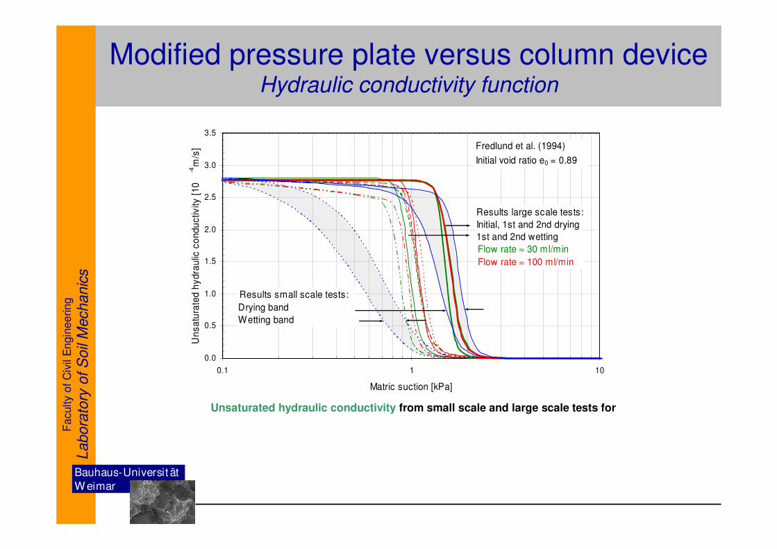
Unsaturated hydraulic conductivity from small scale and large scale tests for
Modified pressure plate versus column deviceHydraulic conductivity function
0.0
0.5
1.0
1.5
2.0
2.5
3.0
3.5
0.1 1 10
Matric suction [kPa]
Un
sa
tura
ted
hy
dra
ulic
co
nd
uc
tivity
[1
0
-4m
/s] Fredlund et al. (1994)
Initial void ratio e0 = 0.89
Flow rate ≈ 30 ml/min
Flow rate ≈ 100 ml/min
Results small scale tests:
Drying band
Wetting band
Results large scale tests:
Initial, 1st and 2nd drying
1st and 2nd wetting
Bauhaus-Universit ät
W eimar
Fa
culty
of
Civ
il E
ngin
ee
rin
g
Labora
tory
of S
oil
Mechanic
s
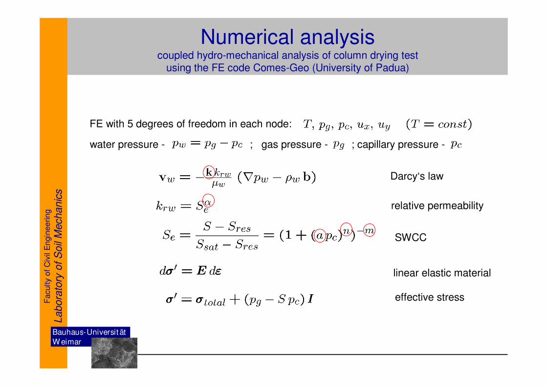
Numerical analysiscoupled hydro-mechanical analysis of column drying test
using the FE code Comes-Geo (University of Padua)
FE with 5 degrees of freedom in each node:
water pressure - ; gas pressure - ; capillary pressure -
Darcy‘s law
relative permeability
SWCC
linear elastic material
effective stress
Bauhaus-Universit ät
W eimar
Fa
culty
of
Civ
il E
ngin
ee
rin
g
Labora
tory
of S
oil
Mechanic
s
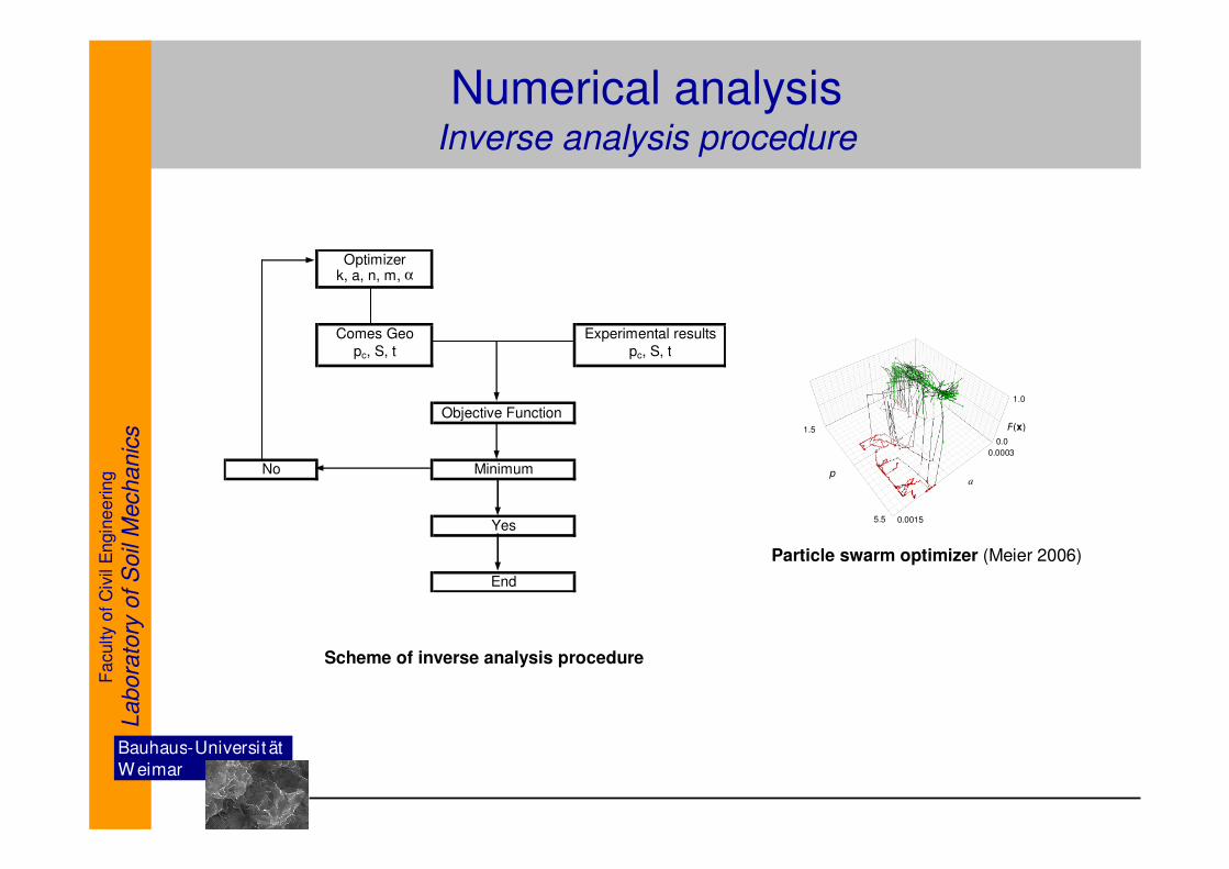
Numerical analysisInverse analysis procedure
Optimizerk, a, n, m, α
Comes Geo Experimental results
pc, S, t pc, S, t
Objective Function
No Minimum
Yes
End
Scheme of inverse analysis procedure
a p
1.5
5.5 0.0015
0.0003
F(x)
1.0
0.0
Particle swarm optimizer (Meier 2006)
Bauhaus-Universit ät
W eimar
Fa
culty
of
Civ
il E
ngin
ee
rin
g
Labora
tory
of S
oil
Mechanic
s
-4
-3
-2
-1
0
1
2
3
4
0 50 100 150 200 250 300
Time [min]
Pre
ssu
re h
ea
d [
kP
a]
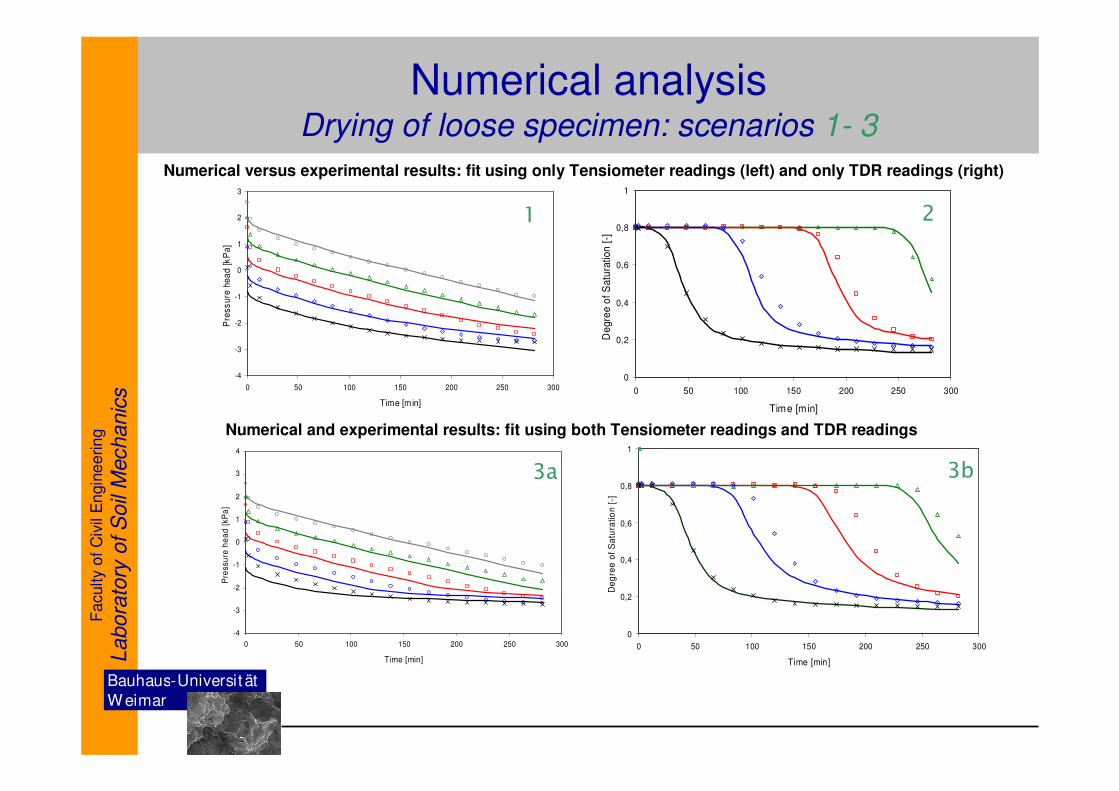
Numerical analysisDrying of loose specimen: scenarios 1- 3
-4
-3
-2
-1
0
1
2
3
0 50 100 150 200 250 300
Time [m in]
Pre
ss
ure
he
ad
[k
Pa
]
0
0,2
0,4
0,6
0,8
1
0 50 100 150 200 250 300
Time [min]
De
gre
e o
f S
atu
ration
[-]
Numerical versus experimental results: fit using only Tensiometer readings (left) and only TDR readings (right)
0
0,2
0,4
0,6
0,8
1
0 50 100 150 200 250 300
Time [min]
De
gre
e o
f S
atu
ratio
n [
-]
Numerical and experimental results: fit using both Tensiometer readings and TDR readings
1 2
3a 3b
Bauhaus-Universit ät
W eimar
Fa
culty
of
Civ
il E
ngin
ee
rin
g
Labora
tory
of S
oil
Mechanic
s
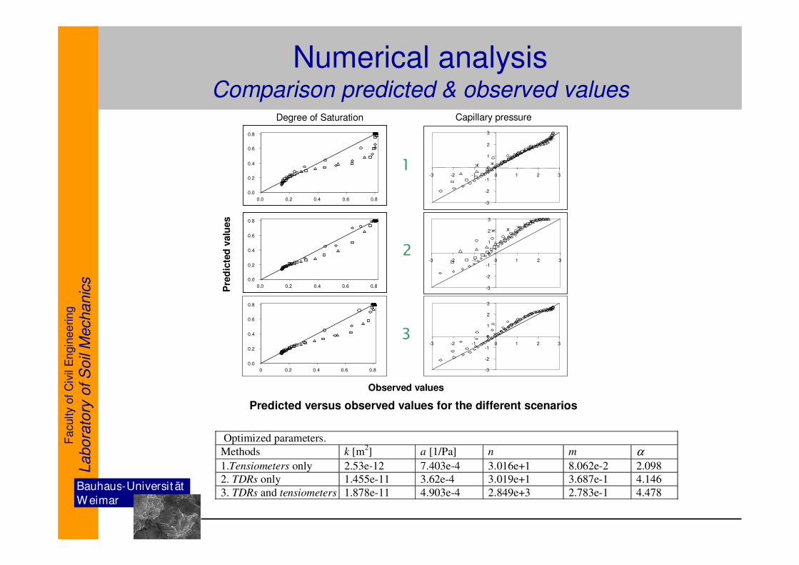
Numerical analysisComparison predicted & observed values
1
2
3
Predicted versus observed values for the different scenarios
Pre
dic
ted
valu
es
Observed values
Degree of Saturation Capillary pressure
0.0
0.2
0.4
0.6
0.8
0.0 0.2 0.4 0.6 0.8-3
-2
-1
0
1
2
3
-3 -2 -1 0 1 2 3
0.0
0.2
0.4
0.6
0.8
0.0 0.2 0.4 0.6 0.8 -3
-2
-1
0
1
2
3
-3 -2 -1 0 1 2 3
0.0
0.2
0.4
0.6
0.8
0 0.2 0.4 0.6 0.8 -3
-2
-1
0
1
2
3
-3 -2 -1 0 1 2 3
Optimized parameters.
Methods k [m2] a [1/Pa] n m α
1.Tensiometers only 2.53e-12 7.403e-4 3.016e+1 8.062e-2 2.098
2. TDRs only 1.455e-11 3.62e-4 3.019e+1 3.687e-1 4.146
3. TDRs and tensiometers 1.878e-11 4.903e-4 2.849e+3 2.783e-1 4.478
Bauhaus-Universit ät
W eimar
Fa
culty
of
Civ
il E
ngin
ee
rin
g
Labora
tory
of S
oil
Mechanic
s
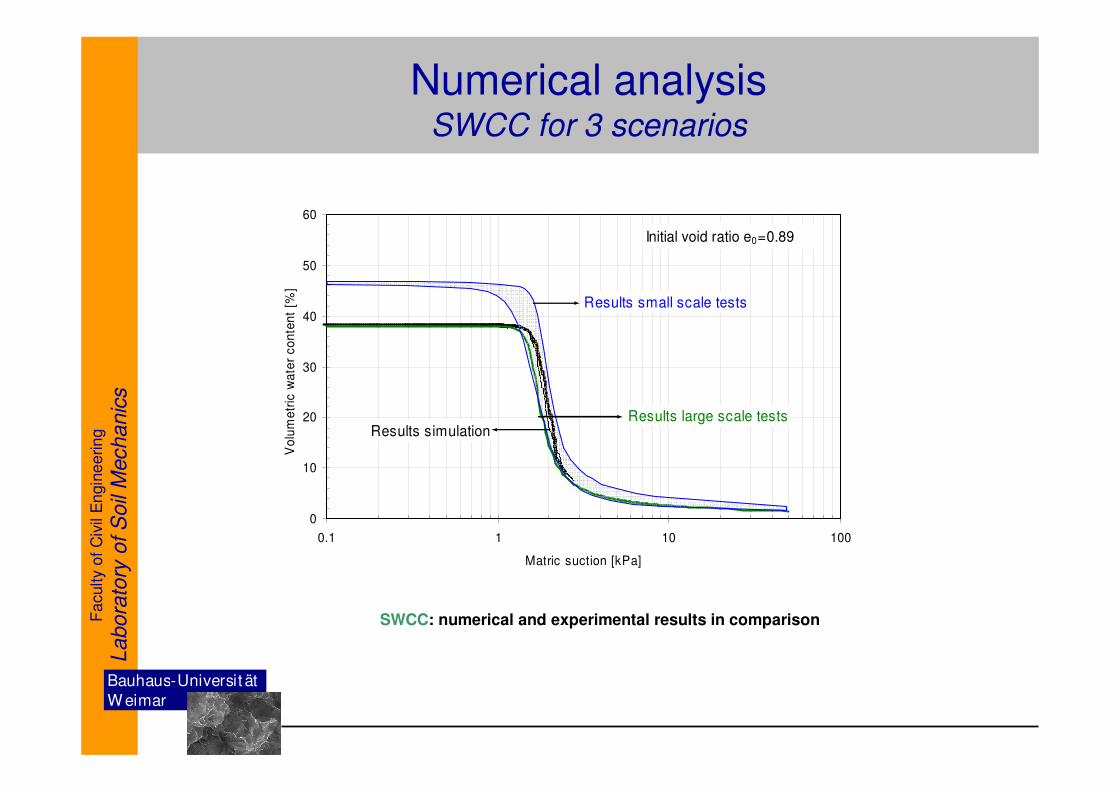
Numerical analysisSWCC for 3 scenarios
SWCC: numerical and experimental results in comparison
0
10
20
30
40
50
60
0.1 1 10 100
Matric suction [kPa]
Vo
lum
etr
ic w
ate
r co
nte
nt
[%]
Results large scale tests
Initial void ratio e0=0.89
Results small scale tests
Results simulation
Bauhaus-Universit ät
W eimar
Fa
culty
of
Civ
il E
ngin
ee
rin
g
Labora
tory
of S
oil
Mechanic
s
Summary & conclusions
We study the hydraulic behavior of unsaturated granular material in the case of Hostun sand.
New experimental devices were developed, a modified pressure plate apparatus and a column type device.
SWCC & hydraulic conductivity function were established for loose specimen under variable loading path directions utilizing steady state & transient method.
SWCC & hydraulic conductivity function for Hostun sand takes place in a narrow range of suction.
Significant effect of hysteresis was found for loose specimen in the drying and wetting curves
of SWCC.
Experiments carried out under steady state & transient method show similar behavior regarding SWCC and hydraulic conductivity function.
Inverse analysis of drying cycle of sand column test results was performed in different scenarios.
Bauhaus-Universit ät
W eimar
Fa
culty
of
Civ
il E
ngin
ee
rin
g
Labora
tory
of S
oil
Mechanic
sComes-Geo: Governing Equations
1. Equation of mass balance of the dry air
2. Equation of mass balance of the liquid
3. Enthalpy balance equation for the whole media
4. Linear momentum balance equation for the whole media
5. Solid mass conservation equation
6. The balance equations 1-5 are completed by an appropriate set of constitutiveand state equations (slide 12)
Formulation of the coupled problem is in


![01 % ./ ˝ +,- ˜ 7 : ˙ % 8%9 ) 7 /research.iaun.ac.ir/pd/lachinani/pdfs/UploadFile_2009.pdfSoil Permeability & Seepage. ... Hydraulic conductivity “permeability” [cm/s] Since](https://img.pdfslide.tips/doc/110x75/5e95b08b15b028107a02f7c0/01-oe-7-89-7-soil-permeability-seepage-hydraulic.jpg)