Embed Size (px)
Citation preview

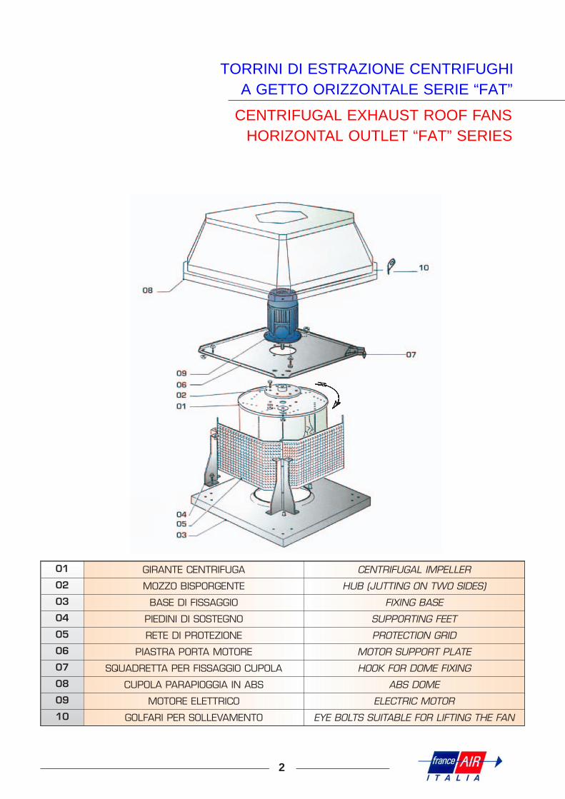
TORRINI DI ESTRAZIONE CENTRIFUGHIA GETTO ORIZZONTALE SERIE “FAT”
CENTRIFUGAL EXHAUST ROOF FANSHORIZONTAL OUTLET “FAT” SERIES
DESCRIZIONE GENERALE
1
IMPIEGO.Questi estrattori, la cui serie è costituita da 10 grandezze, sono adatti ad estrarre aria viziata da edifici civi-li, industriali ed in particolare servizi igienici, cucine, ecc. Temperatura massima dell’aria aspirata 60° C ser-vizio continuo.
CARATTERISTICHE COSTRUTTIVE.Ogni apparecchio è costituito da: base, montanti, piastra porta motore e rete protezione in lamiera zincata,cappello di protezione in materiale plastico, girante centrifuga con pale rovesce in lamiera zincata.
ACCOPPIAMENTO. La girante è calettata sulla sporgenza d’albero di un motore elettrico chiuso con ventilazione esterna, prote-zione IP 55 Classe F. Possono essere accoppiati a motore monofase con condensatore permanente inseri-to, tensione alimentazione 230 V 50 Hz motore trifase a una velocità tensione alimentazione 230/400 V50 Hz motore trifase a due velocità tensione alimentazione 400 V 50 HZ.
ACCESSORI. Serranda a gravità. Controbase a murare.
GENERAL DESCRIPTIONGENERAL USES. The range of these fans includes 10 models suitable for estracting stale air fromdomestic and industrial buildings and, in particular, from bathrooms, kitchens, ecc. Maximum suction tem-perature 60° C continuos service.
TECHNICAL SPECIFICATIONS.Each model is made of: base, upright support plate and protection grid in galvanized sheet, ABS protectiondome, back ward-bladed centrifugal impeller in galvanized sheet.
COUPLING.The impeller is driven by the jutting closed electric motor with outside ventilation, protection IP 55 class F It can be coupled with single motor with standing condeser, voltage 230 V50 Hz; three phase motor onespeed, voltage 230/400 V50 Hz; three phase motor double speed, voltage 400 V50 Hz.
ACCESSORIES. Gravity shutter. Supporting frame to wall.
2
TORRINI DI ESTRAZIONE CENTRIFUGHIA GETTO ORIZZONTALE SERIE “FAT”
CENTRIFUGAL EXHAUST ROOF FANSHORIZONTAL OUTLET “FAT” SERIES
01 GIRANTE CENTRIFUGA CENTRIFUGAL IMPELLER
02 MOZZO BISPORGENTE HUB (JUTTING ON TWO SIDES)
03 BASE DI FISSAGGIO FIXING BASE
04 PIEDINI DI SOSTEGNO SUPPORTING FEET
05 RETE DI PROTEZIONE PROTECTION GRID
06 PIASTRA PORTA MOTORE MOTOR SUPPORT PLATE
07 SQUADRETTA PER FISSAGGIO CUPOLA HOOK FOR DOME FIXING
08 CUPOLA PARAPIOGGIA IN ABS ABS DOME
09 MOTORE ELETTRICO ELECTRIC MOTOR
10 GOLFARI PER SOLLEVAMENTO EYE BOLTS SUITABLE FOR LIFTING THE FAN

FATMOTORE - MOTOR Portata - Air flow Q = m3/h - Pressione statica - Static pressure Hs = Pa
Giri/1’Speed/1’ kW 10 50 100 150 200 250 300 400 500 600
250 1400900
0,120,09
1150750
1000600
800350
600 300
315 1400900
0,180,09
18001100
1650930
1450700
1200400
950 750
3501400900700
0,250,180,12
305020001600
290017001000
26001300400
2300950
2000500
1750 1400
4001400900700
0,370,180,12
405026501900
390023001500
36001900900
34001300
3100800
2700 2250 1400
4501400900700
0,750,370,18
560036002600
530031502050
505027001600
46002300700
43001750
38501400
3600 3000 1800
5001400900700
1,10,370,18
780051003900
760045003150
740038002500
720032001800
69002600
66002200
61001550
5200 3900 2800
560 900700
0,750,37
70005500
64504800
58003900
53002900
49001850
3800 3100
630 900700
1,10,55
107008400
102008000
96007000
90005850
84004500
75003150
6200 4600
710 900700
1,81,1
1400011000
1380010200
135009000
120008000
110006500
101005000
93003400
7000 5000
750 900700
32,2
1820015000
1790014000
1700013000
1620011200
1520010000
145008500
135006600
11000 8800 5600
Tutte le prestazioni sono riferite ad aria 15°C - Pressione Barometrica 760 mm Hg - Peso specifico 1,22 kg/m3
All performance with air 15°C - Barometric pressure 760 mm Hg - Specific weight 1,22 Kg/m3
CARATTERISTICHE DI FUNZIONAMENTO
WORKING FEATURES
3
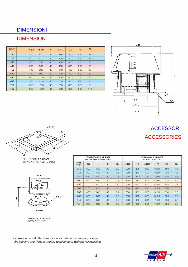
DIMENSIONI
DIMENSION
FAT A x A B x B C D x D ∅∅ E HKg
250 400 470 40 350 200 460 14
315 400 470 40 350 250 460 18
350 560 595 40 460 300 560 25
400 560 595 40 460 350 560 30
450 710 800 40 610 400 620 40
500 710 800 40 610 450 620 48
560 900 1000 40 800 500 790 57
630 900 1000 45 800 550 830 76
710 900 1000 45 800 600 870 96
750 900 1000 45 800 600 880 110
Ci riserviamo il diritto di modificare i dati tecnici senza preavvisoWe reserve the right to modify tecnical data without forewarning
ACCESSORI
ACCESSORIES
CONTROBASE A MURARESUPPORTING FRAME WALL
SERRANDA A GRAVITÀGRAVITY SHUTTER
TIPOTYPE AC L P Kg ∅∅ DS ∅∅ S ∅∅ DSE ∅∅ FS HS Kg
250 390 350 40 0,8 200 235 259 3x8M 150 1,1
315 390 350 40 0,8 250 283 309 3x8M 210 1,8
350 550 460 40 1,6 300 330 359 3x8M 210 2,6
400 550 460 40 1,6 350 381 409 4x8M 230 3,4
450 700 610 40 2 400 431 460 4x8M 250 4,2
500 700 610 40 2 450 485 510 5x8M 300 5,0
560 890 800 40 3,2 500 533 560 5x8M 300 5,8
630 890 800 45 3,2 550 585 620 6x8M 320 6,6
710 890 800 45 3,2 600 636 661 7x8M 320 7,3
750 890 800 45 3,2 600 636 661 7x8M 320 7,3
4
NORME DI INSTALLAZIONE
INSTALLATION PROCEDURE
5
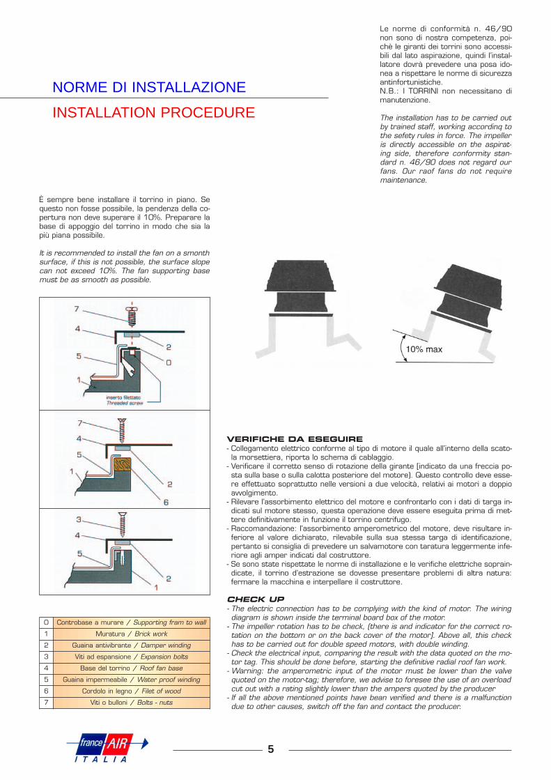
È sempre bene installare il torrino in piano. Sequesto non fosse possibile, la pendenza della co-pertura non deve superare il 10%. Preparare labase di appoggio del torrino in modo che sia lapiù piana possibile.
It is recommended to install the fan on a smonthsurface, if this is not possible, the surface slopecan not exceed 10%. The fan supporting basemust be as smooth as possible.
Le norme di conformità n. 46/90non sono di nostra competenza, poi-chè le giranti dei torrini sono accessi-bili dal lato aspirazione, quindi l’instal-latore dovrà prevedere una posa ido-nea a rispettare le norme di sicurezzaantinfortunistiche.N.B.: I TORRINI non necessitano dimanutenzione.
The installation has to be carried outby trained staff, working accordinq tothe sefety rules in force. The impelleris directly accessible on the aspirat-ing side, therefore conformity stan-dard n. 46/9O does not regard ourfans. Our raof fans do not requiremaintenance.
VERIFICHE DA ESEGUIRE- Collegamento elettrico conforme al tipo di motore il quale all’interno della scato-la morsettiera, riporta lo schema di cablaggio.
- Verificare il corretto senso di rotazione della girante [indicato da una freccia po-sta sulla base o sulla calotta posteriore del motore). Questo controllo deve esse-re effettuato soprattutto nelle versioni a due velocità, relativi ai motori a doppioavvolgimento.
- Rilevare l’assorbimento elettrico del motore e confrontarlo con i dati di targa in-dicati sul motore stesso, questa operazione deve essere eseguita prima di met-tere definitivamente in funzione il torrino centrifugo.
- Raccomandazione: I’assorbimento amperometrico del motore, deve risultare in-feriore al valore dichiarato, rilevabile sulla sua stessa targa di identificazione,pertanto si consiglia di prevedere un salvamotore con taratura leggermente infe-riore agli amper indicati dal costruttore.
- Se sono state rispettate le norme di installazione e le verifiche elettriche soprain-dicate, il torrino d’estrazione se dovesse presentare problemi di altra natura:fermare la macchina e interpellare il costruttore.
CHECK UP- The electric connection has to be complying with the kind of motor. The wiringdiagram is shown inside the terminal board box of the motor.
- The impeller rotation has to be check, (there is and indicator for the correct ro-tation on the bottom or on the back cover of the motor]. Above all, this checkhas to be carried out for double speed motors, with double winding.
- Check the electrical input, comparing the result with the data quoted on the mo-tor tag. This should be done before, starting the definitive radial roof fan work.
- Warning: the amperometric input of the motor must be lower than the valvequoted on the motor-tag; therefore, we advise to foresee the use of an overloadcut out with a rating slightly lower than the ampers quoted by the producer
- If all the above mentioned points have bean verified and there is a malfunctiondue to other causes, switch off the fan and contact the producer.
0 Controbase a murare / Supporting fram to wall
1 Muratura / Brick work
2 Guaina antivibrante / Damper winding
3 Viti ad espansione / Expansion bolts
4 Base del torrino / Roof fan base
5 Guaina impermeabile / Water proof winding
6 Cordolo in legno / Filet of wood
7 Viti o bulloni / Bolts - nuts
6
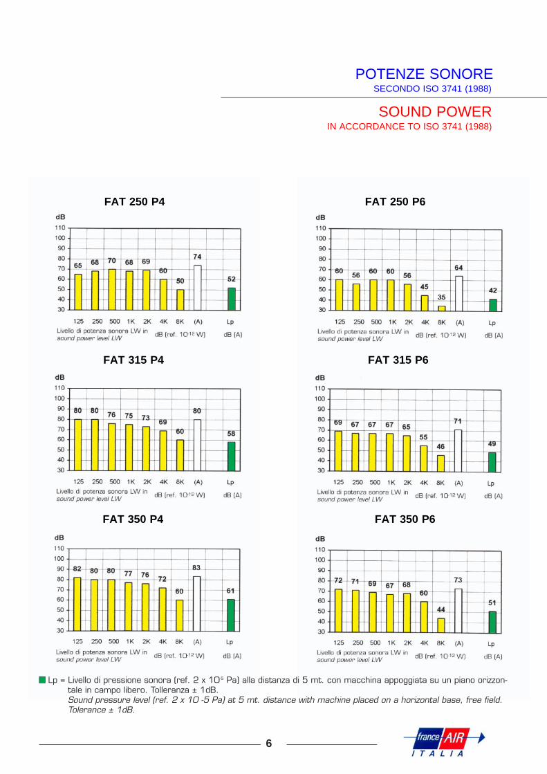
POTENZE SONORESECONDO ISO 3741 (1988)
SOUND POWERIN ACCORDANCE TO ISO 3741 (1988)
FAT 250 P4
FAT 315 P4
FAT 350 P4
FAT 250 P6
FAT 315 P6
FAT 350 P6
Lp = Livello di pressione sonora (ref. 2 x 10⁻⁵ Pa) alla distanza di 5 mt. con macchina appoggiata su un piano orizzon-tale in campo libero. Tolleranza ± 1dB.Sound pressure level (ref. 2 x 10 -5 Pa) at 5 mt. distance with machine placed on a horizontal base, free field.Tolerance ± 1dB.
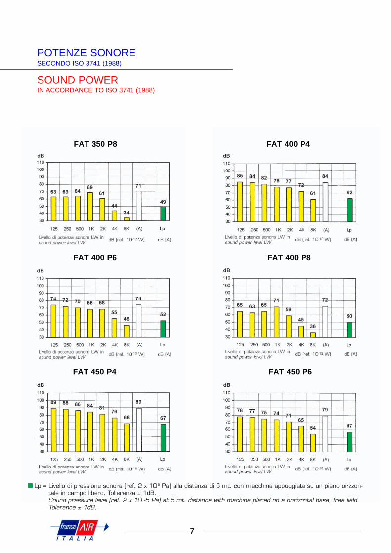
POTENZE SONORESECONDO ISO 3741 (1988)
SOUND POWERIN ACCORDANCE TO ISO 3741 (1988)
7
FAT 350 P8
FAT 400 P6
FAT 450 P4
FAT 400 P4
FAT 400 P8
FAT 450 P6
Lp = Livello di pressione sonora (ref. 2 x 10⁻⁵ Pa) alla distanza di 5 mt. con macchina appoggiata su un piano orizzon-tale in campo libero. Tolleranza ± 1dB.Sound pressure level (ref. 2 x 10 -5 Pa) at 5 mt. distance with machine placed on a horizontal base, free field.Tolerance ± 1dB.

8
POTENZE SONORESECONDO ISO 3741 (1988)
SOUND POWERIN ACCORDANCE TO ISO 3741 (1988)
FAT 450 P8
FAT 500 P6
FAT 560 P6
FAT 500 P4
FAT 500 P8
FAT 560 P8
Lp = Livello di pressione sonora (ref. 2 x 10⁻⁵ Pa) alla distanza di 5 mt. con macchina appoggiata su un piano orizzon-tale in campo libero. Tolleranza ± 1dB.Sound pressure level (ref. 2 x 10 -5 Pa) at 5 mt. distance with machine placed on a horizontal base, free field.Tolerance ± 1dB.

POTENZE SONORESECONDO ISO 3741 (1988)
SOUND POWERIN ACCORDANCE TO ISO 3741 (1988)
9
FAT 630 P6
FAT 710 P6
FAT 750 P6
FAT 630 P8
FAT 710 P8
FAT 750 P8
Lp = Livello di pressione sonora (ref. 2 x 10⁻⁵ Pa) alla distanza di 5 mt. con macchina appoggiata su un piano orizzon-tale in campo libero. Tolleranza ± 1dB.Sound pressure level (ref. 2 x 10 -5 Pa) at 5 mt. distance with machine placed on a horizontal base, free field.Tolerance ± 1dB.

10
COLLEGAMENTI ELETTRICIMONOFASE
ELETTRICAL CONNECTIONSSINGLE-PHASE
Schema di collegamento alla morsetteria / Wiring diagram to the terminal board
Motori ad 1 velocità
1 speed engine
MEC 71÷90monofase standard
standard single-phaseV.230/50 Hz V.230/50 Hz
rotazione antiorariacounter clockwise rotation
rotazione orariaclockwise rotation
ATTENZIONEVERIFICARE IL SENSO
DI ROTAZIONE
WARNINGVERIFY THE ROTATION
Schema di collegamento alla morsetteria / Wiring diagram to the terminal board
Motori ad 1 velocità
1 speed engine
MEC 50÷63monofase regolabile
adjustable single-phase
V.230/50 Hz V.230/50 Hz
rotazione antiorariacounter clockwise rotation
rotazione orariaclockwise rotation
ATTENZIONEVERIFICARE IL SENSO
DI ROTAZIONE
WARNINGVERIFY THE ROTATION
Schema di collegamento alla morsetteria / Wiring diagram to the terminal board
Motori ad 1 velocità
1 speed engine
MEC 71÷90monofase regolabile
adjustable single-phase
V.230/50 Hz V.230/50 Hz
rotazione antiorariacounter clockwise rotation
rotazione orariaclockwise rotation
ATTENZIONEVERIFICARE IL SENSO
DI ROTAZIONE
WARNINGVERIFY THE ROTATION

COLLEGAMENTI ELETTRICITRIFASE
ELETTRICAL CONNECTIONSTHREE-PHASE
11
Schema di collegamento alla morsetteria / Wiring diagram to the terminal board
Schema di collegamento alla morsetteria / Wiring diagram to the terminal board
Motori a 2 velocitàcon 2 avvolgimenti separati
2 speed enginewith windings separated
4/6 poli6/8 poli
V400/50 Hz
ATTENZIONEVERIFICARE IL SENSO
DI ROTAZIONE
WARNINGVERIFY THE ROTATION
collegamento a
connectioncollegamento a
connection
ATTENZIONEVERIFICARE IL SENSO DI
ROTAZIONE PER ENTRAMBE LE DUE VELOCITÀ
WARNINGVERIFY THE ROTATION OF
BOTH SPEEDS
alta velocità / high speed
bassa velocità / low speed
Motori ad 1 velocità
1 speed engine

DATI ELETTRICI E DI REGOLAZIONE
REGULATION AND ELECTRICALDATA SHEET
VelocitàSpeed
G/Min. RPM
Potenzamotore
Motor power
TensioneVoltage
Volt/Fasi/Hz
Targa MotoreMotor PlateI. max Amp.
RegolatoreTrifaseSpeed
controller
Targa MotoreMotor PlateI. max Amp.
RegolatoreMonofase
Speedcontroller
1
N
12
Kw Volt/Ph./Hz Three-phase Single-phaseV. 230 V. 400 V.230/1F/50
250 P4 1400 0,12 230/400/3/50 0,81 0,47 VT4000 1,16 RV30005 P6 900 0,09 230/400/3/50 0,43 0,25 VT4000 0,70 RV300
05 P4/6 1400/900 0,12/0,09 400/690/3/50 0,65 0,35 -20 P4 1400 0,18 230/400/3/50 1,05 0,60 VT4000 1,70 RV30020 P6 900 0,09 230/400/3/50 0,43 0,25 VT4000 0,70 RV300
20 P4/6 1400/900 0,25/0,07 400/400/3/50 0,82/0,4 -30 P4 1400 0,25 230/400/3/50 1,40 0,82 VT4000 2,2 RV30030 P6 900 0,18 230/400/3/50 1,23 0,71 VT4000 2,0 RV30030 P8 700 0,12 230/400/3/50 1,21 0,70 -
30 P4/6 1400/900 0,25/0,07 400/400/3/50 0,82/0,4 -40 P4 1400 0,37 230/400/3/50 1,90 1,10 VT4000 3,2 RV60040 P6 900 0,18 230/400/3/50 1,23 0,71 VT4000 2,0 RV60040 P8 700 0,12 230/400/3/50 1,21 0,70 -
40 P4/6 1400/900 0,37/0,12 400/400/3/50 1,1/0,7 -50 P4 1400 0,75 230/400/3/50 3,40 1,80 VT4000 5,30 RV90050 P6 900 0,37 230/400/3/50 2,00 1,15 VT4000 3,20 RV60050 P8 700 0,18 230/400/3/50 1,50 0,86 -
50 P4/6 1400/900 0,75/0,25 400/400/3/50 2,0/1,30 -50 P6/8 900/700 0,37/0,15 400/400/3/50 1,5/0,7 -
60 P4 1400 1,1 230/400/3/50 4,80 2,80 VT400060 P6 900 0,37 230/400/3/50 2,00 1,15 VT700060 P8 700 0,18 230/400/3/50 1,50 0,86 -
60 P4/6 1400/900 1,1/0,37 400/400/3/50 2,8/1,15 -60 P6/8 900/700 0,37/0,15 400/400/3/50 1,15/0,7 -
70 P6 900 0,75 230/400/3/50 3,80 2,20 VT400070 P8 700 0,37 230/400/3/50 2,40 1,40 -
70 P6/8 900/700 0,66/0,33 400/400/3/50 1,8/1,25 -80 P6 900 1,1 230/400/3/50 5,40 3,10 VT400080 P8 700 0,55 230/400/3/50 3,60 2,0 -
80 P6/8 900/700 1,25/0,6 400/400/3/50 3,6/2,5 -90 P6 900 2,2 230/400/3/50 9,40 5,40 VT700090 P8 700 1,1 230/400/3/50 5,50 3,20 -
90 P6/8 900/700 1,84/0,81 400/400/3/50 4,0/3,1 -100 P6 900 3 230/400/3/50 12,0 6,9 VT14000100 P8 700 2,2 230/400/3/50 9,70 5,60 -00 P6/8 900/700 3/1,5 400/400/3/50 6,9/4,2 -
.B.: Tutti i regolatori trifase “RD” sono ad autotrasformatore da alimentare solo a V. 400/3F/50 Hz.The three-phase regulators “RD” are autotransformer to power only with V. 400/3F/50 Hz.I regolatori monofase “RMM-RMD” lavorano con regolazione a parzializzzazione di fase V. 230/1F/50 Hz.Single phase regulators “RMM-RMD” work with system of rheostatic control V. 230/1F/50 Hz.