Embed Size (px)
Citation preview
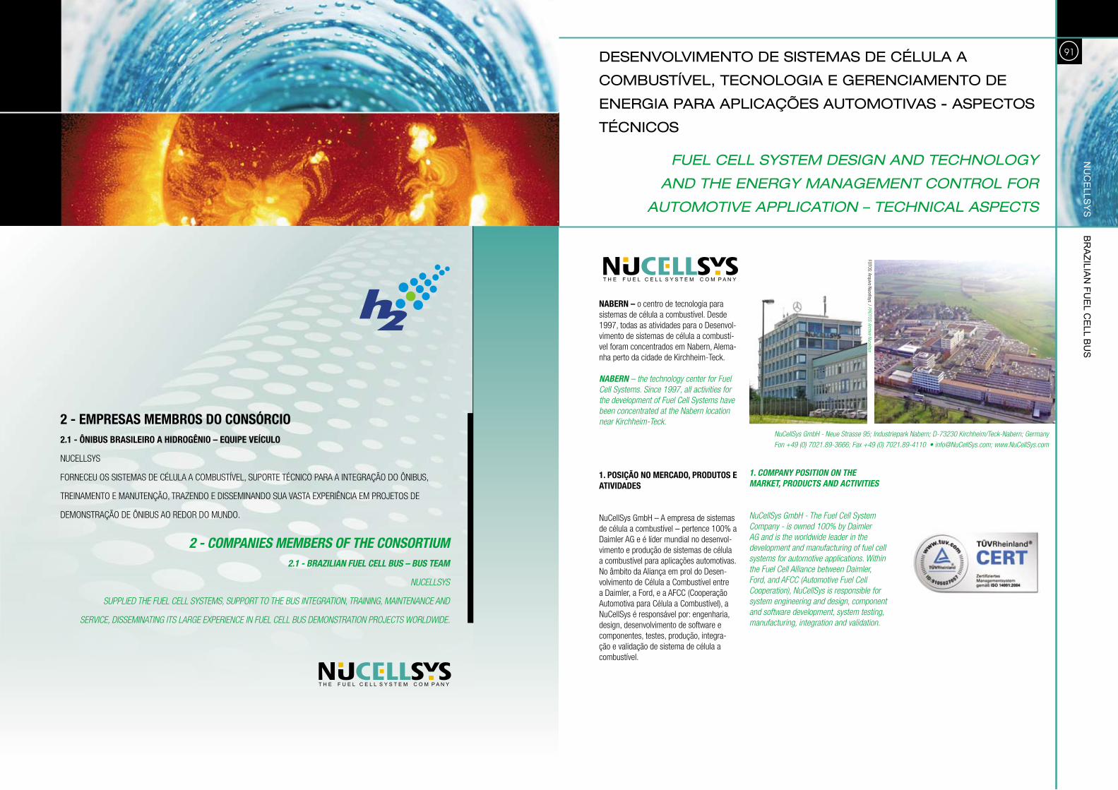
2 - EMPRESAS MEMBROS DO CONSÓRCIO2.1 - ÔNIBUS BRASILEIRO A HIDROGÊNIO – EQUIPE VEÍCULO
nUcellsys
FoRneceU os sisTeMas de célUla a coMbUsTÍvel, sUpoRTe Técnico paRa a inTegRação do ÔnibUs,
TReinaMenTo e ManUTenção, TRaZendo e disseMinando sUa vasTa eXpeRiência eM pRojeTos de
deMonsTRação de ÔnibUs ao RedoR do MUndo.
2 - COMPANIES MEMBERS OF THE CONSORTIUM 2.1 - BRAZILIAN FUEL CELL BUS – BUS TEAM
NUCELLSyS
SUPPLIEd THE FUEL CELL SySTEMS, SUPPORT TO THE BUS INTEGRATION, TRAINING, MAINTENANCE ANd
SERvICE, dISSEMINATING ITS LARGE EXPERIENCE IN FUEL CELL BUS dEMONSTRATION PROjECTS WORLdWIdE.
180DESENVOLVIMENTO DE SISTEMAS DE CÉLULA A
COMBUSTÍVEL, TECNOLOGIA E GERENCIAMENTO DE
ENERGIA PARA APLICAÇÕES AUTOMOTIVAS - ASPECTOS
TÉCNICOS
NABERN – o centro de tecnologia para sistemas de célula a combustível. desde 1997, todas as atividades para o desenvol-vimento de sistemas de célula a combustí-vel foram concentrados em nabern, alema-nha perto da cidade de Kirchheim-Teck.
NABERN – the technology center for Fuel Cell Systems. Since 1997, all activities for the development of Fuel Cell Systems have been concentrated at the Nabern location near Kirchheim-Teck.
1. POSIÇÃO NO MERCADO, PRODUTOS E ATIVIDADES
nucellsys gmbH – a empresa de sistemas de célula a combustível – pertence 100% a daimler ag e é líder mundial no desenvol-vimento e produção de sistemas de célula a combustível para aplicações automotivas. no âmbito da aliança em prol do desen-volvimento de célula a combustível entre a daimler, a Ford, e a aFcc (cooperação automotiva para célula a combustível), a nucellsys é responsável por: engenharia, design, desenvolvimento de software e componentes, testes, produção, integra-ção e validação de sistema de célula a combustível.
NuCellSys GmbH - Neue Strasse 95; Industriepark Nabern; d-73230 Kirchheim/Teck-Nabern; Germany
Fon +49 (0) 7021.89-3666; Fax +49 (0) 7021.89-4110 • [email protected]; www.NuCellSys.com
1. COMPANY POSITION ON THE MARKET, PRODUCTS AND ACTIVITIES
NuCellSys GmbH - The Fuel Cell System Company - is owned 100% by daimler AG and is the worldwide leader in the development and manufacturing of fuel cell systems for automotive applications. Within the Fuel Cell Alliance between daimler, Ford, and AFCC (Automotive Fuel Cell Cooperation), NuCellSys is responsible for system engineering and design, component and software development, system testing, manufacturing, integration and validation.
nu
Ce
llsY
s br
azilia
n Fu
el C
ell b
us
91
FoTos: arquivo nucellsys / PHOTOS: Archive Nucellsys
FUEL CELL SYSTEM DESIGN AND TECHNOLOGY
AND THE ENERGY MANAGEMENT CONTROL FOR
AUTOMOTIVE APPLICATION – TECHNICAL ASPECTS
92
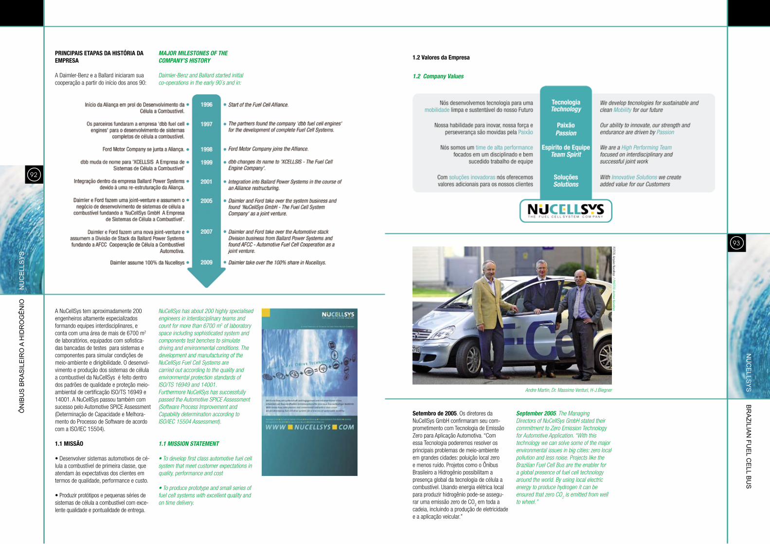
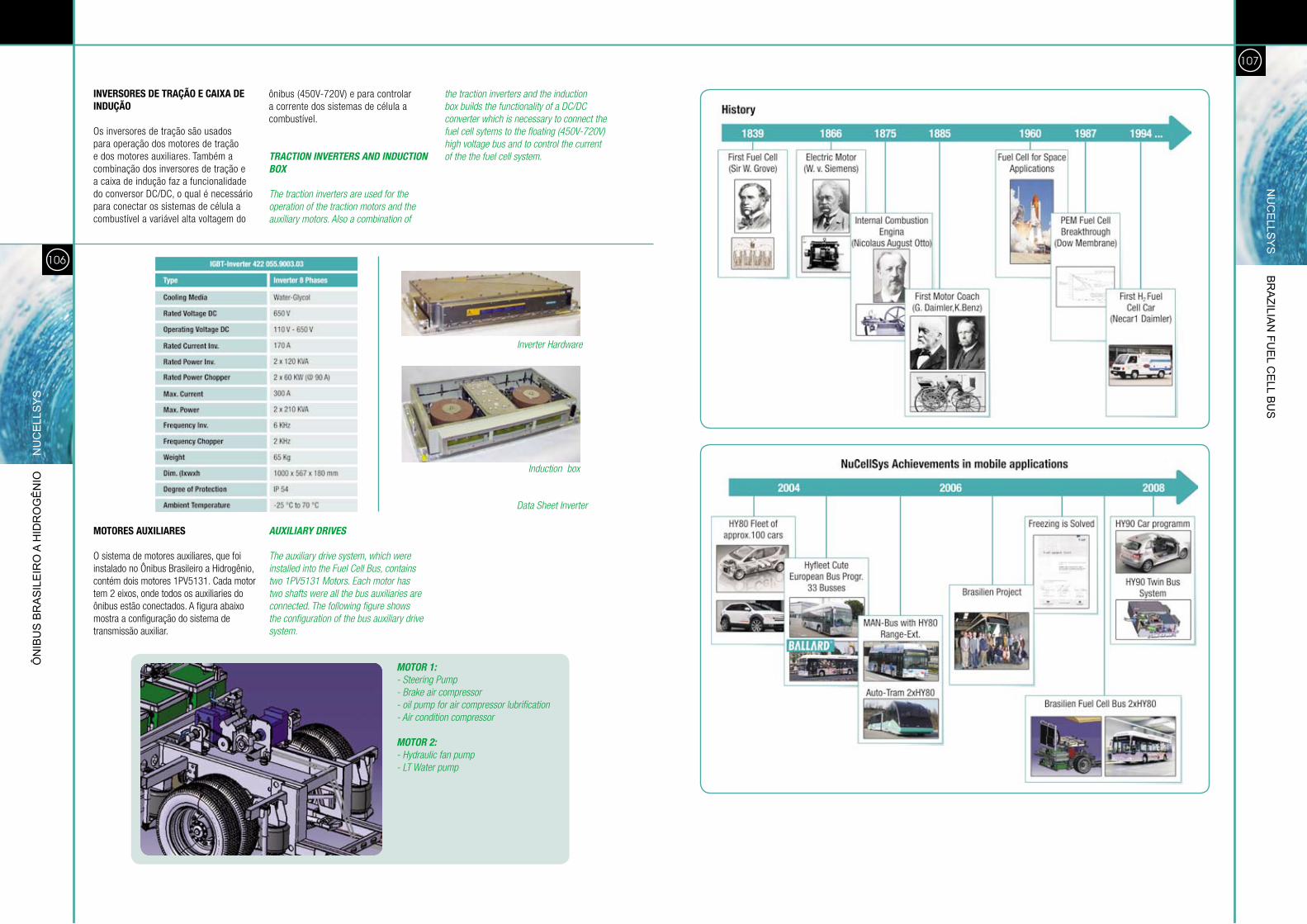
PRINCIPAIS ETAPAS DA HISTÓRIA DA EMPRESA
a daimler-benz e a ballard iniciaram sua cooperação a partir do início dos anos 90:
MAJOR MILESTONES OF THE COMPANY’S HISTORY
daimler-Benz and Ballard started initial co-operations in the early 90´s and in:
a nucellsys tem aproximadamente 200 engenheiros altamente especializados formando equipes interdisciplinares, e conta com uma área de mais de 6700 m2 de laboratórios, equipados com sofistica-das bancadas de testes para sistemas e componentes para simular condições de meio-ambiente e dirigibilidade. o desenvol-vimento e produção dos sistemas de célula a combustível da nucellsys é feito dentro dos padrões de qualidade e proteção meio-ambiental de certificação iso/Ts 16949 e 14001. a nucellsys passou também com sucesso pelo automotive spice assessment (determinação de capacidade e Melhora-mento do processo de software de acordo com a iso/iec 15504).
1.1 MISSÃO
• desenvolver sistemas automotivos de cé-lula a combustível de primeira classe, que atendam às expectativas dos clientes em termos de qualidade, performance e custo.
• produzir protótipos e pequenas séries de sistemas de célula a combustível com exce-lente qualidade e pontualidade de entrega.
NuCellSys has about 200 highly specialised engineers in interdisciplinary teams and count for more than 6700 m2 of laboratory space including sophisticated system and components test benches to simulate driving and environmental conditions. The development and manufacturing of the NuCellSys Fuel Cell Systems arecarried out according to the quality and environmental protection standards of ISO/TS 16949 and 14001.Furthermore NuCellSys has successfully passed the Automotive SPICE Assessment (Software Process Improvement and Capability determination according to ISO/IEC 15504 Assessment).
1.1 MISSION STATEMENT
• To develop first class automotive fuel cell system that meet customer expectations in quality, performance and cost
• To produce prototype and small series of fuel cell systems with excellent quality and on time delivery.
Ôn
ibu
s b
ra
sil
eir
o a
Hid
ro
gê
nio
n
uC
ell
sY
s
93
1.2 Company Values
Setembro de 2005. os diretores da nucellsys gmbH confirmaram seu com-prometimento com Tecnologia de emissão Zero para aplicação automotiva. “com essa Tecnologia poderemos resolver os principais problemas de meio-ambiente em grandes cidades: poluição local zero e menos ruído. projetos como o Ônibus brasileiro a Hidrogênio possibilitam a presença global da tecnologia de célula a combustível. Usando energia elétrica local para produzir hidrogênio pode-se assegu-rar uma emissão zero de co
2 em toda a
cadeia, incluindo a produção de eletricidade e a aplicação veicular.”
September 2005. The Managing directors of NuCellSys GmbH stated their commitment to Zero Emission Technology for Automotive Application. “With this technology we can solve some of the major environmental issues in big cities: zero local pollution and less noise. Projects like the Brazilian Fuel Cell Bus are the enabler for a global presence of fuel cell technology around the world. By using local electric energy to produce hydrogen it can be ensured that zero CO
2 is emitted from well
to wheel.”
Andre Martin, dr. Massimo venturi, H-j.Biegner
nu
Ce
llsY
s br
azilia
n Fu
el C
ell b
us
1.2 Valores da Empresa
FoTos: arquivo nucellsys / PHOTOS: Archive Nucellsys
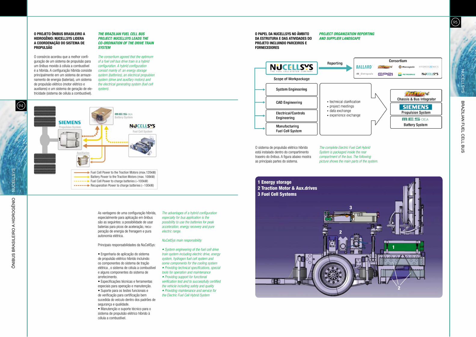
o sistema de propulsão elétrico híbrido está instalado dentro do compartimento traseiro do ônibus. a figura abaixo mostra as principais partes do sistema.
The complete Electric Fuel Cell Hybrid System is packaged inside the rear compartment of the bus. The following picture shows the main parts of the system.
95
94
O PROJETO ÔNIBUS BRASILEIRO A HIDROGÊNIO: NUCELLSyS LIDERA A COORDENAÇÃO DO SISTEMA DE PROPULSÃO
o consórcio acordou que a melhor confi-guração de um sistema de propulsão para um ônibus movido à célula a combustível é a híbrida. a configuração híbrida consiste principalmente em um sistema de armaze-namento de energia (baterias), um sistema de propulsão elétrico (motor elétrico e auxiliares) e um sistema de geração de ele-tricidade (sistema de célula a combustível).
THE BRAZILIAN FUEL CELL BUS PROJECT: NUCELLSYS LEADS THE CO-ORDINATION OF THE DRIVE TRAIN SYSTEM
The consortium agreed that the optimum of a fuel cell bus drive train is a hybrid configuration. A hybrid configuration consist mainly of: an energy storage system (batteries), an electrical propulsion system (drive and auxillary motors) and the electrical generating system (fuel cell system).
as vantagens de uma configuração híbrida, especialmente para aplicação em ônibus são as seguintes: a possibilidade de usar baterias para picos de aceleração, recu-peração de energia de frenagem e pura autonomia elétrica.
principais responsabilidades da nucellsys:
• engenharia de aplicação do sistema de propulsão elétrico híbrido incluindo: os componentes do sistema de tração elétrica , o sistema de célula a combustível e alguns componentes do sistema de arrefecimento. • especificações técnicas e ferramentas especiais para operação e manutenção.• suporte para os testes funcionais e de verificação para certificação bem sucedida do veículo dentro dos padrões de segurança e qualidade.• Manutenção e suporte técnico para o sistema de propulsão elétrico híbrido à célula a combustível.
The advantages of a hybrid configuration especially for bus application is the possibility to use the batteries for peak acceleration, energy recovery and pure electric range.
NuCellSys main responsibility:
• System engineering of the fuel cell drive train system including electric drive, energy system, hydrogen fuel cell system and some components for the cooling system• Providing technical specifications, special tools for operation and maintenance• Providing support for functional verification test and to successfully certified the vehicle including safety and quality• Providing maintenance and service for the Electric Fuel Cell Hybrid System
O PAPEL DA NUCELLSyS NO ÂMBITO DA ESTRUTURA E DAS ATIVIDADES DO PROJETO INCLUINDO PARCEIROS E FORNECEDORES
PROJECT ORGANIZATION REPORTING AND SUPPLIER LANDSCAPE
Ôn
ibu
s b
ra
sil
eir
o a
Hid
ro
gê
nio
n
uC
ell
sY
sn
uC
ells
Ys b
ra
zilian
Fue
l Ce
ll bu
s
1 Energy storage2 Traction Motor & Aux.drives3 Fuel Cell Systems
1
2
2
3
97
96
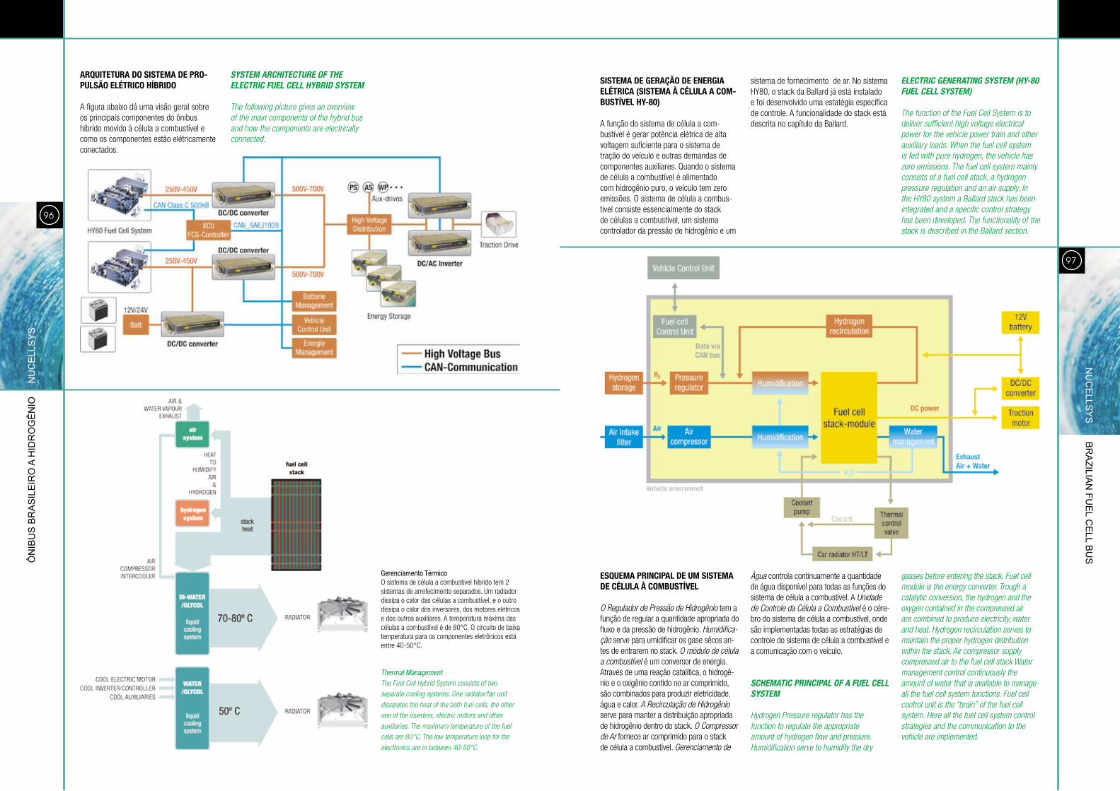
ARQUITETURA DO SISTEMA DE PRO-PULSÃO ELÉTRICO HÍBRIDO
a figura abaixo dá uma visão geral sobre os principais componentes do ônibus híbrido movido à célula a combustível e como os componentes estão elétricamente conectados.
SYSTEM ARCHITECTURE OF THE ELECTRIC FUEL CELL HYBRID SYSTEM
The following picture gives an overview of the main components of the hybrid bus and how the components are electrically connected.
SISTEMA DE GERAÇÃO DE ENERGIA ELÉTRICA (SISTEMA À CÉLULA A COM-BUSTÍVEL Hy-80)
a função do sistema de célula a com-bustível é gerar potência elétrica de alta voltagem suficiente para o sistema de tração do veículo e outras demandas de componentes auxiliares. Quando o sistema de célula a combustível é alimentado com hidrogênio puro, o veículo tem zero emissões. o sistema de célula a combus-tível consiste essencialmente do stack de células a combustível, um sistema controlador da pressão de hidrogênio e um
sistema de fornecimento de ar. no sistema Hy80, o stack da ballard já está instalado e foi desenvolvido uma estatégia específica de controle. a funcionalidade do stack está descrita no capítulo da ballard.
ELECTRIC GENERATING SYSTEM (HY-80 FUEL CELL SYSTEM)
The function of the Fuel Cell System is to deliver sufficient high voltage electrical power for the vehicle power train and other auxiliary loads. When the fuel cell system is fed with pure hydrogen, the vehicle has zero emissions. The fuel cell system mainly consists of a fuel cell stack, a hydrogen pressure regulation and an air supply. In the Hy80 system a Ballard stack has been integrated and a specific control strategy has been developed. The functionality of the stack is described in the Ballard section.
ESQUEMA PRINCIPAL DE UM SISTEMA DE CÉLULA À COMBUSTÍVEL
O Regulador de Pressão de Hidrogênio tem a função de regular a quantidade apropriada do fluxo e da pressão de hidrogênio. Humidifica-ção serve para umidificar os gase sêcos an-tes de entrarem no stack. O módulo de célula a combustível é um conversor de energia. através de uma reação catalítica, o hidrogê-nio e o oxigênio contido no ar comprimido, são combinados para produzir eletricidade, água e calor. A Recirculação de Hidrogênio serve para manter a distribuição apropriada de hidrogênio dentro do stack. O Compressor de Ar fornece ar comprimido para o stack de célula a combustível. Gerenciamento de
Água controla continuamente a quantidade de água disponível para todas as funções do sistema de célula a combustível. a Unidade de Controle da Célula a Combustível é o cére-bro do sistema de célula a combustível, onde são implementadas todas as estratégias de controle do sistema de célula a combustível e a comunicação com o veículo.
SCHEMATIC PRINCIPAL OF A FUEL CELL SYSTEM
Hydrogen Pressure regulator has the function to regulate the appropriate amount of hydrogen flow and pressure. Humidification serve to humidify the dry
gasses before entering the stack. Fuel cell module is the energy converter. Trough a catalytic conversion, the hydrogen and the oxygen contained in the compressed air are combined to produce electricity, water and heat. Hydrogen recirculation serves to maintain the proper hydrogen distribution within the stack. Air compressor supply compressed air to the fuel cell stack Water management control continuously the amount of water that is available to manage all the fuel cell system functions. Fuel cell control unit is the “brain” of the fuel cell system. Here all the fuel cell system control strategies and the communication to the vehicle are implemented.
Ôn
ibu
s b
ra
sil
eir
o a
Hid
ro
gê
nio
n
uC
ell
sY
sn
uC
ells
Ys b
ra
zilian
Fue
l Ce
ll bu
s Gerenciamento Térmico
o sistema de célula a combustível híbrido tem 2 sistemas de arrefecimento separados. Um radiador dissipa o calor das células a combustível, e o outro dissipa o calor dos inversores, dos motores elétricos e dos outros auxiliares. a temperatura máxima das células a combustível é de 80°c. o circuito de baixa temperatura para os componentes eletrônicos está entre 40-50°c.
Thermal ManagementThe Fuel Cell Hybrid System consists of two
separate cooling systems. One radiator/fan unit
dissipates the heat of the both fuel cells, the other
one of the inverters, electric motors and other
auxiliaries. The maximum temperature of the fuel
cells are 80°C. The low temperature loop for the
electronics are in between 40-50°C.
99
98
a nucellsys desenvolveu o sistema de célula a combustível submetendo-o a vários testes automotivos, como por exemplo: crash, vibração, teste de compatibilidade eletro-magnética, jato de água e imersão, câmara climática e de durabilidade.
A NuCellSys desenvolveu o sistema de célula a combustível submetendo-o a vários testes automotivos, como por exemplo: crash, vibração, teste de compatibilidade eletro-magnética, jato de água e imersão, câmara climática e de durabilidade.
o sistema de célula a combustível da nucellsys foi desenhado para aplicação em veículos de passeio. Usando 2 (ou mais) sistemas Hy80 é possivel atender a neces-sidade de maior potência das aplicações em veículos pesados, como por exemplo em ônibus.
os dois sistemas de célula a combustível são montados no ônibus em uma estrutura especial (que não está mostrada nesta figura). ambos sistemas de célula a com-bustível podem ser controlados separada-mente pela Unidade de controle veicular. as conecções hidráulicas e elétricas são desenhadas para atender as especificações e permitir uma operação independente de cada sistema de célula a combustível. o sistema de controle de cada sistema de célula a combustível consiste em um controlador principal (FcU) e controladores subordinados. o controlador principal do sistema de célula a combustível é subor-dinado a Unidade de controle de Relacio-namento (XcU). essa XcU tem uma função de saída entre as Unidades de controle da célula a combustível e a Unidade de controle veicular. a operação interativa via can bus garante um funcionamento seguro e eficiente entre todos os controladores.
1
2
4/5
6
3
1
2
4/5
6
3
NuCellSys Fuel Cell Systems have been designed for a passenger car application. By using 2 Hy80 Systems (or more) it is possible to meet the power requirement for heavy duty applications such as busses.
SISTEMAS À CÉLULA A COMBUSTÍVEL
os dois sistemas de célula a combustível Hy80 mostrados na figura abaixo consistem dos seguintes sub-módulos:
1. stack de célula a combustível2. sistema de célula a combustível3. Unidade de distribuição de potência4. Unidade de controle5. Unidade de Monitoramento e interface com o stack6. bomba de arrefecimento de alta voltagem
FUEL CELL SYSTEMS
The two Hy80 Fuel Cell Systems which are shown in the following picture, are consisting of the following sub-modules:
1. Fuel Cell Stack2. Fuel Cell System3. Power distribution Unit4. Fuel Cell Control Unit5. Stack Interface Monitoring Unit6. Hv-Cooling Pump
The two Fuel Cell Systems are assembled into the bus on a special frame (not shown in this picture). Both Fuel Cell Systems can be controlled separately from the vehicle Control Unit. The hydraulic and electric connections are designed to fulfill the specification and to reach an independent operation of each Fuel Cell System. The Control System of each Fuel Cell System consists of a main controller (FCU) and subordinated controllers. The main controller of the Fuel Cell System is subordinated to the exchange Control Unit (XCU). This XCU has a gateway function between the Fuel Cell Control Units and the vehicle Control Unit. The interactive operation via CAN bus guarantees safe and efficient functions between all controllers.
Ôn
ibu
s b
ra
sil
eir
o a
Hid
ro
gê
nio
n
uC
ell
sY
sn
uC
ells
Ys b
ra
zilian
Fue
l Ce
ll bu
s
CrashCrash
Jato de água durante operação Water spray operation
imersão na água durante a operaçãoWater immersion during operation
inclinação em câmara ambiental Inclination in enviromental chamber
Vibração em operação Vibration test in operation
Compatibilidade eletro-magnética Electromagnetic compatibility test
Teste do sistema de célula a combustível na câmara climática com inclinação.
Fuel Cell System Test in Climate Chamber with incline.
FoTos: arquivo nucellsys / PHOTOS: Archive Nucellsys
101
100
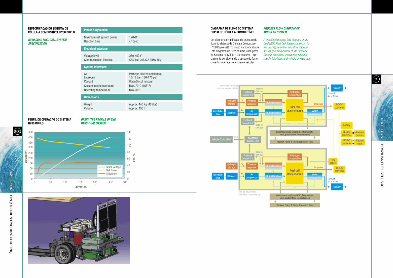
ESPECIFICAÇÃO DO SISTEMA DE CÉLULA A COMBUSTÍVEL Hy80 DUPLO
HY80 DUAL FUEL CELL SYSTEM SPECIFICATION
PERFIL DE OPERAÇÃO DO SISTEMA Hy80 DUPLO
OPERATING PROFILE OF THE HY80-DUAL SYSTEM
DIAGRAMA DE FLUXO DO SISTEMA DUPLO DE CÉLULA A COMBUSTÍVEL
Um diagrama simplificado do processo de fluxo do sistema de célula a combustível Hy80 duplo está mostrado na figura abaixo. este diagrama de fluxo dá uma visão geral do sistema de célula a combustível, espe-cialmente considerando o escopo de forne-cimento, interfaces e ambiente veicular.
PROCESS FLOW DIAGRAM OF MODULAR SYSTEM
A simplified process flow diagram of the dual Hy80 Fuel Cell Systems is shown in the next figure below. This flow diagram should give an overview of the Fuel Cell System, especially considering scope of supply, interfaces and vehicle environment.
Ôn
ibu
s b
ra
sil
eir
o a
Hid
ro
gê
nio
n
uC
ell
sY
sn
uC
ells
Ys b
ra
zilian
Fue
l Ce
ll bu
s
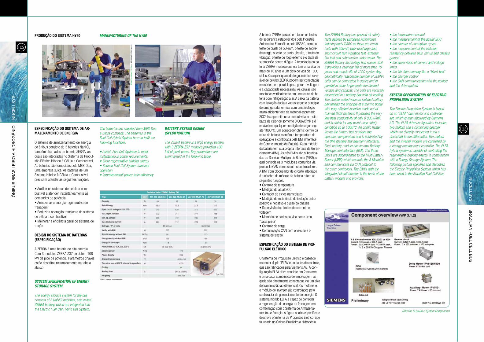
a bateria ZebRa passou em todos os testes de segurança estabelecidos pela indústria automotiva européia e pelo Usabc, como o teste de crash de 50km/h, o teste de sobre-descarga, o teste de curto-circuito, o teste de vibração, o teste de fogo externo e o teste de submersão dentro d’água. a tecnologia da ba-teria ZebRa mostrou que ela tem uma vida de mais de 10 anos e um ciclo de vida de 1000 ciclos. Qualquer quantidade geométrica razo-ável de células ZebRa podem ser conectadas em série e em paralelo para gerar a voltagem e a capacidade necessárias. as células são montadas verticalmente em uma caixa da ba-teria com refrigeração a ar. a caixa da bateria com isolação dupla a vacuo segue o princípio de uma garrafa térmica com uma isolação muito eficiente feita de material espumado sio2. isso permite uma condutividade muito baixa de calor de somente 0.006W/mK e é estável em qualquer condição de segurança até 1000°c. Um aquecedor ohmic dentro da caixa da bateria mantém a temperatura de operação e é controlada pela bMi (interface de gerenciamento da bateria). cada módulo da bateria tem sua própria interface de geren-ciamento (bMi). as três bMi’s são subordina-das ao servidor Múltiplo de bateria (Mbs), o qual controla os 3 módulos e comunica via protocolo can com os outros controladores. a bMi com bloqueador de circuito integrado é o cérebro do módulo da bateria e tem as seguintes funções:• controle de temperatura• Medição do atual soc• contador de ciclos nameplates• Medição de resistência de isolação entre positivo e negativo e o piso do chassis• supervisão dos limites de corrente e voltagem• Memória de dados da vida como uma “caixa prêta”• controle de carga• comunicação can com o veículo e o sistema de tração
ESPECIFICAÇÃO DO SISTEMA DE PRO-PULSÃO ELÉTRICO
o sistema de propulsão elétrico é baseado no motor duplo “elFa“e unidades de controle, que são fabricados pela siemens ag. a con-figuração elFa drive consiste em 2 motores e uma caixa combinada de embreagem, as quais são diretamente conectadas via um eixo de transmissão ao diferencial. os motores e o módulo do inversor são controlados pelo controlador de gerenciamento de energia. o sistema híbrido elFa é capaz de controlar a regeneração de energia de frenagem em combinação com o sistema de armazena-mento de energia. a figura abaixo especifica e descreve o sistema de propulsão elétrico, que foi usado no Ônibus brasileiro a Hidrogênio.
The ZEBRA Battery has passed all safety tests defined by European Automotive Industry and USABC as there are crash tests with 50km/h over-discharge test, short circuit test, vibration test, external fire test and submersion under water. The ZEBRA Battery technology has shown, that it provides a calendar life of more than 10 years and a cycle life of 1000 cycles. Any geometrically reasonable number of ZEBRA cells can be connected in series and in parallel in order to generate the desired voltage and capacity. The cells are vertically assembled in a battery box with air cooling. The double walled vacuum isolated battery box follows the principle of a thermo bottle with very efficient isolation made out of foamed SiO2 material. It provides the very low heat conductivity of only 0.006W/mK and is stable for any worst case safety condition up to 1000°C. An ohmic heater inside the battery box provides the operation temperature and is controlled by the BMI (Battery Management Interface). Each battery module has its own Battery Management Interface (BMI). The three BMI’s are subordinated to the Multi Battery Server (MBS) which controls the 3 Modules and communicate via CAN protocol to the other controllers. The BMI’s with the integrated circuit breaker is the brain of the battery module and provides:
• the temperature control• the measurement of the actual SOC• the counter of nameplate cycles• the measurement of the isolation resistance between plus, minus and chassis ground• the supervision of current and voltage limits• the life data memory like a “black box”• the charger control• the CAN communication with the vehicle and the drive system
SYSTEM SPECIFICATION OF ELECTRIC PROPULSION SYSTEM
The Electric Propulsion System is based on an “ELFA“ dual motor and controller set, which is manufactured by Siemens AG. The ELFA drive configuration includes two motors and a combining gearbox which are directly connected to via a driveshaft to the differential. The motors and the inverter module are controlled by a energy management controller. The ELFA hybrid system is capable of controlling the regenerative braking energy in combination with a Energy Storage System. The following picture specifies and describes the Electric Propulsion System which has been used in the Brazilian Fuel Cell Bus.
103
102
PRODUÇÃO DO SISTEMA Hy80 MANUFACTURING OF THE HY80
ESPECIFICAÇÃO DO SISTEMA DE AR-MAZENAMENTO DE ENERGIA
o sistema de armazenamento de energia do ônibus consiste de 3 baterias nanicl, também chamadas de bateria ZebRa, as quais são integradas no sistema de propul-são elétrico Híbrido á célula a combustível. as baterias são fornecidas pela Mes-dea, uma empresa suiça. as baterias de um sistema Híbrido à célula a combustível precisam atender às seguintes funções:
• auxiliar os sistemas de célula a com-bustível a atender instantâneamente as demandas de potência.• armazenar a energia regenerativa de frenagem • Reduzir a operação transiente do sistema de célula a combustível• Melhorar a eficiência geral do sistema de tração
DESIGN DO SISTEMA DE BATERIAS (ESPECIFICAÇÃO)
a ZebRa é uma bateria de alta energia. com 3 módulos ZebRa Z37 se obtém 108 kW de pico de potência. parâmetros chaves estão descritos resumidamente na tabela abaixo.
SYSTEM SPECIFICATION OF ENERGY STORAGE SYSTEM
The energy storage system for the bus consists of 3 NaNiCl batteries, also called ZEBRA battery, which are integrated into the Electric Fuel Cell Hybrid Bus System. Siemens ELFA drive System Components
Ôn
ibu
s b
ra
sil
eir
o a
Hid
ro
gê
nio
n
uC
ell
sY
sn
uC
ells
Ys b
ra
zilian
Fue
l Ce
ll bu
s
The batteries are supplied from MES-dea a Swiss company. The batteries in the Fuel Cell Hybrid System have to fulfil the following functions:
• Assist Fuel Cell Systems to meet instantaneous power requirements.• Store regenerative braking energy• Reduce Fuel Cell System transient operation• Improve overall power train efficiency
BATTERY SYSTEM DESIGN (SPECIFICATION)
The ZEBRA battery is a high energy battery, with 3 ZEBRA Z37 modules providing 108 kW of peak power. Key parameters are summarized in the following table.
FoTos: arquivo nucellsys / PHOTOS: Archive Nucellsys
105104
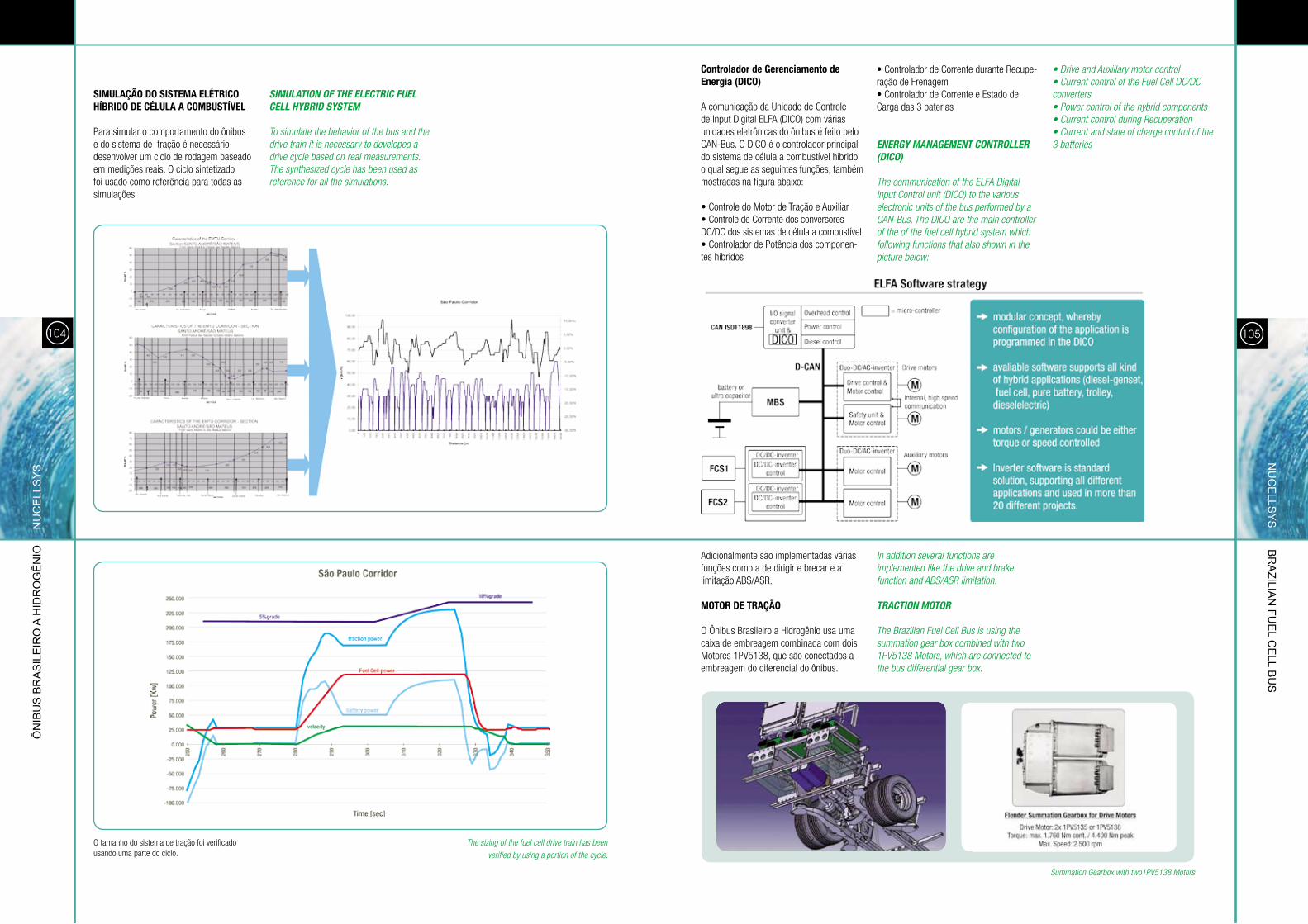
SIMULAÇÃO DO SISTEMA ELÉTRICO HÍBRIDO DE CÉLULA A COMBUSTÍVEL
para simular o comportamento do ônibus e do sistema de tração é necessário desenvolver um ciclo de rodagem baseado em medições reais. o ciclo sintetizado foi usado como referência para todas as simulações.
SIMULATION OF THE ELECTRIC FUEL CELL HYBRID SYSTEM
To simulate the behavior of the bus and the drive train it is necessary to developed a drive cycle based on real measurements. The synthesized cycle has been used as reference for all the simulations.
o tamanho do sistema de tração foi verificado usando uma parte do ciclo.
Controlador de Gerenciamento de Energia (DICO)
a comunicação da Unidade de controle de input digital elFa (dico) com várias unidades eletrônicas do ônibus é feito pelo can-bus. o dico é o controlador principal do sistema de célula a combustível híbrido, o qual segue as seguintes funções, também mostradas na figura abaixo:
• controle do Motor de Tração e auxiliar • controle de corrente dos conversores dc/dc dos sistemas de célula a combustível• controlador de potência dos componen-tes híbridos
adicionalmente são implementadas várias funções como a de dirigir e brecar e a limitação abs/asR.
MOTOR DE TRAÇÃO
o Ônibus brasileiro a Hidrogênio usa uma caixa de embreagem combinada com dois Motores 1pv5138, que são conectados a embreagem do diferencial do ônibus.
In addition several functions are implemented like the drive and brake function and ABS/ASR limitation.
TRACTION MOTOR
The Brazilian Fuel Cell Bus is using the summation gear box combined with two 1Pv5138 Motors, which are connected to the bus differential gear box.
Summation Gearbox with two1Pv5138 Motors
Ôn
ibu
s b
ra
sil
eir
o a
Hid
ro
gê
nio
n
uC
ell
sY
sn
uC
ells
Ys b
ra
zilian
Fue
l Ce
ll bu
s
• controlador de corrente durante Recupe-ração de Frenagem • controlador de corrente e estado de carga das 3 baterias
ENERGY MANAGEMENT CONTROLLER (DICO)
The communication of the ELFA digital Input Control unit (dICO) to the various electronic units of the bus performed by a CAN-Bus. The dICO are the main controller of the of the fuel cell hybrid system which following functions that also shown in the picture below:
• drive and Auxillary motor control• Current control of the Fuel Cell dC/dC converters• Power control of the hybrid components• Current control during Recuperation• Current and state of charge control of the 3 batteries
The sizing of the fuel cell drive train has been
verified by using a portion of the cycle.
106
Ôn
ibu
s b
ra
sil
eir
o a
Hid
ro
gê
nio
n
uC
ell
sY
s
107
INVERSORES DE TRAÇÃO E CAIXA DE INDUÇÃO
os inversores de tração são usados para operação dos motores de tração e dos motores auxiliares. Também a combinação dos inversores de tração e a caixa de indução faz a funcionalidade do conversor dc/dc, o qual é necessário para conectar os sistemas de célula a combustível a variável alta voltagem do
ônibus (450v-720v) e para controlar a corrente dos sistemas de célula a combustível.
TRACTION INVERTERS AND INDUCTION BOX
The traction inverters are used for the operation of the traction motors and the auxiliary motors. Also a combination of
the traction inverters and the induction box builds the functionality of a dC/dC converter which is necessary to connect the fuel cell sytems to the floating (450v-720v) high voltage bus and to control the current of the the fuel cell system.
MOTORES AUXILIARES
o sistema de motores auxiliares, que foi instalado no Ônibus brasileiro a Hidrogênio, contém dois motores 1pv5131. cada motor tem 2 eixos, onde todos os auxiliaries do ônibus estão conectados. a figura abaixo mostra a configuração do sistema de transmissão auxiliar.
AUXILIARY DRIVES
The auxiliary drive system, which were installed into the Fuel Cell Bus, contains two 1Pv5131 Motors. Each motor has two shafts were all the bus auxiliaries are connected. The following figure shows the configuration of the bus auxiliary drive system.
MOTOR 1:- Steering Pump- Brake air compressor- oil pump for air compressor lubrification- Air condition compressor
MOTOR 2: - Hydraulic fan pump- LT Water pump
data Sheet Inverter
nu
Ce
llsY
s br
azilia
n Fu
el C
ell b
us
Inverter Hardware
Induction box
2 - EMPRESAS MEMBROS DO CONSÓRCIO 2.1 - ÔNIBUS BRASILEIRO A HIDROGÊNIO – EQUIPE VEÍCULO
TUTToTRaspoRTi
é a inTegRadoRa do ÔnibUs coMpleTo, FabRicanTe do cHassis e desenvolveU o soFTWaRe de conTRole
veicUlaR, coMbinando sUa eXpeRiência coM FoRnecedoRes lÍdeRes inTeRnacionalMenTe.
a inTegRação veicUlaR inclUi docUMenTação Técnica, inTegRação do sisTeMa de célUla a coMbUsTÍvel
e coMponenTes eleTRo-eleTRÔnicos, TesTes e ceRTiFicação.
2 - COMPANIES MEMBERS OF THE CONSORTIUM 2.1 - BRAZILIAN FUEL CELL BUS – BUS TEAM
TUTTOTRASPORTI
THE COMPLETE vEHICLE INTEGRATOR, THE CHASSIS MANUFACTURE ANd dEvELOPEd THE vEHICLE CONTROL
SOFTWARE, WORKING TOGETHER WITH WORLd CLASS SUPPLIERS, TO dESIGN ANd BUILd THE FUEL CELL BUS,
INCLUdING TECHNICAL dOCUMENTATION, INTEGRATION OF THE FUEL CELL ANd ELECTRIC PROPULSION SySTEMS,
TESTS ANd CERTIFICATION.
109
TUTTO
TRA
sPOR
TI br
azilia
n Fu
el C
ell b
us
Integração, montagem e sistema de montagem para ônibus movidos à célula a combustível a hidrogênio: aspectos técnicos, projetuais e desenvolvimento de sistemas de controle que utiliza dois sistemas de célula a combustível da linha automotiva - Primeiro chassi do mundo a utilizar esta configuração.
Integration, assembling and assembling system for hydrogen fuel cell buses: technical and design issues, and development of control systems that use two fuel
cell systems of the automotive line - first chassis in the world to use this configuration.
A EMPRESA
a Tuttotrasporti, de caxias do sul/Rs, ini-ciou suas atividades em setembro de 1990 como prestadora de serviços, executando a preparação de chassis para ônibus. Mais tarde, com o lançamento da plataforma para ônibus, aprovada pelo Renavan, e o desenvolvimento de novos produtos como o chassis articulado e o terceiro eixo para ônibus, a empresa firma-se no mercado. para vencer este desafio, ampliou seu parque industrial e passou a investir em pesquisas tecnológicas.
A IMAGEM DA TUTTO: QUALIDADE E CONFIABILIDADE
no desenvolvimento de seus produtos, a Tuttotrasporti adotou um sistema de qualidade para garantir a total satisfação de seus clientes. desta forma, alcançou destaque nacional e internacionalmente, conquistando grandes empresas para as quais fornece implementos para o trans-porte de passageiros e cargas, fabricando, adaptando ou adequando componentes para a montagem destes veículos.
a Tutto assume todas as responsabilidades que dizem respeito aos seus produtos e serviços o que transmite segurança e confiança às empresas que atende. desta forma, assegura a aplicação de constan-tes inovações e pesquisa de tecnologias que aprimoram cada vez mais o setor de transportes do país.
THE COMPANY
Tuttotrasporti, from Caxias do Sul/RS, started its activities in September 1990, rendering services in the preparation of chassis for buses. Later – after launching a platform for
buses that was approved by Renavan and with the development of new products for the articulated chassis and the 3rd axle for the bus, the company settles in the market. In order to beat this challenge, the company increased its manufacturing plant and started to invest in technological research.
TUTTO’S IMAGE: QUALITY AND RELIABILITY
In the development of its products, Tuttotrasporti adopted a quality system to assure total satisfaction to its customers. By doing so, it reached national and
international acknowledgement, conquering large companies for which it supplies implements for the transport of passengers and cargo, manufacturing, adapting or suiting components for the assembling of those vehicles.
Tutto takes over all the responsibilities regarding its products and services, thus offering safety and confidence to the companies it serves. That’s how it can assure the application of constant innovations and technology research which help improve transport field in the country continuously.
Chassi Plataforma com 3º eixo e ar condicio-nado produzidos pela Tuttotrasporti em 1995
3rd axle chassis platform and air conditioning system manufactured by Tuttotrasporti in 1995
Aerial view of the manufacturing plantvista aérea do parque industrial
FoTos: arquivo Tuttotrasporti / PHOTOS: Archive Tuttotrasporti
111
TUTTO
TRA
sPOR
TI br
azilia
n Fu
el C
ell b
us
110
Ôn
ibu
s b
ra
sil
eir
o a
Hid
ro
gê
nio
T
UTT
OTR
AsP
OR
TI
UMA TRAJETÓRIA DE SUCESSO
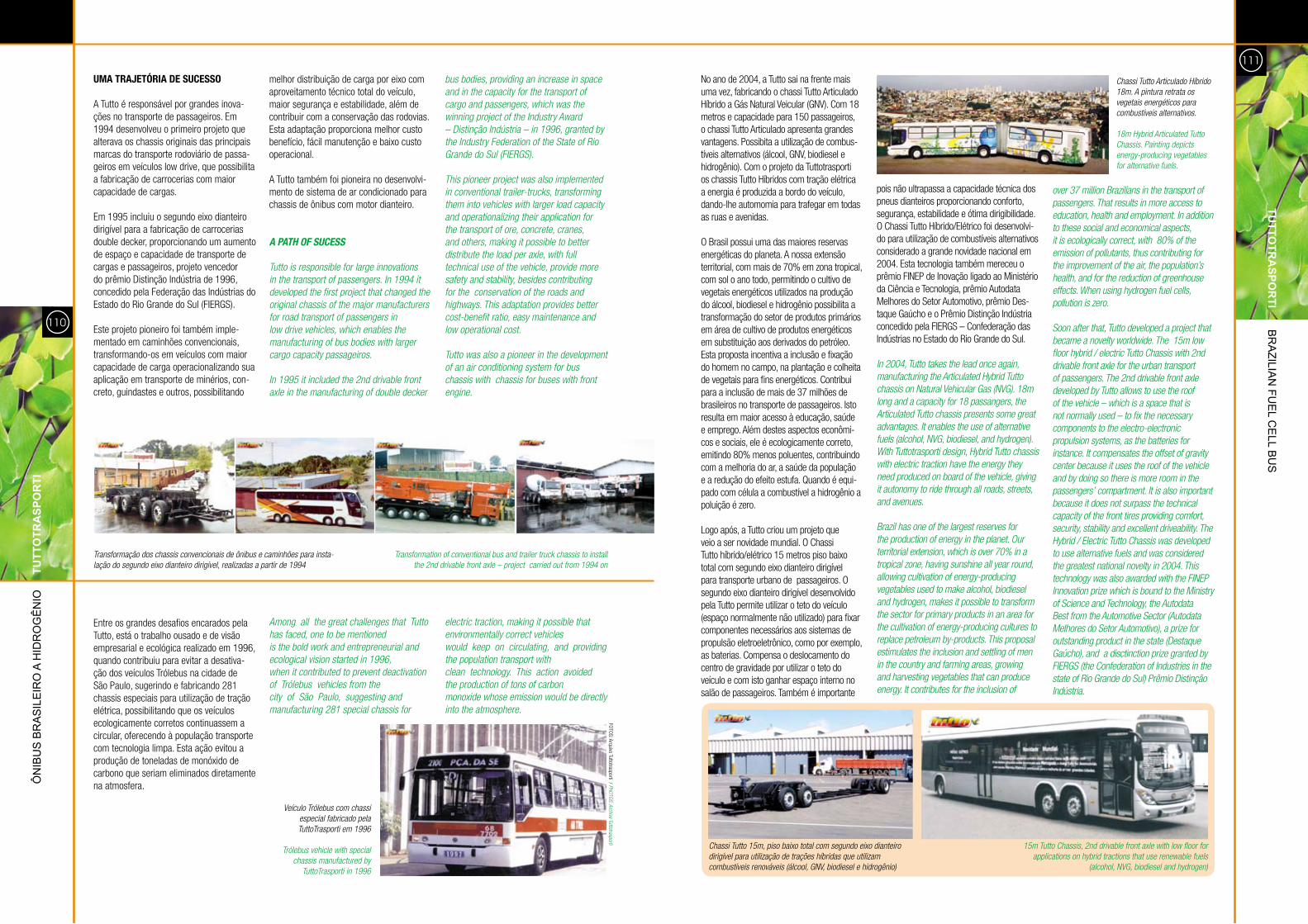
a Tutto é responsável por grandes inova-ções no transporte de passageiros. em 1994 desenvolveu o primeiro projeto que alterava os chassis originais das principais marcas do transporte rodoviário de passa-geiros em veículos low drive, que possibilita a fabricação de carrocerias com maior capacidade de cargas.
em 1995 incluiu o segundo eixo dianteiro dirigível para a fabricação de carrocerias double decker, proporcionando um aumento de espaço e capacidade de transporte de cargas e passageiros, projeto vencedor do prêmio distinção indústria de 1996, concedido pela Federação das indústrias do estado do Rio grande do sul (FieRgs). este projeto pioneiro foi também imple-mentado em caminhões convencionais, transformando-os em veículos com maior capacidade de carga operacionalizando sua aplicação em transporte de minérios, con-creto, guindastes e outros, possibilitando
melhor distribuição de carga por eixo com aproveitamento técnico total do veículo, maior segurança e estabilidade, além de contribuir com a conservação das rodovias. esta adaptação proporciona melhor custo benefício, fácil manutenção e baixo custo operacional.
a Tutto também foi pioneira no desenvolvi-mento de sistema de ar condicionado para chassis de ônibus com motor dianteiro.
A PATH OF SUCESS
Tutto is responsible for large innovations in the transport of passengers. In 1994 it developed the first project that changed the original chassis of the major manufacturers for road transport of passengers in low drive vehicles, which enables the manufacturing of bus bodies with larger cargo capacity passageiros.
In 1995 it included the 2nd drivable front axle in the manufacturing of double decker
bus bodies, providing an increase in space and in the capacity for the transport of cargo and passengers, which was the winning project of the Industry Award – distinção Indústria – in 1996, granted by the Industry Federation of the State of Rio Grande do Sul (FIERGS).
This pioneer project was also implemented in conventional trailer-trucks, transforming them into vehicles with larger load capacity and operationalizing their application for the transport of ore, concrete, cranes, and others, making it possible to better distribute the load per axle, with full technical use of the vehicle, provide more safety and stability, besides contributing for the conservation of the roads and highways. This adaptation provides better cost-benefit ratio, easy maintenance and low operational cost.
Tutto was also a pioneer in the development of an air conditioning system for bus chassis with chassis for buses with front engine.
entre os grandes desafios encarados pela Tutto, está o trabalho ousado e de visão empresarial e ecológica realizado em 1996, quando contribuiu para evitar a desativa-ção dos veículos Trólebus na cidade de são paulo, sugerindo e fabricando 281 chassis especiais para utilização de tração elétrica, possibilitando que os veículos ecologicamente corretos continuassem a circular, oferecendo à população transporte com tecnologia limpa. esta ação evitou a produção de toneladas de monóxido de carbono que seriam eliminados diretamente na atmosfera.
veículo Trólebus com chassi especial fabricado pela TuttoTrasporti em 1996
Trólebus vehicle with special chassis manufactured by
TuttoTrasporti in 1996
Transformação dos chassis convencionais de ônibus e caminhões para insta-lação do segundo eixo dianteiro dirigível, realizadas a partir de 1994
Transformation of conventional bus and trailer truck chassis to install the 2nd drivable front axle – project carried out from 1994 on
no ano de 2004, a Tutto sai na frente mais uma vez, fabricando o chassi Tutto articulado Híbrido a gás natural veicular (gnv). com 18 metros e capacidade para 150 passageiros, o chassi Tutto articulado apresenta grandes vantagens. possibita a utilização de combus-tíveis alternativos (álcool, gnv, biodiesel e hidrogênio). com o projeto da Tuttotrasporti os chassis Tutto Híbridos com tração elétrica a energia é produzida a bordo do veículo, dando-lhe automomia para trafegar em todas as ruas e avenidas.
o brasil possui uma das maiores reservas energéticas do planeta. a nossa extensão territorial, com mais de 70% em zona tropical, com sol o ano todo, permitindo o cultivo de vegetais energéticos utilizados na produção do álcool, biodiesel e hidrogênio possibilita a transformação do setor de produtos primários em área de cultivo de produtos energéticos em substituição aos derivados do petróleo. esta proposta incentiva a inclusão e fixação do homem no campo, na plantação e colheita de vegetais para fins energéticos. contribui para a inclusão de mais de 37 milhões de brasileiros no transporte de passageiros. isto resulta em maior acesso à educação, saúde e emprego. além destes aspectos econômi-cos e sociais, ele é ecologicamente correto, emitindo 80% menos poluentes, contribuindo com a melhoria do ar, a saúde da população e a redução do efeito estufa. Quando é equi-pado com célula a combustível a hidrogênio a poluição é zero.
logo após, a Tutto criou um projeto que veio a ser novidade mundial. o chassi Tutto híbrido/elétrico 15 metros piso baixo total com segundo eixo dianteiro dirigível para transporte urbano de passageiros. o segundo eixo dianteiro dirigível desenvolvido pela Tutto permite utilizar o teto do veículo (espaço normalmente não utilizado) para fixar componentes necessários aos sistemas de propulsão eletroeletrônico, como por exemplo, as baterias. compensa o deslocamento do centro de gravidade por utilizar o teto do veículo e com isto ganhar espaço interno no salão de passageiros. Também é importante
pois não ultrapassa a capacidade técnica dos pneus dianteiros proporcionando conforto, segurança, estabilidade e ótima dirigibilidade. o chassi Tutto Híbrido/elétrico foi desenvolvi-do para utilização de combustíveis alternativos considerado a grande novidade nacional em 2004. esta tecnologia também mereceu o prêmio Finep de inovação ligado ao Ministério da ciência e Tecnologia, prêmio autodata Melhores do setor automotivo, prêmio des-taque gaúcho e o prêmio distinção indústria concedido pela FieRgs – confederação das indústrias no estado do Rio grande do sul.
In 2004, Tutto takes the lead once again, manufacturing the Articulated Hybrid Tutto chassis on Natural vehicular Gas (NvG). 18m long and a capacity for 18 passangers, the Articulated Tutto chassis presents some great advantages. It enables the use of alternative fuels (alcohol, NvG, biodiesel, and hydrogen). With Tuttotrasporti design, Hybrid Tutto chassis with electric traction have the energy they need produced on board of the vehicle, giving it autonomy to ride through all roads, streets, and avenues.
Brazil has one of the largest reserves for the production of energy in the planet. Our territorial extension, which is over 70% in a tropical zone, having sunshine all year round, allowing cultivation of energy-producing vegetables used to make alcohol, biodiesel and hydrogen, makes it possible to transform the sector for primary products in an area for the cultivation of energy-producing cultures to replace petroleum by-products. This proposal estimulates the inclusion and settling of men in the country and farming areas, growing and harvesting vegetables that can produce energy. It contributes for the inclusion of
over 37 million Brazilians in the transport of passengers. That results in more access to education, health and employment. In addition to these social and economical aspects, it is ecologically correct, with 80% of the emission of pollutants, thus contributing for the improvement of the air, the population’s health, and for the reduction of greenhouse effects. When using hydrogen fuel cells, pollution is zero.
Soon after that, Tutto developed a project that became a novelty worldwide. The 15m low floor hybrid / electric Tutto Chassis with 2nd drivable front axle for the urban transport of passengers. The 2nd drivable front axle developed by Tutto allows to use the roof of the vehicle – which is a space that is not normally used – to fix the necessary components to the electro-electronic propulsion systems, as the batteries for instance. It compensates the offset of gravity center because it uses the roof of the vehicle and by doing so there is more room in the passengers’ compartment. It is also important because it does not surpass the technical capacity of the front tires providing comfort, security, stability and excellent driveability. The Hybrid / Electric Tutto Chassis was developed to use alternative fuels and was considered the greatest national novelty in 2004. This technology was also awarded with the FINEP Innovation prize which is bound to the Ministry of Science and Technology, the Autodata Best from the Automotive Sector (Autodata Melhores do Setor Automotivo), a prize for outstanding product in the state (destaque Gaúcho), and a disctinction prize granted by FIERGS (the Confederation of Industries in the state of Rio Grande do Sul) Prêmio distinção Indústria.
Chassi Tutto Articulado Híbrido 18m. A pintura retrata os vegetais energéticos para combustíveis alternativos.
18m Hybrid Articulated Tutto Chassis. Painting depicts energy-producing vegetables for alternative fuels.
Chassi Tutto 15m, piso baixo total com segundo eixo dianteiro dirigível para utilização de trações híbridas que utilizam combustíveis renováveis (álcool, GNv, biodiesel e hidrogênio)
Among all the great challenges that Tutto has faced, one to be mentionedis the bold work and entrepreneurial and ecological vision started in 1996,when it contributed to prevent deactivation of Trólebus vehicles from thecity of São Paulo, suggesting and manufacturing 281 special chassis for
electric traction, making it possible that environmentally correct vehicleswould keep on circulating, and providing the population transport withclean technology. This action avoided the production of tons of carbonmonoxide whose emission would be directly into the atmosphere.
15m Tutto Chassis, 2nd drivable front axle with low floor for applications on hybrid tractions that use renewable fuels
(alcohol, NvG, biodiesel and hydrogen)
FoTos: arquivo Tuttotrasporti / PHOTOS: Archive Tuttotrasporti
113
TUTTO
TRA
sPOR
TI br
azilia
n Fu
el C
ell b
us
PROJETO E FABRICAÇÃO DE CHASSI
o chassi usado neste veículo possui 12,6 metros de comprimento, piso baixo total com sistema de ajoelhamento, que facilita o embarque e desembarque de pessoas ido-sas e portadores de necessidades especiais além de suspensão pneumática integral.
para atender, as cargas dinâmicas e está-ticas causadas por todos os componentes presentes neste veículo, e os requisitos de performance necessários a um ônibus urbano, um chassi especial foi totalmente projetado e fabricado pela Tutto.
CHASSIS PROJECT AND MANUFACTURING
The chassis used on this vehicle is 12.6 meters long, with full low floor with kneeling system, which makes it easier for the elderly or the physically disabled to get on and off, in addition to a full pneumatic suspension.
In order to meet the needs from dynamic and static loads caused by all the components existing on this vehicle, as well as the performance requirements for a city bus, a special chassis was totally designed and manufactured by Tutto.
Chassi Tutto 12m com sistema de propulsão integrado
12m Tutto Chassis with integrated propulsion system
112
Ôn
ibu
s b
ra
sil
eir
o a
Hid
ro
gê
nio
T
UTT
OTR
AsP
OR
TI
INOVAÇÃO À TODA PROVA
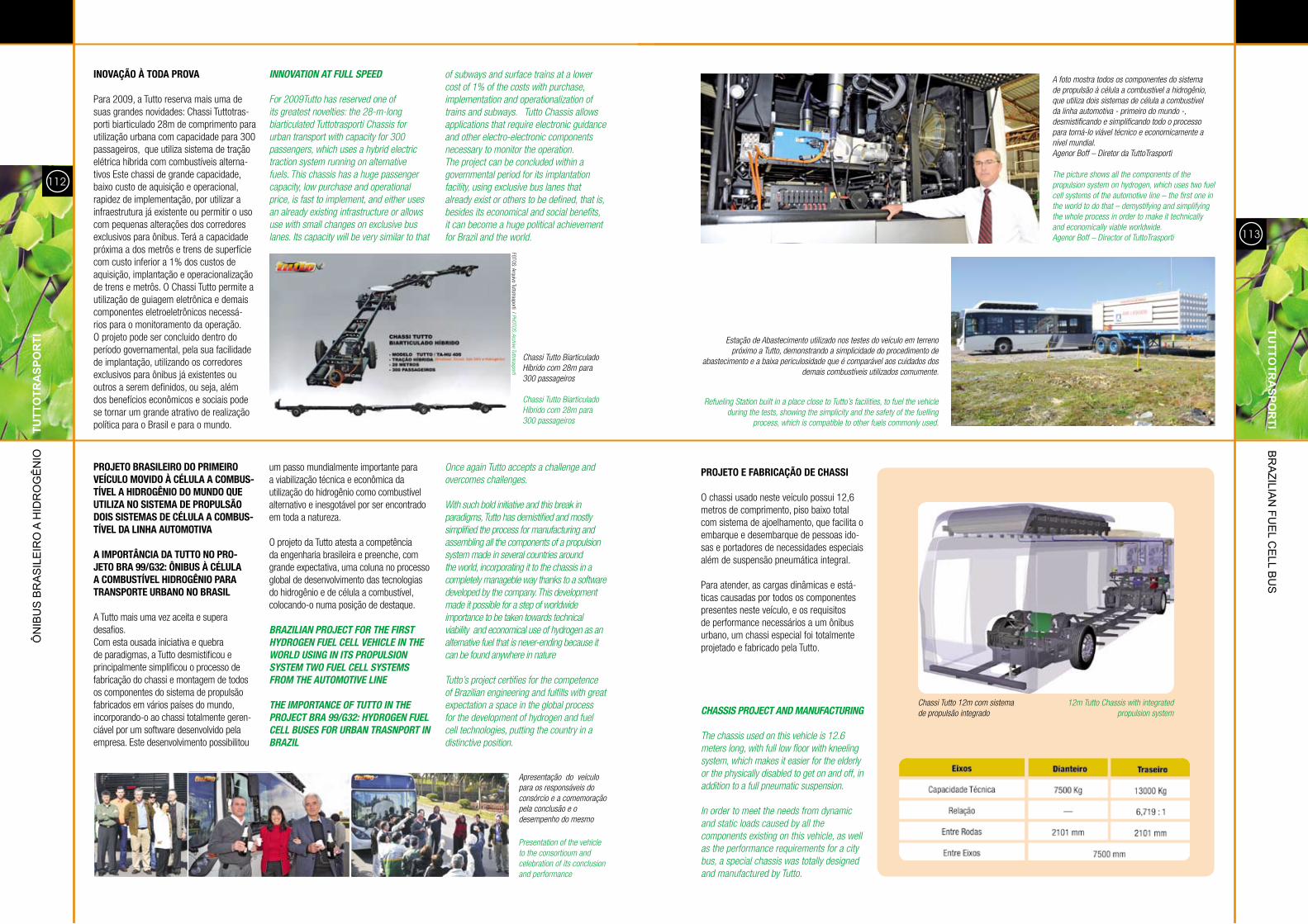
para 2009, a Tutto reserva mais uma de suas grandes novidades: chassi Tuttotras-porti biarticulado 28m de comprimento para utilização urbana com capacidade para 300 passageiros, que utiliza sistema de tração elétrica híbrida com combustíveis alterna-tivos este chassi de grande capacidade, baixo custo de aquisição e operacional, rapidez de implementação, por utilizar a infraestrutura já existente ou permitir o uso com pequenas alterações dos corredores exclusivos para ônibus. Terá a capacidade próxima a dos metrôs e trens de superfície com custo inferior a 1% dos custos de aquisição, implantação e operacionalização de trens e metrôs. o chassi Tutto permite a utilização de guiagem eletrônica e demais componentes eletroeletrônicos necessá-rios para o monitoramento da operação. o projeto pode ser concluido dentro do período governamental, pela sua facilidade de implantação, utilizando os corredores exclusivos para ônibus já existentes ou outros a serem definidos, ou seja, além dos benefícios econômicos e sociais pode se tornar um grande atrativo de realização política para o brasil e para o mundo.
INNOVATION AT FULL SPEED
For 2009Tutto has reserved one of its greatest novelties: the 28-m-long biarticulated Tuttotrasporti Chassis for urban transport with capacity for 300 passengers, which uses a hybrid electric traction system running on alternative fuels. This chassis has a huge passenger capacity, low purchase and operational price, is fast to implement, and either uses an already existing infrastructure or allows use with small changes on exclusive bus lanes. Its capacity will be very similar to that
of subways and surface trains at a lower cost of 1% of the costs with purchase, implementation and operationalization of trains and subways. Tutto Chassis allows applications that require electronic guidance and other electro-electronic components necessary to monitor the operation. The project can be concluded within a governmental period for its implantation facility, using exclusive bus lanes that already exist or others to be defined, that is, besides its economical and social benefits, it can become a huge political achievement for Brazil and the world.
Chassi Tutto Biarticulado Híbrido com 28m para 300 passageiros
Chassi Tutto Biarticulado Híbrido com 28m para 300 passageiros
PROJETO BRASILEIRO DO PRIMEIRO VEÍCULO MOVIDO À CÉLULA A COMBUS-TÍVEL A HIDROGÊNIO DO MUNDO QUE UTILIZA NO SISTEMA DE PROPULSÃO DOIS SISTEMAS DE CÉLULA A COMBUS-TÍVEL DA LINHA AUTOMOTIVA
A IMPORTÂNCIA DA TUTTO NO PRO-JETO BRA 99/G32: ÔNIBUS À CÉLULA A COMBUSTÍVEL HIDROGÊNIO PARA TRANSPORTE URBANO NO BRASIL
a Tutto mais uma vez aceita e supera desafios.com esta ousada iniciativa e quebra de paradigmas, a Tutto desmistificou e principalmente simplificou o processo de fabricação do chassi e montagem de todos os componentes do sistema de propulsão fabricados em vários países do mundo, incorporando-o ao chassi totalmente geren-ciável por um software desenvolvido pela empresa. este desenvolvimento possibilitou
um passo mundialmente importante para a viabilização técnica e econômica da utilização do hidrogênio como combustível alternativo e inesgotável por ser encontrado em toda a natureza.
o projeto da Tutto atesta a competência da engenharia brasileira e preenche, com grande expectativa, uma coluna no processo global de desenvolvimento das tecnologias do hidrogênio e de célula a combustível, colocando-o numa posição de destaque.
BRAZILIAN PROJECT FOR THE FIRST HYDROGEN FUEL CELL VEHICLE IN THE WORLD USING IN ITS PROPULSION SYSTEM TWO FUEL CELL SYSTEMS FROM THE AUTOMOTIVE LINE
THE IMPORTANCE OF TUTTO IN THE PROJECT BRA 99/G32: HYDROGEN FUEL CELL BUSES FOR URBAN TRASNPORT IN BRAZIL
Once again Tutto accepts a challenge and overcomes challenges.
With such bold initiative and this break in paradigms, Tutto has demistified and mostly simplified the process for manufacturing and assembling all the components of a propulsion system made in several countries around the world, incorporating it to the chassis in a completely manageble way thanks to a software developed by the company. This development made it possible for a step of worldwide importance to be taken towards technical viability and economical use of hydrogen as an alternative fuel that is never-ending because it can be found anywhere in nature
Tutto’s project certifies for the competence of Brazilian engineering and fulfills with great expectation a space in the global process for the development of hydrogen and fuel cell technologies, putting the country in a distinctive position.
Presentation of the vehicle to the consortioum and celebration of its conclusion and performance
A foto mostra todos os componentes do sistema de propulsão à célula a combustível a hidrogênio, que utiliza dois sistemas de célula a combustível da linha automotiva - primeiro do mundo -, desmistificando e simplificando todo o processo para torná-lo viável técnico e economicamente a nível mundial.Agenor Boff – diretor da TuttoTrasporti
The picture shows all the components of the propulsion system on hydrogen, which uses two fuel cell systems of the automotive line – the first one in the world to do that – demystifying and simplifying the whole process in order to make it technically and economically viable worldwide.Agenor Boff – director of TuttoTrasporti
Estação de Abastecimento utilizado nos testes do veículo em terreno próximo a Tutto, demonstrando a simplicidade do procedimento de
abastecimento e a baixa periculosidade que é comparável aos cuidados dos demais combustíveis utilizados comumente.
Apresentação do veículo para os responsáveis doconsórcio e a comemoração pela conclusão e o desempenho do mesmo
Refueling Station built in a place close to Tutto’s facilities, to fuel the vehicle during the tests, showing the simplicity and the safety of the fuelling
process, which is compatible to other fuels commonly used.
FoTos: arquivo Tuttotrasporti / PHOTOS: Archive Tuttotrasporti
Simulação de tensões sofridas pela estrutura do chassi em condição de curva.
Chassi em fase de fabricação.
Simulation for tension suffered by the chassis structure under curve conditions.
Chassis being manufactured.115
TUTTO
TRA
sPOR
TI br
azilia
n Fu
el C
ell b
us
114
Ôn
ibu
s b
ra
sil
eir
o a
Hid
ro
gê
nio
T
UTT
OTR
AsP
OR
TI
LAyOUT DO COMPARTIMENTO DO MO-TOR OU “PACKAGING”
os volumes e o número elevado de componentes é um problema que precisa ser resolvido para atender a compromissos importantes como a compactação, eficiên-cia nas interconectividades entre sistemas, segurança, distribuição de peso e o acesso facilitado para manutenção. a configuração utilizada nesse veículo, por se tratar do primeiro protótipo, teve como prioridades a simplicidade das interconexões, seguran-ça, acesso facilitado para manutenção e a distribuição de peso. a compactação e redução do volume do compartimento do motor terão prioridade aumentada na segunda fase do projeto.
a base desse desenvolvimento é resultado da experiência acumulada ao longo de 20 anos em adaptações de chassis, para di-versas aplicações especiais, e do emprego de ferramentas modernas de engenharia como cad e cae.
LAYOUT OF THE ENGINE COMPARTMENT OR “PACKAGING”
volumes and the large number of components is a problem that needs to be solved in order to meet important requirements, such as compaction, efficiency in the interconnectivity among systems, security, weight distribution and easy access for maintenance and servicing. The configuration used on this vehicle – because it is a first prototype – prioritized on the simplicity of the interconnections, on safety, easy access for maintenance purposes and weight distribution.
Compacting and reducing volume of the engine compartment will be prioritized on the second phase of the project.
The basis for this development is the result of experience accumulated over a period of 20 years dedicated to adaptations of chassis, for the most diverse applications, and for the use of modern engineering tools, such as CAd and CAE.
Projeto de dispositivo para instalação e manutenção das células a combustível.
Project for an installation and maintenance device for the fuel cells.
Lay-out ou “Packaging” do compartimento do motor. Lay-out or “Packaging” for the engine compartment
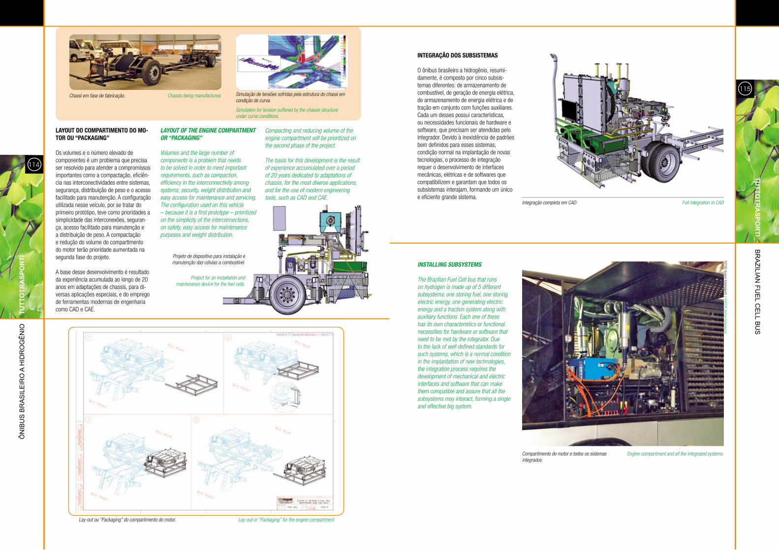
INTEGRAÇÃO DOS SUBSISTEMAS
o ônibus brasileiro a hidrogênio, resumi-damente, é composto por cinco subsis-temas diferentes: de armazenamento de combustível, de geração de energia elétrica, de armazenamento de energia elétrica e de tração em conjunto com funções auxiliares. cada um desses possui características, ou necessidades funcionais de hardware e software, que precisam ser atendidas pelo integrador. devido à inexistência de padrões bem definidos para esses sistemas, condição normal na implantação de novas tecnologias, o processo de integração requer o desenvolvimento de interfaces mecânicas, elétricas e de softwares que compatibilizem e garantam que todos os subsistemas interajam, formando um único e eficiente grande sistema.
INSTALLING SUBSYSTEMS
The Brazilian Fuel Cell bus that runs on hydrogen is made up of 5 different subsystems: one storing fuel, one storing electric energy, one generating electric energy and a traction system along with auxiliary functions. Each one of these has its own characteristics or functional necessities for hardware or software that need to be met by the integrator. due to the lack of well defined standards for such systems, which is a normal condition in the implantation of new technologies, the integration process requires the development of mechanical and electric interfaces and software that can make them compatible and assure that all the subsystems may interact, forming a single and effective big system.
Integração completa em CAd
Compartimento do motor e todos os sistemas integrados.
Full integration in CAd
Engine compartment and all the integrated systems.
FoTos: arquivo Tuttotrasporti / PHOTOS: Archive Tuttotrasporti
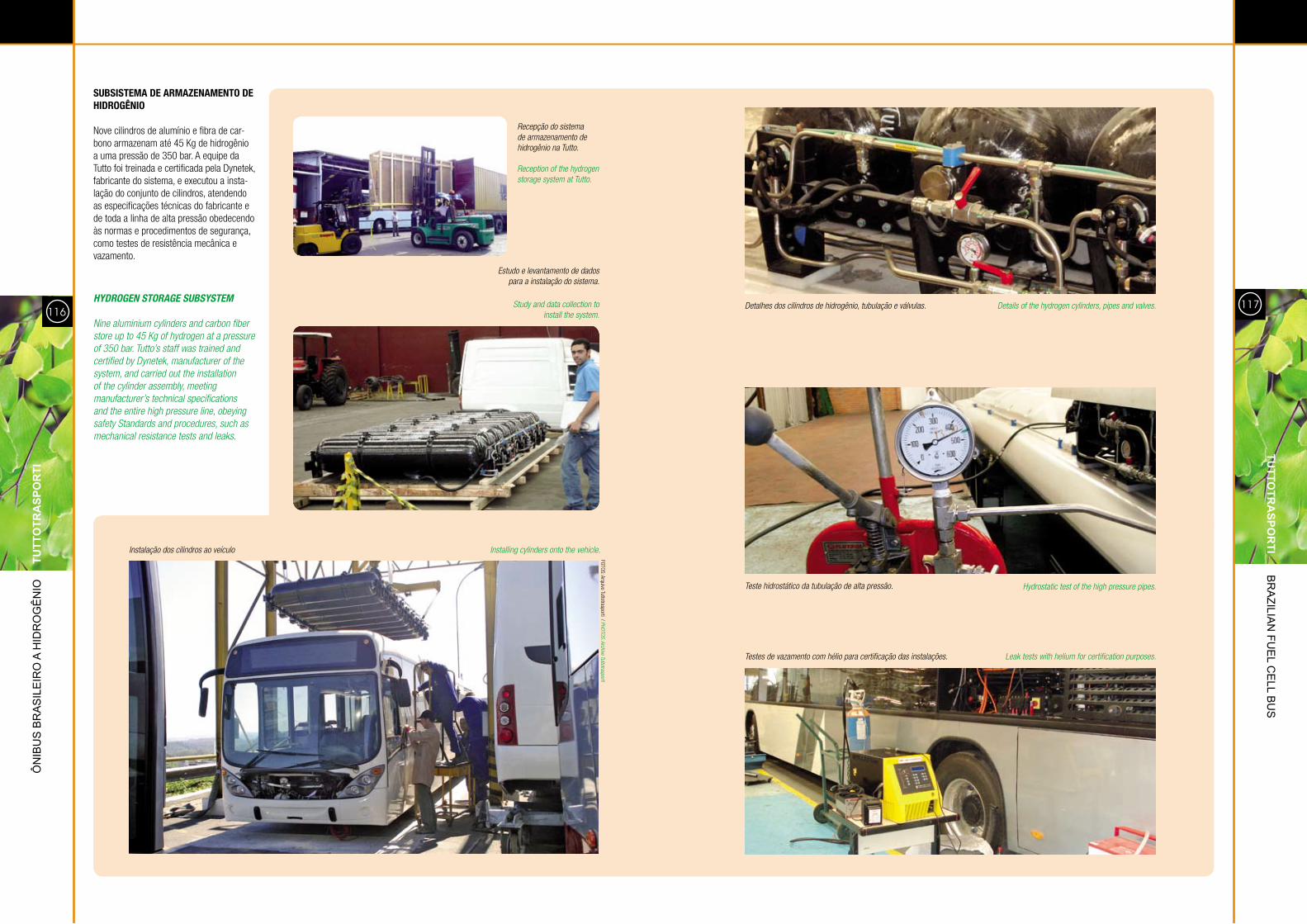
SUBSISTEMA DE ARMAZENAMENTO DE HIDROGÊNIO
nove cilindros de alumínio e fibra de car-bono armazenam até 45 Kg de hidrogênio a uma pressão de 350 bar. a equipe da Tutto foi treinada e certificada pela dynetek, fabricante do sistema, e executou a insta-lação do conjunto de cilindros, atendendo as especificações técnicas do fabricante e de toda a linha de alta pressão obedecendo às normas e procedimentos de segurança, como testes de resistência mecânica e vazamento.
HYDROGEN STORAGE SUBSYSTEM
Nine aluminium cylinders and carbon fiber store up to 45 Kg of hydrogen at a pressure of 350 bar. Tutto’s staff was trained and certified by dynetek, manufacturer of the system, and carried out the installation of the cylinder assembly, meeting manufacturer’s technical specifications and the entire high pressure line, obeying safety Standards and procedures, such as mechanical resistance tests and leaks.
Recepção do sistema de armazenamento de hidrogênio na Tutto.
Reception of the hydrogen storage system at Tutto.
Estudo e levantamento de dados para a instalação do sistema.
Study and data collection to install the system.
Instalação dos cilindros ao veículo Installing cylinders onto the vehicle.
detalhes dos cilindros de hidrogênio, tubulação e válvulas.
Teste hidrostático da tubulação de alta pressão.
Testes de vazamento com hélio para certificação das instalações.
details of the hydrogen cylinders, pipes and valves.
Hydrostatic test of the high pressure pipes.
Leak tests with helium for certification purposes.
117
TUTTO
TRA
sPOR
TI br
azilia
n Fu
el C
ell b
us
116
Ôn
ibu
s b
ra
sil
eir
o a
Hid
ro
gê
nio
T
UTT
OTR
AsP
OR
TI
FoTos: arquivo Tuttotrasporti / PHOTOS: Archive Tuttotrasporti
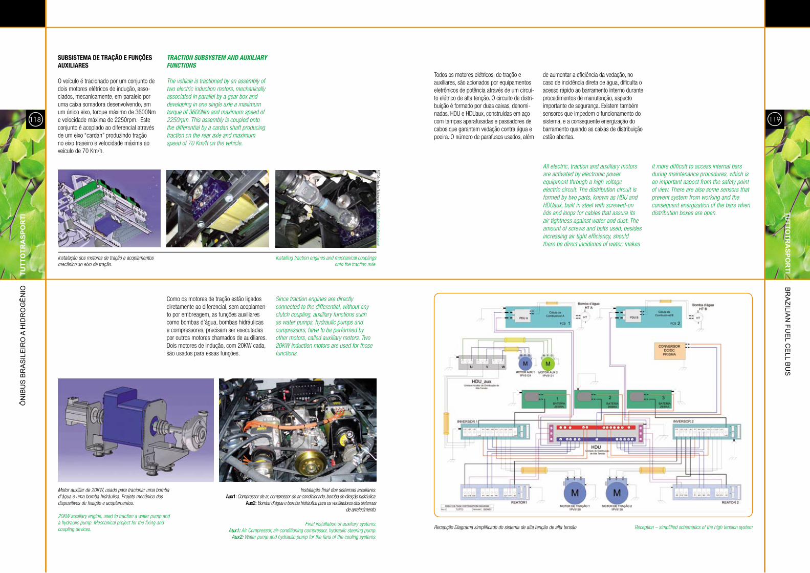
SUBSISTEMA DE TRAÇÃO E FUNÇÕES AUXILIARES
o veículo é tracionado por um conjunto de dois motores elétricos de indução, asso-ciados, mecanicamente, em paralelo por uma caixa somadora desenvolvendo, em um único eixo, torque máximo de 3600nm e velocidade máxima de 2250rpm. este conjunto é acoplado ao diferencial através de um eixo “cardan” produzindo tração no eixo traseiro e velocidade máxima ao veículo de 70 Km/h.
TRACTION SUBSYSTEM AND AUXILIARY FUNCTIONS
The vehicle is tractioned by an assembly of two electric induction motors, mechanically associated in parallel by a gear box and developing in one single axle a maximum torque of 3600Nm and maximum speed of 2250rpm. This assembly is coupled onto the differential by a cardan shaft producing traction on the rear axle and maximum speed of 70 Km/h on the vehicle.
Motor auxiliar de 20KW, usado para tracionar uma bomba d’água e uma bomba hidráulica. Projeto mecânico dos dispositivos de fixação e acoplamentos.
20KW auxiliary engine, used to traction a water pump and a hydraulic pump. Mechanical project for the fixing and coupling devices.
Instalação dos motores de tração e acoplamentos mecânico ao eixo de tração.
como os motores de tração estão ligados diretamente ao diferencial, sem acoplamen-to por embreagem, as funções auxiliares como bombas d’água, bombas hidráulicas e compressores, precisam ser executadas por outros motores chamados de auxiliares. dois motores de indução, com 20KW cada, são usados para essas funções.
Since traction engines are directly connected to the differential, without any clutch coupling, auxiliary functions such as water pumps, hydraulic pumps and compressors, have to be performed by other motors, called auxiliary motors. Two 20KW induction motors are used for those functions.
Installing traction engines and mechanical couplings onto the traction axle.
Instalação final dos sistemas auxiliares.aux1: Compressor de ar, compressor de ar-condicionado, bomba de direção hidráulica.
aux2: Bomba d’água e bomba hidráulica para os ventiladores dos sistemas de arrefecimento.
Final installation of auxiliary systems.Aux1: Air Compressor, air-conditioning compressor, hydraulic steering pump.
Aux2: Water pump and hydraulic pump for the fans of the cooling systems.
Todos os motores elétricos, de tração e auxiliares, são acionados por equipamentos eletrônicos de potência através de um circui-to elétrico de alta tenção. o circuito de distri-buição é formado por duas caixas, denomi-nadas, HdU e HdUaux, construídas em aço com tampas aparafusadas e passadores de cabos que garantem vedação contra água e poeira. o número de parafusos usados, além
de aumentar a eficiência da vedação, no caso de incidência direta de água, dificulta o acesso rápido ao barramento interno durante procedimentos de manutenção, aspecto importante de segurança. existem também sensores que impedem o funcionamento do sistema, e a consequente energização do barramento quando as caixas de distribuição estão abertas.
All electric, traction and auxiliary motors are activated by electronic power equipment through a high voltage electric circuit. The distribution circuit is formed by two parts, known as HdU and HdUaux, built in steel with screwed-on lids and loops for cables that assure its air tightness against water and dust. The amount of screws and bolts used, besides increasing air tight efficiency, should there be direct incidence of water, makes
it more difficult to access internal bars during maintenance procedures, which is an important aspect from the safety point of view. There are also some sensors that prevent system from working and the consequent energization of the bars when distribution boxes are open.
Reception – simplified schematics of the high tension systemRecepção diagrama simplificado do sistema de alta tenção de alta tensão
119
TUTTO
TRA
sPOR
TI br
azilia
n Fu
el C
ell b
us
118
Ôn
ibu
s b
ra
sil
eir
o a
Hid
ro
gê
nio
T
UTT
OTR
AsP
OR
TI
FoTos: arquivo Tuttotrasporti / PHOTOS: Archive Tuttotrasporti


![Projeto%20de%20 inclus%c3%a3o%20digital%20na%20terceira%20idade%2009.07.2010[1][1]](https://img.pdfslide.tips/doc/110x75/55948aa11a28ab177d8b47aa/projeto20de20-inclusc3a3o20digital20na20terceira20idade200907201011.jpg)