Embed Size (px)
Citation preview
IJSRD - International Journal for Scientific Research & Development| Vol. 3, Issue 11, 2016 | ISSN (online): 2321-0613
All rights reserved by www.ijsrd.com 260
Design and Analysis of Thin-Rimmed Gears using Finite Element
Modelling Sachin Dholya1 Rohit Rajvaidya2
1,2Department of Mechanical Engineering 1,2University Institute of Technology, BU, Bhopal
Abstract— In present day’s applications it is more and more
significant to minimize space and material saving gears with
wide applications in general machines for weight reduction
and compact design. One option is to design the rim of gears
as thin as possible in order to reduce maximum space.
Design of thin rimmed gears for strength is the prime aim in
order to bear high rotational speeds under harsh conditions.
In present work, some studies relevant to finite element
modelling and finite element analysis of thin rimmed gears
are performed. These studies will assist in prospects and
concerns of the thin-rimmed gears while designing them for
moderate loading and with cost effectiveness. Finite element
studies for static structural analysis, modal analysis and
contact analysis simulating real-time conditions are
presented.
Key words: Finite Element Analysis, Contact Analysis,
Structural Analysis, Thin Rimmed Gears, Vibration
Analysis
I. INTRODUCTION
Gearboxes are employed in every kind of machinery,
ranging from a toy car motor to heavy equipment
assemblies, from machines to automotive to the aerospace
engines. Among the gears, spurs gear most commonly used
gears. In current day’s scenario, it is more and more
significant to minimize space and material saving gears with
wide applications in general machines for weight reduction
and compact design. Though, the spur gears have been
standardized for the profile requirements, the material
reduction for the gear can be done if a rimed gear instead of
a standard full gear is used. This goes along with a
meaningfully greater deployment of the material strength
against tooth root fracture. Tooth root failure can happen
suddenly without much response time in comparison to wear
and pitting. With increased demands for higher performance
of gear units the load capacity of gears is a matter of great
concern. In order to achieve design goals like reduced
weight the rim and web of gears are often design thin.
Planetary thin rimmed gear sets are used commonly by
automotive and aerospace industries [1]. Typical
applications include jet propulsion systems, rotorcraft
transmissions, passenger vehicle automatic transmissions
and transfer cases and off-highway vehicle gearboxes.
Timmins has highlighted that most machine failures are
related to mechanical transmission systems such as gears
and bearings [2]. To date, a series of effective investigations
have been conducted for gear. Now a question appears how
to perform strength analysis of the thin-rimmed inclined
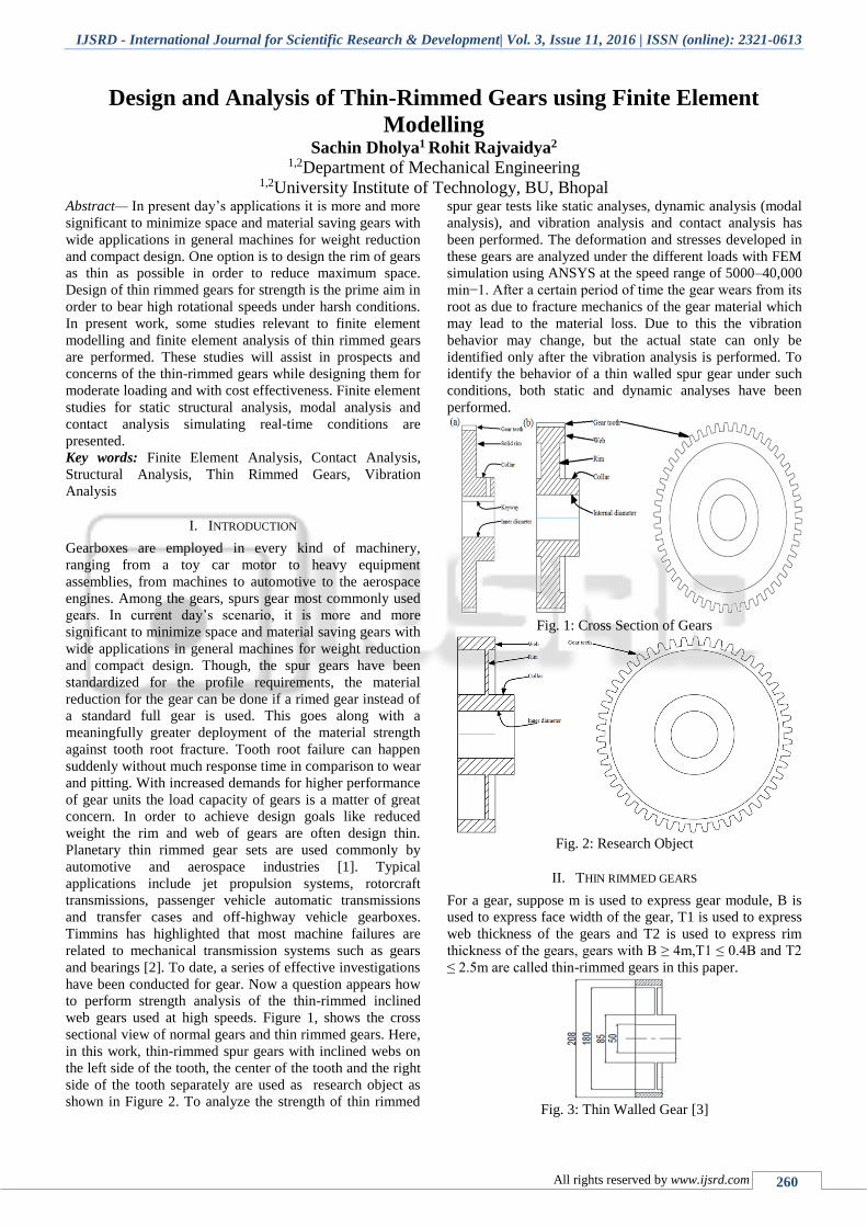
web gears used at high speeds. Figure 1, shows the cross
sectional view of normal gears and thin rimmed gears. Here,
in this work, thin-rimmed spur gears with inclined webs on
the left side of the tooth, the center of the tooth and the right
side of the tooth separately are used as research object as
shown in Figure 2. To analyze the strength of thin rimmed
spur gear tests like static analyses, dynamic analysis (modal
analysis), and vibration analysis and contact analysis has
been performed. The deformation and stresses developed in
these gears are analyzed under the different loads with FEM
simulation using ANSYS at the speed range of 5000–40,000
min−1. After a certain period of time the gear wears from its
root as due to fracture mechanics of the gear material which
may lead to the material loss. Due to this the vibration
behavior may change, but the actual state can only be
identified only after the vibration analysis is performed. To
identify the behavior of a thin walled spur gear under such
conditions, both static and dynamic analyses have been
performed.
Fig. 1: Cross Section of Gears
Fig. 2: Research Object
II. THIN RIMMED GEARS
For a gear, suppose m is used to express gear module, B is
used to express face width of the gear, T1 is used to express
web thickness of the gears and T2 is used to express rim
thickness of the gears, gears with B ≥ 4m,T1 ≤ 0.4B and T2
≤ 2.5m are called thin-rimmed gears in this paper.
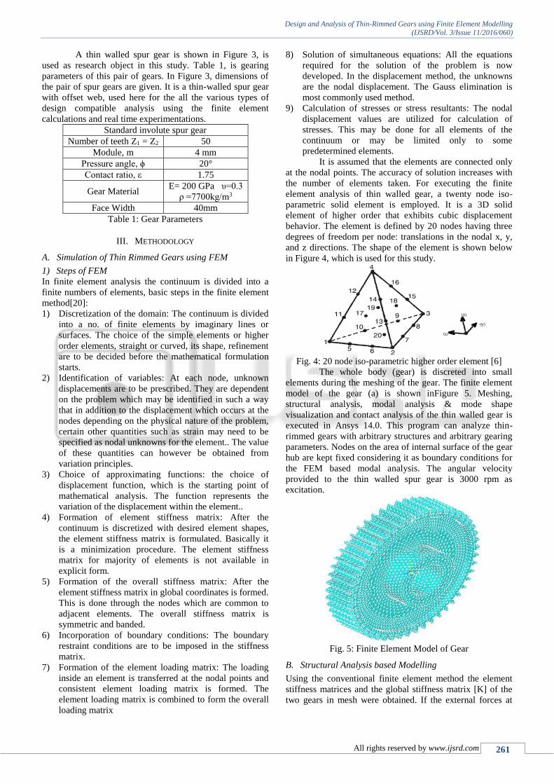
Fig. 3: Thin Walled Gear [3]
Design and Analysis of Thin-Rimmed Gears using Finite Element Modelling
(IJSRD/Vol. 3/Issue 11/2016/060)
All rights reserved by www.ijsrd.com 261
A thin walled spur gear is shown in Figure 3, is
used as research object in this study. Table 1, is gearing
parameters of this pair of gears. In Figure 3, dimensions of
the pair of spur gears are given. It is a thin-walled spur gear
with offset web, used here for the all the various types of
design compatible analysis using the finite element
calculations and real time experimentations.
Standard involute spur gear
Number of teeth Z1 = Z2 50
Module, m 4 mm
Pressure angle, ϕ 20°
Contact ratio, ε 1.75
Gear Material E= 200 GPa υ=0.3
ρ =7700kg/m3
Face Width 40mm
Table 1: Gear Parameters
III. METHODOLOGY
A. Simulation of Thin Rimmed Gears using FEM
1) Steps of FEM
In finite element analysis the continuum is divided into a
finite numbers of elements, basic steps in the finite element
method[20]:
1) Discretization of the domain: The continuum is divided
into a no. of finite elements by imaginary lines or
surfaces. The choice of the simple elements or higher
order elements, straight or curved, its shape, refinement
are to be decided before the mathematical formulation
starts.
2) Identification of variables: At each node, unknown
displacements are to be prescribed. They are dependent
on the problem which may be identified in such a way
that in addition to the displacement which occurs at the
nodes depending on the physical nature of the problem,
certain other quantities such as strain may need to be
specified as nodal unknowns for the element.. The value
of these quantities can however be obtained from
variation principles.
3) Choice of approximating functions: the choice of
displacement function, which is the starting point of
mathematical analysis. The function represents the
variation of the displacement within the element..
4) Formation of element stiffness matrix: After the
continuum is discretized with desired element shapes,
the element stiffness matrix is formulated. Basically it
is a minimization procedure. The element stiffness
matrix for majority of elements is not available in
explicit form.
5) Formation of the overall stiffness matrix: After the
element stiffness matrix in global coordinates is formed.
This is done through the nodes which are common to
adjacent elements. The overall stiffness matrix is
symmetric and banded.
6) Incorporation of boundary conditions: The boundary
restraint conditions are to be imposed in the stiffness
matrix.
7) Formation of the element loading matrix: The loading
inside an element is transferred at the nodal points and
consistent element loading matrix is formed. The
element loading matrix is combined to form the overall
loading matrix
8) Solution of simultaneous equations: All the equations
required for the solution of the problem is now
developed. In the displacement method, the unknowns
are the nodal displacement. The Gauss elimination is
most commonly used method.
9) Calculation of stresses or stress resultants: The nodal
displacement values are utilized for calculation of
stresses. This may be done for all elements of the
continuum or may be limited only to some
predetermined elements.
It is assumed that the elements are connected only
at the nodal points. The accuracy of solution increases with
the number of elements taken. For executing the finite
element analysis of thin walled gear, a twenty node iso-
parametric solid element is employed. It is a 3D solid
element of higher order that exhibits cubic displacement
behavior. The element is defined by 20 nodes having three
degrees of freedom per node: translations in the nodal x, y,
and z directions. The shape of the element is shown below
in Figure 4, which is used for this study.
Fig. 4: 20 node iso-parametric higher order element [6]
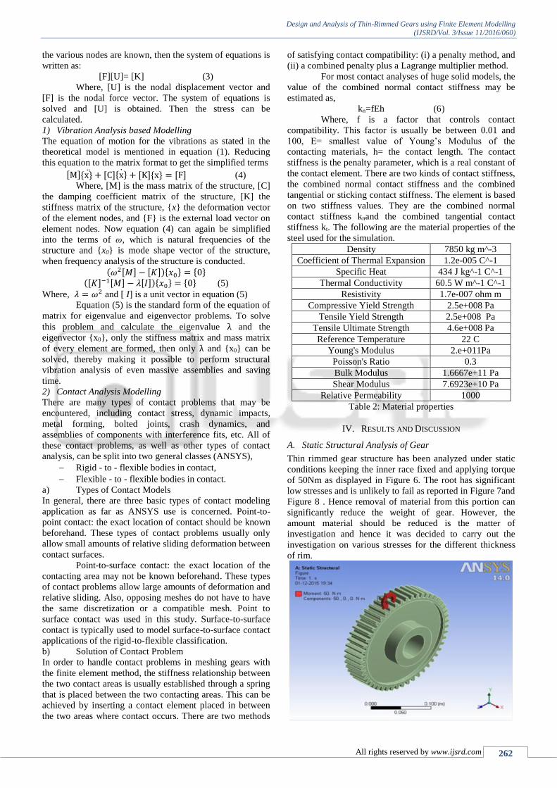
The whole body (gear) is discreted into small
elements during the meshing of the gear. The finite element
model of the gear (a) is shown inFigure 5. Meshing,
structural analysis, modal analysis & mode shape
visualization and contact analysis of the thin walled gear is
executed in Ansys 14.0. This program can analyze thin-
rimmed gears with arbitrary structures and arbitrary gearing
parameters. Nodes on the area of internal surface of the gear
hub are kept fixed considering it as boundary conditions for
the FEM based modal analysis. The angular velocity
provided to the thin walled spur gear is 3000 rpm as
excitation.
Fig. 5: Finite Element Model of Gear
B. Structural Analysis based Modelling
Using the conventional finite element method the element
stiffness matrices and the global stiffness matrix [K] of the
two gears in mesh were obtained. If the external forces at
Design and Analysis of Thin-Rimmed Gears using Finite Element Modelling
(IJSRD/Vol. 3/Issue 11/2016/060)
All rights reserved by www.ijsrd.com 262
the various nodes are known, then the system of equations is
written as:
[F][U]= [K] (3)
Where, [U] is the nodal displacement vector and
[F] is the nodal force vector. The system of equations is
solved and [U] is obtained. Then the stress can be
calculated.
1) Vibration Analysis based Modelling
The equation of motion for the vibrations as stated in the
theoretical model is mentioned in equation (1). Reducing
this equation to the matrix format to get the simplified terms
[M]{x}̈ + [C]{x}̇ + [K]{x} = [F] (4)
Where, [M] is the mass matrix of the structure, [C]
the damping coefficient matrix of the structure, [K] the
stiffness matrix of the structure, {x} the deformation vector
of the element nodes, and {F} is the external load vector on
element nodes. Now equation (4) can again be simplified
into the terms of ω, which is natural frequencies of the
structure and {x0} is mode shape vector of the structure,
when frequency analysis of the structure is conducted.
(𝜔2[𝑀] − [𝐾]){𝑥0} = {0} ([𝐾]−1[𝑀] − 𝜆[𝐼]){𝑥0} = {0} (5)
Where, 𝜆 = 𝜔2 and [ I] is a unit vector in equation (5)
Equation (5) is the standard form of the equation of
matrix for eigenvalue and eigenvector problems. To solve
this problem and calculate the eigenvalue λ and the
eigenvector {x0}, only the stiffness matrix and mass matrix
of every element are formed, then only λ and {x0} can be
solved, thereby making it possible to perform structural
vibration analysis of even massive assemblies and saving
time.
2) Contact Analysis Modelling
There are many types of contact problems that may be
encountered, including contact stress, dynamic impacts,
metal forming, bolted joints, crash dynamics, and
assemblies of components with interference fits, etc. All of
these contact problems, as well as other types of contact
analysis, can be split into two general classes (ANSYS),
Rigid - to - flexible bodies in contact,
Flexible - to - flexible bodies in contact.
a) Types of Contact Models
In general, there are three basic types of contact modeling
application as far as ANSYS use is concerned. Point-to-
point contact: the exact location of contact should be known
beforehand. These types of contact problems usually only
allow small amounts of relative sliding deformation between
contact surfaces.
Point-to-surface contact: the exact location of the
contacting area may not be known beforehand. These types
of contact problems allow large amounts of deformation and
relative sliding. Also, opposing meshes do not have to have
the same discretization or a compatible mesh. Point to
surface contact was used in this study. Surface-to-surface
contact is typically used to model surface-to-surface contact
applications of the rigid-to-flexible classification.
b) Solution of Contact Problem
In order to handle contact problems in meshing gears with
the finite element method, the stiffness relationship between
the two contact areas is usually established through a spring
that is placed between the two contacting areas. This can be
achieved by inserting a contact element placed in between
the two areas where contact occurs. There are two methods
of satisfying contact compatibility: (i) a penalty method, and
(ii) a combined penalty plus a Lagrange multiplier method.
For most contact analyses of huge solid models, the
value of the combined normal contact stiffness may be
estimated as,
kn=fEh (6)
Where, f is a factor that controls contact
compatibility. This factor is usually be between 0.01 and
100, E= smallest value of Young’s Modulus of the
contacting materials, h= the contact length. The contact
stiffness is the penalty parameter, which is a real constant of
the contact element. There are two kinds of contact stiffness,
the combined normal contact stiffness and the combined
tangential or sticking contact stiffness. The element is based
on two stiffness values. They are the combined normal
contact stiffness knand the combined tangential contact
stiffness kt. The following are the material properties of the
steel used for the simulation.
Density 7850 kg m^-3
Coefficient of Thermal Expansion 1.2e-005 C^-1
Specific Heat 434 J kg^-1 C^-1
Thermal Conductivity 60.5 W m^-1 C^-1
Resistivity 1.7e-007 ohm m
Compressive Yield Strength 2.5e+008 Pa
Tensile Yield Strength 2.5e+008 Pa
Tensile Ultimate Strength 4.6e+008 Pa
Reference Temperature 22 C
Young's Modulus 2.e+011Pa
Poisson's Ratio 0.3
Bulk Modulus 1.6667e+11 Pa
Shear Modulus 7.6923e+10 Pa
Relative Permeability 1000
Table 2: Material properties
IV. RESULTS AND DISCUSSION
A. Static Structural Analysis of Gear
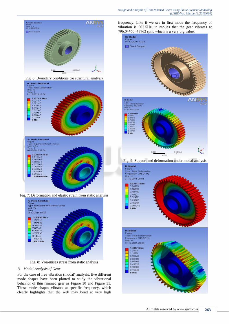
Thin rimmed gear structure has been analyzed under static
conditions keeping the inner race fixed and applying torque
of 50Nm as displayed in Figure 6. The root has significant
low stresses and is unlikely to fail as reported in Figure 7and
Figure 8 . Hence removal of material from this portion can
significantly reduce the weight of gear. However, the
amount material should be reduced is the matter of
investigation and hence it was decided to carry out the
investigation on various stresses for the different thickness
of rim.
Design and Analysis of Thin-Rimmed Gears using Finite Element Modelling
(IJSRD/Vol. 3/Issue 11/2016/060)
All rights reserved by www.ijsrd.com 263
Fig. 6: Boundary conditions for structural analysis
Fig. 7: Deformation and elastic strain from static analysis
Fig. 8: Von-mises stress from static analysis
B. Modal Analysis of Gear
For the case of free vibration (modal) analysis, five different
mode shapes have been plotted to study the vibrational
behavior of thin rimmed gear as Figure 10 and Figure 11.
These mode shapes vibrates at specific frequency, which
clearly highlights that the web may bend at very high
frequency. Like if we see in first mode the frequency of
vibration is 502.5Hz, it implies that the gear vibrates at
796.04*60≈47762 rpm, which is a very big value.
Fig. 9: Support and deformation under modal analysis
Design and Analysis of Thin-Rimmed Gears using Finite Element Modelling
(IJSRD/Vol. 3/Issue 11/2016/060)
All rights reserved by www.ijsrd.com 264
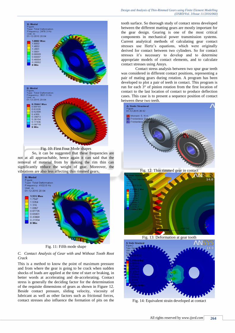
Fig. 10: First Four Mode shapes
So, it can be suggested that these frequencies are
not at all approachable, hence again it can said that the
removal of material from by making the rim thin can
significantly reduce the weight of gear. Moreover, the
vibrations are also less affecting thin rimmed gears.
Fig. 11: Fifth mode shape
C. Contact Analysis of Gear with and Without Tooth Root
Crack
This is a method to know the point of maximum pressure
and from where the gear is going to be crack when sudden
shocks of loads are applied at the time of start or braking, in
better words at accelerating and de-accelerating. Contact
stress is generally the deciding factor for the determination
of the requisite dimensions of gears as shown in Figure 12.
Beside contact pressure, sliding velocity, viscosity of
lubricant as well as other factors such as frictional forces,
contact stresses also influence the formation of pits on the
tooth surface. So thorough study of contact stress developed
between the different matting gears are mostly important for
the gear design. Gearing is one of the most critical
components in mechanical power transmission systems.
Current analytical methods of calculating gear contact
stresses use Hertz’s equations, which were originally
derived for contact between two cylinders. So for contact
stresses it’s necessary to develop and to determine
appropriate models of contact elements, and to calculate
contact stresses using Ansys.
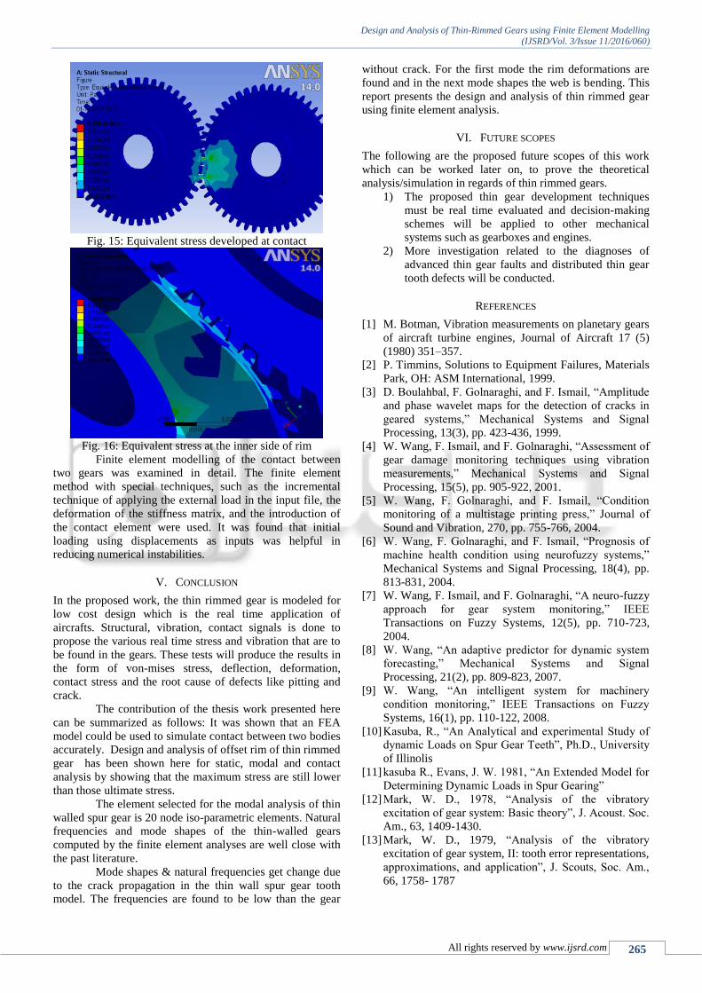
Contact stress analysis between two spur gear teeth
was considered in different contact positions, representing a
pair of mating gears during rotation. A program has been
developed to plot a pair of teeth in contact. This program is
run for each 3° of pinion rotation from the first location of
contact to the last location of contact to produce deflection
cases. This case is to present a sequence position of contact
between these two teeth.
Fig. 12: Thin rimmed gear in contact
Fig. 13: Deformation at gear tooth
Fig. 14: Equivalent strain developed at contact
Design and Analysis of Thin-Rimmed Gears using Finite Element Modelling
(IJSRD/Vol. 3/Issue 11/2016/060)
All rights reserved by www.ijsrd.com 265
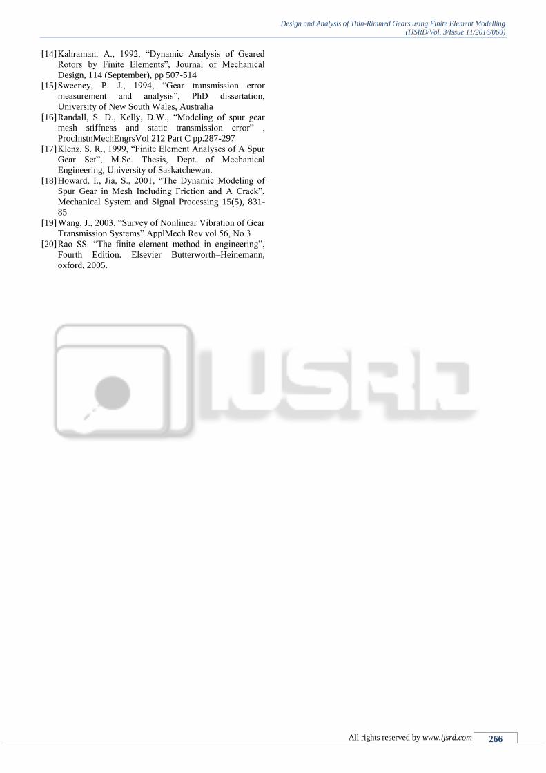
Fig. 15: Equivalent stress developed at contact
Fig. 16: Equivalent stress at the inner side of rim
Finite element modelling of the contact between
two gears was examined in detail. The finite element
method with special techniques, such as the incremental
technique of applying the external load in the input file, the
deformation of the stiffness matrix, and the introduction of
the contact element were used. It was found that initial
loading using displacements as inputs was helpful in
reducing numerical instabilities.
V. CONCLUSION
In the proposed work, the thin rimmed gear is modeled for
low cost design which is the real time application of
aircrafts. Structural, vibration, contact signals is done to
propose the various real time stress and vibration that are to
be found in the gears. These tests will produce the results in
the form of von-mises stress, deflection, deformation,
contact stress and the root cause of defects like pitting and
crack.
The contribution of the thesis work presented here
can be summarized as follows: It was shown that an FEA
model could be used to simulate contact between two bodies
accurately. Design and analysis of offset rim of thin rimmed
gear has been shown here for static, modal and contact
analysis by showing that the maximum stress are still lower
than those ultimate stress.
The element selected for the modal analysis of thin
walled spur gear is 20 node iso-parametric elements. Natural
frequencies and mode shapes of the thin-walled gears
computed by the finite element analyses are well close with
the past literature.
Mode shapes & natural frequencies get change due
to the crack propagation in the thin wall spur gear tooth
model. The frequencies are found to be low than the gear
without crack. For the first mode the rim deformations are
found and in the next mode shapes the web is bending. This
report presents the design and analysis of thin rimmed gear
using finite element analysis.
VI. FUTURE SCOPES
The following are the proposed future scopes of this work
which can be worked later on, to prove the theoretical
analysis/simulation in regards of thin rimmed gears.
1) The proposed thin gear development techniques
must be real time evaluated and decision-making
schemes will be applied to other mechanical
systems such as gearboxes and engines.
2) More investigation related to the diagnoses of
advanced thin gear faults and distributed thin gear
tooth defects will be conducted.
REFERENCES
[1] M. Botman, Vibration measurements on planetary gears
of aircraft turbine engines, Journal of Aircraft 17 (5)
(1980) 351–357.
[2] P. Timmins, Solutions to Equipment Failures, Materials
Park, OH: ASM International, 1999.
[3] D. Boulahbal, F. Golnaraghi, and F. Ismail, “Amplitude
and phase wavelet maps for the detection of cracks in
geared systems,” Mechanical Systems and Signal
Processing, 13(3), pp. 423-436, 1999.
[4] W. Wang, F. Ismail, and F. Golnaraghi, “Assessment of
gear damage monitoring techniques using vibration
measurements,” Mechanical Systems and Signal
Processing, 15(5), pp. 905-922, 2001.
[5] W. Wang, F. Golnaraghi, and F. Ismail, “Condition
monitoring of a multistage printing press,” Journal of
Sound and Vibration, 270, pp. 755-766, 2004.
[6] W. Wang, F. Golnaraghi, and F. Ismail, “Prognosis of
machine health condition using neurofuzzy systems,”
Mechanical Systems and Signal Processing, 18(4), pp.
813-831, 2004.
[7] W. Wang, F. Ismail, and F. Golnaraghi, “A neuro-fuzzy
approach for gear system monitoring,” IEEE
Transactions on Fuzzy Systems, 12(5), pp. 710-723,
2004.
[8] W. Wang, “An adaptive predictor for dynamic system
forecasting,” Mechanical Systems and Signal
Processing, 21(2), pp. 809-823, 2007.
[9] W. Wang, “An intelligent system for machinery
condition monitoring,” IEEE Transactions on Fuzzy
Systems, 16(1), pp. 110-122, 2008.
[10] Kasuba, R., “An Analytical and experimental Study of
dynamic Loads on Spur Gear Teeth”, Ph.D., University
of Illinolis
[11] kasuba R., Evans, J. W. 1981, “An Extended Model for
Determining Dynamic Loads in Spur Gearing”
[12] Mark, W. D., 1978, “Analysis of the vibratory
excitation of gear system: Basic theory”, J. Acoust. Soc.
Am., 63, 1409-1430.
[13] Mark, W. D., 1979, “Analysis of the vibratory
excitation of gear system, II: tooth error representations,
approximations, and application”, J. Scouts, Soc. Am.,
66, 1758- 1787
Design and Analysis of Thin-Rimmed Gears using Finite Element Modelling
(IJSRD/Vol. 3/Issue 11/2016/060)
All rights reserved by www.ijsrd.com 266
[14] Kahraman, A., 1992, “Dynamic Analysis of Geared
Rotors by Finite Elements”, Journal of Mechanical
Design, 114 (September), pp 507-514
[15] Sweeney, P. J., 1994, “Gear transmission error
measurement and analysis”, PhD dissertation,
University of New South Wales, Australia
[16] Randall, S. D., Kelly, D.W., “Modeling of spur gear
mesh stiffness and static transmission error” ,
ProcInstnMechEngrsVol 212 Part C pp.287-297
[17] Klenz, S. R., 1999, “Finite Element Analyses of A Spur
Gear Set”, M.Sc. Thesis, Dept. of Mechanical
Engineering, University of Saskatchewan.
[18] Howard, I., Jia, S., 2001, “The Dynamic Modeling of
Spur Gear in Mesh Including Friction and A Crack”,
Mechanical System and Signal Processing 15(5), 831-
85
[19] Wang, J., 2003, “Survey of Nonlinear Vibration of Gear
Transmission Systems” ApplMech Rev vol 56, No 3
[20] Rao SS. “The finite element method in engineering”,
Fourth Edition. Elsevier Butterworth–Heinemann,
oxford, 2005.