Embed Size (px)
Citation preview
Design and Development of KIT Student’s Experimental Rocket Shigeru Kaji, Yusuke Oshikata, Tomoki Akiyama, Yoshikazu Harada, Daisuke Sugihara, Tomoaki Shimozawa,
Shinichi Sagara, and Koichi Yonemoto Kyushu Institute of Technology
1-1 Sensui, Tobata, Kitakyushu, Fukuoka 804-8550, Japan (Phone/Fax : +81-93(884)3179 ;E-mail: [email protected])
Abstract: Small experimental rockets have been developed by a student group of Kyushu Institute of Technology for the rocket launch campaign held at La Courtine military camp in France since 2006, which is conducted by French Planète Sciences and controlled by CNES (Centre National D’Etudes Spatiales). This paper introduces the newest design of rocket. The main mission is recovery guidance to an aiming point by controlling rolling attitude using two ailerons during ascent phase and then deploying a parafoil at an apogee of trajectory. The rocket has a body length of 2.1m, and weighs 14.7kg and can reach to an altitude of 640m by a solid rocket motor provided by CNES. The final ground system tests was conducted to check the NGC system and to evaluate the roll control performance in a low speed wind tunnel facility. Keywords: Experimental rocket, Navigation, guidance and control, Roll control by aileron
1. INTRODUCTION Under the control of CNES (Centre National D’Etudes
Spatiales), the French non-profit organization Planète Sciences has been conducting for amateur clubs, such as university students and young industry engineers as well, a yearly experimental rocket launch campaign called “La Campagne Nationale de Lancement” since 1962 [1].
The purpose of the rocket launch campaign is not only to make their dream come true but also to teach them how the actual development is processed. CNES and Planète Sciences provide various design documents in terms of safety regulation [2], specification of solid rocket motors [3] and telemetry system interface [4], consult technical problems as required, and review designs and make advices from the safety point of view before getting into manufacturing. The final review is the ground tests that are conducted on the site of launch campaign in order to give launch approval.
The ground tests consist of four technical fields. The first field is called “Méchanique”, which includes geometry, mass and center of gravity measurements, stability calculation, trajectory simulation, static load test, body stiffness test, and fin load test. The second field is called “Expérience” to check calibration coefficients of all sensors, readiness of telemetry transmission and review onboard software computers. The third field is called “Recupération” to check recovery system. If the recovery system is controlled by onboard computer, one must demonstrate its complete operation ten times. The final field is called “Vol Simulé” to simulate all of the onsite operation. One starts with pre-flight preparation outside the critical zone, sets up the rocket to launch pad, then turns power switch on, runs onboard computer, simulates rocket motor ignition by pulling out plug jack to start onboard timer. This simulation test continues until the onboard computer demonstrates all the sequence of events successfully.
In addition to the technical process toward rocket launch, the amateur clubs learn a lot of team work and project management concerning schedule and budged. Sometime they are faced to technical difficulties and have to negotiate with CNES professional engineers how to come over the problems. Collaboration with other clubs often bears fruitful results as much as one expects by exchanging know-how each other. These kinds of practical activity are important and necessary aspects for actual development [5].
A student group of Kyushu Institute of Technology has been participated in the French experimental rocket launch campaign since 2006 [6-7]. This paper focuses on the technical aspect to introduce the newest design and development of the rocket was launched 2007.
2. ROCKET DIMENSIONS AND MISSION PROFILE
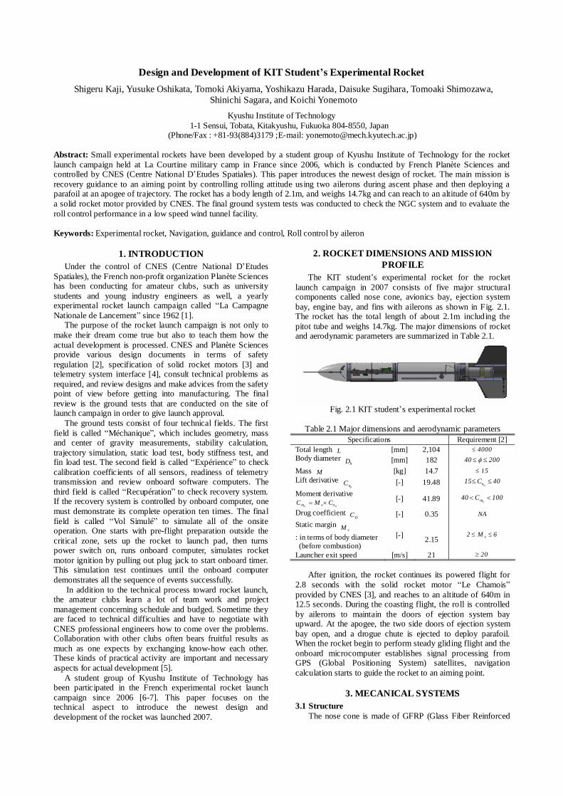
The KIT student’s experimental rocket for the rocket launch campaign in 2007 consists of five major structural components called nose cone, avionics bay, ejection system bay, engine bay, and fins with ailerons as shown in Fig. 2.1. The rocket has the total length of about 2.1m including the pitot tube and weighs 14.7kg. The major dimensions of rocket and aerodynamic parameters are summarized in Table 2.1.
Fig. 2.1 KIT student’s experimental rocket
Table 2.1 Major dimensions and aerodynamic parameters
Specifications Requirement [2] Total length L [mm] 2,104 4000 Body diameter
bD [mm] 182 20040
Mass M [kg] 14.7 15 Lift derivative
nC [-] 19.48 40C15 n
Moment derivative nsm CMC [-] 41.89 100C40 m
Drug coefficient DC [-] 0.35 NA
Static margin sM
: in terms of body diameter (before combustion)
[-] 2.15
6M2 s
Launcher exit speed [m/s] 21 20
After ignition, the rocket continues its powered flight for
2.8 seconds with the solid rocket motor “Le Chamois” provided by CNES [3], and reaches to an altitude of 640m in 12.5 seconds. During the coasting flight, the roll is controlled by ailerons to maintain the doors of ejection system bay upward. At the apogee, the two side doors of ejection system bay open, and a drogue chute is ejected to deploy parafoil. When the rocket begin to perform steady gliding flight and the onboard microcomputer establishes signal processing from GPS (Global Positioning System) satellites, navigation calculation starts to guide the rocket to an aiming point.
3. MECANICAL SYSTEMS
3.1 Structure The nose cone is made of GFRP (Glass Fiber Reinforced
Plastic). The rocket body is a monocoque structure made of four CFRP (Carbon Fiber Reinforced Plastic) tubes that are reinforced by aluminum alloy flanges and stringers. These body tubes are fastened at each flange by bolts. The four fins are made of CFRP plate to realize static stability. The two fins in the opposite side have ailerons, respectively.
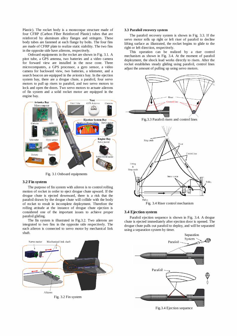
Onboard equipments in the rocket are shown in Fig. 3.1. A pitot tube, a GPS antenna, two batteries and a video camera for forward view are installed in the nose cone. Three microcomputers, a GPS processor, a gyro sensor, a video camera for backward view, two batteries, a telemeter, and a search beacon are equipped in the avionics bay. In the ejection system bay, there are a drogue chute, a parafoil, four servo motors to pull up risers to parafoil, and two servo motors to lock and open the doors. Two servo motors to actuate ailerons of fin system and a solid rocket motor are equipped in the engine bay.
3.2 Fin system The purpose of fin system with aileron is to control rolling
motion of rocket in order to eject drogue chute upward. If the drogue chute is ejected downward, there is a risk that the parafoil drawn by the drogue chute will collide with the body of rocket to result in incomplete deployment. Therefore the rolling attitude at the instance of drogue chute ejection is considered one of the important issues to achieve proper parafoil gliding.
The fin system is illustrated in Fig.3.2. Two ailerons are integrated to two fins in the opposite side respectively. The each aileron is connected to servo motor by mechanical link shaft.
Fig. 3.2 Fin system
3.3 Parafoil recovery system The parafoil recovery system is shown in Fig. 3.3. If the
servo motor rolls up right or left riser of parafoil to decline lifting surface as illustrated, the rocket begins to glide to the right or left direction, respectively.
This operation can be realized by a riser control mechanism as shown in Fig. 3.4. At the moment of parafoil deployment, the shock load works directly to risers. After the rocket establishes steady gliding using parafoil, control lines adjust the amount of pulling up using servo motors.
Fig.3.3 Parafoil risers and control lines
Fig. 3.4 Riser control mechanism
3.4 Ejection system
Parafoil ejection sequence is shown in Fig. 3.4. A drogue chute is ejected immediately after ejection door is opened. The drogue chute pulls out parafoil to deploy, and will be separated using a separation system by timer.
Fig. 3.1 Onboard equipments
Fig.3.4 Ejection sequence
The ejection system bay is shown in Fig. 3.5. Two ejection doors are attached by spring hinges on each side of body. The parafoil is folded up and stored in the container made of cloth. Since the container cloth is stuck to inside of the bay by Velcro, it can be detached and attached easily.
Fig. 3.5 Ejection system bay
The lock mechanism of ejection door is shown in Fig. 3.6.
The two doors are locked by overlapping two clasps together. When a servo motor rotates a hook to release the clasps, the ejection doors are opened.
Fig. 3.6 Lock mechanism of ejection door
The drogue chute ejection system is shown in Fig. 3.7.
There is a sector board to lock the drogue chute ejection box. The servo motor rotates the sector board to release the drogue chute ejection box immediately after the ejection doors open.
Fig. 3.7 Drogue chute ejection system
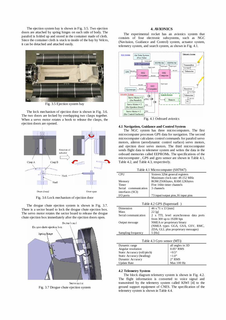
4. AVIONICS The experimental rocket has an avionics system that
consists of four electronic subsystems, such as NGC (Navitaion, Guidance and Control) system, actuator system, telemetry system, and search system, as shown in Fig. 4.1.
Fig. 4.1 Onboard avionics
4.1 Navigation, Guidance and Control System
The NGC system has three microcomputers. The first microcomputer processes GPS data for navigation. The second microcomputer calculates control commands for parafoil servo motors, aileron (aerodynamic control surface) servo motors, and ejection door servo motors. The third microcomputer sends flight data to telemeter system and writes the data in the onboard memories called EEPROMs. The specifications of the microcomputer , GPS and gyro sensor are shown in Table 4.1, Table 4.2, and Table 4.3, respectively.
Table 4.1 Microcomputer (SH7047)
CPU Sixteen 32bit general registers Maximum clock rate: 49.152 MHz
Memory ROM:256Kbytes, RAM:12Kbytes Timer Five 16bit timer channels Serial communication interfaces (SCI)
3 channels
I/O ports 73 input/output pins,16 input pins
Table 4.2 GPS (SuperstarⅡ) Dimension 46 x 71 x 13 [mm] Mass 22 [g] Serial communication 2 x TTL level asynchronous data ports
from 300 up to 19200 bps Output message NMEA or proprietary binary
(NMEA types GGA, GSA, GSV, RMC, ZDA, GLL plus proprietary messages)
Sampling frequency 5 [Hz]
Table 4.3 Gyro sensor (MTi) Dynamic range all angles in 3D Angular resolution 0.05° RMS Static Accuracy (roll/pitch) <0.5° Static Accuracy (heading) <1.0° Dynamic Accuracy 2° RMS Update Rate Max 100 Hz 4.2 Telemetry System
The block diagram telemetry system is shown in Fig. 4.2. The flight information is converted to voice signal and transmitted by the telemetry system called KIWI [4] to the ground support equipment of CNES. The specification of the telemetry system is shown in Table 4.4.
Gyro Sensor
Pulse motors
Fig. 5.1 Gyro simulator
Fig.4.2 Onboard and ground telemetry system
Table 4.4 Telemetry system
Transmission frequency 1, 2 137.95, 138.5 [MHz] Serial communication 4800 [bps] FSK modulator chip XR2206 FSK demodulators chip XR2211 Low state, high state 9 [KHz], 15 [KHz] 4.3 Power supply system
The power supply system has four batteries of 7.4 Volts DC as shown in Fig. 4.3. The first battery supplies 5V DC through the regulator to the NGS system. The second and the third batteries supply 12V DC through the DC-DC converter to the telemetry system and the search system, respectively. The forth battery supplies 7.4V DC directly to the servo motors used for controlling parafoil risers and regulated 6V DC to the servo motors to open the ejection doors and to control ailerons of fin system.
Fig. 4.3 Power supply system
5. GROUND TESTS The basic ground tests conducted prior to the final review tests onsite are introduced. 5.1 Gyro sensor test
The onboard gyro sensor was tested and calibrated using a simple gyro simulator composed of three commercial-off-the-shelf pulse motors as shown in Fig.5.1, which has a minimum resolution of 0.36 degrees/pulse. 5.2 Wind tunnel test
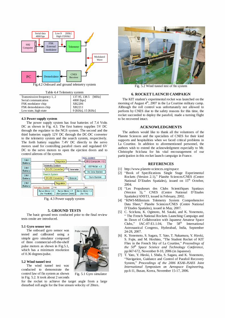
The wind tunnel test was conducted to demonstrate the control law of fin system as shown in Fig. 5.2. It took about 2 seconds for the rocket to achieve the target angle from a large disturbed roll angle for the free stream velocity of 20m/s.
Fig. 5.2 Wind tunnel test of fin system
6. ROCKET LAUNCH CAMPAIGN
The KIT student’s experimental rocket was launched on the morning of August 4th, 2007 in the La Courtine military camp. Although the roll control was unfortunately not allowed to perform by CNES due to the safety reasons for this time, the rocket succeeded to deploy the parafoil, made a turning flight to be recovered intact.
ACKNOWLEDGMENTS
The authors would like to thank all the volunteers of the Planete Sciences and the specialists of CNES for their kind supports and hospitalities when we faced critical problems in La Courtine. In addition to aforementioned personnel, the authors wish to extend the acknowledgment especially to Mr. Christophe Scicluna for his vital encouragement of our participation in this rocket launch campaign in France.
REFERENCES
[1] http://www.planete-sciences.org/espace [2] “Book of Specifications Single Stage Experimental
Rockets (Version 2.1),” Planéte Sciences/CNES (Centre National D’Etudes Spatiales), issued on 15th October, 2004.
[3] “Les Propulseurs des Clubs Scientifiques Spatiaux (Version 5), ” CNES (Centre National D’Etudes Spatiales)/ANSTJ, issued in February, 2002.
[4] “KIWI-Millenium Telemetry System Comprehensive Data Sheet,” Planéte Sciences/CNES (Centre National D’Etudes Spatiales), issued in May, 2007.
[5] C. Scicluna, K. Ogimoto, M. Sasaki, and K. Yonemoto, “ The French National Rockets Launching Campaign and its Dawn of Collaboration with Japanese Amateur Space Clubs,” IAC-07-E1.1.04, The 58th International Astronautical Congress, Hyderabad, India, September 24-28, 2007.
[6] K. Yonemoto, S. Sagara, T. Yato, T. Nakamura, Y. Hiroki, S. Fujie, and M. Hoshino, “The Student Rocket of KIT Flies in the French Sky of La Courtine,” Proceedings of the 50th Space Science and Technology Conference, pp.667-672, November 8-10, 2006 (in Japanese).
[7] T. Yato, Y. Hiroki, I. Shida, S. Sagara, and K. Yonemoto, “Navigation, Guidance and Control of Parafoil Recovery System,” Proceedings of the 2006 KSAS-JSASS Joint International Symposium on Aerospace Engineering, pp.6-11, Busan, Korea, November 15-17, 2006.
Low:9 [KHz] High:15[KHz]
Serial data 4800 bps
Telemeter SH2
Computer
FSK External
modulator
CNES Receiver
Demodulator
PC
Modulated Wave