Embed Size (px)
Citation preview
Design, Manufacture and UT Results on Blocks with Fatigue Cracks from L‐0 Blades
Peter Ciorau – Ontario Power Generation‐ Pickering ‐ Canada [email protected] Smith – CADWIRE ‐ Markham‐ Canada [email protected] Daks – CADWIRE ‐ Markham – Canada [email protected] Abstract: The paper presents technical aspects of design and manufacture specific blocks with
fatigue cracks from L‐0 Blades – retired from service. The scope of this exercise was a multitude of projects running within OPG – IM&CS Division:
• Inspection Qualification for CANDU Piping (effect of root, suck back, counterbore in crack detection; detection and sizing capability for large thickness > 40 mm)
• PAUT crack sizing – outer surface techniques • PAUT crack sizing – specular large thickness > 120 mm – Nanticoke Boiler Feed
Water Pump (Emergency Stop Valve and Governor Valve) and Main Steam Valves • PAUT crack sizing – L‐0 steeple grooves (hook 2‐5) – Darlington Nuclear GS
The challenge to optimize the block dimensions by preserving the crack profile and height was overcome by using an advanced 3‐D drafting package with capability to incorporate and run actual data PAUT files in the 3‐D specimen. The paper presents 3 categories of blocks [ bars with weld geometric defects, large thickness bars and pipe coupons and L‐0 steeple test pieces‐all with fatigue cracks],and PAUT results on multiple scanning combinations. This exercise came as a great success for Technical Justification‐Inspection Qualification, for Capability Demonstration‐L‐waves large thickness and for technician training for in‐situ PAUT inspection at Darlington Station in Feb.2010. Based on experimental data, PAUT parameters were optimized. Cracks as low as 5‐mm are reliable sized at depth of 210 mm. Cracks as low as 3‐mm are reliable sized at depth of 120 mm. Both conventional and PAUT are capable to detect and size fatigue cracks with h > 3 mm at depth of 40+ mm.
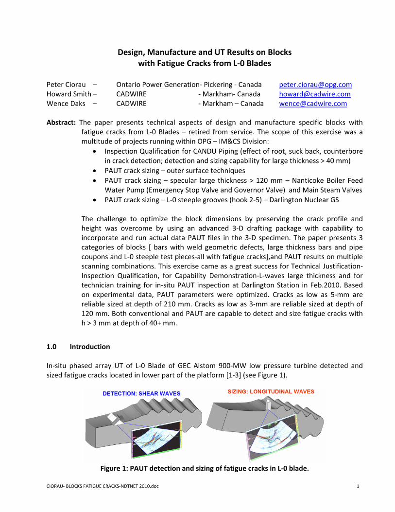
1.0 Introduction In‐situ phased array UT of L‐0 Blade of GEC Alstom 900‐MW low pressure turbine detected and sized fatigue cracks located in lower part of the platform [1‐3] (see Figure 1).
Figure 1: PAUT detection and sizing of fatigue cracks in L‐0 blade.
CIORAU‐ BLOCKS FATIGUE CRACKS‐NDTNET 2010.doc 1
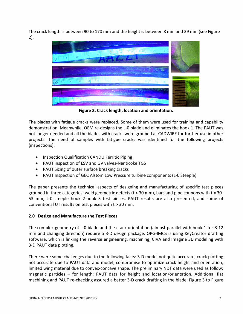
The crack length is between 90 to 170 mm and the height is between 8 mm and 29 mm (see Figure 2).
Figure 2: Crack length, location and orientation.
The blades with fatigue cracks were replaced. Some of them were used for training and capability demonstration. Meanwhile, OEM re‐designs the L‐0 blade and eliminates the hook 1. The PAUT was not longer needed and all the blades with cracks were grouped at CADWIRE for further use in other projects. The need of samples with fatigue cracks was identified for the following projects (inspections):
• Inspection Qualification CANDU Ferritic Piping • PAUT inspection of ESV and GV valves‐Nanticoke TGS • PAUT Sizing of outer surface breaking cracks • PAUT Inspection of GEC Alstom Low Pressure turbine components (L‐0 Steeple)
The paper presents the technical aspects of designing and manufacturing of specific test pieces grouped in three categories: weld geometric defects (t < 30 mm), bars and pipe coupons with t = 30‐53 mm, L‐0 steeple hook 2‐hook 5 test pieces. PAUT results are also presented, and some of conventional UT results on test pieces with t > 30 mm. 2.0 Design and Manufacture the Test Pieces The complex geometry of L‐0 blade and the crack orientation (almost parallel with hook 1 for 8‐12 mm and changing direction) require a 3‐D design package. OPG‐IMCS is using KeyCreator drafting software, which is linking the reverse engineering, machining, CIVA and Imagine 3D modeling with 3‐D PAUT data plotting. There were some challenges due to the following facts: 3‐D model not quite accurate, crack plotting not accurate due to PAUT data and model, compromise to optimize crack height and orientation, limited wing material due to convex‐concave shape. The preliminary NDT data were used as follow: magnetic particles – for length; PAUT data for height and location/orientation. Additional flat machining and PAUT re‐checking assured a better 3‐D crack drafting in the blade. Figure 3 to Figure
CIORAU‐ BLOCKS FATIGUE CRACKS‐NDTNET 2010.doc 2
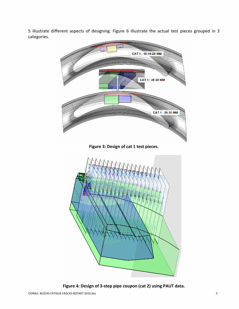
5 illustrate different aspects of designing. Figure 6 illustrate the actual test pieces grouped in 3 categories.
Figure 3: Design of cat 1 test pieces.
Figure 4: Design of 3‐step pipe coupon (cat 2) using PAUT data.
CIORAU‐ BLOCKS FATIGUE CRACKS‐NDTNET 2010.doc 3
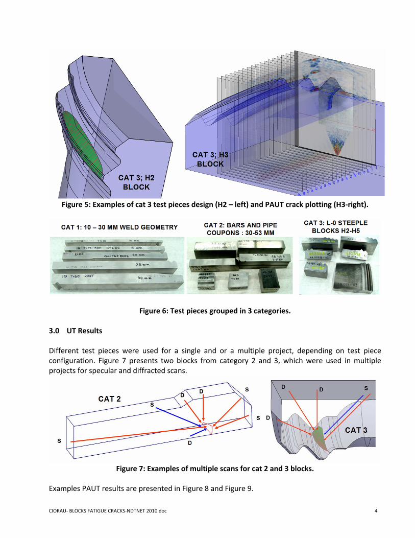
Figure 5: Examples of cat 3 test pieces design (H2 – left) and PAUT crack plotting (H3‐right).
Figure 6: Test pieces grouped in 3 categories.
3.0 UT Results Different test pieces were used for a single and or a multiple project, depending on test piece configuration. Figure 7 presents two blocks from category 2 and 3, which were used in multiple projects for specular and diffracted scans.
Figure 7: Examples of multiple scans for cat 2 and 3 blocks.
Examples PAUT results are presented in Figure 8 and Figure 9. CIORAU‐ BLOCKS FATIGUE CRACKS‐NDTNET 2010.doc 4
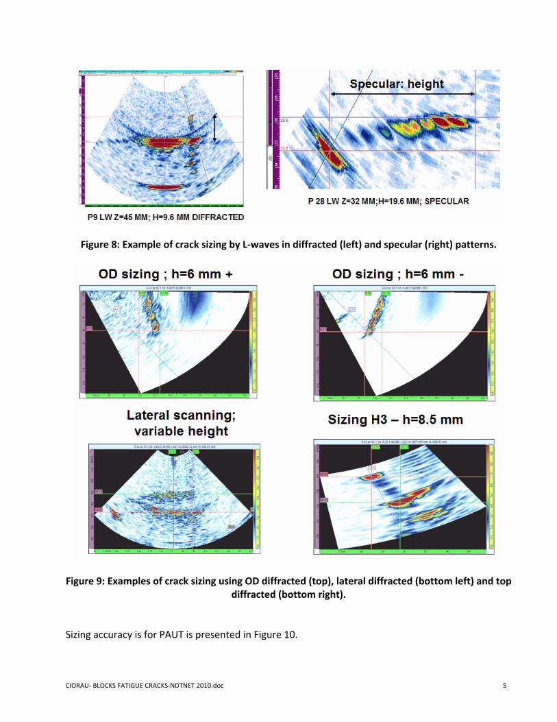
Figure 8: Example of crack sizing by L‐waves in diffracted (left) and specular (right) patterns.
Figure 9: Examples of crack sizing using OD diffracted (top), lateral diffracted (bottom left) and top diffracted (bottom right).
Sizing accuracy is for PAUT is presented in Figure 10.
CIORAU‐ BLOCKS FATIGUE CRACKS‐NDTNET 2010.doc 5
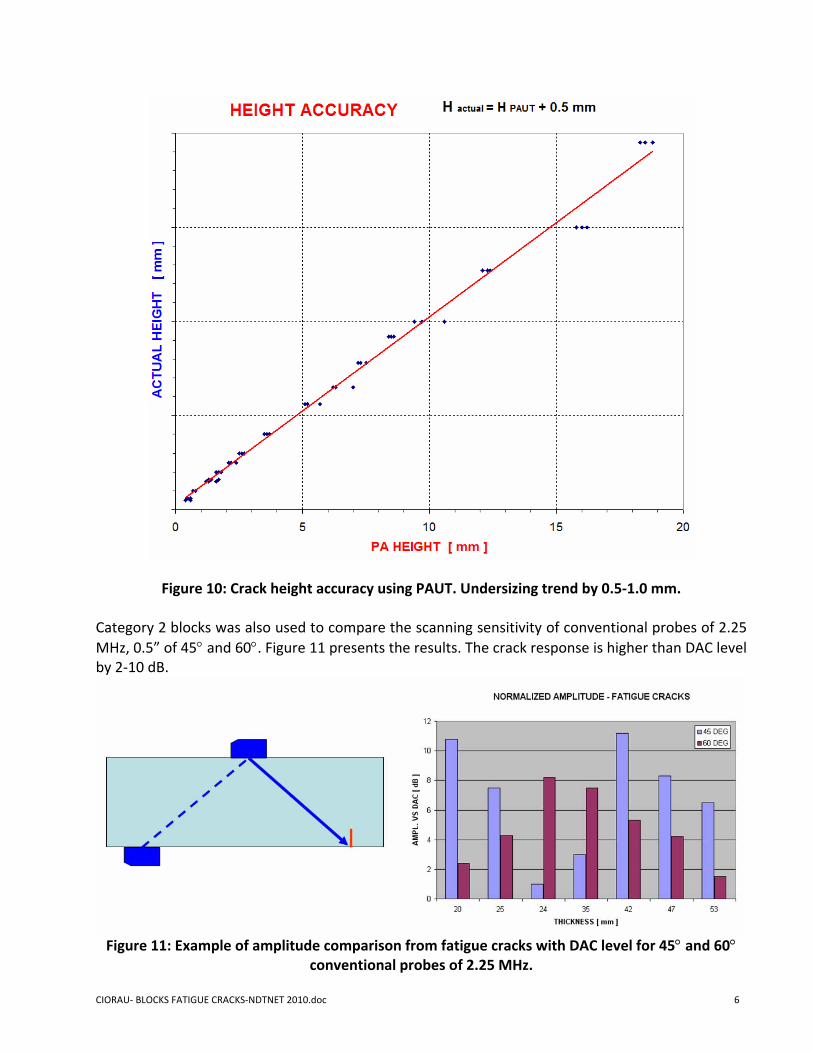
Figure 10: Crack height accuracy using PAUT. Undersizing trend by 0.5‐1.0 mm.
Category 2 blocks was also used to compare the scanning sensitivity of conventional probes of 2.25 MHz, 0.5” of 45° and 60°. Figure 11 presents the results. The crack response is higher than DAC level by 2‐10 dB.
Figure 11: Example of amplitude comparison from fatigue cracks with DAC level for 45° and 60°
conventional probes of 2.25 MHz.
CIORAU‐ BLOCKS FATIGUE CRACKS‐NDTNET 2010.doc 6
4.0 Conclusions The design and manufacturing of test pieces from L‐0 blades with fatigue cracks was a real challenge, but came as a success. The results were used to assess the sizing accuracy and detection sensitivity. Category 3 blocks was used for technician training for outage inspection. PAUT is under sizing by 0.5 – 1.0 mm the cracks. 5.0 References 1. Ciorau, P., L. Pullia, W. Daks, H. Smith: “3‐D Data Plotting‐ a Useful Tool for PAUT “– ndt.net
– vol. 13, no.7 (Jul 2008), CINDE Journal May/June 2009 2. Ciorau, P., W.Daks. H. Smith: “Reverse Engineering of 3‐D Crack‐like EDM Notches and
Phased Array Ultrasonic Results on Low‐pressure Turbine Components Mock‐ups.” ‐ 7‐th CANDU Maintenance Conf.‐Toronto‐Nov.22‐2005 (also at 4‐th PA seminar‐EPRI‐Miami –Dec 2005, ndt.net‐vol.9 (Oct 2005)
3. Ciorau, P., W. Daks, C. Kovacshazy, D. Mair: “ Advanced 3D Tools Used in Reverse Engineering and Ray Tracing Simulation of Phased Array Inspection of Turbine Components with Complex Geometry” – 8th Eur. Conf NDT‐Barcelona, June 2002, ndt.net –vol. 8 (Oct. 2004)
Acknowledgement: The authors wish to thank OPG – IM&CS Management for granting the publication of this paper.
CIORAU‐ BLOCKS FATIGUE CRACKS‐NDTNET 2010.doc 7