Embed Size (px)
Citation preview
Czech Technical University in Prague
Faculty of Electrical Engineering
Bachelor thesis
Design of Communication Subsystem for Unmanned
Aerial Vehicle
Vojtěch Kubica
Thesis supervisor: Ing. Martin Selecký
Major: Cybernetics and robotics
Specialization: Systems and control
May 2015

I
Prohlášení
Prohlašuji, že jsem předloženou práci vypracoval samostatně a že jsem uvedl veškeré
použité informační zdroje v souladu s Metodickým pokynem o dodržování etických
principů při přípravě vysokoškolských závěrečných prací.
V Praze, dne ………………………. …………………………………….
Podpis

II

III
Acknowledgements
I would like to thank all the people, who helped me in any way in this bachelor thesis.
Especially, I would like to express my gratitude to my supervisor, Ing. Martin Selecký,
for his excellent guidance, caring and patience.

IV
V
Abstrakt
Cílem této studie je prozkoumat vlastnosti a použitelnost některých technologií
používaných v komunikačních systémech bezpilotních letadel. Stanovení míry použitelnosti těchto
technologií je podpořeno daty z uskutečněných experimentů.
Práce nejdříve podává přehled komunikačních řešení, které jsou nasazovány v leteckých
systémech. Následuje přiblížení problematiky šíření radiového signálu a způsobu komunikace
v mobilních bezdrátových sítích. Testovány jsou mobilní telekomunikace a radiofrekvenční
modemy. Porovnáním výsledků zkoumání těchto technologií vyplynou rozdíly, které vedou
k patřičným doporučením v oblasti jejich nasazení.
Klíčová slova: Bezpilotní letadlo, bezdrátová komunikace, mobilní síť, radiofrekvenční
signál, šíření signálu.
Abstract
The goal of this study is to investigate the level of suitability of various wireless communication
technologies for use in unmanned aerial systems. The determination of suitability is supported by
data from real measurements.
The thesis firstly gives an overview of communication solutions that are usable for aerial platforms
and then looks closely to the problematics of radio frequency signal propagation, and to
communication in wireless mobile networks. The mobile telecommunications and RF modem
communication are tested and compared to each other giving differences and recommendations for
particular areas of use are suggested.
Keywords: Unmanned aerial vehicle, wireless communication, mobile network, radio-
frequency signal, signal distribution.

VI
Czech Technical University in Prague Faculty of Electrical Engineering
Department of Control Engineering
BACHELOR PROJECT ASSIGNMENT
Student: Vojtěch Kubica
Study programme: Cybernetics and Robotics Specialisation: Systems and Control
Title of Bachelor Project: Design of Communication Subsystem for Unmanned Aerial Vehicle
Guidelines:
1. Study the problematics of radio frequency (RF) signal propagation. 2. Study the problematics of communication in wireless mobile networks. 3. Investigate existing communication devices suitable for mobile aerial platforms. 4. Integrate selected communication unit with UAV's on-board devices. 5. Design and carry out experiments for measurement of characteristics of selected communication units.
Bibliography/Sources:
[1] Sarkar, Subir Kumar, T. G. Basavaraju, and C. Puttamadappa. Ad hoc mobile wireless networks: principles, protocols and applications. CRC Press, 2007. [2] P. Santi: Topology Control in Wirelss Ad Hoc and Sensor Networks. Wiley, 2005
Bachelor Project Supervisor: Ing. Martin Selecký
Valid until summer semester 2015/2016
L.S.
prof. Ing. Michael Šebek, DrSc. Head of Department
prof. Ing. Pavel Ripka, CSc. Dean
Prague, January 30, 2015

IX
Table of Contents
1 Introduction .................................................................................................................. 1
1.1 Unmanned Aerial Vehicle ................................................................................................ 1
1.2 Motivation ........................................................................................................................ 1
1.3 Contribution ...................................................................................................................... 2
1.4 Thesis organization ........................................................................................................... 2
2 Communication for mobile aerial platforms .................................................................. 2
2.1 Satellites ........................................................................................................................... 3
2.2 Radio frequency modems ................................................................................................. 4
2.3 Free-Space Optical ........................................................................................................... 4
2.4 Mobile telecommunications ............................................................................................. 5
3 Radio Frequency Communication ................................................................................. 6
3.1 Radio Frequency Signal Propagation ............................................................................... 6
3.1.1 Scattering .................................................................................................................. 7
3.1.2 Diffraction ................................................................................................................ 8
3.1.3 Refraction ................................................................................................................. 8
3.1.4 Reflection ................................................................................................................. 9
3.1.5 Absorption .............................................................................................................. 10
3.1.6 Interference ............................................................................................................. 10
3.1.7 Free space propagation model ................................................................................ 11
3.2 Parameters of signal quality ........................................................................................... 12
3.2.1 Shannon–Hartley theorem ...................................................................................... 12
3.3 Wireless mobile networks .............................................................................................. 13
3.3.1 Signal availability problem ..................................................................................... 13
3.3.2 Signal availability solutions ................................................................................... 14
3.3.3 Routing Protocol ..................................................................................................... 15
3.4 Frequency bands ............................................................................................................. 16
3.4.1 Allowed frequencies ............................................................................................... 16
4 Implementation ........................................................................................................... 16
4.1 Computational unit ......................................................................................................... 17
4.2 Communication unit ....................................................................................................... 18
4.2.1 XBee - PRO ............................................................................................................ 18
4.2.2 Microhard nVIP2400 .............................................................................................. 19
4.2.3 Mobile network ...................................................................................................... 19
X
4.3 UAV’s positioning system ............................................................................................. 20
4.4 Hardware placement on UAV ........................................................................................ 21
4.4.1 RF-modem configuration ....................................................................................... 21
4.4.2 Mobile-network configuration ............................................................................... 22
4.5 Experimentation software .............................................................................................. 22
4.5.1 Mobile network analysis software ......................................................................... 22
4.5.2 RF measures software and data processing ............................................................ 23
5 Experiments ................................................................................................................ 24
5.1 Physical quantities ......................................................................................................... 24
5.1.1 Antenna rotation calculation .................................................................................. 24
5.2 Scenarios ........................................................................................................................ 25
5.2.1 Flyby ...................................................................................................................... 25
5.2.2 Circling .................................................................................................................. 26
5.2.3 Mobile telecommunication-testing scenarios ......................................................... 27
5.3 Experiment settings ........................................................................................................ 27
5.4 Results and comparison ................................................................................................. 28
5.4.1 Mobile telecommunications ................................................................................... 28
5.4.2 RF modems ............................................................................................................ 31
5.5 Comparison .................................................................................................................... 33
6 Conclusions ................................................................................................................. 34
7 Bibliography ................................................................................................................ 37
A Content of the enclosed CD .............................................................................................. I
XI
List of Figures
Figure 2-1: Satellite communication (borrowed from http://privat.bahnhof.se/) ............................. 4
Figure 2-2: Cellular network (borrowed from http://en.wikipedia.org/wiki/Cellular_network) ...... 5
Figure 2-3: Coverage of mobile telecommunications (source: http://opensignal.com/) .................. 6
Figure 3-1: Fresnel zone at point P (borrowed from http://en.wikipedia.org/wiki/Fresnel_zone) ... 7
Figure 3-2: A Feynman diagram of scattering between two electrons by emission of a virtual
photon. (borrowed from http://en.wikipedia.org/wiki/Scattering) ................................................... 8
Figure 3-3: Diffraction (borrowed from http://physics.taskermilward.org.uk/) ............................... 8
Figure 3-4: Snell's law (borrowed from http://en.wikipedia.org/wiki/Refraction) ........................... 9
Figure 3-5: Diagram of specular reflection (borrowed from
http://en.wikipedia.org/wiki/Reflection_(physics)) ........................................................................ 10
Figure 3-6: The hidden node problem ............................................................................................ 14
Figure 3-7: The exposed node problem .......................................................................................... 14
Figure 4-1: Air to ground communication configuration – RF modems ........................................ 17
Figure 4-2: Colibri T30 module (left), Iris Carrier Boat (right) ..................................................... 17
Figure 4-3: XBee-PRO module ...................................................................................................... 18
Figure 4-4: Microhard nVIP2400 ................................................................................................... 19
Figure 4-5: Rubber Ducky Antenna radiation pattern .................................................................... 19
Figure 4-6: BTS radiation pattern (borrowed from http://www.raymaps.com/) ............................ 20
Figure 4-7: Mobile device BenQ F5 provides 4G/LTE .................................................................. 20
Figure 4-8: Autopilot system APM 2.6 + GPS (borrowed from http://dev.ardupilot.com/) .......... 21
Figure 4-9: Motor effects and antenna placement .......................................................................... 21
Figure 4-10: UAV for RF modems communication ....................................................................... 22
Figure 4-11: UAV for mobile telecommunications investigation .................................................. 22
Figure 4-12: Preview of used applications ..................................................................................... 23
Figure 5-1: aircraft principal axes .................................................................................................. 24
Figure 5-2: Antenna rotation calculation scheme ........................................................................... 25
Figure 5-3: Flyby flight plan and radiation pattern coverage ......................................................... 25
Figure 5-4: Circling flight plan and radiation pattern coverage ..................................................... 26
Figure 5-5: Distant circling scenario .............................................................................................. 26
Figure 5-6: Place for mobile telecommunications investigation .................................................... 27
Figure 5-7: Data-rate speeds at ground level .................................................................................. 28
Figure 5-8: Flight information - download ..................................................................................... 29
Figure 5-9: Flight information – upload ......................................................................................... 30
Figure 5-10: Flight information – latency investigation ................................................................. 31
Figure 5-11: RSSI vs. Distance to the ground station (RF) ............................................................ 32
Figure 5-12: Signal distribution model with and without motor running ....................................... 32
Figure 5-13: xBee PRO signal distribution model (borrowed from [3]) ........................................ 33
Figure 5-14: Microhard nVIP2400 signal distribution model ........................................................ 34
Figure 5-15: UAV used by Tomáš Meiser for xBee experiments (borrowed from [3]) ................. 34

XII
CHAPTER 1. INTRODUCTION
1
1 Introduction
1.1 Unmanned Aerial Vehicle
An unmanned aerial vehicle (UAV) is an aircraft without a human pilot aboard. UAVs can be
either piloted remotely as a remotely piloted aircraft system (RPAS) or they can fly autonomously
based on pre-programmed flight plans or being controlled by more complex control algorithms.
Now there are highly autonomous UAVs, which require minimum of human intervention or
supervision of a human and in the near future, we can expect fully autonomous UAVs capable of
own localization and high level mission planning capabilities that would be able to autonomously
take-off, execute various operator scheduled missions and return safely to the base.
Area of use of autonomous UAVs grows with rising technology capabilities of systems, including
artificial intelligence techniques in planning and sensing domains, as well as with improving
communication technologies. Current UAVs are capable of staying in the air for up to tens of
hours, where can they operate autonomously or controlled remotely even conditions that a human
pilot could not manage.
They are usually deployed for military and special operation applications, but also used in a
growing number of civilian applications, such as policing and firefighting, and nonmilitary
security work, such as inspection of power or pipelines. They are used for ground scanning or
monitoring ground areas or moving targets. UAVs are preferred for missions that are too "dull,
dirty or dangerous", especially in environments where the pilot might be significantly at risk of
losing his life utilizing its greatest advantage of no human on board.
1.2 Motivation
Department of Computer Science at FEE, CTU develop a system for command & control of
autonomous UAVs to be used in tactical missions like exploration of unknown areas, monitoring
of moving ground targets, patrolling around critical infrastructures etc. During the missions,
individual UAVs exchange positions and flight plans in order to cooperate (divide the objective
to subtasks and allocation of the subtask among the team members) and also to reveal a possible
future collisions in order to avoid them - for example by application of evasive maneuvers.
To realize these exchanges the unmanned vehicles need an independent reliable communication
subsystem with small delays and large bandwidth capable to transfer data to distances from
hundreds of meters to few kilometers depending on flight speeds, number of communicating units
and size of transmitted data. It is also necessary that the communication unit is small and light-
weight enough so that it can be carried by small aerial vehicles.
This communication system has to take several problems specific for the field of use into
consideration - the movement of communication nodes, their temporary unavailability or
CHAPTER 2. COMMUNICATION FOR MOBILE AERIAL PLATFORMS
2
interference with other on-board devices that can generate a lot of interfering noise (e.g. the
motor).
1.3 Contribution
This thesis investigates the problematics of communication in wireless mobile networks, find
possibilities of available technologies and off-the-shelf communication devices together with
their characteristics, and derive some conclusions about advantages and disadvantages of those
systems and their suitability for existing autonomous multi-UAV system.
We will select the most suitable technology and choose some of the existing off-the-shelf
communication devices and deploy them on a real UAV. Further, we will perform experiments
to verify the theoretical premises in the field, and to estimate the characteristics of tested systems
and their suitability.
1.4 Thesis organization
The thesis is divided into two parts, theoretical and experimental one. The theoretical part begins
with chapter 2, which describes the problems of radio frequency signal propagation. The
theoretical part continues with chapter 3 that focuses on the problematics of communication in
wireless mobile networks. The thesis continues with chapter 4, Implementation, which is kind of
transition between theoretical and experimental part. Firstly, existing devices suitable for mobile
aerial platforms are investigated and description of the devices used for experiments follows.
Right after description of hardware platform the chapter focuses on the software implementation
needed to run experiments. Then follows chapter 5, which is an overview of experiments that
examine the chosen communication interfaces. It describes the suggested scenarios and their
realization and presents the measured results. Finally, chapter 6 concludes this thesis, gives an
overview of tested devices and suggests possible future work.
2 Communication for mobile aerial platforms
Communication plays crucial role in operation of UAVs. An example of an importance of
communication capability are the requirements of not-fully autonomous aerial vehicles that need
to be controlled remotely, known as RPAS - remotely piloted aircraft systems. In general, the
connection for controlling the aircraft has to be reliable and stable, but it may differ when we
consider higher level of autonomy, where the control signals can only contain for example mission
objectives or waypoints. Communication channel for controlling the aircraft can be either simplex
or duplex channel where the receiver is the UAV. Simplex channel is used when there is no need
of getting additional data except e.g. the visual contact. The other is used when there is a
CHAPTER 2. COMMUNICATION FOR MOBILE AERIAL PLATFORMS
3
requirement of transmission of additional data, which can refer to the telemetry or any other flight
information or data collected by a UAV (photos, videos, etc.) can be transmitted.
Data transmissions in UAV missions are used in two ways - either it is communication with
ground control station (GCS) for purposes of UAV control or sensory data streaming or it is
communication with other UAVs for purposes of flight coordination (e.g. collision avoidance)
and cooperation in team missions. Example of combination of these two cases can be UAV
wireless ad-hoc network for message relay, where the UAVs are used as data repeaters. As for
sensory data streaming to GCS, there is a large variety of possible sensors and their use is mission
dependent.
Another example of use of communication is a stream of sensory data. An UAV can carry many
types of sensors depending on a mission assignments. Almost every UAV beyond line of sight
has to transmit telemetry data that are required for remote control. Other aircraft can stream the
videos or pictures captured by on-board cameras. Bandwidth required for a proper transmission
of sensory data depends on application from bytes per second when we talk about telemetry to
Mbps while streaming a high-quality video.
Communication with UAV can occur in line of sight and beyond line of sight with several
communication platforms described further.
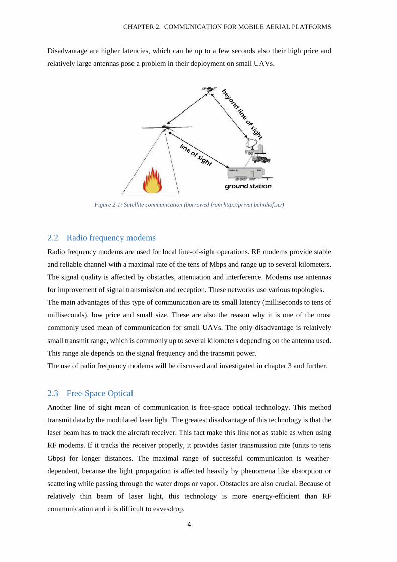
2.1 Satellites
When out of reach of direct data relays, also called Beyond-Line-of-Sight position, satellite
communication has to be used. During operations the satellite link needs to be available at all
times to provide reliable communications. Commercial satellites provide good link coverage and
reliable connection in areas between 70 degrees north and 70 degrees south. In extreme polar
regions is the satellite communication more complicated and requires special satellites.
CHAPTER 2. COMMUNICATION FOR MOBILE AERIAL PLATFORMS
4
Disadvantage are higher latencies, which can be up to a few seconds also their high price and
relatively large antennas pose a problem in their deployment on small UAVs.
Figure 2-1: Satellite communication (borrowed from http://privat.bahnhof.se/)
2.2 Radio frequency modems
Radio frequency modems are used for local line-of-sight operations. RF modems provide stable
and reliable channel with a maximal rate of the tens of Mbps and range up to several kilometers.
The signal quality is affected by obstacles, attenuation and interference. Modems use antennas
for improvement of signal transmission and reception. These networks use various topologies.
The main advantages of this type of communication are its small latency (milliseconds to tens of
milliseconds), low price and small size. These are also the reason why it is one of the most
commonly used mean of communication for small UAVs. The only disadvantage is relatively
small transmit range, which is commonly up to several kilometers depending on the antenna used.
This range ale depends on the signal frequency and the transmit power.
The use of radio frequency modems will be discussed and investigated in chapter 3 and further.
2.3 Free-Space Optical
Another line of sight mean of communication is free-space optical technology. This method
transmit data by the modulated laser light. The greatest disadvantage of this technology is that the
laser beam has to track the aircraft receiver. This fact make this link not as stable as when using
RF modems. If it tracks the receiver properly, it provides faster transmission rate (units to tens
Gbps) for longer distances. The maximal range of successful communication is weather-
dependent, because the light propagation is affected heavily by phenomena like absorption or
scattering while passing through the water drops or vapor. Obstacles are also crucial. Because of
relatively thin beam of laser light, this technology is more energy-efficient than RF
communication and it is difficult to eavesdrop.
CHAPTER 2. COMMUNICATION FOR MOBILE AERIAL PLATFORMS
5
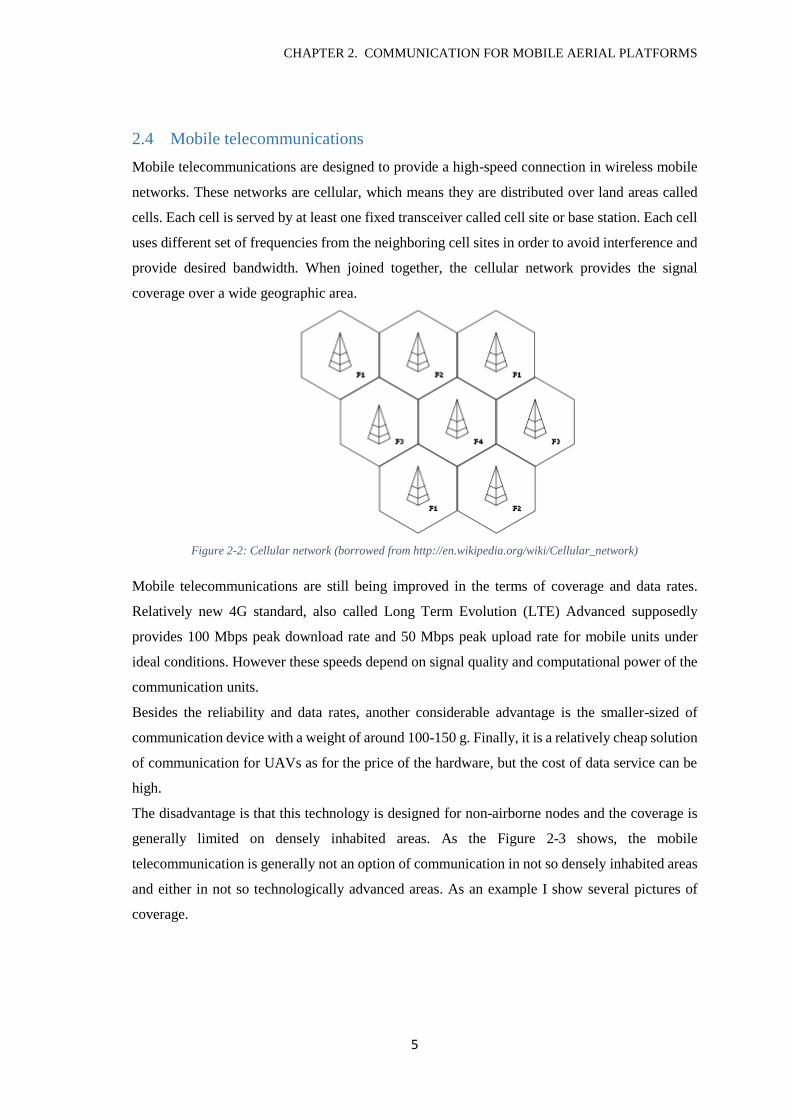
2.4 Mobile telecommunications
Mobile telecommunications are designed to provide a high-speed connection in wireless mobile
networks. These networks are cellular, which means they are distributed over land areas called
cells. Each cell is served by at least one fixed transceiver called cell site or base station. Each cell
uses different set of frequencies from the neighboring cell sites in order to avoid interference and
provide desired bandwidth. When joined together, the cellular network provides the signal
coverage over a wide geographic area.
Figure 2-2: Cellular network (borrowed from http://en.wikipedia.org/wiki/Cellular_network)
Mobile telecommunications are still being improved in the terms of coverage and data rates.
Relatively new 4G standard, also called Long Term Evolution (LTE) Advanced supposedly
provides 100 Mbps peak download rate and 50 Mbps peak upload rate for mobile units under
ideal conditions. However these speeds depend on signal quality and computational power of the
communication units.
Besides the reliability and data rates, another considerable advantage is the smaller-sized of
communication device with a weight of around 100-150 g. Finally, it is a relatively cheap solution
of communication for UAVs as for the price of the hardware, but the cost of data service can be
high.
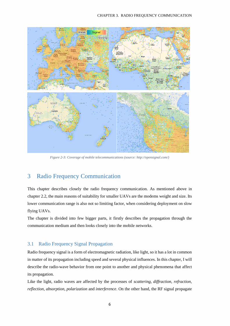
The disadvantage is that this technology is designed for non-airborne nodes and the coverage is
generally limited on densely inhabited areas. As the Figure 2-3 shows, the mobile
telecommunication is generally not an option of communication in not so densely inhabited areas
and either in not so technologically advanced areas. As an example I show several pictures of
coverage.
CHAPTER 3. RADIO FREQUENCY COMMUNICATION
6
Figure 2-3: Coverage of mobile telecommunications (source: http://opensignal.com/)
3 Radio Frequency Communication
This chapter describes closely the radio frequency communication. As mentioned above in
chapter 2.2, the main reasons of suitability for smaller UAVs are the modems weight and size. Its
lower communication range is also not so limiting factor, when considering deployment on slow
flying UAVs.
The chapter is divided into few bigger parts, it firstly describes the propagation through the
communication medium and then looks closely into the mobile networks.
3.1 Radio Frequency Signal Propagation
Radio frequency signal is a form of electromagnetic radiation, like light, so it has a lot in common
in matter of its propagation including speed and several physical influences. In this chapter, I will
describe the radio-wave behavior from one point to another and physical phenomena that affect
its propagation.
Like the light, radio waves are affected by the processes of scattering, diffraction, refraction,
reflection, absorption, polarization and interference. On the other hand, the RF signal propagate
CHAPTER 3. RADIO FREQUENCY COMMUNICATION
7
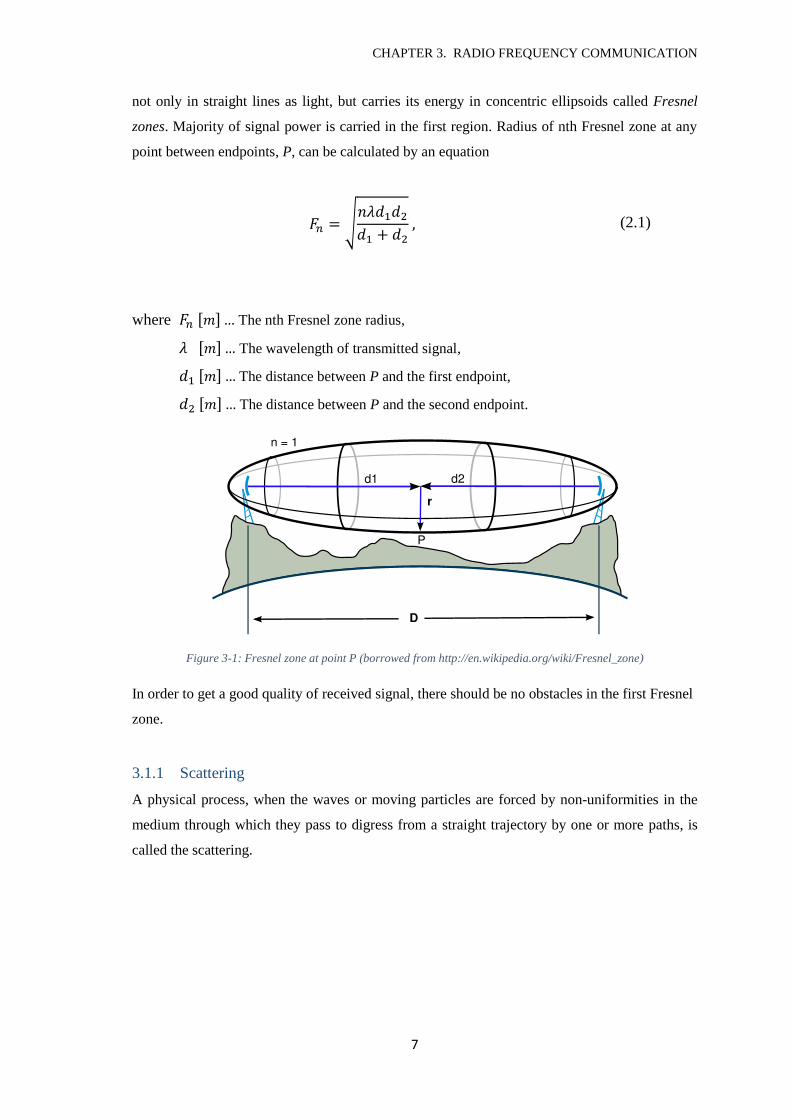
not only in straight lines as light, but carries its energy in concentric ellipsoids called Fresnel
zones. Majority of signal power is carried in the first region. Radius of nth Fresnel zone at any
point between endpoints, P, can be calculated by an equation
𝐹𝑛 = √𝑛𝜆𝑑1𝑑2
𝑑1 + 𝑑2 , (2.1)
where 𝐹𝑛 [𝑚] … The nth Fresnel zone radius,
𝜆 [𝑚] … The wavelength of transmitted signal,
𝑑1 [𝑚] … The distance between P and the first endpoint,
𝑑2 [𝑚] … The distance between P and the second endpoint.
Figure 3-1: Fresnel zone at point P (borrowed from http://en.wikipedia.org/wiki/Fresnel_zone)
In order to get a good quality of received signal, there should be no obstacles in the first Fresnel
zone.
3.1.1 Scattering
A physical process, when the waves or moving particles are forced by non-uniformities in the
medium through which they pass to digress from a straight trajectory by one or more paths, is
called the scattering.
CHAPTER 3. RADIO FREQUENCY COMMUNICATION
8
Figure 3-2: A Feynman diagram of scattering between two electrons by emission of a virtual photon. (borrowed from
http://en.wikipedia.org/wiki/Scattering)
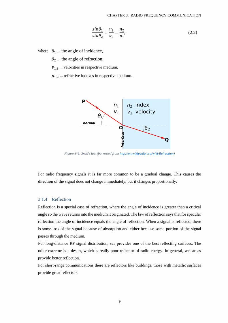
3.1.2 Diffraction
If the signals encounter an obstacle, they tend to travel around them. This can mean that the
received signal can have a ‘shaded’ source by an obstacle between transmitter and receiver.
Huygens-Fresnel Principle states that each point on a spherical wave front can be considered as a
source of a secondary wave front. That says that even though there will be a shadow zone behind
the obstacle, the signal will diffract around the obstacle and fill the space with a secondary waves.
Diffraction is more significant around sharper obstacles. The low frequency signals diffract more
than high frequency signals so the long-wave bands are able to provide coverage even in hilly
terrain.
Figure 3-3: Diffraction (borrowed from http://physics.taskermilward.org.uk/)
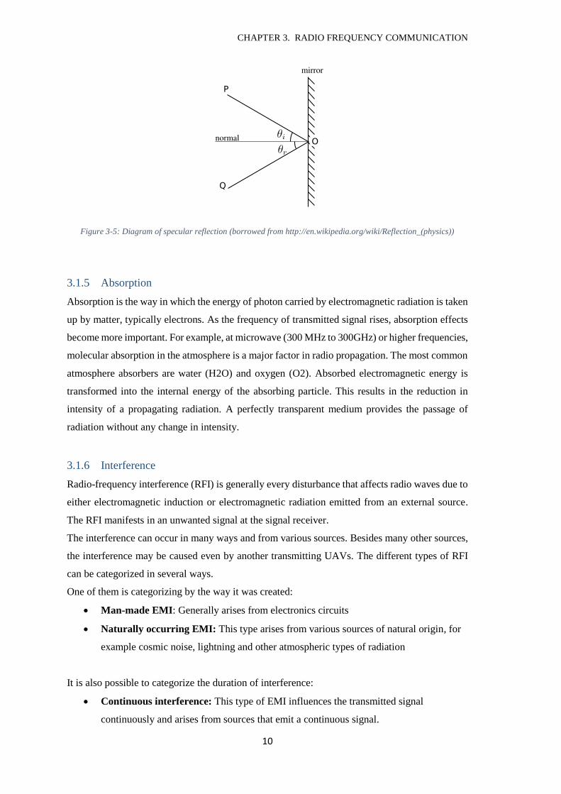
3.1.3 Refraction
It is found that the direction and speed of an electromagnetic wave changes when it moves from
a medium of one refractive index to another. This phenomenon is called the refraction. The
relations between angles of incidence and refraction and speeds or refractive indexes are
expressed by Snell's Law, that states
CHAPTER 3. RADIO FREQUENCY COMMUNICATION
9
𝑠𝑖𝑛𝜃1
𝑠𝑖𝑛𝜃2=
𝑣1
𝑣2=
𝑛2
𝑛1, (2.2)
where 𝜃1 … the angle of incidence,
𝜃2 … the angle of refraction,
𝑣1,2 … velocities in respective medium,
𝑛1,2 … refractive indexes in respective medium.
Figure 3-4: Snell's law (borrowed from http://en.wikipedia.org/wiki/Refraction)
For radio frequency signals it is far more common to be a gradual change. This causes the
direction of the signal does not change immediately, but it changes proportionally.
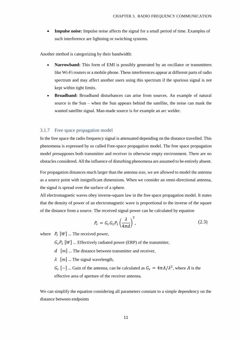
3.1.4 Reflection
Reflection is a special case of refraction, where the angle of incidence is greater than a critical
angle so the wave returns into the medium it originated. The law of reflection says that for specular
reflection the angle of incidence equals the angle of reflection. When a signal is reflected, there
is some loss of the signal because of absorption and either because some portion of the signal
passes through the medium.
For long-distance RF signal distribution, sea provides one of the best reflecting surfaces. The
other extreme is a desert, which is really poor reflector of radio energy. In general, wet areas
provide better reflection.
For short-range communications there are reflectors like buildings, those with metallic surfaces
provide great reflectors.
CHAPTER 3. RADIO FREQUENCY COMMUNICATION
10
Figure 3-5: Diagram of specular reflection (borrowed from http://en.wikipedia.org/wiki/Reflection_(physics))
3.1.5 Absorption
Absorption is the way in which the energy of photon carried by electromagnetic radiation is taken
up by matter, typically electrons. As the frequency of transmitted signal rises, absorption effects
become more important. For example, at microwave (300 MHz to 300GHz) or higher frequencies,
molecular absorption in the atmosphere is a major factor in radio propagation. The most common
atmosphere absorbers are water (H2O) and oxygen (O2). Absorbed electromagnetic energy is
transformed into the internal energy of the absorbing particle. This results in the reduction in
intensity of a propagating radiation. A perfectly transparent medium provides the passage of
radiation without any change in intensity.
3.1.6 Interference
Radio-frequency interference (RFI) is generally every disturbance that affects radio waves due to
either electromagnetic induction or electromagnetic radiation emitted from an external source.
The RFI manifests in an unwanted signal at the signal receiver.
The interference can occur in many ways and from various sources. Besides many other sources,
the interference may be caused even by another transmitting UAVs. The different types of RFI
can be categorized in several ways.
One of them is categorizing by the way it was created:
Man-made EMI: Generally arises from electronics circuits
Naturally occurring EMI: This type arises from various sources of natural origin, for
example cosmic noise, lightning and other atmospheric types of radiation
It is also possible to categorize the duration of interference:
Continuous interference: This type of EMI influences the transmitted signal
continuously and arises from sources that emit a continuous signal.
CHAPTER 3. RADIO FREQUENCY COMMUNICATION
11
Impulse noise: Impulse noise affects the signal for a small period of time. Examples of
such interference are lightning or switching systems.
Another method is categorizing by their bandwidth:
Narrowband: This form of EMI is possibly generated by an oscillator or transmitters
like Wi-Fi routers or a mobile phone. These interferences appear at different parts of radio
spectrum and may affect another users using this spectrum if the spurious signal is not
kept within tight limits.
Broadband: Broadband disturbances can arise from sources. An example of natural
source is the Sun – when the Sun appears behind the satellite, the noise can mask the
wanted satellite signal. Man-made source is for example an arc welder.
3.1.7 Free space propagation model
In the free space the radio frequency signal is attenuated depending on the distance travelled. This
phenomena is expressed by so called Free-space propagation model. The free space propagation
model presupposes both transmitter and receiver in otherwise empty environment. There are no
obstacles considered. All the influence of disturbing phenomena are assumed to be entirely absent.
For propagation distances much larger than the antenna size, we are allowed to model the antenna
as a source point with insignificant dimensions. When we consider an omni-directional antenna,
the signal is spread over the surface of a sphere.
All electromagnetic waves obey inverse-square law in the free space propagation model. It states
that the density of power of an electromagnetic wave is proportional to the inverse of the square
of the distance from a source. The received signal power can be calculated by equation
𝑃𝑟 = 𝐺𝑟𝐺𝑡𝑃𝑡 (𝜆
4𝜋𝑑)
2
, (2.3)
where 𝑃𝑟 [𝑊] … The received power,
𝐺𝑡𝑃𝑡 [𝑊] … Effectively radiated power (ERP) of the transmitter,
𝑑 [𝑚] … The distance between transmitter and receiver,
𝜆 [𝑚] … The signal wavelength,
𝐺𝑟 [−] … Gain of the antenna, can be calculated as 𝐺𝑟 = 4𝜋𝐴/𝜆2, where 𝐴 is the
effective area of aperture of the receiver antenna.
We can simplify the equation considering all parameters constant to a simple dependency on the
distance between endpoints
CHAPTER 3. RADIO FREQUENCY COMMUNICATION
12
𝑃𝑟 =𝐶𝑃𝑡
𝑑2. (2.4)
3.2 Parameters of signal quality
The signal propagation quality is a measurable by several physical quantities. Parameters
characterizing signal quality are Received Signal Strength Indication (RSSI), noise and Signal to
Noise Ratio (SNR). Before I describe these parameters, I will introduce the decibel units that
express it:
dB The decibel is a logarithmic unit used to express the ratio between two
values of a physical quantity. The ratio 𝑥 of the measured quantity 𝑃𝑥 to the
reference level 𝑃𝑟𝑒𝑓 is calculated using the formula
𝑥 = 10 log10 (𝑃𝑥
𝑃𝑟𝑒𝑓) 𝑑𝐵. (2.5)
dBm dB(mW) is a unit of power relative to 1 milliwatt (according to equation
𝑃𝑟𝑒𝑓 = 1𝑚𝑊).
dBi dB(isotropic) is the forward gain of an antenna compared with the
isotropic antenna (perfect omni-directional antenna)
Received Signal Strength Indication (also known as the Signal) is the usable strength of the radio
waves expressed in decibels. Larger values represents stronger signal.
Noise is a combination of all interfering signals, typically radio frequency interference. As RSSI,
it is also expressed in 𝑑𝐵𝑚. Again, lower values represents smaller noise that means there is
nearly no interference.
Signal to Noise Ratio is defined as the power ratio between useful power of signal (RSSI) and
interfering background noise. The relation is
𝑆𝑁𝑅𝑑𝐵 = 10 log10 (𝑃𝑠𝑖𝑔𝑛𝑎𝑙
𝑃𝑛𝑜𝑖𝑠𝑒) = 𝑃𝑠𝑖𝑔𝑛𝑎𝑙,𝑑𝐵 − 𝑃𝑛𝑜𝑖𝑠𝑒,𝑑𝐵. (2.6)
Transmission rate is also related with the signal quality measurement. The dependency of
transmission rate on channel bandwidth is specified by the Shannon-Hartley theorem.
3.2.1 Shannon–Hartley theorem
The Shannon–Hartley theorem tells the maximum rate at which information can be transmitted
over a communications channel of a specified bandwidth in the presence of noise.
CHAPTER 3. RADIO FREQUENCY COMMUNICATION
13
The theorem states the tightest upper bound of the information rate C of clean data that can be
sent with a given signal power S via the medium of bandwidth B with a presence of noise of
power N:
𝐶 = 𝐵 𝑙𝑜𝑔2 (1 +𝑆
𝑁), (2.7)
where 𝐶 [𝑏𝑝𝑠] … The channel capacity,
𝐵 [𝐻𝑧] … The bandwidth of the channel,
𝑆 [𝑊] … The average received signal power over the bandwidth,
𝑁 [𝑊] … The average noise or interference power over the bandwidth,
𝑆/𝑁 is also called signal-to-noise ratio (SNR) expressed as a linear power ratio.
This states the tight upper bound of the rate, the real rates are at the moment a fraction of this
value.
3.3 Wireless mobile networks
Wireless mobile network is a decentralized type of ad-hoc wireless network, which means that it
does not have a pre-existing infrastructure. The infrastructure is made dynamically, as each node
forwards data to nearest nodes which can move.
The signal availability is affected by several influences like node location, channel selection, and
interference from other nodes.
3.3.1 Signal availability problems
The problem of wireless networks is that the transmitter know channel usage conditions only in
its neighborhood and has no information about the situation at the receiver. This results in two
typical problems of wireless communication; the hidden node problem and the exposed node
problem.
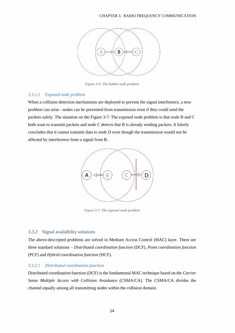
3.3.1.1 Hidden node problem
A hidden node in wireless networks refers to a node that is out of range of other nodes. The hidden
node situation occurs when a node visible from a wireless access point is not visible from other
nodes communicating with the access point.
The situation on the Figure 3-6: The hidden node problem is that node A and C are hidden from
each other, which results in inability to detect a signal collision while transmitting. The problem
occurs when both node A and node C start to send packets simultaneously resulting in signal
interference and packet loss.
CHAPTER 3. RADIO FREQUENCY COMMUNICATION
14
Figure 3-6: The hidden node problem
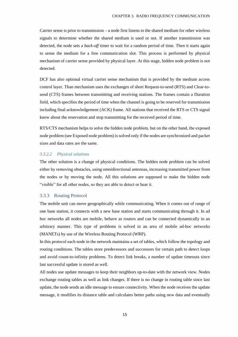
3.3.1.2 Exposed node problem
When a collision detection mechanisms are deployed to prevent the signal interference, a new
problem can arise - nodes can be prevented from transmission even if they could send the
packets safely. The situation on the Figure 3-7: The exposed node problem is that node B and C
both want to transmit packets and node C detects that B is already sending packets. It falsely
concludes that it cannot transmit data to node D even though the transmission would not be
affected by interference from a signal from B.
Figure 3-7: The exposed node problem
3.3.2 Signal availability solutions
The above-descripted problems are solved in Medium Access Control (MAC) layer. There are
three standard solutions – Distributed coordination function (DCF), Point coordination function
(PCF) and Hybrid coordination function (HCF).
3.3.2.1 Distributed coordination function
Distributed coordination function (DCF) is the fundamental MAC technique based on the Carrier
Sense Multiple Access with Collision Avoidance (CSMA/CA). The CSMA/CA divides the
channel equally among all transmitting nodes within the collision domain.
CHAPTER 3. RADIO FREQUENCY COMMUNICATION
15
Carrier sense is prior to transmission – a node first listens to the shared medium for other wireless
signals to determine whether the shared medium is used or not. If another transmission was
detected, the node sets a back-off timer to wait for a random period of time. Then it starts again
to sense the medium for a free communication slot. This process is performed by physical
mechanism of carrier sense provided by physical layer. At this stage, hidden node problem is not
detected.
DCF has also optional virtual carrier sense mechanism that is provided by the medium access
control layer. Than mechanism uses the exchanges of short Request-to-send (RTS) and Clear-to-
send (CTS) frames between transmitting and receiving stations. The frames contain a Duration
field, which specifies the period of time when the channel is going to be reserved for transmission
including final acknowledgement (ACK) frame. All stations that received the RTS or CTS signal
know about the reservation and stop transmitting for the received period of time.
RTS/CTS mechanism helps to solve the hidden node problem, but on the other hand, the exposed
node problem (see Exposed node problem) is solved only if the nodes are synchronized and packet
sizes and data rates are the same.
3.3.2.2 Physical solutions
The other solution is a change of physical conditions. The hidden node problem can be solved
either by removing obstacles, using omnidirectional antennas, increasing transmitted power from
the nodes or by moving the node. All this solutions are supposed to make the hidden node
“visible” for all other nodes, so they are able to detect or hear it.
3.3.3 Routing Protocol
The mobile unit can move geographically while communicating. When it comes out of range of
one base station, it connects with a new base station and starts communicating through it. In ad
hoc networks all nodes are mobile, behave as routers and can be connected dynamically in an
arbitrary manner. This type of problems is solved in an area of mobile ad-hoc networks
(MANETs) by use of the Wireless Routing Protocol (WRP).
In this protocol each node in the network maintains a set of tables, which follow the topology and
routing conditions. The tables store predecessors and successors for certain path to detect loops
and avoid count-to-infinity problems. To detect link breaks, a number of update timeouts since
last successful update is stored as well.
All nodes use update messages to keep their neighbors up-to-date with the network view. Nodes
exchange routing tables as well as link changes. If there is no change in routing table since last
update, the node sends an idle message to ensure connectivity. When the node receives the update
message, it modifies its distance table and calculates better paths using new data and eventually
CHAPTER 4. IMPLEMENTATION
16
updates the routing table when the new path is better than the existing one. Any new path is
relayed back so that the original nodes can update their tables.
3.4 Frequency bands
Radio frequency bands are limited shared medium so there rise a need of regulation. RF bands
are regulated by several organizations. The main regulator is International Telecommunication
Union (ITU). This organization coordinates the shared global use of the radio spectrum.
Furthermore, there are regional authorities that regulate radio spectrum more specifically. The
bands are managed by a lot of organizations, which administrate the spectrum in the specific
regions. For example, in Europe is the spectrum managed by European Union, The Independent
Regulators Group (IRG), The European Conference of Postal and Telecommunications
Administrations (CEPT) or Energy Regulatory Office (ERO). Each country has also its own
regulatory input, in the Czech Republic the responsible organization is Český Telekomunikační
Úřad (ČTÚ).
3.4.1 Allowed frequencies
For aerial communication purposes the ČTÚ allows public to use RF bands described further.
Each band has also its specific term of use like maximal effectively radiated power and other
restrictions. The possible frequencies for unmanned vehicles are for category of non-specified
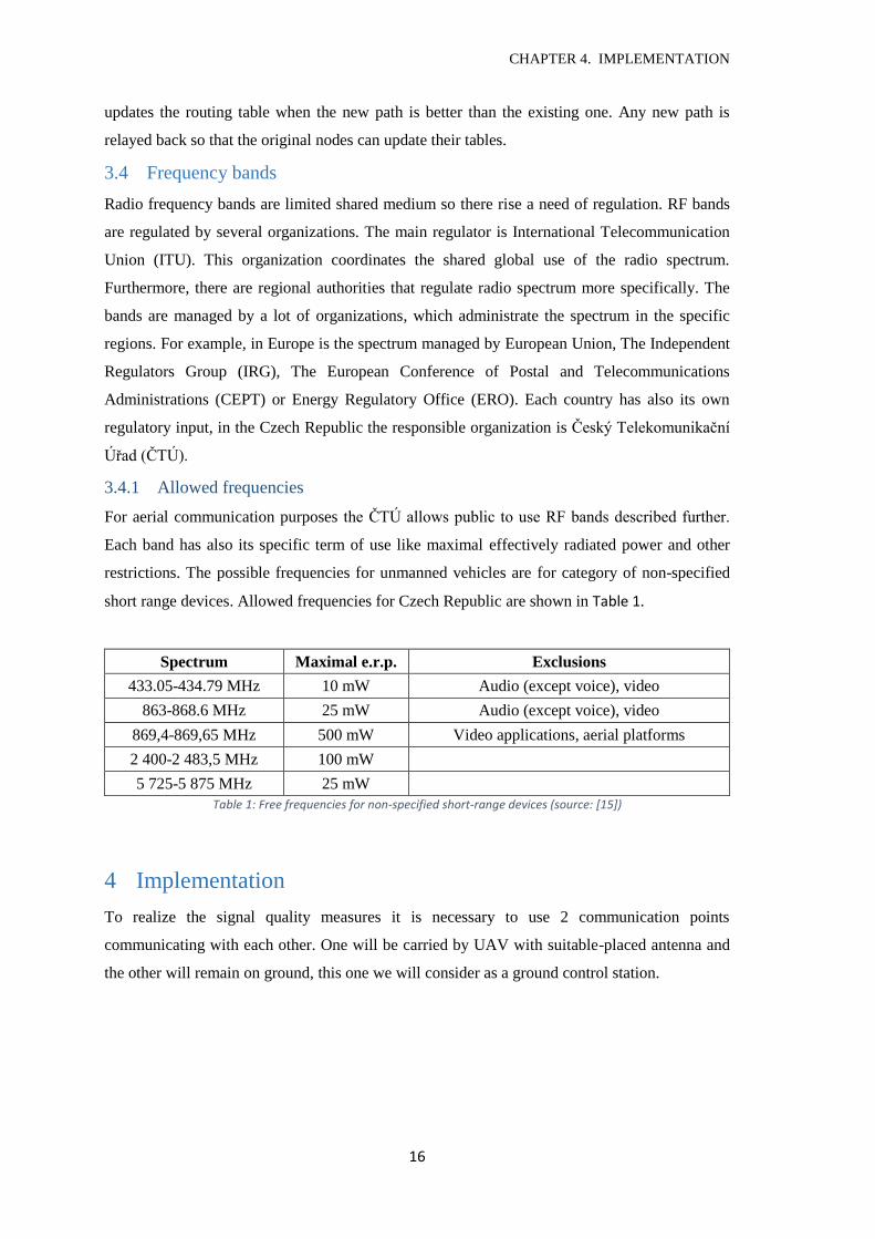
short range devices. Allowed frequencies for Czech Republic are shown in Table 1.
Spectrum Maximal e.r.p. Exclusions
433.05-434.79 MHz 10 mW Audio (except voice), video
863-868.6 MHz 25 mW Audio (except voice), video
869,4-869,65 MHz 500 mW Video applications, aerial platforms
2 400-2 483,5 MHz 100 mW
5 725-5 875 MHz 25 mW
Table 1: Free frequencies for non-specified short-range devices (source: [15])
4 Implementation
To realize the signal quality measures it is necessary to use 2 communication points
communicating with each other. One will be carried by UAV with suitable-placed antenna and
the other will remain on ground, this one we will consider as a ground control station.
CHAPTER 4. IMPLEMENTATION
17
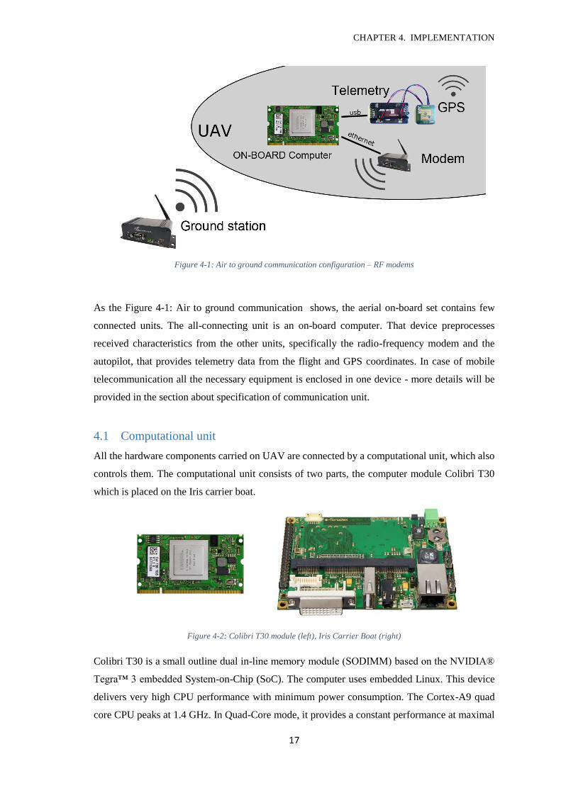
Figure 4-1: Air to ground communication configuration – RF modems
As the Figure 4-1: Air to ground communication shows, the aerial on-board set contains few
connected units. The all-connecting unit is an on-board computer. That device preprocesses
received characteristics from the other units, specifically the radio-frequency modem and the
autopilot, that provides telemetry data from the flight and GPS coordinates. In case of mobile
telecommunication all the necessary equipment is enclosed in one device - more details will be
provided in the section about specification of communication unit.
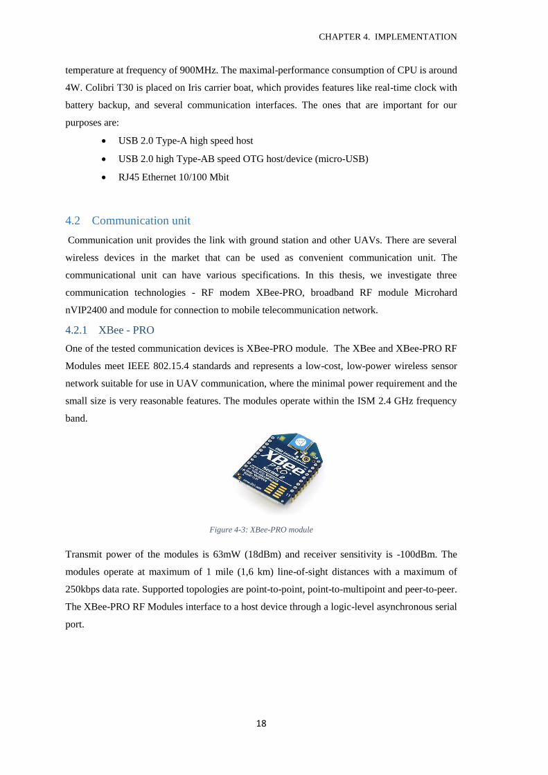
4.1 Computational unit
All the hardware components carried on UAV are connected by a computational unit, which also
controls them. The computational unit consists of two parts, the computer module Colibri T30
which is placed on the Iris carrier boat.
Figure 4-2: Colibri T30 module (left), Iris Carrier Boat (right)
Colibri T30 is a small outline dual in-line memory module (SODIMM) based on the NVIDIA®
Tegra™ 3 embedded System-on-Chip (SoC). The computer uses embedded Linux. This device
delivers very high CPU performance with minimum power consumption. The Cortex-A9 quad
core CPU peaks at 1.4 GHz. In Quad-Core mode, it provides a constant performance at maximal
CHAPTER 4. IMPLEMENTATION
18
temperature at frequency of 900MHz. The maximal-performance consumption of CPU is around
4W. Colibri T30 is placed on Iris carrier boat, which provides features like real-time clock with
battery backup, and several communication interfaces. The ones that are important for our
purposes are:
USB 2.0 Type-A high speed host
USB 2.0 high Type-AB speed OTG host/device (micro-USB)
RJ45 Ethernet 10/100 Mbit
4.2 Communication unit
Communication unit provides the link with ground station and other UAVs. There are several
wireless devices in the market that can be used as convenient communication unit. The
communicational unit can have various specifications. In this thesis, we investigate three
communication technologies - RF modem XBee-PRO, broadband RF module Microhard
nVIP2400 and module for connection to mobile telecommunication network.
4.2.1 XBee - PRO
One of the tested communication devices is XBee-PRO module. The XBee and XBee-PRO RF
Modules meet IEEE 802.15.4 standards and represents a low-cost, low-power wireless sensor
network suitable for use in UAV communication, where the minimal power requirement and the
small size is very reasonable features. The modules operate within the ISM 2.4 GHz frequency
band.
Figure 4-3: XBee-PRO module
Transmit power of the modules is 63mW (18dBm) and receiver sensitivity is -100dBm. The
modules operate at maximum of 1 mile (1,6 km) line-of-sight distances with a maximum of
250kbps data rate. Supported topologies are point-to-point, point-to-multipoint and peer-to-peer.
The XBee-PRO RF Modules interface to a host device through a logic-level asynchronous serial
port.
CHAPTER 4. IMPLEMENTATION
19
4.2.2 Microhard nVIP2400
The representative of small RF modems is Microhard nVIP2400. This modem is suitable for aerial
platforms not only for its smaller size and weight (around 80 g), but also for its opportunities of
network adjustments like free topology specification and communication interface.
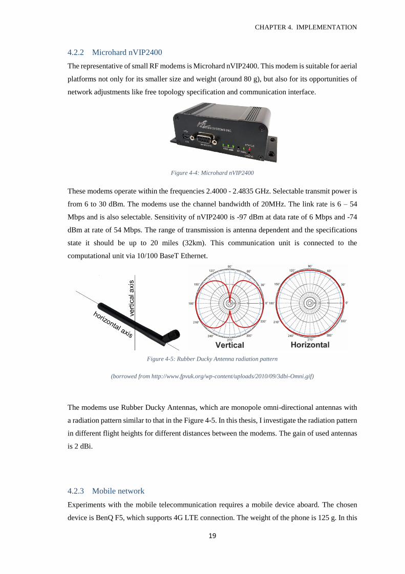
Figure 4-4: Microhard nVIP2400
These modems operate within the frequencies 2.4000 - 2.4835 GHz. Selectable transmit power is
from 6 to 30 dBm. The modems use the channel bandwidth of 20MHz. The link rate is 6 – 54
Mbps and is also selectable. Sensitivity of nVIP2400 is -97 dBm at data rate of 6 Mbps and -74
dBm at rate of 54 Mbps. The range of transmission is antenna dependent and the specifications
state it should be up to 20 miles (32km). This communication unit is connected to the
computational unit via 10/100 BaseT Ethernet.
Figure 4-5: Rubber Ducky Antenna radiation pattern
(borrowed from http://www.fpvuk.org/wp-content/uploads/2010/09/3dbi-Omni.gif)
The modems use Rubber Ducky Antennas, which are monopole omni-directional antennas with
a radiation pattern similar to that in the Figure 4-5. In this thesis, I investigate the radiation pattern
in different flight heights for different distances between the modems. The gain of used antennas
is 2 dBi.
4.2.3 Mobile network
Experiments with the mobile telecommunication requires a mobile device aboard. The chosen
device is BenQ F5, which supports 4G LTE connection. The weight of the phone is 125 g. In this
CHAPTER 4. IMPLEMENTATION
20
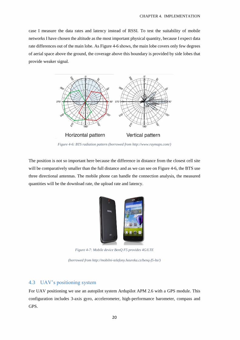
case I measure the data rates and latency instead of RSSI. To test the suitability of mobile
networks I have chosen the altitude as the most important physical quantity, because I expect data
rate differences out of the main lobe. As Figure 4-6 shows, the main lobe covers only few degrees
of aerial space above the ground, the coverage above this boundary is provided by side lobes that
provide weaker signal.
Figure 4-6: BTS radiation pattern (borrowed from http://www.raymaps.com/)
The position is not so important here because the difference in distance from the closest cell site
will be comparatively smaller than the full distance and as we can see on Figure 4-6, the BTS use
three directional antennas. The mobile phone can handle the connection analysis, the measured
quantities will be the download rate, the upload rate and latency.
Figure 4-7: Mobile device BenQ F5 provides 4G/LTE
(borrowed from http://mobilni-telefony.heureka.cz/benq-f5-lte/)
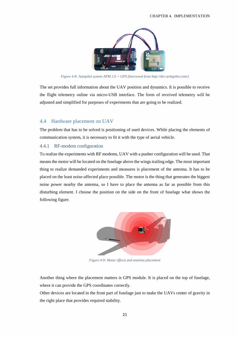
4.3 UAV’s positioning system
For UAV positioning we use an autopilot system Ardupilot APM 2.6 with a GPS module. This
configuration includes 3-axis gyro, accelerometer, high-performance barometer, compass and
GPS.
CHAPTER 4. IMPLEMENTATION
21
Figure 4-8: Autopilot system APM 2.6 + GPS (borrowed from http://dev.ardupilot.com/)
The set provides full information about the UAV position and dynamics. It is possible to receive
the flight telemetry online via micro-USB interface. The form of received telemetry will be
adjusted and simplified for purposes of experiments that are going to be realized.
4.4 Hardware placement on UAV
The problem that has to be solved is positioning of used devices. While placing the elements of
communication system, it is necessary to fit it with the type of aerial vehicle.
4.4.1 RF-modem configuration
To realize the experiments with RF modems, UAV with a pusher configuration will be used. That
means the motor will be located on the fuselage above the wings trailing edge. The most important
thing to realize demanded experiments and measures is placement of the antenna. It has to be
placed on the least noise-affected place possible. The motor is the thing that generates the biggest
noise power nearby the antenna, so I have to place the antenna as far as possible from this
disturbing element. I choose the position on the side on the front of fuselage what shows the
following figure.
Figure 4-9: Motor effects and antenna placement
Another thing where the placement matters is GPS module. It is placed on the top of fuselage,
where it can provide the GPS coordinates correctly.
Other devices are located in the front part of fuselage just to make the UAVs center of gravity in
the right place that provides required stability.
CHAPTER 4. IMPLEMENTATION
22
Figure 4-10: UAV for RF modems communication
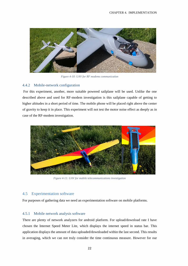
4.4.2 Mobile-network configuration
For this experiment, another, more suitable powered sailplane will be used. Unlike the one
described above and used for RF-modem investigation is this sailplane capable of getting to
higher altitudes in a short period of time. The mobile phone will be placed right above the center
of gravity to keep it in place. This experiment will not test the motor noise effect as deeply as in
case of the RF-modem investigation.
Figure 4-11: UAV for mobile telecommunications investigation
4.5 Experimentation software
For purposes of gathering data we need an experimentation software on mobile platforms.
4.5.1 Mobile network analysis software
There are plenty of network analyzers for android platform. For upload/download rate I have
chosen the Internet Speed Meter Lite, which displays the internet speed in status bar. This
application displays the amount of data uploaded/downloaded within the last second. This results
in averaging, which we can not truly consider the time continuous measure. However for our
CHAPTER 4. IMPLEMENTATION
23
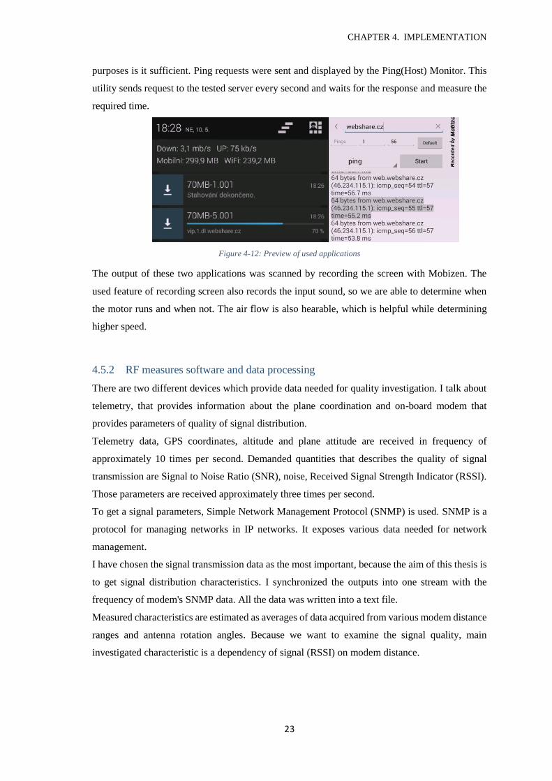
purposes is it sufficient. Ping requests were sent and displayed by the Ping(Host) Monitor. This
utility sends request to the tested server every second and waits for the response and measure the
required time.
Figure 4-12: Preview of used applications
The output of these two applications was scanned by recording the screen with Mobizen. The
used feature of recording screen also records the input sound, so we are able to determine when
the motor runs and when not. The air flow is also hearable, which is helpful while determining
higher speed.
4.5.2 RF measures software and data processing
There are two different devices which provide data needed for quality investigation. I talk about
telemetry, that provides information about the plane coordination and on-board modem that
provides parameters of quality of signal distribution.
Telemetry data, GPS coordinates, altitude and plane attitude are received in frequency of
approximately 10 times per second. Demanded quantities that describes the quality of signal
transmission are Signal to Noise Ratio (SNR), noise, Received Signal Strength Indicator (RSSI).
Those parameters are received approximately three times per second.
To get a signal parameters, Simple Network Management Protocol (SNMP) is used. SNMP is a
protocol for managing networks in IP networks. It exposes various data needed for network
management.
I have chosen the signal transmission data as the most important, because the aim of this thesis is
to get signal distribution characteristics. I synchronized the outputs into one stream with the
frequency of modem's SNMP data. All the data was written into a text file.
Measured characteristics are estimated as averages of data acquired from various modem distance
ranges and antenna rotation angles. Because we want to examine the signal quality, main
investigated characteristic is a dependency of signal (RSSI) on modem distance.
CHAPTER 5. EXPERIMENTS
24
5 Experiments
In this chapter, I am going to explain the designed experiments to test the examined devices. I
begin with measured quantities and continue with description of experiment scenarios and settings
and finally I will present experiment results.
5.1 Physical quantities
In mobile telecommunication investigation we will mainly need the internet data rates. These are
collected by applications described in chapter 4.5.1. Altitude will be estimated with knowledge
of rate of climb and rate of sink. Another investigated quantity is motor run, which is determined
from the recorded sound. The recorded sound also helps in determination of relatively higher
speed pass, which will also take part in the experiment.
The quantities of importance in RF-modem experiments are the receiver antenna position relative
to the antenna of transmitter and the signal quality parameters (see 3.3). The parameter of signal
quality I have chosen as important is RSSI. Relative position of antenna consist of two quantities,
the distance between antennas and the relative antenna rotation. The distance will be calculated
from the Cartesian coordinates given from the autopilot as a Euclidean distance from the point
where the ground station is. The antenna rotation calculation is more complicated and described
in the following chapter.
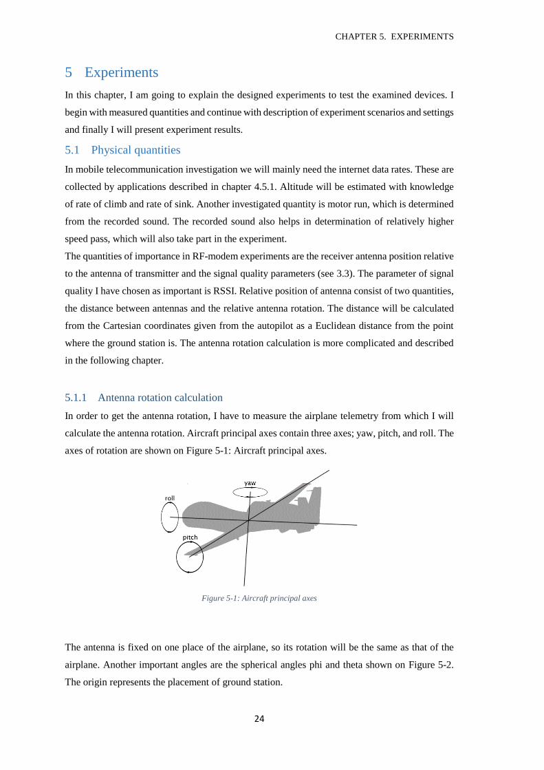
5.1.1 Antenna rotation calculation
In order to get the antenna rotation, I have to measure the airplane telemetry from which I will
calculate the antenna rotation. Aircraft principal axes contain three axes; yaw, pitch, and roll. The
axes of rotation are shown on Figure 5-1: Aircraft principal axes.
Figure 5-1: Aircraft principal axes
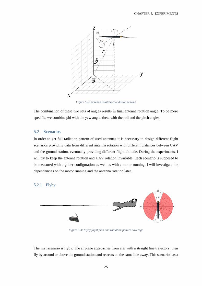
The antenna is fixed on one place of the airplane, so its rotation will be the same as that of the
airplane. Another important angles are the spherical angles phi and theta shown on Figure 5-2.
The origin represents the placement of ground station.
CHAPTER 5. EXPERIMENTS
25
Figure 5-2: Antenna rotation calculation scheme
The combination of these two sets of angles results in final antenna rotation angle. To be more
specific, we combine phi with the yaw angle, theta with the roll and the pitch angles.
5.2 Scenarios
In order to get full radiation pattern of used antennas it is necessary to design different flight
scenarios providing data from different antenna rotation with different distances between UAV
and the ground station, eventually providing different flight altitude. During the experiments, I
will try to keep the antenna rotation and UAV rotation invariable. Each scenario is supposed to
be measured with a glider configuration as well as with a motor running. I will investigate the
dependencies on the motor running and the antenna rotation later.
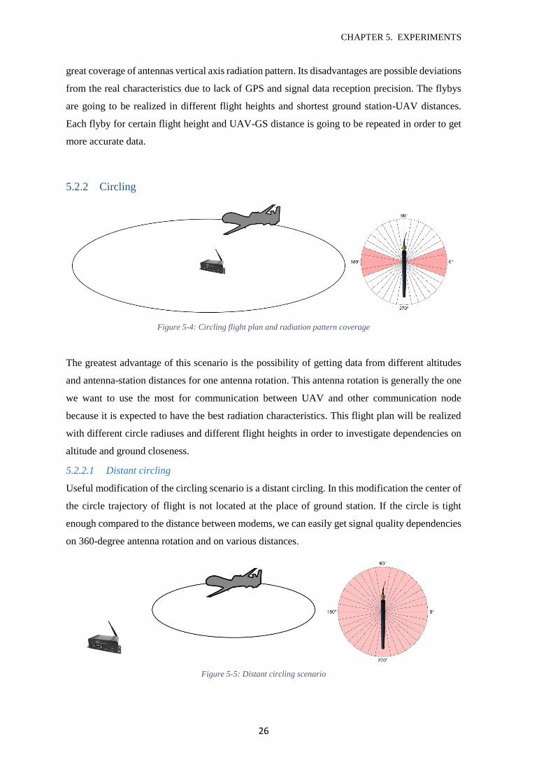
5.2.1 Flyby
Figure 5-3: Flyby flight plan and radiation pattern coverage
The first scenario is flyby. The airplane approaches from afar with a straight line trajectory, then
fly by around or above the ground station and retreats on the same line away. This scenario has a
CHAPTER 5. EXPERIMENTS
26
great coverage of antennas vertical axis radiation pattern. Its disadvantages are possible deviations
from the real characteristics due to lack of GPS and signal data reception precision. The flybys
are going to be realized in different flight heights and shortest ground station-UAV distances.
Each flyby for certain flight height and UAV-GS distance is going to be repeated in order to get
more accurate data.
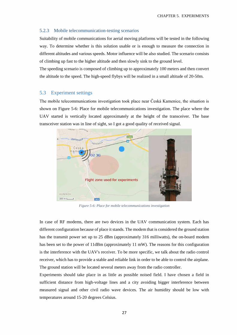
5.2.2 Circling
Figure 5-4: Circling flight plan and radiation pattern coverage
The greatest advantage of this scenario is the possibility of getting data from different altitudes
and antenna-station distances for one antenna rotation. This antenna rotation is generally the one
we want to use the most for communication between UAV and other communication node
because it is expected to have the best radiation characteristics. This flight plan will be realized
with different circle radiuses and different flight heights in order to investigate dependencies on
altitude and ground closeness.
5.2.2.1 Distant circling
Useful modification of the circling scenario is a distant circling. In this modification the center of
the circle trajectory of flight is not located at the place of ground station. If the circle is tight
enough compared to the distance between modems, we can easily get signal quality dependencies
on 360-degree antenna rotation and on various distances.
Figure 5-5: Distant circling scenario
CHAPTER 5. EXPERIMENTS
27
5.2.3 Mobile telecommunication-testing scenarios
Suitability of mobile communications for aerial moving platforms will be tested in the following
way. To determine whether is this solution usable or is enough to measure the connection in
different altitudes and various speeds. Motor influence will be also studied. The scenario consists
of climbing up fast to the higher altitude and then slowly sink to the ground level.
The speeding scenario is composed of climbing up to approximately 100 meters and then convert
the altitude to the speed. The high-speed flybys will be realized in a small altitude of 20-50m.
5.3 Experiment settings
The mobile telecommunications investigation took place near Česká Kamenice, the situation is
shown on Figure 5-6: Place for mobile telecommunications investigation. The place where the
UAV started is vertically located approximately at the height of the transceiver. The base
transceiver station was in line of sight, so I got a good quality of received signal.
Figure 5-6: Place for mobile telecommunications investigation
In case of RF modems, there are two devices in the UAV communication system. Each has
different configuration because of place it stands. The modem that is considered the ground station
has the transmit power set up to 25 dBm (approximately 316 milliwatts), the on-board modem
has been set to the power of 11dBm (approximately 11 mW). The reasons for this configuration
is the interference with the UAV's receiver. To be more specific, we talk about the radio control
receiver, which has to provide a stable and reliable link in order to be able to control the airplane.
The ground station will be located several meters away from the radio controller.
Experiments should take place in as little as possible noised field. I have chosen a field in
sufficient distance from high-voltage lines and a city avoiding bigger interference between
measured signal and other civil radio wave devices. The air humidity should be low with
temperatures around 15-20 degrees Celsius.
CHAPTER 5. EXPERIMENTS
28
5.4 Results and comparison
Now it is time to present the results of experiments described above. This chapter firstly presents
the results of measures in mobile communications, then moves to RF modems and finally
compares results of both solutions. The results of RF modems communication will be also
compared to results of xBee PRO platform from external source.
5.4.1 Mobile telecommunications
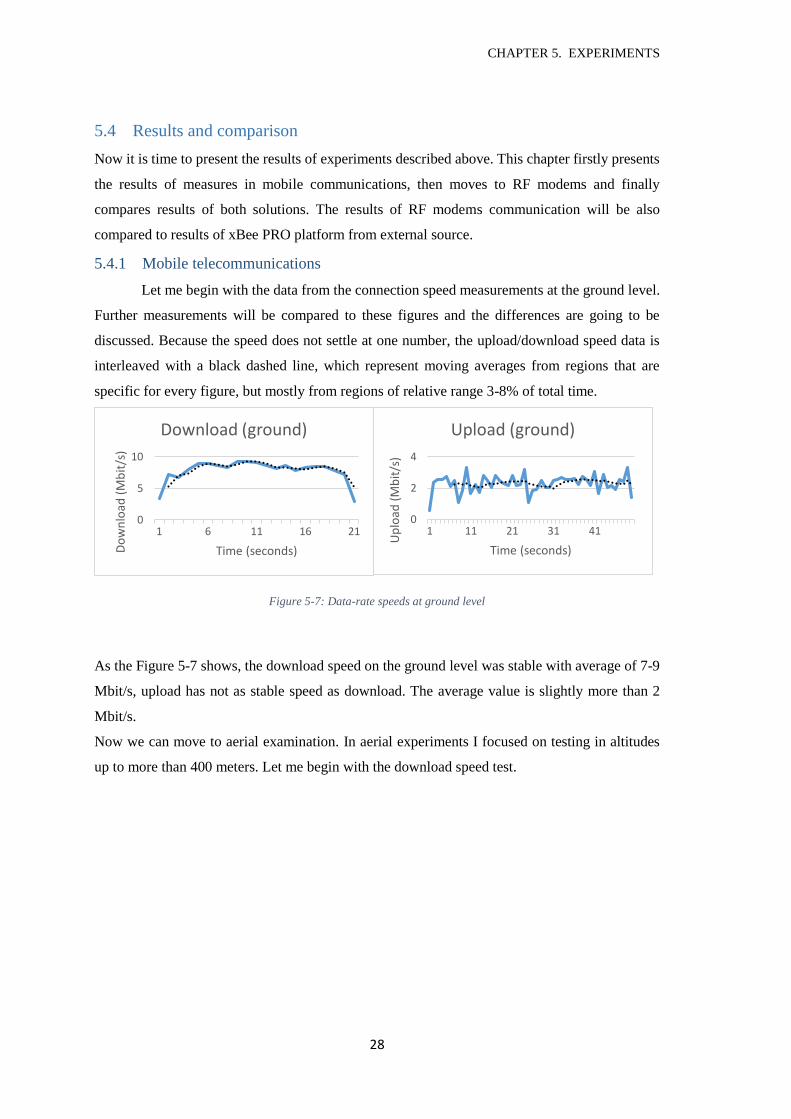
Let me begin with the data from the connection speed measurements at the ground level.
Further measurements will be compared to these figures and the differences are going to be
discussed. Because the speed does not settle at one number, the upload/download speed data is
interleaved with a black dashed line, which represent moving averages from regions that are
specific for every figure, but mostly from regions of relative range 3-8% of total time.
Figure 5-7: Data-rate speeds at ground level
As the Figure 5-7 shows, the download speed on the ground level was stable with average of 7-9
Mbit/s, upload has not as stable speed as download. The average value is slightly more than 2
Mbit/s.
Now we can move to aerial examination. In aerial experiments I focused on testing in altitudes
up to more than 400 meters. Let me begin with the download speed test.
0
5
10
1 6 11 16 21
Do
wn
load
(M
bit
/s)
Time (seconds)
Download (ground)
0
2
4
1 11 21 31 41
Up
load
(M
bit
/s)
Time (seconds)
Upload (ground)
CHAPTER 5. EXPERIMENTS
29
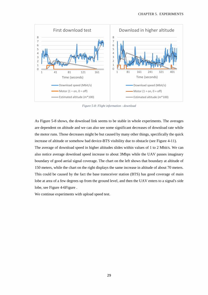
Figure 5-8: Flight information - download
As Figure 5-8 shows, the download link seems to be stable in whole experiments. The averages
are dependent on altitude and we can also see some significant decreases of download rate while
the motor runs. Those decreases might be but caused by many other things, specifically the quick
increase of altitude or somehow bad device-BTS visibility due to obstacle (see Figure 4-11).
The average of download speed in higher altitudes slides within values of 1 to 2 Mbit/s. We can
also notice average download speed increase to about 3Mbps while the UAV passes imaginary
boundary of good aerial signal coverage. The chart on the left shows that boundary at altitude of
150 meters, while the chart on the right displays the same increase in altitude of about 70 meters.
This could be caused by the fact the base transceiver station (BTS) has good coverage of main
lobe at area of a few degrees up from the ground level, and then the UAV enters to a signal's side
lobe, see Figure 4-6Figure .
We continue experiments with upload speed test.
0
1
2
3
4
5
6
7
8
1 41 81 121 161
Time (seconds)
First download test
Download speed (Mbit/s)
Motor (1 = on, 0 = off)
Estimated altitude (m*100)
012345678
1 81 161 241 321 401
Time (seconds)
Download in higher altitude
Download speed (Mbit/s)
Motor (1 = on, 0 = off)
Estimated altitude (m*100)
CHAPTER 5. EXPERIMENTS
30
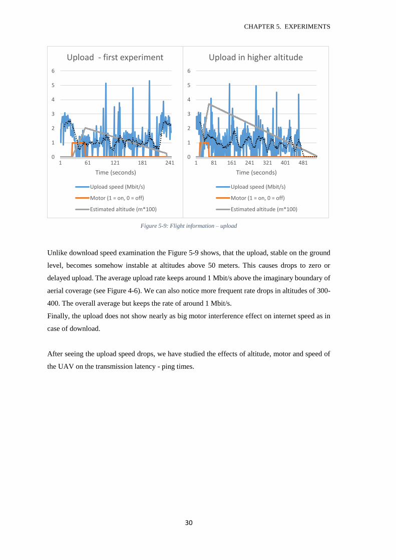
Figure 5-9: Flight information – upload
Unlike download speed examination the Figure 5-9 shows, that the upload, stable on the ground
level, becomes somehow instable at altitudes above 50 meters. This causes drops to zero or
delayed upload. The average upload rate keeps around 1 Mbit/s above the imaginary boundary of
aerial coverage (see Figure 4-6). We can also notice more frequent rate drops in altitudes of 300-
400. The overall average but keeps the rate of around 1 Mbit/s.
Finally, the upload does not show nearly as big motor interference effect on internet speed as in
case of download.
After seeing the upload speed drops, we have studied the effects of altitude, motor and speed of
the UAV on the transmission latency - ping times.
0
1
2
3
4
5
6
1 61 121 181 241
Time (seconds)
Upload - first experiment
Upload speed (Mbit/s)
Motor (1 = on, 0 = off)
Estimated altitude (m*100)
0
1
2
3
4
5
6
1 81 161 241 321 401 481
Time (seconds)
Upload in higher altitude
Upload speed (Mbit/s)
Motor (1 = on, 0 = off)
Estimated altitude (m*100)
CHAPTER 5. EXPERIMENTS
31
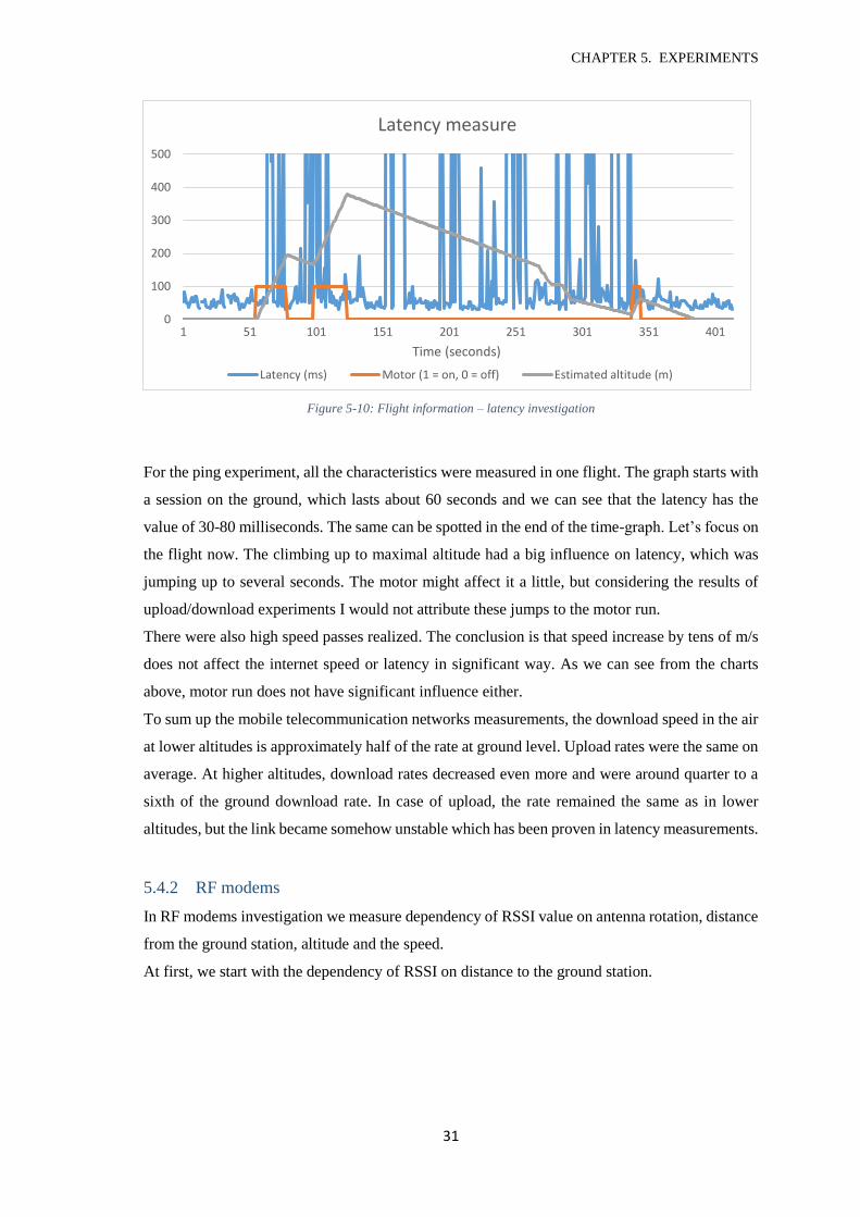
Figure 5-10: Flight information – latency investigation
For the ping experiment, all the characteristics were measured in one flight. The graph starts with
a session on the ground, which lasts about 60 seconds and we can see that the latency has the
value of 30-80 milliseconds. The same can be spotted in the end of the time-graph. Let’s focus on
the flight now. The climbing up to maximal altitude had a big influence on latency, which was
jumping up to several seconds. The motor might affect it a little, but considering the results of
upload/download experiments I would not attribute these jumps to the motor run.
There were also high speed passes realized. The conclusion is that speed increase by tens of m/s
does not affect the internet speed or latency in significant way. As we can see from the charts
above, motor run does not have significant influence either.
To sum up the mobile telecommunication networks measurements, the download speed in the air
at lower altitudes is approximately half of the rate at ground level. Upload rates were the same on
average. At higher altitudes, download rates decreased even more and were around quarter to a
sixth of the ground download rate. In case of upload, the rate remained the same as in lower
altitudes, but the link became somehow unstable which has been proven in latency measurements.
5.4.2 RF modems
In RF modems investigation we measure dependency of RSSI value on antenna rotation, distance
from the ground station, altitude and the speed.
At first, we start with the dependency of RSSI on distance to the ground station.
0
100
200
300
400
500
1 51 101 151 201 251 301 351 401
Time (seconds)
Latency measure
Latency (ms) Motor (1 = on, 0 = off) Estimated altitude (m)
CHAPTER 5. EXPERIMENTS
32
Figure 5-11: RSSI vs. Distance to the ground station (RF)
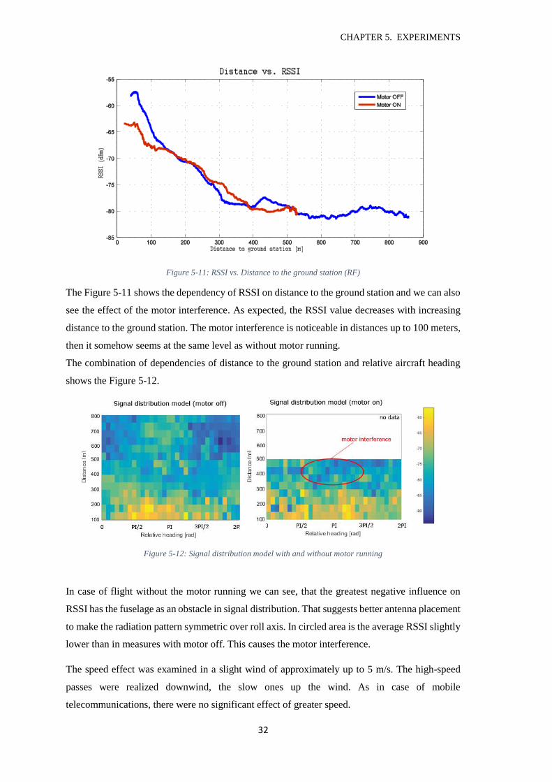
The Figure 5-11 shows the dependency of RSSI on distance to the ground station and we can also
see the effect of the motor interference. As expected, the RSSI value decreases with increasing
distance to the ground station. The motor interference is noticeable in distances up to 100 meters,
then it somehow seems at the same level as without motor running.
The combination of dependencies of distance to the ground station and relative aircraft heading
shows the Figure 5-12.
Figure 5-12: Signal distribution model with and without motor running
In case of flight without the motor running we can see, that the greatest negative influence on
RSSI has the fuselage as an obstacle in signal distribution. That suggests better antenna placement
to make the radiation pattern symmetric over roll axis. In circled area is the average RSSI slightly
lower than in measures with motor off. This causes the motor interference.
The speed effect was examined in a slight wind of approximately up to 5 m/s. The high-speed
passes were realized downwind, the slow ones up the wind. As in case of mobile
telecommunications, there were no significant effect of greater speed.
CHAPTER 5. EXPERIMENTS
33
5.5 Comparison
In this chapter I am going to compare the results of tested communication solutions. Let me begin
with comparing results from mobile telecommunication and from RF modems.
At first, I would like to compare the transmission ranges. The modem had real range of about 1
kilometer with well-chosen UAV rotation (check Figure 5-12 for more info), while the cellular
network that telecommunications use has coverage of much wider area (see chapter 2.4).
Secondly I will compare the data rates and the latency. Latency of mobile networks is not stable
in altitudes above few tens of meters and jump up to several seconds. In lower altitudes was the
value within range of 30 to 80 milliseconds. On the other hand, RF modems have latencies in
units to tens of milliseconds. This difference is caused by much more complicated way mobile
telecommunications connect to the web server, while the RF modems just use one direct link.
Estimated data rates of RF modem communication are presented in Table 2.
Data rate (Mbps) 6 9 12 18 24 36 48 54
SNR (dB) 4 5 7 9 12 16 20 21
RSSI (dBm) -81 -80 -78 -76 -73 -69 -65 -64
Table 2: Data rates vs. RSSI and SNR (source: http://community.arubanetworks.com/t5/Controller-Based-
WLANs/What-is-the-relationship-between-data-rate-SNR-and-RSSI/ta-p/178312)
The table shows values for OFDM modulation, which is also used in Microhard RF modems.
Specifically for those should be the values similar to presented in Table 2. If we compare these
values of data rates with data rates of mobile telecommunications, we see that RF modems provide
up to ten times faster connection.
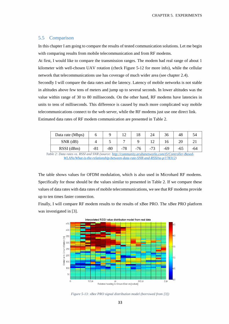
Finally, I will compare RF modem results to the results of xBee PRO. The xBee PRO platform
was investigated in [3].
Figure 5-13: xBee PRO signal distribution model (borrowed from [3])
CHAPTER 6. CONCLUSIONS
34
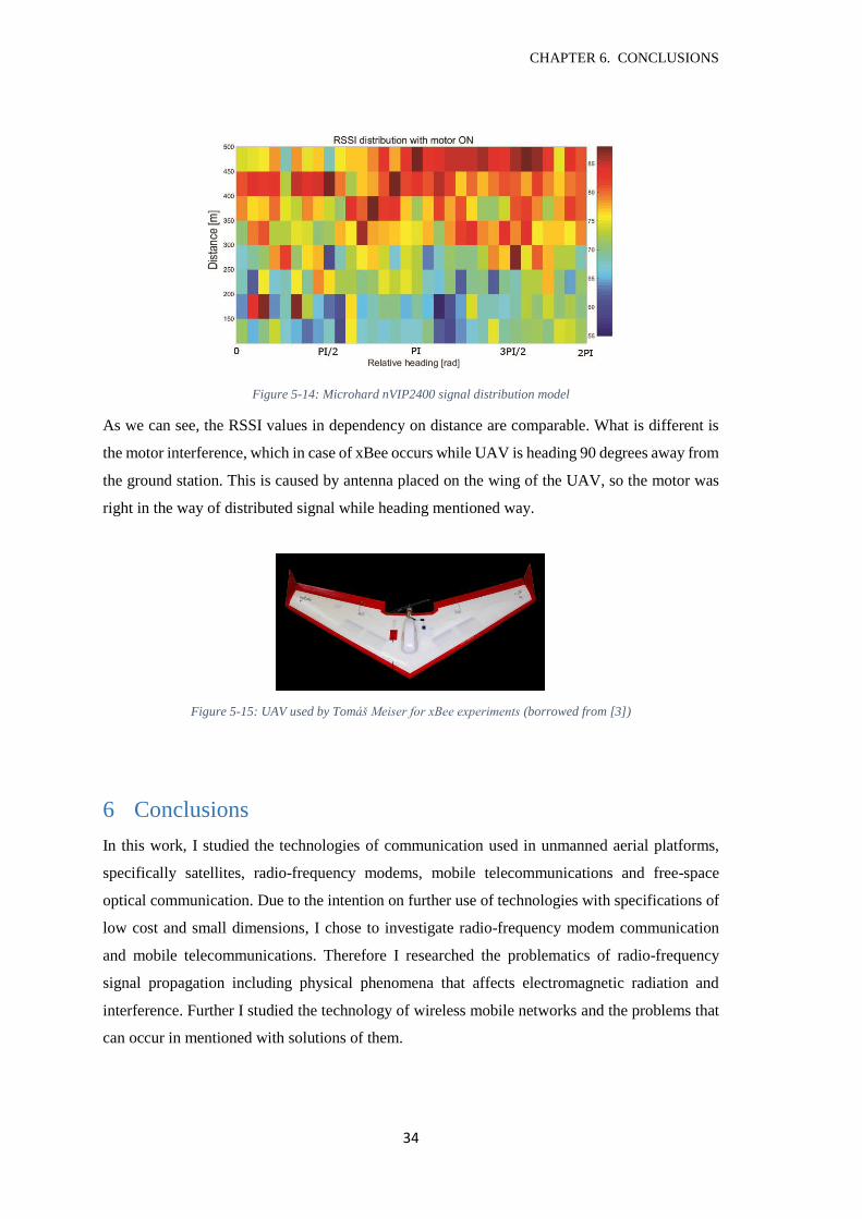
Figure 5-14: Microhard nVIP2400 signal distribution model
As we can see, the RSSI values in dependency on distance are comparable. What is different is
the motor interference, which in case of xBee occurs while UAV is heading 90 degrees away from
the ground station. This is caused by antenna placed on the wing of the UAV, so the motor was
right in the way of distributed signal while heading mentioned way.
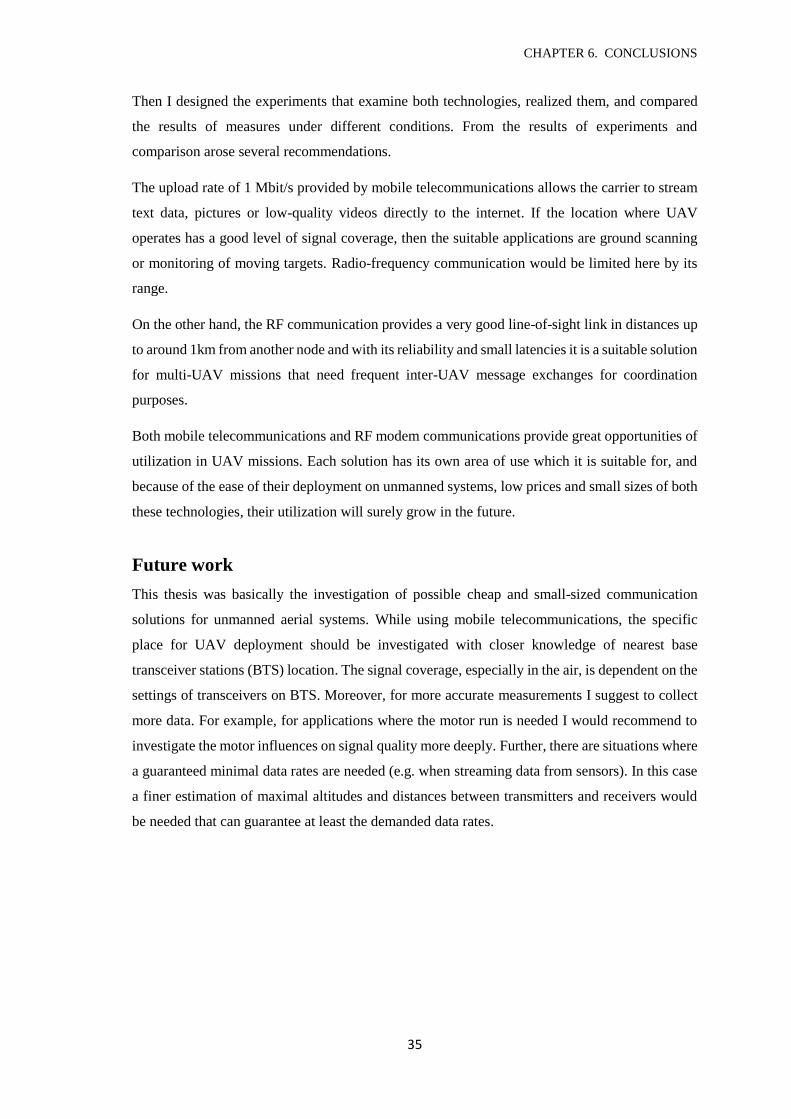
Figure 5-15: UAV used by Tomáš Meiser for xBee experiments (borrowed from [3])
6 Conclusions
In this work, I studied the technologies of communication used in unmanned aerial platforms,
specifically satellites, radio-frequency modems, mobile telecommunications and free-space
optical communication. Due to the intention on further use of technologies with specifications of
low cost and small dimensions, I chose to investigate radio-frequency modem communication
and mobile telecommunications. Therefore I researched the problematics of radio-frequency
signal propagation including physical phenomena that affects electromagnetic radiation and
interference. Further I studied the technology of wireless mobile networks and the problems that
can occur in mentioned with solutions of them.
CHAPTER 6. CONCLUSIONS
35
Then I designed the experiments that examine both technologies, realized them, and compared
the results of measures under different conditions. From the results of experiments and
comparison arose several recommendations.
The upload rate of 1 Mbit/s provided by mobile telecommunications allows the carrier to stream
text data, pictures or low-quality videos directly to the internet. If the location where UAV
operates has a good level of signal coverage, then the suitable applications are ground scanning
or monitoring of moving targets. Radio-frequency communication would be limited here by its
range.
On the other hand, the RF communication provides a very good line-of-sight link in distances up
to around 1km from another node and with its reliability and small latencies it is a suitable solution
for multi-UAV missions that need frequent inter-UAV message exchanges for coordination
purposes.
Both mobile telecommunications and RF modem communications provide great opportunities of
utilization in UAV missions. Each solution has its own area of use which it is suitable for, and
because of the ease of their deployment on unmanned systems, low prices and small sizes of both
these technologies, their utilization will surely grow in the future.
Future work
This thesis was basically the investigation of possible cheap and small-sized communication
solutions for unmanned aerial systems. While using mobile telecommunications, the specific
place for UAV deployment should be investigated with closer knowledge of nearest base
transceiver stations (BTS) location. The signal coverage, especially in the air, is dependent on the
settings of transceivers on BTS. Moreover, for more accurate measurements I suggest to collect
more data. For example, for applications where the motor run is needed I would recommend to
investigate the motor influences on signal quality more deeply. Further, there are situations where
a guaranteed minimal data rates are needed (e.g. when streaming data from sensors). In this case
a finer estimation of maximal altitudes and distances between transmitters and receivers would
be needed that can guarantee at least the demanded data rates.

CHAPTER 6. CONCLUSIONS
36
CHAPTER 7. BIBLIOGRAPHY
37
7 Bibliography
[1] Paolo Santi. Topology Control in Wireless Ad Hoc and Sensor Networks. Chichester,
West Sussex, England: John Wiley & Sons Ltd, 2005. ISBN 0-470-09453-2.
[2] Subir Kumar Sarkar, T. G. Basavaraju, and C. Puttamadappa. Ad Hoc Mobile Wireless
Networks: Principles, Protocols and Applications. CRC Press, 2007. ISBN 978-1-4665-
1446-1
[3] Tomáš Meiser. Distributed topology control in MANETs. Prague, 2012. Diploma thesis.
Czech Technical University in Prague, Faculty of Electrical Engineering.
[4] Toradex AG. Iris V1.1 Baseboat Datasheet. (September 2014).
[5] Toradex AG. Colibri T30 Datasheet. (December 2014).
[6] Digi International Inc. XBee®/XBee-PRO® RF Modules. (September 2009).
[7] Microhard Systems Inc. Nano VIP series Operating Manual.v1.23. (January 2014).
[8] Buckle Consulting. Unmanned Aircraft Systems.. Unmanned Aerial Vehicle Systems
[9] Association. [online]. 2015 [cit. May 2015]. Dostupné z: http://www.uavs.org/uas
[10] Ian Poole. Antennas, Aerials, & Propagation. Radio-Electronics.com: Resources and
analysis for electronic engineers. [online]. [cit. May 2015]. Available
at: http://www.radio-electronics.com/info/antennas/
[11] Ian Poole. EMI Electromagnetic Interference Basics. Radio-Electronics.com: Resources
and analysis for electronic engineers. [online]. [cit. May 2015]. Available
at: http://www.radio-electronics.com/info/circuits/emc-emi/electromagnetic-
interference-basics-tutorial.php
CHAPTER 7. BIBLIOGRAPHY
38
[12] Ian Poole. Electromagnetic waves – reflection, refraction, diffraction. Radio-
Electronics.com: Resources and analysis for electronic engineers. [online]. [cit. May
2015]. Available at: http://www.radio-
electronics.com/info/propagation/em_waves/electromagnetic-reflection-refraction-
diffraction.php
[13] Ian Poole. Radio propagation or radiowave propagation overview. Radio-
Electronics.com: Resources and analysis for electronic engineers. [online]. [cit. May
2015]. Available at: http://www.radio-electronics.com/info/propagation/radio-
propagation/radio-propagation-overview-tutorial.php
[14] Unmanned aerial vehicle. Wikipedia: The Free Encyclopedia. [online]. [cit. May 2015].
Available at: http://en.wikipedia.org/wiki/Unmanned_aerial_vehicle
[15] 2013/752/EU: Commission Implementing Decision of 11 December 2013 amending
Decision 2006/771/EC on harmonisation of the radio spectrum for use by short-range
devices and repealing Decision 2005/928/EC (notified under document C(2013) 8776)
Text with EEA relevance.
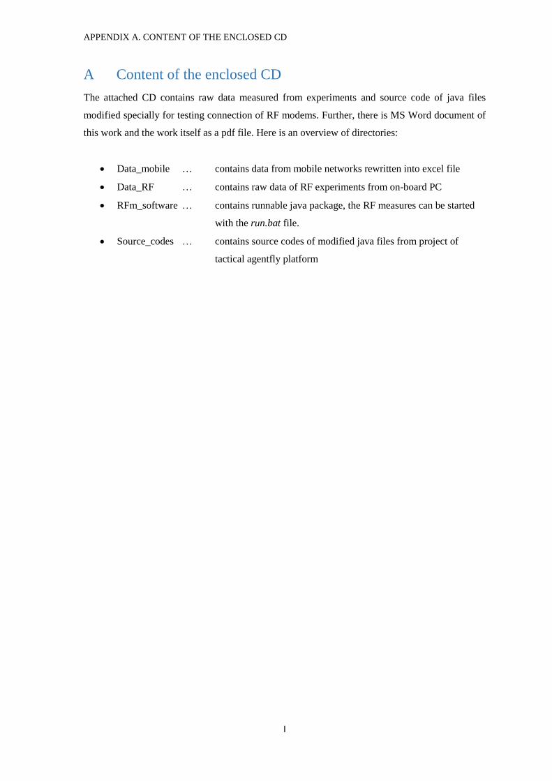
APPENDIX A. CONTENT OF THE ENCLOSED CD
I
A Content of the enclosed CD
The attached CD contains raw data measured from experiments and source code of java files
modified specially for testing connection of RF modems. Further, there is MS Word document of
this work and the work itself as a pdf file. Here is an overview of directories:
Data_mobile … contains data from mobile networks rewritten into excel file
Data_RF … contains raw data of RF experiments from on-board PC
RFm_software … contains runnable java package, the RF measures can be started
with the run.bat file.
Source_codes … contains source codes of modified java files from project of
tactical agentfly platform


![WINNER Presentation Templatewinner.ajou.ac.kr/publication/data/invited/20171129_NCW.pdf · Introduction UAV(Unmanned Aerial Vehicles) Definition [1] Aerial vehicles that do not carry](https://img.pdfslide.tips/doc/110x75/5fb329e00f7d963bb678cdb0/winner-presentation-introduction-uavunmanned-aerial-vehicles-definition-1-aerial.jpg)