Embed Size (px)
Citation preview
Design Patterns for Safety-CriticalEmbedded Systems
Von der Fakultät für Mathematik, Informatik undNaturwissenschaften der RWTH Aachen University
zur Erlangung des akademischen Grades einesDoktors der Ingenieurwissenschaften genehmigte Dissertation
vorgelegt von
Ashraf Armoushaus
Awarta-Palästina
Berichter: Professor Dr.-Ing. Stefan KowalewskiProfessor Dr. Bernhard Rumpe
Tag der mündlichen Prüfung: 15.06.2010
Diese Dissertation ist auf den Internetseiten der Hochschulbibliothek online verfügbar.

Ashraf ArmoushLehrstuhl Informatik [email protected]
Abstract
Over the last few years, embedded systems have been increasingly used in safety-critical applications where failure can have serious consequences. The designof these systems is a complex process, which is requiring the integration ofcommon design methods both in hardware and software to fulfill functional andnon-functional requirements for these safety-critical applications.Design patterns, which give abstract solutions to commonly recurring design
problems, have been widely used in the software and hardware domain. Inthis thesis, the concept of design patterns is adopted in the design of safety-critical embedded system. A catalog of design patterns was constructed tosupport the design of safety-critical embedded systems. This catalog includesa set of hardware and software design patterns which cover common designproblems such as handling of random and systematic faults, safety monitoring,and sequence control. Furthermore, the catalog provides a decision supportcomponent that supports the decision process of choosing a suitable pattern fora particular problem based on the available resources and the requirements ofthe applicable patterns.As non-functional requirements are an important aspect in the design of
safety-critical embedded systems, this work focuses on the integration of im-plications on non-functional properties in the existing design pattern concept.A pattern representation is proposed for safety-critical embedded applicationdesign methods by including fields for the implications and side effects of therepresented design pattern on the non-functional requirements of the systems.The considered requirements include safety, reliability, modifiability, cost, andexecution time.Safety and reliability represent the main non-functional requirements that
should be provided in the design of safety-critical applications. Thus, reliabilityand safety assessment methods are proposed to show the relative safety andreliability improvement which can be achieved when using the design patternsunder consideration. Moreover, a Monte Carlo based simulation method is usedto illustrate the proposed assessment method which allows comparing differentdesign patterns with respect to their impact on safety and reliability.
i

ii
Acknowledgments
I would like to express my sincere gratitude to my advisor, Prof. Dr.-Ing. StefanKowalewski for his considerable guidance, helpful advices, valuable information,and constant support during the development of this thesis.I would also like to thank Prof. Dr. Bernhard Rumpe for accepting to be a
co-referee of my doctorate thesis and his interest in my work. My thanks alsogo to the committee members, Prof. Dr. Peter Rossmanith, Prof. Dr. UlrikeMeyer, and Prof. Dr. Berthold Vöcking for their time and effort.I would like to acknowledge the German Academic Exchange Service (DAAD)
for granting me the PhD scholarship.I would also like to express my deepest thanks to Dr. Falk Salewski for his
suggestions, useful hints, and helpful advices during the first phase of my work.Many thanks go to all my colleagues at the Embedded Software Laboratory
at RWTH Aachen University, in particular John. F. Schommer, for providinga fruitful working atmosphere. Furthermore, I thank my student AlexanderGrinin for helping me to implement the catalog program.Last but not least, I am thankful and very appreciative to my wonderful
wife and my family for their love, encouragement and support during the entireperiod of my study.
Ashraf ArmoushAachen, June 2010
iii

iv
Contents
1. Introduction 11.1. Objectives . . . . . . . . . . . . . . . . . . . . . . . . . . . . . . . 21.2. Contributions . . . . . . . . . . . . . . . . . . . . . . . . . . . . . 31.3. Thesis Structure . . . . . . . . . . . . . . . . . . . . . . . . . . . 41.4. Bibliographic Notes . . . . . . . . . . . . . . . . . . . . . . . . . . 4
2. Preliminaries 52.1. Embedded Systems . . . . . . . . . . . . . . . . . . . . . . . . . . 52.2. Characteristics of Embedded Systems . . . . . . . . . . . . . . . . 62.3. Safety-Critical Systems . . . . . . . . . . . . . . . . . . . . . . . . 82.4. Concept of Design Patterns . . . . . . . . . . . . . . . . . . . . . 102.5. A Brief History of Design Patterns . . . . . . . . . . . . . . . . . 10
3. Pattern Representations 133.1. Traditional Pattern Representation . . . . . . . . . . . . . . . . . 133.2. Other Representations . . . . . . . . . . . . . . . . . . . . . . . . 143.3. Motivations for a New Representation . . . . . . . . . . . . . . . 143.4. Design Pattern Template . . . . . . . . . . . . . . . . . . . . . . . 163.5. Related Work . . . . . . . . . . . . . . . . . . . . . . . . . . . . . 18
3.5.1. Patterns for Safety-Critical Systems . . . . . . . . . . . . 193.5.2. Non-Functional Requirements in Design Patterns . . . . . 19
4. Safety and Reliability Assessment 214.1. Reliability Assessment . . . . . . . . . . . . . . . . . . . . . . . . 21
4.1.1. Limitations . . . . . . . . . . . . . . . . . . . . . . . . . . 224.1.2. Basic System . . . . . . . . . . . . . . . . . . . . . . . . . 224.1.3. Relative Reliability Improvement . . . . . . . . . . . . . . 22
4.2. Safety Standards . . . . . . . . . . . . . . . . . . . . . . . . . . . 234.2.1. IEC 61508 . . . . . . . . . . . . . . . . . . . . . . . . . . . 234.2.2. MIL-STD-882D . . . . . . . . . . . . . . . . . . . . . . . . 244.2.3. ISO 26262 . . . . . . . . . . . . . . . . . . . . . . . . . . . 244.2.4. DO-178B and DO-254 . . . . . . . . . . . . . . . . . . . . 244.2.5. Choice of standard for our work . . . . . . . . . . . . . . . 24
4.3. Safety and Risk Metrics . . . . . . . . . . . . . . . . . . . . . . . 25
v
Contents
4.4. Safety Integrity Levels . . . . . . . . . . . . . . . . . . . . . . . . 254.5. Safety Assessment . . . . . . . . . . . . . . . . . . . . . . . . . . 26
4.5.1. Applicability to Safety Integrity Levels . . . . . . . . . . . 274.5.2. Relative Safety Improvement . . . . . . . . . . . . . . . . 29
5. A Case Study: Software Diversity 315.1. Concept of Diversity Programming . . . . . . . . . . . . . . . . . 315.2. Acceptance Test . . . . . . . . . . . . . . . . . . . . . . . . . . . 325.3. The Quality of the Acceptance Test . . . . . . . . . . . . . . . . . 335.4. Recovery Block with Backup Voting . . . . . . . . . . . . . . . . 345.5. Simulation . . . . . . . . . . . . . . . . . . . . . . . . . . . . . . . 36
5.5.1. Architecture . . . . . . . . . . . . . . . . . . . . . . . . . . 365.5.2. Simulation Procedure . . . . . . . . . . . . . . . . . . . . 375.5.3. Notations and Assumptions . . . . . . . . . . . . . . . . . 38
5.6. Reliability Assessment . . . . . . . . . . . . . . . . . . . . . . . . 385.6.1. The effect of the “Probability of Failure” in a version . . . 395.6.2. The effect of the false negative cases in the acceptance test 415.6.3. The effect of the false positive cases in the acceptance test 42
5.7. Safety Assessment . . . . . . . . . . . . . . . . . . . . . . . . . . 425.7.1. The effect of the “Probability of Failure” in a version . . . 425.7.2. The effect of the false negative cases in the acceptance test 435.7.3. The effect of the false positive cases in the acceptance test 44
5.8. Summary . . . . . . . . . . . . . . . . . . . . . . . . . . . . . . . 44
6. Catalog of Design Patterns 476.1. Features . . . . . . . . . . . . . . . . . . . . . . . . . . . . . . . . 476.2. Architecture . . . . . . . . . . . . . . . . . . . . . . . . . . . . . . 486.3. Data Model . . . . . . . . . . . . . . . . . . . . . . . . . . . . . . 506.4. Application Guidelines . . . . . . . . . . . . . . . . . . . . . . . . 526.5. Decision Support . . . . . . . . . . . . . . . . . . . . . . . . . . . 53
6.5.1. Design Solutions . . . . . . . . . . . . . . . . . . . . . . . 536.5.2. Design Problems . . . . . . . . . . . . . . . . . . . . . . . 546.5.3. Decision Trees . . . . . . . . . . . . . . . . . . . . . . . . 54
6.6. Implementation . . . . . . . . . . . . . . . . . . . . . . . . . . . . 576.7. General Pattern . . . . . . . . . . . . . . . . . . . . . . . . . . . . 586.8. Catalog Structure . . . . . . . . . . . . . . . . . . . . . . . . . . . 59
7. Hardware Patterns 617.1. Notations . . . . . . . . . . . . . . . . . . . . . . . . . . . . . . . 617.2. Redundancy Notes . . . . . . . . . . . . . . . . . . . . . . . . . . 617.3. Homogeneous Duplex Pattern (HmD) . . . . . . . . . . . . . . . 62
vi
Contents
7.4. Heterogeneous Duplex Pattern (HtD) . . . . . . . . . . . . . . . . 697.5. Triple Modular Redundancy Pattern (TMR) . . . . . . . . . . . . 767.6. M-Out-Of-N Pattern (M-oo-N) . . . . . . . . . . . . . . . . . . . 817.7. Monitor-Actuator Pattern (MA) . . . . . . . . . . . . . . . . . . 867.8. Sanity Check Pattern (SC) . . . . . . . . . . . . . . . . . . . . . 927.9. Watchdog Pattern (WD) . . . . . . . . . . . . . . . . . . . . . . . 987.10. Safety Executive Pattern (SE) . . . . . . . . . . . . . . . . . . . . 103
8. Software Patterns 1098.1. Notations . . . . . . . . . . . . . . . . . . . . . . . . . . . . . . . 1098.2. Implementation Issues for Software Diversity . . . . . . . . . . . 1098.3. Assumptions . . . . . . . . . . . . . . . . . . . . . . . . . . . . . 1108.4. Voting Techniques . . . . . . . . . . . . . . . . . . . . . . . . . . 1108.5. N-Version Programming Pattern (NVP) . . . . . . . . . . . . . . 1118.6. Recovery Block Pattern (RB) . . . . . . . . . . . . . . . . . . . . 1178.7. Acceptance Voting Pattern (AV) . . . . . . . . . . . . . . . . . . 1258.8. N-Self Checking Programming Pattern (NSCP) . . . . . . . . . . 1328.9. Recovery Block with Backup Voting Pattern (RBBV) . . . . . . . 140
9. Combination of Hardware and Software Patterns 1499.1. Protected Single Channel Pattern (PSC) . . . . . . . . . . . . . . 1499.2. 3-Level Safety Monitoring Pattern (3-LSM) . . . . . . . . . . . . 154
10.Conclusion 16110.1. Summary . . . . . . . . . . . . . . . . . . . . . . . . . . . . . . . 16110.2. Future Work . . . . . . . . . . . . . . . . . . . . . . . . . . . . . 163
A. Decision Trees 165
Bibliography 171
vii

Contents
viii

List of Tables
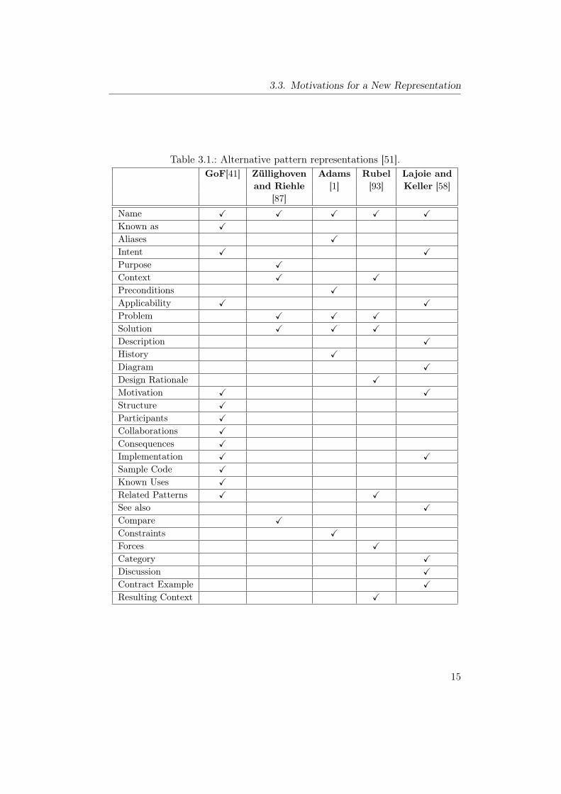
3.1. Alternative pattern representations [51]. . . . . . . . . . . . . . . 15
4.1. Safety recommendations in IEC 61508. . . . . . . . . . . . . . . . 274.2. Proposed system of recommendations for design patterns. . . . . 28
7.1. Notations for hardware patterns. . . . . . . . . . . . . . . . . . . 617.2. Recommendations for safety integrity levels. . . . . . . . . . . . . 657.3. Recommendations of HmD Pattern for safety integrity levels. . . 657.4. Recommendations for safety integrity levels. . . . . . . . . . . . . 737.5. Recommendations of HtD Pattern for safety integrity levels. . . . 737.6. Recommendations for safety integrity levels. . . . . . . . . . . . . 787.7. Recommendations of TMR Pattern for safety integrity levels. . . 787.8. Recommendations for safety integrity levels. . . . . . . . . . . . . 837.9. Recommendations of M-oo-N Pattern for safety integrity levels. . 837.10. Recommendations for safety integrity levels. . . . . . . . . . . . . 887.11. Recommendations of MA Pattern for safety integrity levels. . . . 897.12. Recommendations for safety integrity levels. . . . . . . . . . . . . 957.13. Recommendations of SC Pattern for safety integrity levels. . . . . 957.14. Recommendations of WD Pattern for safety integrity levels. . . . 1007.15. Recommendations for safety integrity levels. . . . . . . . . . . . . 1067.16. Recommendations of SE Pattern for safety integrity levels. . . . . 107
8.1. Notations for software patterns. . . . . . . . . . . . . . . . . . . . 1098.2. Recommendations for safety integrity levels. . . . . . . . . . . . . 1138.3. Recommendations of NVP Pattern for safety integrity levels. . . . 1138.4. Recommendations for safety integrity levels. . . . . . . . . . . . . 1218.5. Recommendations of RB Pattern for safety integrity levels. . . . 1218.6. Recommendations for safety integrity levels. . . . . . . . . . . . . 1288.7. Recommendations of AV Pattern for safety integrity levels. . . . . 1298.8. Recommendations for safety integrity levels. . . . . . . . . . . . . 1358.9. Recommendations of NSCP Pattern for safety integrity levels. . . 1368.10. Recommendations for safety integrity levels. . . . . . . . . . . . . 1458.11. Recommendations of RBBV Pattern for safety integrity levels. . . 145
ix
List of Tables
9.1. Recommendations of PSC Pattern for safety integrity levels. . . . 1519.2. Recommendations for safety integrity levels. . . . . . . . . . . . . 1579.3. Recommendations of 3-LSM Pattern for safety integrity levels. . . 157
x
List of Figures
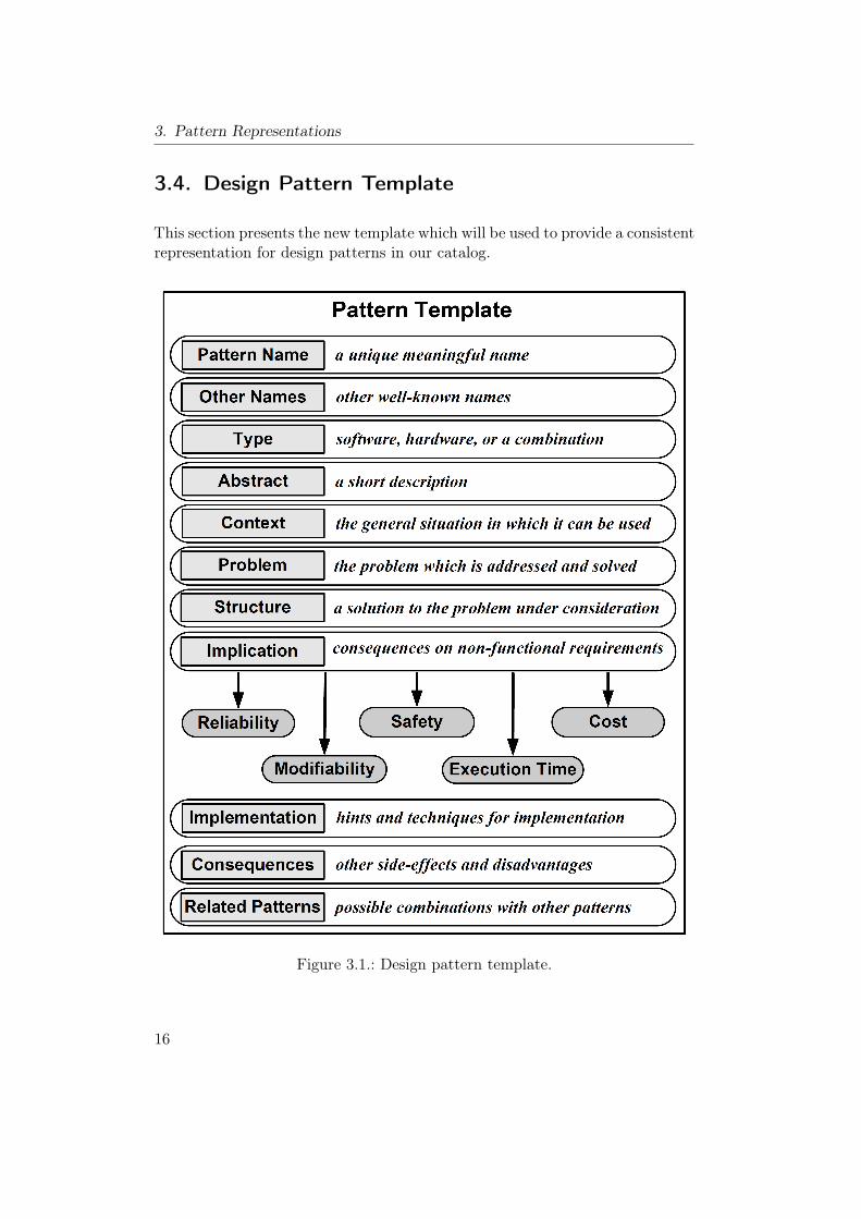
3.1. Design pattern template. . . . . . . . . . . . . . . . . . . . . . . . 16
4.1. Basic system without specific safety requirements. . . . . . . . . . 22
5.1. Relationship between the outcome of a version and acceptancetest. . . . . . . . . . . . . . . . . . . . . . . . . . . . . . . . . . . 33
5.2. Recovery block with backup voting method. . . . . . . . . . . . . 355.3. The architecture of safety and reliability simulator. . . . . . . . . 365.4. Reliability improvement in RBBV. . . . . . . . . . . . . . . . . . 395.5. The effect of the “Probability of Failure” in a single version on
RRI. . . . . . . . . . . . . . . . . . . . . . . . . . . . . . . . . . . 405.6. The effect of the probability of false negative cases in AT on RRI. 415.7. The effect of the probability of false postive cases in AT on RRI. 415.8. The effect of the “Probability of Failure” in a single version on RSI. 435.9. The effect of the probability of false negative cases in AT on RSI. 445.10. The effect of the probability of false positive cases in AT on RSI. 44
6.1. The architecture of the catalog software. . . . . . . . . . . . . . . 486.2. The entity-relationship model for the database. . . . . . . . . . . 516.3. The decision tree for the safety monitoring problem. . . . . . . . 556.4. Graphical user interface of the simulator module. . . . . . . . . . 576.5. Graphical user interface of the search wizard module. . . . . . . . 586.6. The general pattern. . . . . . . . . . . . . . . . . . . . . . . . . . 58
7.1. Homogeneous Duplex Pattern . . . . . . . . . . . . . . . . . . . . 637.2. Reliability modeling for HmD Pattern. . . . . . . . . . . . . . . . 657.3. Heterogeneous Duplex Pattern . . . . . . . . . . . . . . . . . . . 707.4. Reliability modeling for HtD Pattern. . . . . . . . . . . . . . . . 727.5. Triple Modular Redundancy Pattern . . . . . . . . . . . . . . . . 777.6. M-out-of-N Redundancy Pattern . . . . . . . . . . . . . . . . . . 827.7. Monitor-Actuator Pattern . . . . . . . . . . . . . . . . . . . . . . 877.8. Sanity Check Pattern . . . . . . . . . . . . . . . . . . . . . . . . . 937.9. Watchdog Pattern . . . . . . . . . . . . . . . . . . . . . . . . . . 997.10. Safety Executive Pattern . . . . . . . . . . . . . . . . . . . . . . . 104
xi
List of Figures
8.1. N-Version Programming Pattern . . . . . . . . . . . . . . . . . . 1128.2. Recovery Block Pattern . . . . . . . . . . . . . . . . . . . . . . . 1188.3. Acceptance Voting Pattern . . . . . . . . . . . . . . . . . . . . . 1268.4. N-Self Checking Programming Pattern . . . . . . . . . . . . . . . 1338.5. Recovery Block with Backup Voting Pattern . . . . . . . . . . . . 141
9.1. Protected Single Channel Pattern. . . . . . . . . . . . . . . . . . 1509.2. 3-Level Safety Monitoring Pattern . . . . . . . . . . . . . . . . . 155
A.1. The decision tree for the safety monitoring problem. . . . . . . . 165A.2. The decision tree for the general design problem (Part 1). . . . . 166A.3. The decision tree for the general design problem (Part 2). . . . . 167A.4. The decision tree for the hardware random faults problem. . . . . 168A.5. The decision tree for the hardware systematic faults problem. . . 169A.6. The decision tree for the sequence monitoring problem. . . . . . . 169A.7. The decision tree for the software faults problem. . . . . . . . . . 170
xii

List of Abbreviations
3-LSM . . . . . . . . 3-Level Safety MonitoringADC . . . . . . . . . Analog to Digital ConverterASIC . . . . . . . . . Application-Specific Integrated CircuitsASIL . . . . . . . . . Automotive Safety Integrity LevelAT . . . . . . . . . . . Acceptance TestAV . . . . . . . . . . . Acceptance VotingBIT . . . . . . . . . . Built-In TestCPLD . . . . . . . . Complex Programmable Logical DevicesCRC . . . . . . . . . Cyclic Redundancy CheckCV . . . . . . . . . . . Consensus VotingDSP . . . . . . . . . . Digital Signal ProcessorERM . . . . . . . . . Entity-Relationship ModelFN . . . . . . . . . . . False NegativeFP . . . . . . . . . . . False PositiveFPGA . . . . . . . . Field Programmable Gate ArrayFR . . . . . . . . . . . Functional RequirementGUI . . . . . . . . . . Graphical User InterfaceHmD . . . . . . . . . Homogeneous DuplexHtD . . . . . . . . . . Heterogeneous DuplexHW . . . . . . . . . . HardwareIEC . . . . . . . . . . International Electrotechnical CommissionM-oo-N . . . . . . . M-Out-Of-NMA . . . . . . . . . . . Monitor-ActuatorMISRA . . . . . . . Motor Industry Software Reliability AssociationMLV . . . . . . . . . Maximum Likelihood VotingMTBF . . . . . . . . Mean-Time Between FailuresMTTUF . . . . . . Mean Time to Unsafe FailureNFR . . . . . . . . . . Non-Functional RequirementNSCP . . . . . . . . N-Self Checking ProgrammingNVP . . . . . . . . . N-Version ProgrammingOOPSLA . . . . . Object-Oriented Programming Systems, Languages, and Ap-
plicationsPSF . . . . . . . . . Probability of Safe FailurePUF . . . . . . . . . Probability of Unsafe Failure
xiii
List of Abbreviations
PLoP . . . . . . . . . Pattern Languages of ProgramsPOST . . . . . . . . Power-On Self TestPSC . . . . . . . . . . Protected Single ChannelPV . . . . . . . . . . . Plurality VotingR . . . . . . . . . . . . . ReliabilityRB . . . . . . . . . . . Recovery BlockRBBV . . . . . . . . Recovery Block with Backup VotingRRI . . . . . . . . . . Relative Reliability ImprovementRSI . . . . . . . . . . . Relative Safety ImprovementSSS . . . . . . . . . . . Steady-State SafetySC . . . . . . . . . . . Sanity CheckSE . . . . . . . . . . . . Safety ExecutiveSIG . . . . . . . . . . . Soft-Goal Interdependency GraphSIL . . . . . . . . . . . Safety Integrity LevelSW . . . . . . . . . . . SoftwareTMR . . . . . . . . . Triple Modular RedundancyTN . . . . . . . . . . . True NegativeTP . . . . . . . . . . . True PositiveWD . . . . . . . . . . Watchdog
xiv

1. Introduction
Embedded systems are frequently used in a wide variety of applications to realizethe control part. These applications range from small applications like mobilephones, or microwave ovens, to complex and critical applications like railways,aerospace, or automotive systems. The common characteristic of embeddedsystems is that they contain combinations of hardware and software that arebuilt into other systems to perform dedicated functions.Embedded systems often have special functional and non-functional require-
ments somewhat different than those required for general-purpose computers.Thus, the hardware and software must be carefully designed with special de-sign techniques to make sure that the final design satisfies the functional andnon-functional requirements.Many embedded systems are described as “safety-critical ” due to the nature
of these applications which include considerable consequences of failures. Fail-ures in such systems could result in critical situations that may lead to seriousinjury, loss of life, or unacceptable damage to the environment. Therefore,safety and reliability often are more important issues in these applications thanperformance.The importance of embedded systems in safety-critical applications has been
growing continuously in the recent years. This increasing use introduces thedemand for successful, reusable, proven and tested designs that could speed upthe development process of new systems.The concept of design patterns is a universal approach to describe common
solutions to widely recurring design problems. A design pattern is an abstractrepresentation for how to solve a general design problem which occurs over andover in many applications. Describing proven solutions as design patterns pro-vides a good documentation for these solutions and makes them more accessiblefor future use in new systems.Since design patterns aim to support and help designers and system archi-
tects choose suitable solutions for design problems, this concept might also beapplicable and useful to support the design of safety-critical embedded systems.The adoption of this concept in the field of safety-critical systems must takeinto consideration the specific functional and the non-functional requirementsof these applications.While the current concept of design patterns has been addressed for many
1
1. Introduction
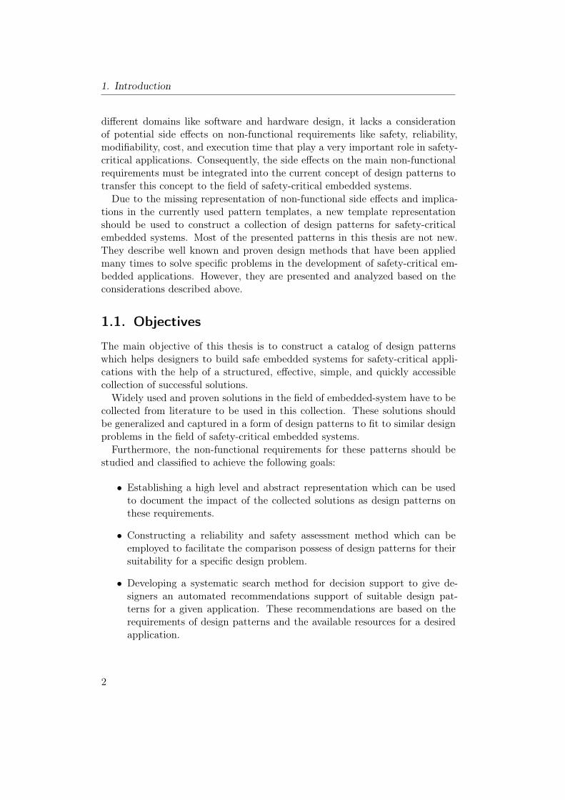
different domains like software and hardware design, it lacks a considerationof potential side effects on non-functional requirements like safety, reliability,modifiability, cost, and execution time that play a very important role in safety-critical applications. Consequently, the side effects on the main non-functionalrequirements must be integrated into the current concept of design patterns totransfer this concept to the field of safety-critical embedded systems.Due to the missing representation of non-functional side effects and implica-
tions in the currently used pattern templates, a new template representationshould be used to construct a collection of design patterns for safety-criticalembedded systems. Most of the presented patterns in this thesis are not new.They describe well known and proven design methods that have been appliedmany times to solve specific problems in the development of safety-critical em-bedded applications. However, they are presented and analyzed based on theconsiderations described above.
1.1. Objectives
The main objective of this thesis is to construct a catalog of design patternswhich helps designers to build safe embedded systems for safety-critical appli-cations with the help of a structured, effective, simple, and quickly accessiblecollection of successful solutions.Widely used and proven solutions in the field of embedded-system have to be
collected from literature to be used in this collection. These solutions shouldbe generalized and captured in a form of design patterns to fit to similar designproblems in the field of safety-critical embedded systems.Furthermore, the non-functional requirements for these patterns should be
studied and classified to achieve the following goals:
• Establishing a high level and abstract representation which can be usedto document the impact of the collected solutions as design patterns onthese requirements.
• Constructing a reliability and safety assessment method which can beemployed to facilitate the comparison possess of design patterns for theirsuitability for a specific design problem.
• Developing a systematic search method for decision support to give de-signers an automated recommendations support of suitable design pat-terns for a given application. These recommendations are based on therequirements of design patterns and the available resources for a desiredapplication.
2
1.2. Contributions
1.2. Contributions
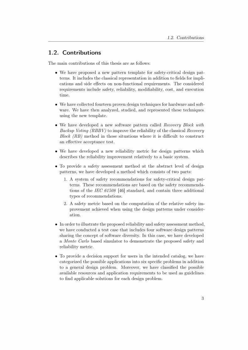
The main contributions of this thesis are as follows:
• We have proposed a new pattern template for safety-critical design pat-terns. It includes the classical representation in addition to fields for impli-cations and side effects on non-functional requirements. The consideredrequirements include safety, reliability, modifiability, cost, and executiontime.
• We have collected fourteen proven design techniques for hardware and soft-ware. We have then analyzed, studied, and represented these techniquesusing the new template.
• We have developed a new software pattern called Recovery Block withBackup Voting (RBBV) to improve the reliability of the classical RecoveryBlock (RB) method in those situations where it is difficult to constructan effective acceptance test.
• We have developed a new reliability metric for design patterns whichdescribes the reliability improvement relatively to a basic system.
• To provide a safety assessment method at the abstract level of designpatterns, we have developed a method which consists of two parts:
1. A system of safety recommendations for safety-critical design pat-terns. These recommendations are based on the safety recommenda-tions of the IEC 61508 [46] standard, and contain three additionaltypes of recommendations.
2. A safety metric based on the computation of the relative safety im-provement achieved when using the design patterns under consider-ation.
• In order to illustrate the proposed reliability and safety assessment method,we have conducted a test case that includes four software design patternssharing the concept of software diversity. In this case, we have developeda Monte Carlo based simulator to demonstrate the proposed safety andreliability metric.
• To provide a decision support for users in the intended catalog, we havecategorized the possible applications into six specific problems in additionto a general design problem. Moreover, we have classified the possibleavailable resources and application requirements to be used as guidelinesto find applicable solutions for each design problem.
3
1. Introduction
• We have constructed a data model to store the design patterns and theirrelated information. We have then implemented the catalog of design pat-tern which includes documentation for fifteen design patterns in additionto a user decision support as a desktop application.
1.3. Thesis Structure
The rest of this thesis is organized as follows: Chapter 2 gives a descriptionof preliminaries of this research, including embedded systems, safety-criticalsystems, functional and non-functional requirements, and the concept of designpatterns. Chapter 3 presents the classical representations for design patternsand the new proposed template.Chapter 4 describes safety and reliability assessment method proposed for
safety critical design patterns. Chapter 5 presents a case study, which demon-strates the use of the developed assessment method. It also contains the resultsof the conducted simulation for four design patterns.Chapter 6 describes the structure and basic features of the develop catalog
program. The main part of this thesis, which contains the documented designpatterns, is presented in Chapter 7 to 9.Finally, Chapter 10 summarizes this thesis and outlines possible issues for
future work.
1.4. Bibliographic Notes
Some parts of this thesis are based on work that has been previously presentedin earlier publications. The new pattern representation template with a com-parison to currently used classical representations was published in [6, 9]. Theeffect of a weak acceptance test on Recovery Block method and the basic ideaof the Recovery Block with Backup Voting as a fault-tolerant method was pub-lished in [7]. Later, the Recovery Block with Backup Voting was published asdesign pattern in [8]. Regarding the developed safety assessment method forsafety-critical design patterns, the safety metric was published in [4] while thesystem of safety recommendations was published in [5].
4
2. Preliminaries
This chapter provides some preliminaries for this thesis. The first two sectionsintroduce embedded and safety-critical systems. Section 2.4 presents the basicconcepts of design patterns, while Section 2.5 offers a brief literature review ofthe use of design patterns.
2.1. Embedded Systems
Nowadays, embedded systems are widely used in various applications and de-vices such as mobile phones, microwave ovens, cars, medical devices, aircrafts,telecommunications, trains, and power plants. The growing importance of em-bedded systems in many fields is largely driven by advances in microelectronicsand software.Unlike general-purpose computers, embedded systems are dedicated to per-
form application-specific functions. Such systems are designed to interact witha larger embedding system, where they should be enclosed or embedded, tosatisfy the requirements for an application. Usually, an embedded system in-cludes sensors and dedicated input devices to collect information about thesurrounding environment, and actuators to control that environment.While embedded systems are widely associated with microprocessors and
microcontrollers, embedded systems can contain a variety of other technolo-gies such as digital signal processors (DSPs), complex programmable logicaldevices (CPLDs), application-specific integrated circuits (ASICs), and field pro-grammable gate arrays (FPGAs). In embedded systems, the developed softwareis often dependent on the used hardware, and the design of the hardware andsoftware influence each other. Therefore, embedded hardware and software mustbe concurrently designed or the interface must be clearly defined [64, 99].Based on these aspects, there are many definitions for embedded systems (see
e.g. [99, 18, 74] ) but one of the most general definitions is: “Embedded systemsare information processing systems that are embedded into a larger enclosingproduct” [71].In the most general case, an embedded system consists of a combination of
hardware and software components that interact with the physical environmentthrough sensors and actuators to perform a dedicated task. Due to the tight
5
2. Preliminaries
relation between hardware and software in embedded systems, they should becarefully designed to make sure that implementation meet the main require-ments for the embedded system and also for the enclosing product.
2.2. Characteristics of Embedded Systems
Despite the variety of embedded systems applications and implementation meth-ods, there are some common characteristics in these systems that can be sum-marized as follows:
Dedicated Functionality
Since an embedded system is normally used to perform the control and infor-mation processing for the enclosing system, it accomplishes some predefinedtasks that are related to the given application. This is in contrast with general-purpose computers where it is more typical to run a large variety of applications.
Limited Resources
For many reasons (like nature of applications, marketing issues, productioncosts, or hardware technology), most of today’s embedded systems face strin-gent constraints in terms of limited resources such as memory size, hardwarefunctionality, input and output resources, clock frequency, power consumption,operating system, weight, size, and so forth.
Performance and Efficiency
Achieving high performance, which is most of the time characterized by theamount of work done and the execution time, is of great importance in manyembedded systems. Due to the constraints of limited resources, embedded sys-tems have to be also efficient in many aspects such as memory usage, powerconsumption, and hardware resources. In general, improved performance rep-resents a challenging optimization problem that involves several contradictoryrequirements. Therefore, designers of embedded systems must clearly under-stand the application and its associated constraints [77].
Real Time Constraints
Time in embedded systems is often one of the acute constraints that are notfound in typical computer systems. Most embedded systems have to react to ex-ternal events and perform computational tasks within precise timing constraintsdetermined by the environment. These systems, where the correctness depends
6
2.2. Characteristics of Embedded Systems
on the output results as well as on the time at which the results are produced,are classified as “Real-Time Systems”. (see e.g. [21, 24] for more classificationsand trends in real-time embedded systems).
Interaction with Environments
Commonly, embedded systems provide control and sensing to the enclosing sys-tems, thus they interact continuously with environments through sensors, trans-ducers, and actuators. In many cases, the interactions between an embeddedsystem and its environment are hidden from the user who just uses dedicatedinput devices or limited graphical user interfaces.
Dependability
Dependability1 is defined in [14, 15] as: “the ability of system to avoid failuresthat are more frequent or more severe, and outage durations that are longer,than is acceptable to the user(s)”. Therefore, the term dependability as a systemproperty is highly related to the safety-critical applications or to the applicationsthat involve direct impact on the environment or on the users. As more andmore embedded systems are deployed in our daily life, designers should ensurethat these systems are dependable.The notion of dependability as presented in [15] covers a list of attributes
which includes:
• Availability : readiness for correct service.
• Reliability : continuity of correct service.
• Safety : absence of catastrophic consequences on the user(s) and the en-vironment.
• Integrity : absence of improper system alterations.
• Maintainability : ability to undergo modifications and repairs.
In this thesis, we will mainly focus on the safety and reliability as major non-functional requirements for safety-critical embedded system, which does notimply that the other attributes are less important. Further information aboutthe other attributes can be found in [62, 97, 14, 15].
1The various dependability concepts, which are used throughout this thesis to describe as-pects of safety-critical systems, like dependability, reliability, safety, availability, fault,failure, error, fault detection, fault masking, fault tolerance, fault removal, and fault pre-vention, are compliant with the taxonomy and basic concepts presented in [15].
7
2. Preliminaries
2.3. Safety-Critical Systems
The definition of safety-critical system can be derived from the definition ofsafety which is: “a property of a system that it will not endanger human lifeor the environment” [97]. Therefore, the “Safety-Critical Systems” is used todescribe those systems or applications in which failure can lead to serious injury,loss of life, significant property damage, or damage to the environment [54, 38,39].Based on this definition, there are many fields that can be classified as safety-
critical such as medical care devices, nuclear plants, railways, weapons, automo-tive industry, and aircrafts. The design of these systems is considered to be acomplex process, which involves the integration of well-known design strategiesand techniques in hardware and software to fulfill two types of requirements:
• Functional Requirements (FRs): the functions to be performed, orwhat an embedded system is expected to do.
• Non-Functional Requirements (NFRs): the quality attributes of asystem as it performs its job [90]. Moreover, they include evolution qual-ities, which have to be provided in a system, such as modifiability andcost.
The functional requirements are clearly important for any computer system,but in the field of safety-critical systems, the non-functional requirements arealso of great importance to be provided in the final system. The non-functionalrequirements for safety-critical systems include a set of requirements like highreliability, safety, availability, ease maintainability, low cost, and small size.While the relative impotence of these requirements varies from one applicationto another, all safety-critical systems must guarantee an adequate level of safety.Ensuring safety in the design of a safety-critical embedded involves a lot of
analysis and testing. Since safety property is determined by the possible fail-ures that can lead to a hazardous situation, one of the mostly used techniques ishazard2 analysis which is at the heart of any safety-critical system [66]. Hazardanalysis is an iterative method that is carried out throughout all the develop-ment phases with purpose to: identify the unsafe states, evaluate the risk of thehazards, and to identify the necessary measures that can be taken to deal withthese hazards [47].System safety consists of two parts, hardware safety and software safety. Dif-
ferent techniques are normally used to reduce hazards and enhance safety inthe two parts. In hardware, redundancy and diversity are the most common
2Hazard: “is a situation in which there is actual or potential danger to people or to theenvironment” [97].
8
2.3. Safety-Critical Systems
techniques, while in software the techniques includes design diversity, hazardsprevention, hazard detection, or controlling hazards when they occur [67]. More-over, designers of software and hardware for a safety-critical embedded systemmust ensure the safe integration of the two parts to guarantee the safe operationof this system.Generally, failures in safety-critical systems are the results of errors which are
in turn the results of faults. Therefore, the general techniques that are usedto successfully attain dependability (which includes safety) can be also used toenhance system safety. These techniques can be categorized according to thestage in which the technique is performed (see e.g. [81, 15]):
• Fault Avoidance or Prevention: how to avoid or prevent occurrenceof faults. These techniques are conducted during system development toreduce the number of introduced faults.
• Fault Removal: how to reduce the number of faults. This is the secondstep, and includes testing and inspection.
• Fault Tolerance: how to prevent system failures from occurring. Thefault tolerance techniques are employed during the development time toenable the system to tolerate remaining faults and to deliver correct ser-vice in the presence of faults.
• Fault Forecasting: how to provide system evaluation, via estimating thepresent number, the future incident and consequences of faults. Thesetechniques are used to assess the fault tolerance robustness.
It is important to note that fault prevention, removal and tolerance shouldnot be regarded as alternatives [83], but rather they should be considered ascomplementary techniques. The degree of success of an effective combinationof these techniques can be evaluated with fault forecasting techniquesFinally, safety considerations must be taken into account throughout the
entire development process of safety-critical embedded systems. Furthermore, itis necessary to provide an appropriate and unified system of judgment to reflectthe importance of safe and correct operations in the target applications. Thus,many safety standards have been developed to cover the safety management ofsafety-critical systems throughout their lifecycles. Some of the important andcommonly used standards are: MIL-STD-882D [35] which is a military standardand IEC61508 [46] which is a well-known application-independent standard.Further information about safety standards will be presented in Chapter 4.
9
2. Preliminaries
2.4. Concept of Design Patterns
The concept of design patterns became one of the widely used and universal ap-proaches for describing and documenting recurring solutions for design problems.The idea of design patterns was original proposed by the architect ChristopherAlexander [2] who wrote several books on the field of urban planning and build-ing construction. He defined a design pattern as a construct that expressesa relation between three parts: context, problem and solution(what is calledthree-part rule). Ever since, this concept has been applied to many differentdomains including hardware and software design.In software domain, design patterns became popular in software architec-
ture and development after the success of the book Design Patterns: Elementof Reusable Object-Oriented Software by Erich Gamma, Richard Helm, RalphJohnson and John Vlissides [41] frequently referred to as the Gang of Four(GoF). They defined a design pattern as Description of communicating objectsand classes that are customized to solve a general design problem in a particularcontext. This book, which includes a collection of patterns for object-orientedsoftware design, was not the first effort to use the concept of design patternin software; however, it is considered as the foundation for design patterns insoftware construction.Like in software development, design patterns have been also adapted for
hardware design to provide implementation-independent and abstract views forrecurring hardware design solutions. The more general benefit of using designpattern is to improve the hardware development process through importing theadvantages of object oriented modeling techniques (see e.g. [31, 32, 88, 102]).In general, we can summarize a design pattern as an abstract representation
for how to solve a general design problem that occurs over and over in manyapplications. The main purpose of design patterns is to support and help de-signers and system architects choose a suitable solution for a recurring designproblem among available collection of successful solutions. Moreover, designpatterns can simplify communication between practitioners and provide a goodway for documentation of proven design techniques.
2.5. A Brief History of Design Patterns
While the GoF book [41] has been the most popular work on design patternsover the last two decades, there have been several attempts in the literature toadapt this concept in many fields of system design. In 1987 Cunningham andBeck presented five patterns for designing windows-based user interfaces withSmalltalk [16]. Around the same time, Jim Coplien began to document C++
10
2.5. A Brief History of Design Patterns
Idioms that represent specific constructs like patterns for C++. He publishedthese idioms as a book in 1991 [29], and later he published these idioms andpatterns as paper in 1997 [30].From 1990 to 1993, several pattern papers, which addressed the use of de-
sign pattern in object oriented programming, were published at the OOPSLA(Object-Oriented Programming Systems, Languages, and Applications) confer-ence. In 1994, the Hillside group (see http://hillside.net) organized the firstPLoP (Pattern Languages of Programs) annual conference. The revised papersfrom PLoP are normally published in the book series “Pattern Languages ofProgram Design” (see e.g. [69]). Meanwhile, Buschmann et al. published thebook “Pattern-oriented software architecture: a system of patterns” [23] whichincludes a collection of relatively independent solutions to common design prob-lems represented as a catalog of design patterns.Another well known work is the catalog presented by Bruce Douglass in [37].
This catalog includes a set of patterns for real-time embedded systems. Thepresented patterns deal with real-time design issues like concurrency, resourcesharing, distribution, and safe and reliable architecture.Finally, the concept of design pattern has become an important area of re-
search in many fields like: fault tolerance [45], telecommunications [89], embed-ded systems [78, 79], security [94, 103], and many other fields. Each of thesefields has its own patterns and sometime its own representation, but all followthe basic principle of design patterns.
11

2. Preliminaries
12
3. Pattern Representations
This chapter describes the advantages of including the side effects on non-functional requirements in the proposed pattern representation. The first sec-tion presents parts of the traditional pattern representation that are used in allpatterns. After that, we give an overview about other commonly used represen-tations. Section 3.3 gives the motivation for using a new template representa-tion. Next, we review the related work to our approach for safety-critical designpatterns and the non-functional requirements in Section 3.5. The last sectionpresents the template which is used in our catalog to represent design patterns.We published the general idea of the new template representation in two
papers [6, 9].
3.1. Traditional Pattern Representation
The pattern representation as proposed by Alexander was derived from thedefinition of design patterns. He defined a design pattern as a construct thatincludes a relation between three parts: context, problem, and solution. Thisthree-part rule indicates the general structure that should be provided in anypattern representation form.In generally, the traditional pattern representation consists of four essential
elements:
• Name : a meaningful name.
• Context : describes the preconditions or the general situation in whichthe pattern can be used to solve the problem.
• Problem : describes the problem which is addressed by the pattern.
• Solution : explains a solution to the problem under consideration.
This structure shows the basic relation between the main parts: the problemto be solved, the appropriate context that should be satisfied in order to applythe pattern, and the solution presented by the pattern. Moreover, the solutionmust be abstract and independent from specific implementation, which is oneof the main attractive issues in design patterns.
13
3. Pattern Representations
3.2. Other Representations
Based on Alexander’s traditional form of representation presented in the previ-ous section, several representation forms have been proposed and used to give ahighly structured and abstract description for design patterns. Tab. 3.1 showssome of the alternative representations defined by different authors for the de-scription of design patterns.While each form has been used to provide a uniform way of documentation
and communication between experts and practitioners in a specific field, thereis no uniform agreement between these forms on a single template. Some repre-sentation forms include precise and short structure, while others include morecomprehensive and expressive forms. In some cases, the authors chose differentnames to describe the same element: e.g. (Context, Applicability, and Precon-ditions) and (Intent, Motivation, and Purpose). Despite of diverse formats,names and domains, these representations should at least contain the essentialelements as defined by the traditional representation.
3.3. Motivations for a New Representation
As shown in Section 2.3, the non-functional requirements, which include thequality attributes of the system as it performs its tasks, are of great importancein safety-critical applications and should be considered during the developmentprocess of such systems. Furthermore, these non-functional requirements shouldbe represented and taken into consideration in the high-level representations ofdesign methods such as in design patterns.While the concept of design patterns has been extensively studied and used
in various fields of system design, it typically lacks a consideration of potentialconsequences and side effects on non-functional requirements. Some of the well-known representations (e.g. GoF ) initialize a field for consequences, but mostof the time this field deals with the impact of a design pattern on space, time,system’s flexibility, system’s portability, and other implementation issues [41].Nevertheless, none of the used forms includes the impact of a design patternon the non-functional requirement (safety, reliability, modifiability, cost, andexecution time) in its representation.The missed representation of the implication on these non-functional require-
ments in the currently used templates reveals the need for new template thatincludes a part for these requirements. This template will be used to achievethe main objective of this thesis which includes the construction of a catalog ofdesign patterns for safety-critical embedded systems.
14
3.3. Motivations for a New Representation
Table 3.1.: Alternative pattern representations [51].GoF[41] Züllighoven Adams Rubel Lajoie and
and Riehle [1] [93] Keller [58][87]
Name X X X X XKnown as XAliases XIntent X XPurpose XContext X XPreconditions XApplicability X XProblem X X XSolution X X XDescription XHistory XDiagram XDesign Rationale XMotivation X XStructure XParticipants XCollaborations XConsequences XImplementation X XSample Code XKnown Uses XRelated Patterns X XSee also XCompare XConstraints XForces XCategory XDiscussion XContract Example XResulting Context X
15
3. Pattern Representations
3.4. Design Pattern Template
This section presents the new template which will be used to provide a consistentrepresentation for design patterns in our catalog.
Figure 3.1.: Design pattern template.
16
3.4. Design Pattern Template
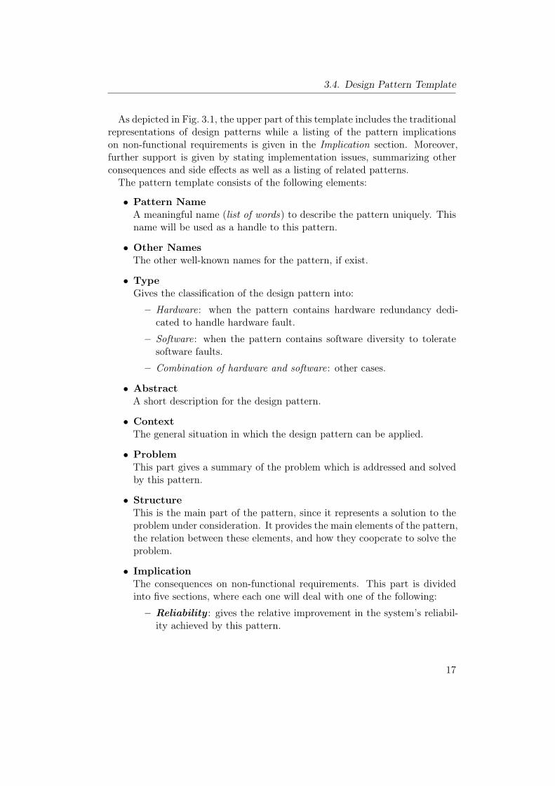
As depicted in Fig. 3.1, the upper part of this template includes the traditionalrepresentations of design patterns while a listing of the pattern implicationson non-functional requirements is given in the Implication section. Moreover,further support is given by stating implementation issues, summarizing otherconsequences and side effects as well as a listing of related patterns.The pattern template consists of the following elements:
• Pattern NameA meaningful name (list of words) to describe the pattern uniquely. Thisname will be used as a handle to this pattern.
• Other NamesThe other well-known names for the pattern, if exist.
• TypeGives the classification of the design pattern into:
– Hardware: when the pattern contains hardware redundancy dedi-cated to handle hardware fault.
– Software: when the pattern contains software diversity to toleratesoftware faults.
– Combination of hardware and software: other cases.
• AbstractA short description for the design pattern.
• ContextThe general situation in which the design pattern can be applied.
• ProblemThis part gives a summary of the problem which is addressed and solvedby this pattern.
• StructureThis is the main part of the pattern, since it represents a solution to theproblem under consideration. It provides the main elements of the pattern,the relation between these elements, and how they cooperate to solve theproblem.
• ImplicationThe consequences on non-functional requirements. This part is dividedinto five sections, where each one will deal with one of the following:
– Reliability : gives the relative improvement in the system’s reliabil-ity achieved by this pattern.
17

3. Pattern Representations
– Safety : gives the safety recommendations for the pattern in additionto the relative safety improvement that can be achieved.
– Cost : the implications on costs include:
1. The recurring cost per unit, which reflects the additional costsresulting from additional or specific hardware components re-quired by the design pattern.
2. The development cost for this pattern.
– Modifiability : describes the degree to which a system developedaccording to this design pattern can be modified and changed.
– Impact on execution time : with this implication, the effect ofthe pattern on the total time of execution at runtime is indicated. Itshows the execution time overhead that is resulting from the appli-cation of this pattern in the worst and average cases.
• ImplementationThis part gives the aspects, hints, and techniques that should be takeninto consideration when implementing the pattern.
• ConsequencesIncludes side-effects and disadvantages that may appear due to the appli-cation of this pattern.
• Related PatternsThe closely related design patterns to this pattern, and the possibility tocombine the related patterns with this one.
Chapter 4 gives more details about reliability and safety assessment methodswhich have been used in this thesis to show the implications of the design patternon safety and reliability.
3.5. Related Work
As the field of design pattern software is rapidly growing, many research havefocused on the use of design pattern in software domain [41, 23, 28, 16, 30].Nevertheless, further research is still needed in the domain of safety-critical em-bedded systems to integrate the non-functional requirements (basically safety)in design patterns.This section presents related work regarding design patterns for safety-critical
systems and the integration of non-functional requirements in design patterns.
18
3.5. Related Work
3.5.1. Patterns for Safety-Critical Systems
In the field of safety-critical patterns, the most popular work is in [36, 37]. BruceDouglass propose several design patterns for safety-critical systems based onwell known fault tolerant design methods and by integrating some modificationto increase the safety level on these patterns.A further work, which gives a way to construct software safety patterns, is
in [100]. Wu and Kelly present a method for software architecture design forsafety-related systems. This method is based upon extending the notation ofarchitectural tactics to include safety as a consideration. The architecture tac-tics are design decisions that aid designers in selecting appropriate techniquesto achieve quality attributes. Furthermore, related tactics can be combined intoa pattern that controls a specific quality attribute.
3.5.2. Non-Functional Requirements in Design Patterns
To establish a connection between the non-functional requirements and theconcept of design patterns, many research have been conducted in this context.Gross and Yu [43] discuss the relationship between non-functional requirementsand design patterns, and propose a systematic approach for evaluating designpatterns with respect to non-functional requirements. They propose the use ofdesign patterns for establishing traces between non-functional goals in a goaltree such as a soft goal interdependency graph (SIG) and the system design.Cleland-Huang et al. [27, 40] enhance the patterns defined by Gross and Yuin [43] through defining a model for establishing traceability between certaintypes of non-functional requirements and code artifacts, through the use of de-sign patterns as intermediary objects. Xu et al. [101] classify the dependabilityneeds into three types of requirements and proposed an architectural patternthat allows requirements engineers and architects to map dependability require-ments into three corresponding types of architectural components.Bitsch [20] gives a method to use a formal notation to specify the safety re-
quirement with the help of safety patterns. Later, Konrad et al. [55, 56] describea research of how the principle of design pattern can be applied to requirementsspecifications, which they term requirements patterns for embedded systems.They include a constraints field in the pattern template to show the functionaland non-functional restrictions that are applied to the system.In comparison to our work, none of the aforementioned approaches shows
clearly the implications on the non-functional requirements as part of the pat-tern. These patterns and the later developed patterns focused on the traditionalstructure of the pattern that includes: context, problem and solution. The useof non-functional requirements in these approaches is restricted to the require-
19
3. Pattern Representations
ment analysis phase of the design process, or as a constraint field in the template.Moreover, they do not give a relative measure or indication to the implicationof the pattern on non-functional requirements.
20
4. Safety and Reliability Assessment
This chapter presents in detail the implications of design pattern on safetyand reliability. The first section describes the idea of computing the relativereliability improvement. Section 4.2 gives a brief overview of safety standards.Section 4.3 shows the importance of safety and risk metrics and gives someexamples of common metrics. Section 4.4 describes the basic idea of safetyintegrity levels as presented in IEC 61508 standard. The last section presents asafety assessment method for design patterns. This method includes a system ofsafety recommendations for design patterns and a safety metric for the relativesafety improvement.We published the general idea of safety metric for design pattern in [4] and
the system of safety recommendations in [5].
4.1. Reliability Assessment
Reliability is conventionally defined as “a characteristic of an item, expressedby the probability that the item will perform its required function under givenconditions for stated time interval ” [19]. Based on this general definition, itrepresents an essential requirement for safety-critical systems, especially in thosesituations where it is difficult to reach a fail-safe state1. For example, in avionicsystems there is usually no state that can be considered to be fail-safe. Thus,such systems must continue operating correctly to assure safety.It is clear from the above definition that reliability of a safety-critical system
is totally related to probability of faults that could lead to system failure. Con-sequently, several fault-tolerance methods and techniques have been proposedand used to tolerate hardware and software faults which, in turn, lead to systemreliability improvement.The best-known measure for reliability is a mathematical measure R(t) which
gives the probability that the system is functioning correctly over the timeinterval [0, t] [57]. The increase in this measure, which is achieved after using aspecific design technique, can be used to express the improvement in reliability.
1Fail-Safe State: a state which, in the event of failure, can be identified as being safewithout risk.
21
4. Safety and Reliability Assessment
4.1.1. Limitations
A design pattern represents a high level abstract solution to a commonly recur-ring design problem. It is not related to a specific application or to a specificimplementation; thus, it is very difficult to find an actual value for probabilitythat the system has been up continuously and without failures after applyingthe pattern under consideration.
4.1.2. Basic System
The main objective of the implication part in the pattern template is to givean indication about side-effects on non-functional requirement after using thedesign pattern under consideration. This part will be devoted to make anassessment and compression between different applicable patterns for a specificdesign problem.As a result to the previous limitations, instead of giving an actual value for
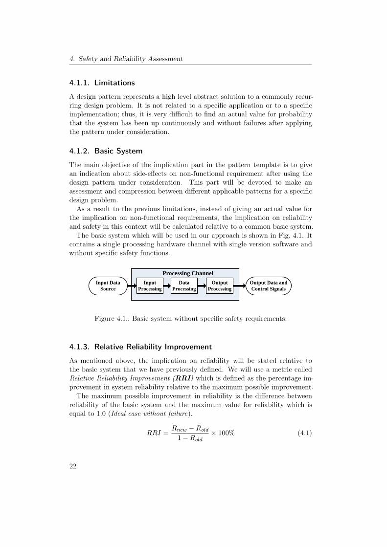
the implication on non-functional requirements, the implication on reliabilityand safety in this context will be calculated relative to a common basic system.The basic system which will be used in our approach is shown in Fig. 4.1. It
contains a single processing hardware channel with single version software andwithout specific safety functions.
Input Processing
Data Processing
Output Processing
Input Data Source
Processing Channel
Output Data and Control Signals
Figure 4.1.: Basic system without specific safety requirements.
4.1.3. Relative Reliability Improvement
As mentioned above, the implication on reliability will be stated relative tothe basic system that we have previously defined. We will use a metric calledRelative Reliability Improvement (RRI) which is defined as the percentage im-provement in system reliability relative to the maximum possible improvement.The maximum possible improvement in reliability is the difference between
reliability of the basic system and the maximum value for reliability which isequal to 1.0 (Ideal case without failure).
RRI =Rnew −Rold
1−Rold× 100% (4.1)
22
4.2. Safety Standards
− RRI: Relative reliability improvement.− Rold: Reliability of the basic system.− Rnew: Reliability after using the design pattern.
This metric can be easily applied in the assessment process of design patterns:either through employment of a mathematical modeling or by using simulationtechniques similar to the method used in our case study (see Chapter 5).
4.2. Safety Standards
In safety-critical embedded systems, ensuring adequate safety level representsthe major factor in the success of these systems. Often, there is no singlesafety technique that can be applied at a specific point to reach the desiredsafety requirement. Conversely, special aspects, requirements, techniques, andsafety management procedures should be considered in all stages of systemdevelopment lifecycle.Consequently, many safety standards have appeared in various domains, such
as military, automation, avionic, healthcare and general industry. These stan-dards have played a major role in the development of safety-critical systems byproviding a consistent safety management throughout their life-cycle.Four important safety standards from different fields are discussed briefly in
the following sections.
4.2.1. IEC 61508
IEC 61508 [46] is titled “Functional safety of electrical/electronic/programmableelectronic safety-related systems”. It is a generic industrial safety standard thatwas approved by the International Electrotechnical Commission (IEC) to coverfunctional safety in all safety-related systems that are electrotechnical in natureirrespective of their application. Therefore, it is intended to be applicable toany industrial safety-related system.The standard consists of seven parts that cover the complete safety life cycle.
The main three parts 1-3 present general functional safety management, hard-ware aspects and requirements, and requirements for software design of thesafety-related systems. Parts 4-7 provide supplementary material that includesdefinitions, abbreviations, examples, guidelines on the application of softwareand hardware requirements, and an overview of safety measures and techniques.(see e.g. [96] which gives a guide to applying the IEC 61508 standard)
23
4. Safety and Reliability Assessment
4.2.2. MIL-STD-882D
MIL-STD-882D [35], which is titled “Standard Practice for System Safety”, wasapproved for use as a military standard by the US Department of Defense(DoD) in 2000. It addresses the management of environmental, safety, andhealth mishap2 risks encountered in the development, test, production, use,and disposal of DoD systems, subsystems, equipment, and facilities. Moreover,it provides the basic safety requirements to perform throughout the life-cyclefor any safety-related system as well as guidelines to help user in applying thestandard.
4.2.3. ISO 26262
ISO/WD 26262 [48] is titled “Road vehicles - Functional safety”. It is the adap-tation of IEC 61508 to meet needs specific for automotive sector. The standardincludes ten parts to cover all activities during the safety life-cycle of safety-related systems consists of electrical, electronic, and software elements thatprovide safety-related functions.This standard uses automotive specific safety integrity levels instead of the
safety integrity levels 3 provided in IEC 61508. Similar to the other standards,it provides requirements for confirmation measures to ensure a sufficient andacceptable level of safety is achieved.
4.2.4. DO-178B and DO-254
DO-178B [91] and DO-254 [92] are two correlated standards issued by RTCA,Inc. and accepted by the Federal Aviation Administration to give guidanceon the development of safety-related systems in airborne environments. Theformer presents guidance that covers the development of software for airbornesystems, while the later covers the design of safety-related hardware in thesesystems.
4.2.5. Choice of standard for our work
Clearly, IEC 61508 is the most general standard that can be applied to anysafety-related system; thus, it has been used in our research to derive a safetyassessment method for design patterns that present abstract solutions.
2Mishap is defined in (MIL-STD-882D) as an unplanned event or series of events resultingin death, injury, occupational illness, damage to or loss of equipment or property, ordamage to the environment [35].
3See Section 4.4 for the concept of safety integrity levels
24
4.3. Safety and Risk Metrics
4.3. Safety and Risk Metrics
As shown in Section 2.3, system safety is related to the risk of failure in a systemand the analysis, techniques and procedures that should be conducted to reducethe risk to an acceptable level. In this context, there is a major concern aboutthe safety and risk assessment of these systems.In order to provide suitable safety assessment methods for the assessment
of safety-critical systems, there is a need for suitable safety and risk metrics.Therefore, many metrics, such as Steady-State Safety (SSS)4 and Mean Time toUnsafe Failure (MTTUF )5, have been proposed to be used in the assessmentof safety-critical systems (see e.g. [34]). Most of these metrics evaluate systemsafety as a function of time and do not concentrate on the consequences ofunsafe failures.Meanwhile, risk, which is defined in the standard IEC 61508 as a combination
of the probability of occurrence of harm6 and the severity of that harm, is con-sidered as the most generic metric that deals with a wide range of applications.The risk metric is based on the following equation:
R = C × f (4.2)
− R: the risk in the system.− C: the consequence of the hazardous event.− f : the frequency of the hazardous event.
The aim of the following sections is to construct an abstract safety metric,similar to the above generic risk metric, to be used in the assessment process ofdesign patterns.
4.4. Safety Integrity Levels
The first part of our safety metric is derived from the safety integrity levelspresented in IEC61508 standard; thus, this section gives a brief overview of theconcept of safety integrity levels.The term Safety Integrity as defined by IEC 61508 is “the likelihood of a safety-
related system satisfactorily performing the required safety function under allstated conditions within a stated period of time”. Unfortunately, the implications
4Steady-State Safety: a probability representing the evaluation of safety as a function oftime, in the limiting case as time approaches infinity [104].
5Mean Time to Unsafe Failure: the expected time that a system will operate before thefirst unsafe failure occurs [104].
6Harm: physical injury or damage to the health of people either directly or indirectly as aresult of damage to property or to the environment [46].
25
4. Safety and Reliability Assessment
of failure vary largely between different applications, which arises the need fora method to express the importance of correct and safe operation in a safety-related system.The idea is to divide the spectrum of integrity into discrete levels, which are
called Safety Integrity levels (SIL). A safety integrity level specifies the safetyintegrity requirements of the safety function to be allocated to the safety-relatedsystem.The concept of safety integrity levels have been adopted by many safety stan-
dards. IEC 61508 standard defines discrete levels for specifying the safety in-tegrity requirements of safety functions to be allocated to the system. Theselevels range from level 1 (SIL1 ) to level 4 (SIL4 ), where safety integrity level 4denotes the highest level of safety integrity. Like IEC 61508, ISO 2626 definesautomotive safety integrity levels (ASIL) which include four levels (A-D). Also,MISRA7 guidelines [73] include five levels that are defined qualitatively ratherthan mapping integrity to numerical range [96].Despite the different notations and classifications used for safety integrity
levels in safety standards, this concept represents a useful approach to show theimportance and implication of correct operation in a safety-related system.
4.5. Safety Assessment
While several assessment methods have been used to evaluate safety-criticalsystems, most of these methods can not be used to assess safety-critical designpatterns due to the abstract nature of these patterns.The objective of this part is to provide a safety and risk metric that can be
used to show the implication of design patterns on safety and also to facilitatethe assessment process of design patterns for safety-critical embedded systems.This metric is derived from the general risk metric shown in Equation (4.2).
Unlike real safety-critical systems, design patterns are abstract solutions thatare not related to specific applications or implementations. Consequently, it isvery difficult to find actual values for both the frequency of hazardous event(f) and the consequences of the hazardous event (C). This limitation revealsthe need for new parameters that can be used to reflect the idea of the origi-nal parameters, the frequency of hazardous event and the consequences of thehazardous event, in the context of design patterns.
7MISRA: Motor Industry Software Reliability Association (see http://www.misra.org.uk/)
26
4.5. Safety Assessment
4.5.1. Applicability to Safety Integrity Levels
The first part of our risk metric is based on the safety integrity levels presentedby the IEC61508 standard. While a safety integrity level is derived from anassessment of risk, it is not a measure of risk [86]. The safety integrity levelswill be used in the first component of the risk metric as an indication of severityof failures in the considered application after applying a specific design pattern.The IEC 61508 standard provides a method to show the importance of design
methods, techniques, and measures that are applied in order to avoid safety-critical failures caused by hardware and software. This method includes rec-ommendations for these techniques and measures. These recommendations aredependent on safety integrity levels and classified according to their importanceinto four types [46]:
• HR: the technique is highly recommended for this safety integrity level.
• R : the technique is recommended for this safety integrity level
• – : the technique has no recommendation for or against used.
• NR: the technique is positively not recommended for this safety integritylevel.
It is important to note that the use of these recommendations does not guaranteethe satisfaction of the required safety integrity in the final design. Instead, thestandard should be followed throughout the entire life-cycle in order to get acertificate for a specific safety integrity level.While the safety recommendations are given in IEC 61508 for different soft-
ware and hardware techniques, these recommendations can not be directly de-rived for general design patterns or architectures. Usually, a design patternpresents a combination of different techniques and design methods that coop-erate to improve more system properties. Hence, it is necessary to provide amethod that can be applied to derive general safety recommendations for safetyintegrity levels at the abstract level of design patterns.
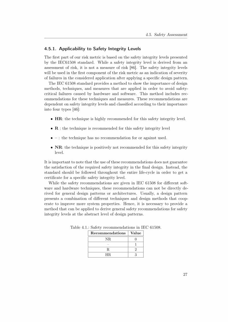
Table 4.1.: Safety recommendations in IEC 61508.Recommendations Value
NR 0– 1R 2HR 3
27
4. Safety and Reliability Assessment
The first step in our approach is to assign equivalent integer values for thedifferent recommendations as shown in Tab. 4.1 The second step is to computean equivalent integer number for the design pattern under consideration. Sinceit is difficult to estimate the different effects of the different techniques that con-structs a design pattern, it is not possible to use heuristic or different weights forthese techniques. Consequently, equivalent weights are assigned to the existingtechniques and the average value is calculated for each safety integrity level tofind the safety recommendations for design patterns.
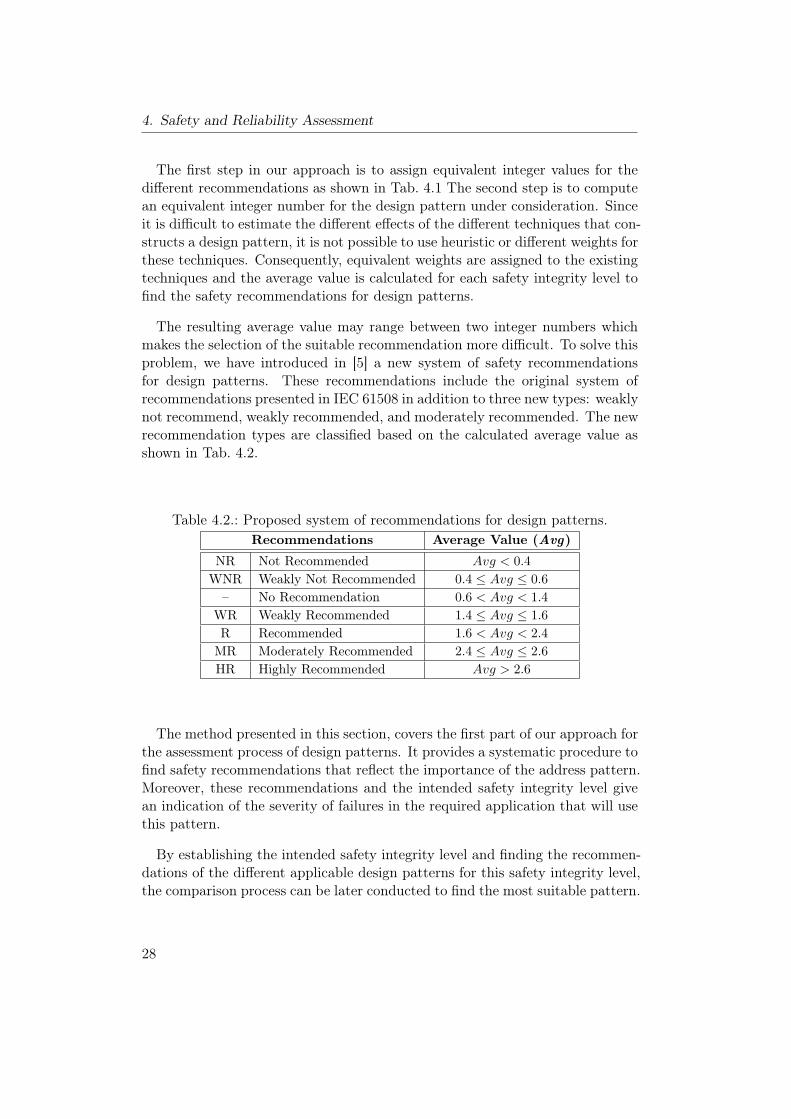
The resulting average value may range between two integer numbers whichmakes the selection of the suitable recommendation more difficult. To solve thisproblem, we have introduced in [5] a new system of safety recommendationsfor design patterns. These recommendations include the original system ofrecommendations presented in IEC 61508 in addition to three new types: weaklynot recommend, weakly recommended, and moderately recommended. The newrecommendation types are classified based on the calculated average value asshown in Tab. 4.2.
Table 4.2.: Proposed system of recommendations for design patterns.Recommendations Average Value (Avg)
NR Not Recommended Avg < 0.4WNR Weakly Not Recommended 0.4 ≤ Avg ≤ 0.6
– No Recommendation 0.6 < Avg < 1.4WR Weakly Recommended 1.4 ≤ Avg ≤ 1.6R Recommended 1.6 < Avg < 2.4MR Moderately Recommended 2.4 ≤ Avg ≤ 2.6HR Highly Recommended Avg > 2.6
The method presented in this section, covers the first part of our approach forthe assessment process of design patterns. It provides a systematic procedure tofind safety recommendations that reflect the importance of the address pattern.Moreover, these recommendations and the intended safety integrity level givean indication of the severity of failures in the required application that will usethis pattern.
By establishing the intended safety integrity level and finding the recommen-dations of the different applicable design patterns for this safety integrity level,the comparison process can be later conducted to find the most suitable pattern.
28
4.5. Safety Assessment
4.5.2. Relative Safety Improvement
Although safety and reliability of a safety-critical system are both highly relatedto the probability of failures, they differ on the type of failure, whether it is safeor unsafe. While reliability refers to the continuity of correct service, safetyrequirement addresses the severity of failures. Therefore, most of the safetydesign methods usually concentrate on dealing with unsafe failures8.Since the aim of this section is to provide a parameter that can be used in our
approach to cover the second part, frequency of hazardous event, of the generalrisk metric shown in Equation (4.2), we will consider the probability of unsafefailure (PUF ) in our metric for risk assessment.As shown in the reliability assessment, it is difficult to find actual values for
this probability due to the abstract nature of design patterns. Hence, this proba-bility will be calculated, like in reliability assessment, relative to the probabilityof unsafe failure in the basic system. If the basic system has a given reliability(R), then we will consider the probability of failure to be (PF = 1−R). Thesefailures can be divided into two groups: safe and unsafe failures. For any system,the worst case occurs when all failures are unsafe; thus we assume all failuresin the basic system to be unsafe to indicate the worst case.To cover the second factor of the risk metric, we have proposed in [4] a new
metric called Relative Safety Improvement (RSI). This metric is defined as “thepercentage improvement in safety (reduction in probability of unsafe failure)relative to the maximum possible improvement which can be achieved whenthe probability of unsafe failure is reduced to the minimum possible value (0)”.Based on this definition, the relative safety improvement for a design pattern
can be expressed as shown in Equation (4.3).
RSI =PUF (new) − PUF (old)
0− PUF (old)× 100%
RSI = (1−PUF (new)
PUF (old))× 100%
(4.3)
− RSI: Relative Safety Improvement.− PUF (old): Probability of unsafe failure in the basic system.− PUF (new): Probability of unsafe failure in the design pattern.
In general, the combination of this metric and the previous system of safetyrecommendations provides a systematic method to assess design patterns forsafety-critical systems. This method can be summarized as follows:
8Unsafe (dangerous) failure: a failure which has the potential to put the system in ahazardous state [46].
29
4. Safety and Reliability Assessment
• The first step is to find the intended safety integrity level for the requiredapplication, or to conduct the next two steps for all safety integrity levelsto provide a general assessment.
• The next step is to determine the safety recommendations which showthe applicability of the design pattern under consideration to the safetyintegrity level(s).
• The final step is to compute the relative safety improvement which givesan indication about the safety improvement that can be achieved by thispattern. Furthermore, the safety metric can be used to investigate theeffects of the individual parameters that affect the success of design pat-terns.
Finally, the relative safety improvement metric and the relative reliabilityimprovement can be used in an analogous way. They can be computed using asimulation method (see Chapter 5) or through the employment of a mathemat-ical model for design patterns as being done in our catalog of design patterns(see Chapter 7, 8, and 9).
30

5. A Case Study: Software Diversity
This chapter describes a case study conducted to illustrate safety and reliabil-ity assessment methods for design patterns. A Monte Carlo based simulationmethod has been used in this case study to demonstrate the use of the safety andreliability metrics by making an assessment for four software design patternsthat share the concept of diversity programming.This chapter includes two parts: the first part presents the basic concept of
diversity programming, effects of a good acceptance test, and the basic ideaof the recovery block with backup voting pattern (Section 5.1-5.4), while thesecond part includes the simulation procedure, reliability and safety assessmentof software patterns (Section 5.5-5.7).The basic idea of the recovery block with backup voting method was published
in [7, 8], and part of the simulation results of reliability and safety assessmentwere published in [4, 7].
5.1. Concept of Diversity Programming
Software faults that may remain after software development process representone of the critical reasons for unsafe failures in safety-critical system. Therefore,Diversity Programming or Software Design Diversity has been used for a longtime as a major fault tolerance method in the design of software for safety-critical systems. It involves the independent generation of N ≥ 2 functionallyequivalent software modules called versions from the same initial specificationby N independent teams of programmers. These versions can be executedin different ways depending on the used architecture. Moreover, the conceptof diversity programming can be integrated with other techniques, like faultmasking and fault detection, to construct different design methods.Consequently, many design methods, that use the principle of software design
diversity, have been proposed to be used as fault tolerance methods in the designof safety-critical systems. In our catalog of design patterns, we have includedfive design methods, which share the concept of software diversity, as designpatterns (see Chapter 8).In this case study, the following design methods were simulated and assessed
to illustrate the basic idea of the proposed safety and reliability assessmentmetrics:
31
5. A Case Study: Software Diversity
• N-Version Programming (NVP) [13]: NVP is the most well knownfault-tolerant software method based on software diversity and fault mask-ing. It runs the diverse versions in parallel on N hardware modules anduses a voting technique to perform a fault masking.
• Recovery Block (RB) [84]: in RB, which is based on fault detection,the independent software versions are executed sequentially followed byan acceptance test (AT ) on a single hardware component. After theexecution of the first version, the acceptance test is executed to checkif the outcome is reasonable and to detect any possible erroneous result.If the acceptance test is passed, then the outcome is considered as true.Otherwise, if a fault is detected, the system state should be restored to itsoriginal state and an alternate version will be invoked to repeat the samecomputations. This process is repeated until either one of the alternateversions passes the test and gives the result, or no more versions areavailable. In the last case, an overall system failure is reported to executethe available safety function.
• Acceptance Voting (AV) [10]: the AV pattern integrates the concept ofvoting from NVP with the acceptance test used in the RB. This patternexecutes the diverse versions in parallel on N hardware modules. Theoutput of each version is evaluated for correctness using an acceptancetest, and only those results, that pass the acceptance test, are used bythe voting algorithm to generate the final result. The goal of the AV isto mask the faulty outputs from participating in the voting process.
• Recovery Block with Backup Voting (RBBV) [7, 8]: RBBV is anextension to the classical RB pattern. It improves the reliability of theclassical RB in those situations where it is difficult to construct an effectiveacceptance test. (see Section 5.2 and 5.4)
5.2. Acceptance Test
The acceptance test is a fault detection mechanism that can be used in faulttolerance design. In this fault detection method, the program is executed andthe result is subjected to a test to confirm that the result is reasonable and toverify the correctness of calculations based on the software specifications. If theresult passes the test, it is considered to be true. Otherwise, it is an indicationof a fault.The acceptance test method can be applied to a single module or to the
complete software. It may have several components and may include checks forruntime errors [97] and mechanisms for implicit error detection.
32
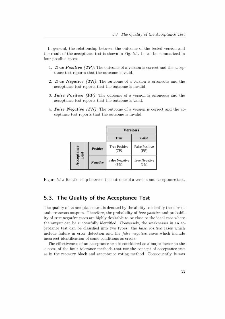
5.3. The Quality of the Acceptance Test
In general, the relationship between the outcome of the tested version andthe result of the acceptance test is shown in Fig. 5.1. It can be summarized infour possible cases:
1. True Positive (TP): The outcome of a version is correct and the accep-tance test reports that the outcome is valid.
2. True Negative (TN): The outcome of a version is erroneous and theacceptance test reports that the outcome is invalid.
3. False Positive (FP): The outcome of a version is erroneous and theacceptance test reports that the outcome is valid.
4. False Negative (FN): The outcome of a version is correct and the ac-ceptance test reports that the outcome is invalid.
Version i
True False
Positive True Positive
(TP) False Positive
(FP)
Acc
epta
nce
T
est
Negative False Negative
(FN) True Negative
(TN)
Figure 5.1.: Relationship between the outcome of a version and acceptance test.
5.3. The Quality of the Acceptance Test
The quality of an acceptance test is denoted by the ability to identify the correctand erroneous outputs. Therefore, the probability of true positive and probabil-ity of true negative cases are highly desirable to be close to the ideal case wherethe output can be successfully identified. Conversely, the weaknesses in an ac-ceptance test can be classified into two types: the false positive cases whichinclude failure in error detection and the false negative cases which includeincorrect identification of some conditions as errors.The effectiveness of an acceptance test is considered as a major factor to the
success of the fault tolerance methods that use the concept of acceptance testas in the recovery block and acceptance voting method. Consequently, it was
33
5. A Case Study: Software Diversity
shown in many studies [50, 85, 95] that the acceptance test should be carefullydesigned, reasonably simple, highly reliable, and with a high error detectioncoverage.The competing goals of the desired acceptance test make the construction
of an effective acceptance for some safety-critical systems very difficult. Thisdifficulty will be reflected in a weakness in the acceptance test, which may thenbecome a source of failure and may affect negatively the system safety andreliability. The effects of the two types of weakness in an acceptance test varybetween safety and reliability. While false negative cases only affect reliability,the false positive cases affect both safety and reliability.In order to alleviate the effect of a weak acceptance test, the concept of
diversity can be applied to the acceptance test. In this case, multiple acceptancetests are independently developed by different teems to be used in conjunctionwith diverse software versions. This approach was applied in N-self checkingprogramming using acceptance test [61, 59, 60], where the main difference ofthis method from the classical recovery block is the use of a separate acceptancetest for each version (block).In multiple acceptance test approach, the probability of concurrent failures
in the acceptance test will be less than in the case of a single acceptance test,which will improve safety and reliability. On the other hand, constructing Ndiverse effective acceptance tests will be more difficult and costly than in thecase of a single acceptance test.
5.4. Recovery Block with Backup Voting
The effect of false negative cases can be shown clearly in the classical recoveryblock method with a single acceptance test. In the recovery block method, ifall the versions fail to pass the acceptance test, an overall system failure will bereported. The reason for this failure can be one of the following two cases:
1. All the versions fail concurrently to produce a correct result (correlatedfailures) and the acceptance test detects these failures.
2. There are some correct outcomes from some versions, but there is a fail-ure in the acceptance test, which represents a false negative case in theacceptance test.
In the first case, the correlated failures are not related to the used acceptancetest. It can be only improved by employing more techniques to increase the leveldiversity in software versions. To solve the second problem, we have proposedin [7] a new hybrid method called Recovery Block with Backup Voting (RBBV).
34
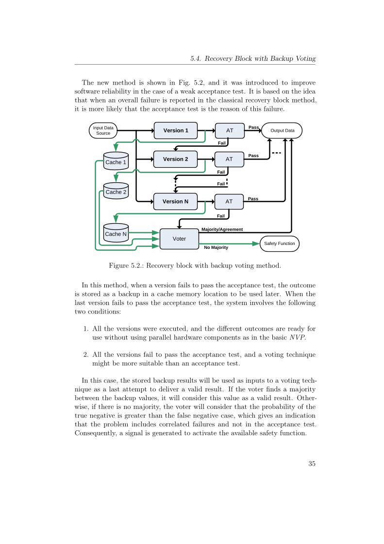
5.4. Recovery Block with Backup Voting
The new method is shown in Fig. 5.2, and it was introduced to improvesoftware reliability in the case of a weak acceptance test. It is based on the ideathat when an overall failure is reported in the classical recovery block method,it is more likely that the acceptance test is the reason of this failure.
Input Data Source AT Output Data Version 1
ATVersion 2
ATVersion N
Safety Function Voter
Cache 1
Cache 2
Cache N
Pass
Pass
Fail
Fail
Pass
Fail
Fail
No Majority
Majority/Agreement
Figure 5.2.: Recovery block with backup voting method.
In this method, when a version fails to pass the acceptance test, the outcomeis stored as a backup in a cache memory location to be used later. When thelast version fails to pass the acceptance test, the system involves the followingtwo conditions:
1. All the versions were executed, and the different outcomes are ready foruse without using parallel hardware components as in the basic NVP.
2. All the versions fail to pass the acceptance test, and a voting techniquemight be more suitable than an acceptance test.
In this case, the stored backup results will be used as inputs to a voting tech-nique as a last attempt to deliver a valid result. If the voter finds a majoritybetween the backup values, it will consider this value as a valid result. Other-wise, if there is no majority, the voter will consider that the probability of thetrue negative is greater than the false negative case, which gives an indicationthat the problem includes correlated failures and not in the acceptance test.Consequently, a signal is generated to activate the available safety function.
35
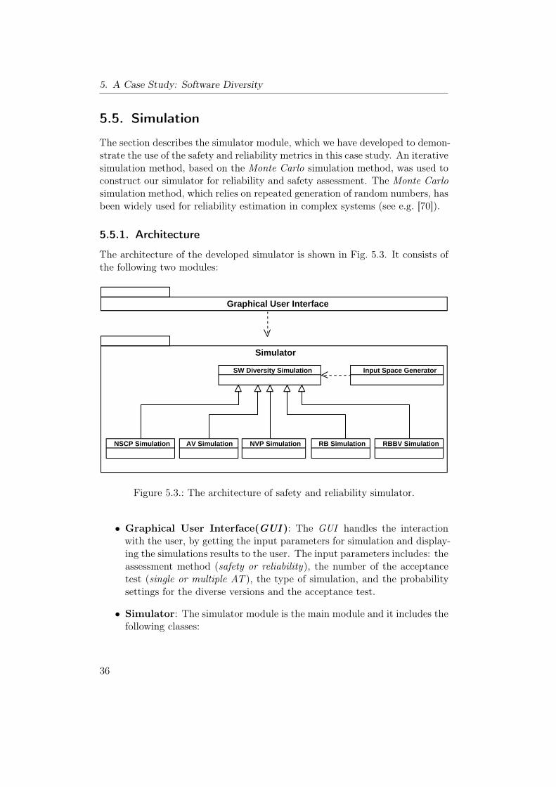
5. A Case Study: Software Diversity
5.5. Simulation
The section describes the simulator module, which we have developed to demon-strate the use of the safety and reliability metrics in this case study. An iterativesimulation method, based on the Monte Carlo simulation method, was used toconstruct our simulator for reliability and safety assessment. The Monte Carlosimulation method, which relies on repeated generation of random numbers, hasbeen widely used for reliability estimation in complex systems (see e.g. [70]).
5.5.1. Architecture
The architecture of the developed simulator is shown in Fig. 5.3. It consists ofthe following two modules:
Class Diagram1
Graphical User Interface
Simulator
SW Diversity Simulation
NVP SimulationAV Simulation RB Simulation RBBV SimulationNSCP Simulation
Input Space Generator
Visual Paradigm for UML Standard Edition(RWTH Aachen)
Figure 5.3.: The architecture of safety and reliability simulator.
• Graphical User Interface(GUI ): The GUI handles the interactionwith the user, by getting the input parameters for simulation and display-ing the simulations results to the user. The input parameters includes: theassessment method (safety or reliability), the number of the acceptancetest (single or multiple AT ), the type of simulation, and the probabilitysettings for the diverse versions and the acceptance test.
• Simulator: The simulator module is the main module and it includes thefollowing classes:
36
5.5. Simulation
– A general base class that provides the basic variables and simulationmethods for any design method that uses the concept of SW diversity.
– Five derived classes that inherit the base class and provide instant im-plementations for five different fault tolerance design methods. Theseclasses cover N-version programming, acceptance voting, N-self check-ing programming , recovery block, and recovery block with backup vot-ing method.
– A class that serves to randomly generate the input spaces for thedifferent versions. The generated input spaces depend on the numberof versions and the input parameters collected from the GUI.
5.5.2. Simulation Procedure
The procedure for safety and reliability simulation includes input data collec-tion, construction of input spaces, execution of the selected methods, and thedisplaying of the simulation result.The first step in our simulation is to collect the input parameters from theGUI
to determine the simulation methods to be used, the parameters to construct theinput spaces, and the acceptance test setting. In the second step, an input spaceof size 106 is constructed by the input space generator for each version. Eachelement in an input space contains a Boolean variable to indicate if this versionproduces a correct or faulty result for this element. The fault-causing inputsare scattered randomly in an input space according to the given probability offailure. In order to provide independent executions, the last step is repeated ineach iteration of simulation.In the first part of this simulation, we assume that the alternate versions
fail independently which is reflected by the independent generation of the fault-causing inputs for the alternate versions. Nevertheless, dependent (or corre-lated) faults can be modeled in our simulator by adding fault-causing inputs atidentical positions in the input spaces of the alternate versions based on a givencriteria. This criteria depends entirely on the number of correlated versions andthe relative ratio of the correlated failures to the total number of failures.The next step involves the execution of the selected simulation of the used
design methods on the generated input spaces. The execution is repeated forthe given number of iterations, where fresh input spaces are generated in eachiteration. The average value for the results of these iterations is calculated togive the final simulation result.The final step involves the display of the final result using the GUI module.
It provides two display methods: a graph display for scanning simulation anda text display for single-value simulation.
37
5. A Case Study: Software Diversity
5.5.3. Notations and Assumptions
In the next two sections, we will use the following notations and assumption:
Notations
f probability of failure in a version.
N number of alternate versions.
PTP probability of true positive cases in the acceptance test.
PTN probability of true negative cases in the acceptance test.
PFP probability of true positive cases in the acceptance test.
PFN probability of false negative cases in the acceptance test.
RRI relative reliability improvement.
RSI relative safety improvement.
Assumptions
1. All software versions are functionally equivalent.
2. All software versions have equal probability of failure.
3. A simple majority voting technique is used in the voter.
4. Multiple acceptance tests are considered to be independent. Nevertheless,the dependency between multiple acceptance tests could be modeled inour simulator in the same way as in the correlated alternate versions.
5.6. Reliability Assessment
This section illustrates how the proposed reliability metric can be used in thereliability assessment of design patterns. It covers the reliability assessment ofthe software design patterns under consideration and the effects of the mainfactors that influence the reliability of these patterns.
38
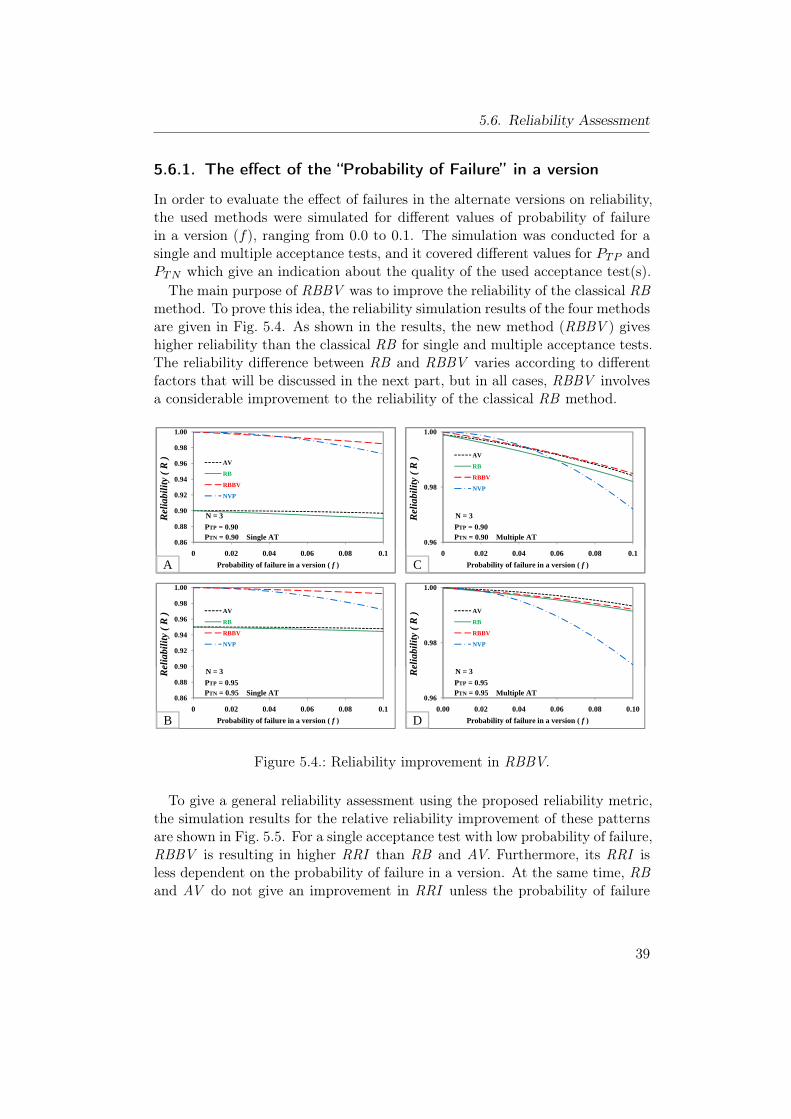
5.6. Reliability Assessment
5.6.1. The effect of the “Probability of Failure” in a version
In order to evaluate the effect of failures in the alternate versions on reliability,the used methods were simulated for different values of probability of failurein a version (f), ranging from 0.0 to 0.1. The simulation was conducted for asingle and multiple acceptance tests, and it covered different values for PTP andPTN which give an indication about the quality of the used acceptance test(s).The main purpose of RBBV was to improve the reliability of the classical RB
method. To prove this idea, the reliability simulation results of the four methodsare given in Fig. 5.4. As shown in the results, the new method (RBBV ) giveshigher reliability than the classical RB for single and multiple acceptance tests.The reliability difference between RB and RBBV varies according to differentfactors that will be discussed in the next part, but in all cases, RBBV involvesa considerable improvement to the reliability of the classical RB method.
0.86
0.88
0.90
0.92
0.94
0.96
0.98
1.00
AV
RB
RBBV
NVP
PTP = 0.90PTN = 0.90 Single AT
N = 3Rel
iabi
lity
( R
)
0.96
0.98
1.00
AV
RB
RBBV
NVP
PTP = 0.90PTN = 0.90 Multiple AT
N = 3Rel
iabi
lity
( R
)
0.86
0.88
0.90
0.92
0.94
0.96
0.98
1.00
0 0.02 0.04 0.06 0.08 0.1
AV
RB
RBBV
NVP
PTP = 0.90PTN = 0.90 Single AT
N = 3
Probability of failure in a version ( f )
Rel
iabi
lity
( R
)
A
0 90
0.92
0.94
0.96
0.98
1.00
AV
RB
RBBV
NVP
elia
bili
ty (
R )
0.96
0.98
1.00
0 0.02 0.04 0.06 0.08 0.1
AV
RB
RBBV
NVP
PTP = 0.90PTN = 0.90 Multiple AT
N = 3
Probability of failure in a version ( f )
Rel
iabi
lity
( R
)
C
0.98
1.00
AV
RB
RBBV
NVP
elia
bili
ty (
R )
0.86
0.88
0.90
0.92
0.94
0.96
0.98
1.00
0 0.02 0.04 0.06 0.08 0.1
AV
RB
RBBV
NVP
PTP = 0.90PTN = 0.90 Single AT
N = 3
Probability of failure in a version ( f )
Rel
iabi
lity
( R
)
A
0.86
0.88
0.90
0.92
0.94
0.96
0.98
1.00
0 0.02 0.04 0.06 0.08 0.1
AV
RB
RBBV
NVP
PTP = 0.95PTN = 0.95 Single AT
N = 3
Probability of failure in a version ( f )
Rel
iabi
lity
( R
)
B
0.96
0.98
1.00
0 0.02 0.04 0.06 0.08 0.1
AV
RB
RBBV
NVP
PTP = 0.90PTN = 0.90 Multiple AT
N = 3
Probability of failure in a version ( f )
Rel
iabi
lity
( R
)
C
0.96
0.98
1.00
0.00 0.02 0.04 0.06 0.08 0.10
AV
RB
RBBV
NVP
PTP = 0.95PTN = 0.95 Multiple AT
N = 3
Probability of failure in a version ( f )
Rel
iabi
lity
( R
)
D
Figure 5.4.: Reliability improvement in RBBV.
To give a general reliability assessment using the proposed reliability metric,the simulation results for the relative reliability improvement of these patternsare shown in Fig. 5.5. For a single acceptance test with low probability of failure,RBBV is resulting in higher RRI than RB and AV. Furthermore, its RRI isless dependent on the probability of failure in a version. At the same time, RBand AV do not give an improvement in RRI unless the probability of failure
39
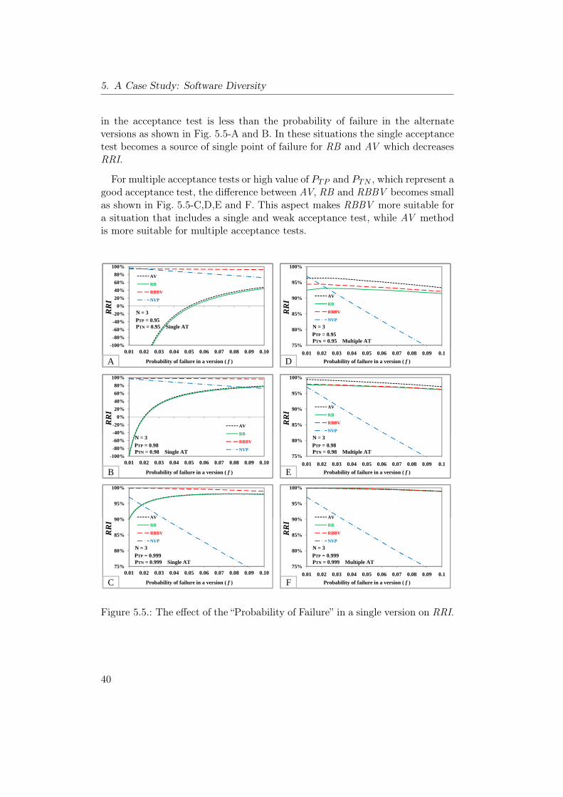
5. A Case Study: Software Diversity
in the acceptance test is less than the probability of failure in the alternateversions as shown in Fig. 5.5-A and B. In these situations the single acceptancetest becomes a source of single point of failure for RB and AV which decreasesRRI.
For multiple acceptance tests or high value of PTP and PTN , which represent agood acceptance test, the difference between AV, RB and RBBV becomes smallas shown in Fig. 5.5-C,D,E and F. This aspect makes RBBV more suitable fora situation that includes a single and weak acceptance test, while AV methodis more suitable for multiple acceptance tests.
-100%
-80%
-60%
-40%
-20%
0%
20%
40%
60%
80%
100%
AV
RB
RBBV
NVP
PTP = 0.95PTN = 0.95 Single AT
N = 3RR
I
75%
80%
85%
90%
95%
100%
AV
RB
RBBV
NVP
PTP = 0.95PTN = 0.95 Multiple AT
N = 3
RR
I
-100%
-80%
-60%
-40%
-20%
0%
20%
40%
60%
80%
100%
0.01 0.02 0.03 0.04 0.05 0.06 0.07 0.08 0.09 0.10
AV
RB
RBBV
NVP
PTP = 0.95PTN = 0.95 Single AT
N = 3
Probability of failure in a version ( f )
RR
I
A
-40%
-20%
0%
20%
40%
60%
80%
100%
AV
RB
RR
I
75%
80%
85%
90%
95%
100%
0.01 0.02 0.03 0.04 0.05 0.06 0.07 0.08 0.09 0.1
AV
RB
RBBV
NVP
PTP = 0.95PTN = 0.95 Multiple AT
N = 3
Probability of failure in a version ( f )
RR
I
D
85%
90%
95%
100%
AV
RB
RBBV
NVP
RR
I
-100%
-80%
-60%
-40%
-20%
0%
20%
40%
60%
80%
100%
0.01 0.02 0.03 0.04 0.05 0.06 0.07 0.08 0.09 0.10
AV
RB
RBBV
NVP
PTP = 0.95PTN = 0.95 Single AT
N = 3
Probability of failure in a version ( f )
RR
I
A
-100%
-80%
-60%
-40%
-20%
0%
20%
40%
60%
80%
100%
0.01 0.02 0.03 0.04 0.05 0.06 0.07 0.08 0.09 0.10
AV
RB
RBBV
NVPPTP = 0.98PTN = 0.98 Single AT
N = 3
Probability of failure in a version ( f )
RR
I
B
90%
95%
100%
AV
75%
80%
85%
90%
95%
100%
0.01 0.02 0.03 0.04 0.05 0.06 0.07 0.08 0.09 0.1
AV
RB
RBBV
NVP
PTP = 0.95PTN = 0.95 Multiple AT
N = 3
Probability of failure in a version ( f )
RR
I
D
75%
80%
85%
90%
95%
100%
0.01 0.02 0.03 0.04 0.05 0.06 0.07 0.08 0.09 0.1
AV
RB
RBBV
NVP
PTP = 0.98PTN = 0.98 Multiple AT
N = 3
Probability of failure in a version ( f )
RR
I
E
90%
95%
100%
AV
-100%
-80%
-60%
-40%
-20%
0%
20%
40%
60%
80%
100%
0.01 0.02 0.03 0.04 0.05 0.06 0.07 0.08 0.09 0.10
AV
RB
RBBV
NVP
PTP = 0.95PTN = 0.95 Single AT
N = 3
Probability of failure in a version ( f )
RR
I
A
-100%
-80%
-60%
-40%
-20%
0%
20%
40%
60%
80%
100%
0.01 0.02 0.03 0.04 0.05 0.06 0.07 0.08 0.09 0.10
AV
RB
RBBV
NVPPTP = 0.98PTN = 0.98 Single AT
N = 3
Probability of failure in a version ( f )
RR
I
B
75%
80%
85%
90%
95%
100%
0.01 0.02 0.03 0.04 0.05 0.06 0.07 0.08 0.09 0.10
AV
RB
RBBV
NVP
PTP = 0.999PTN = 0.999 Single AT
N = 3
Probability of failure in a version ( f )
RR
I
C
75%
80%
85%
90%
95%
100%
0.01 0.02 0.03 0.04 0.05 0.06 0.07 0.08 0.09 0.1
AV
RB
RBBV
NVP
PTP = 0.95PTN = 0.95 Multiple AT
N = 3
Probability of failure in a version ( f )
RR
I
D
75%
80%
85%
90%
95%
100%
0.01 0.02 0.03 0.04 0.05 0.06 0.07 0.08 0.09 0.1
AV
RB
RBBV
NVP
PTP = 0.98PTN = 0.98 Multiple AT
N = 3
Probability of failure in a version ( f )
RR
I
E
75%
80%
85%
90%
95%
100%
0.01 0.02 0.03 0.04 0.05 0.06 0.07 0.08 0.09 0.1
AV
RB
RBBV
NVP
PTP = 0.999PTN = 0.999 Multiple AT
N = 3
Probability of failure in a version ( f )
RR
I
F
Figure 5.5.: The effect of the “Probability of Failure” in a single version on RRI.
40

5.6. Reliability Assessment
5.6.2. The effect of the false negative cases in the acceptance test
As described above, the weakness in an acceptance test can be described bythe failure to identify correct and erroneous results. In this part of simulation,the effect of false negative cases in the acceptance test is investigated in themethods that use acceptance tests, by varying the probability of false negativecases (PFN = 1−PTP ) from 0.0 to 0.1 for single and multiple acceptance tests.
0%
20%
40%
60%
80%
100%
AV
RB
RBBV
f = 0.1PTN = 0.95 Single AT
N = 3
RR
I
60%
70%
80%
90%
100%
AV
RB
RBBV
f = 0.1PTN = 0.95 Multiple AT
N = 3R
RI
0%
20%
40%
60%
80%
100%
0.00 0.01 0.02 0.03 0.04 0.05 0.06 0.07 0.08 0.09 0.10
AV
RB
RBBV
f = 0.1PTN = 0.95 Single AT
N = 3
Probability of false negative (PFN=1-PTP)
RR
I
A
60%
70%
80%
90%
100%
0.00 0.01 0.02 0.03 0.04 0.05 0.06 0.07 0.08 0.09 0.10
AV
RB
RBBV
f = 0.1PTN = 0.95 Multiple AT
N = 3
Probability of false negative (PFN=1-PTP)
RR
I
B
Figure 5.6.: The effect of the probability of false negative cases in AT on RRI.
The simulation result in Fig. 5.6-A shows that AV and RB involve highreliability degradation as PFN increases, while the degradation in RBBV is lessdependent on PFN . Fig. 5.6-B shows that for the case of multiple acceptancetests and a low value of PFN , AV method gives higher RRI than RB and RBBV.Meanwhile, the high dependency of AV and RB on PFN proves that RBBV ismore suitable for the situation that includes accepatnce test with high value ofPFN .
0%
20%
40%
60%
80%
100%
AV
RB
RBBV
f = 0.1PTP = 0.95 Single AT
N = 3
RR
I
60%
70%
80%
90%
100%
AV
RB
RBBV
f = 0.1PTP = 0.95 Multiple AT
N = 3
RR
I
0%
20%
40%
60%
80%
100%
0.00 0.01 0.02 0.03 0.04 0.05 0.06 0.07 0.08 0.09 0.10
AV
RB
RBBV
f = 0.1PTP = 0.95 Single AT
N = 3
Probability of false positive (PFP=1-PTN)
RR
I
A
60%
70%
80%
90%
100%
0.00 0.01 0.02 0.03 0.04 0.05 0.06 0.07 0.08 0.09 0.10
AV
RB
RBBV
f = 0.1PTP = 0.95 Multiple AT
N = 3
Probability of false positive (PFP=1-PTN)
RR
I
B
Figure 5.7.: The effect of the probability of false postive cases in AT on RRI.
41
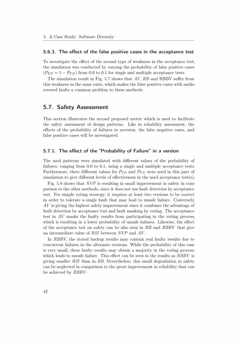
5. A Case Study: Software Diversity
5.6.3. The effect of the false positive cases in the acceptance test
To investigate the effect of the second type of weakness in the acceptance test,the simulation was conducted by varying the probability of false positive cases(PFP = 1− PTN ) from 0.0 to 0.1 for single and multiple acceptance tests.
The simulation result in Fig. 5.7 shows that AV, RB and RBBV suffer fromthis weakness in the same ratio, which makes the false positive cases with undis-covered faults a common problem to these methods.
5.7. Safety Assessment
This section illustrates the second proposed metric which is used to facilitatethe safety assessment of design patterns. Like in reliability assessment, theeffects of the probability of failures in aversion, the false negative cases, andfalse positive cases will be investigated.
5.7.1. The effect of the “Probability of Failure” in a version
The used patterns were simulated with different values of the probability offailures, ranging from 0.0 to 0.1, using a single and multiple acceptance tests.Furthermore, three different values for PTP and PTN were used in this part ofsimulation to give different levels of effectiveness in the used acceptance test(s).Fig. 5.8 shows that NVP is resulting in small improvement in safety in com-
parison to the other methods, since it does not use fault detection by acceptancetest. For simple voting strategy, it requires at least two versions to be correctin order to tolerate a single fault that may lead to unsafe failure. Conversely,AV is giving the highest safety improvement since it combines the advantage offault detection by acceptance test and fault masking by voting. The acceptancetest in AV masks the faulty results from participating in the voting process,which is resulting in a lower probability of unsafe failures. Likewise, the effectof the acceptance test on safety can be also seen in RB and RBBV that givean intermediate value of RSI between NVP and AV.In RBBV, the stored backup results may contain real faulty results due to
concurrent failures in the alternate versions. While the probability of this caseis very small, these faulty results may obtain a majority in the voting process,which leads to unsafe failure. This effect can be seen in the results as RBBV isgiving smaller RSI than in RB. Nevertheless, this small degradation in safetycan be neglected in comparison to the great improvement in reliability that canbe achieved by RBBV.
42
5.7. Safety Assessment
80%
85%
90%
95%
100%
AV
RB
RBBV
NVP
PTP = 0.95PTN = 0.95 Single AT
N = 3
RSI
80%
85%
90%
95%
100%
AV
RB
RBBV
NVP
PTP = 0.95PTN = 0.95 Multiple AT
N = 3
RSI
80%
85%
90%
95%
100%
0.00 0.01 0.02 0.03 0.04 0.05 0.06 0.07 0.08 0.09 0.10
AV
RB
RBBV
NVP
PTP = 0.95PTN = 0.95 Single AT
N = 3
Probability of failure in a version ( f )
RSI
A
90%
95%
100%
AV
RB
RBBV
NVP
RSI
80%
85%
90%
95%
100%
0.00 0.01 0.02 0.03 0.04 0.05 0.06 0.07 0.08 0.09 0.10
AV
RB
RBBV
NVP
PTP = 0.95PTN = 0.95 Multiple AT
N = 3
Probability of failure in a version ( f )
RSI
D
90%
95%
100%
AV
RB
RBBV
NVP
RSI
80%
85%
90%
95%
100%
0.00 0.01 0.02 0.03 0.04 0.05 0.06 0.07 0.08 0.09 0.10
AV
RB
RBBV
NVP
PTP = 0.95PTN = 0.95 Single AT
N = 3
Probability of failure in a version ( f )
RSI
A
80%
85%
90%
95%
100%
0.00 0.01 0.02 0.03 0.04 0.05 0.06 0.07 0.08 0.09 0.10
AV
RB
RBBV
NVP
PTP = 0.98PTN = 0.98 Single AT
N = 3
Probability of failure in a version ( f )
RSI
B
95%
100%
AV
80%
85%
90%
95%
100%
0.00 0.01 0.02 0.03 0.04 0.05 0.06 0.07 0.08 0.09 0.10
AV
RB
RBBV
NVP
PTP = 0.95PTN = 0.95 Multiple AT
N = 3
Probability of failure in a version ( f )
RSI
D
80%
85%
90%
95%
100%
0.00 0.01 0.02 0.03 0.04 0.05 0.06 0.07 0.08 0.09 0.10
AV
RB
RBBV
NVP
PTP = 0.98PTN = 0.98 Multiple AT
N = 3
Probability of failure in a version ( f )
RSI
E
95%
100%
AV
80%
85%
90%
95%
100%
0.00 0.01 0.02 0.03 0.04 0.05 0.06 0.07 0.08 0.09 0.10
AV
RB
RBBV
NVP
PTP = 0.95PTN = 0.95 Single AT
N = 3
Probability of failure in a version ( f )
RSI
A
80%
85%
90%
95%
100%
0.00 0.01 0.02 0.03 0.04 0.05 0.06 0.07 0.08 0.09 0.10
AV
RB
RBBV
NVP
PTP = 0.98PTN = 0.98 Single AT
N = 3
Probability of failure in a version ( f )
RSI
B
80%
85%
90%
95%
100%
0.00 0.01 0.02 0.03 0.04 0.05 0.06 0.07 0.08 0.09 0.10
AV
RB
RBBV
NVP
PTP = 0.999PTN = 0.999 Single AT
N = 3
Probability of failure in a version ( f )
RSI
C
80%
85%
90%
95%
100%
0.00 0.01 0.02 0.03 0.04 0.05 0.06 0.07 0.08 0.09 0.10
AV
RB
RBBV
NVP
PTP = 0.95PTN = 0.95 Multiple AT
N = 3
Probability of failure in a version ( f )
RSI
D
80%
85%
90%
95%
100%
0.00 0.01 0.02 0.03 0.04 0.05 0.06 0.07 0.08 0.09 0.10
AV
RB
RBBV
NVP
PTP = 0.98PTN = 0.98 Multiple AT
N = 3
Probability of failure in a version ( f )
RSI
E
80%
85%
90%
95%
100%
0.00 0.01 0.02 0.03 0.04 0.05 0.06 0.07 0.08 0.09 0.10
AV
RB
RBBV
NVP
PTP = 0.999PTN = 0.999 Multiple AT
N = 3
Probability of failure in a version ( f )
RSI
F
Figure 5.8.: The effect of the “Probability of Failure” in a single version on RSI.
5.7.2. The effect of the false negative cases in the acceptance test
Unlike the effect on reliability, the effect of the false negative cases on safety isvery small as shown in Fig. 5.9. While the false negative cases have no effect onthe safety of RB, they represent the main disadvantage to RBBV as discussedabove. In AV, the false negative cases in the acceptance test prevent trueoutputs from participating in the voting process which may allow undetectedfaults to reach a majority with unsafe failure. However, the RSI degradationin AV as a result of false negative cases is less than in RBBV.
43
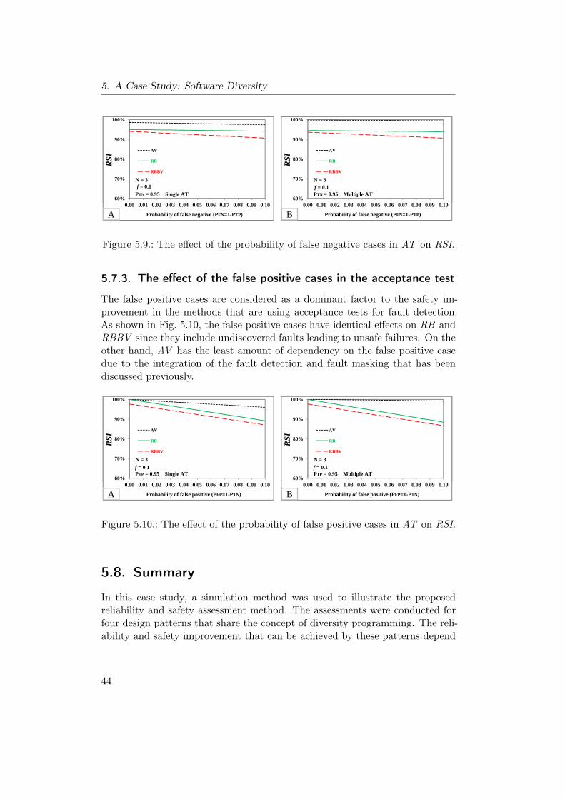
5. A Case Study: Software Diversity
60%
70%
80%
90%
100%
AV
RB
RBBV
f = 0.1PTN = 0.95 Single AT
N = 3
RSI
60%
70%
80%
90%
100%
AV
RB
RBBV
f = 0.1PTN = 0.95 Multiple AT
N = 3
RSI
60%
70%
80%
90%
100%
0.00 0.01 0.02 0.03 0.04 0.05 0.06 0.07 0.08 0.09 0.10
AV
RB
RBBV
f = 0.1PTN = 0.95 Single AT
N = 3
Probability of false negative (PFN=1-PTP)
RSI
A
60%
70%
80%
90%
100%
0.00 0.01 0.02 0.03 0.04 0.05 0.06 0.07 0.08 0.09 0.10
AV
RB
RBBV
f = 0.1PTN = 0.95 Multiple AT
N = 3
Probability of false negative (PFN=1-PTP)
RSI
B
Figure 5.9.: The effect of the probability of false negative cases in AT on RSI.
5.7.3. The effect of the false positive cases in the acceptance test
The false positive cases are considered as a dominant factor to the safety im-provement in the methods that are using acceptance tests for fault detection.As shown in Fig. 5.10, the false positive cases have identical effects on RB andRBBV since they include undiscovered faults leading to unsafe failures. On theother hand, AV has the least amount of dependency on the false positive casedue to the integration of the fault detection and fault masking that has beendiscussed previously.
60%
70%
80%
90%
100%
AV
RB
RBBV
f = 0.1PTP = 0.95 Multiple AT
N = 3
RSI
60%
70%
80%
90%
100%
AV
RB
RBBV
f = 0.1PTP = 0.95 Single AT
N = 3
RSI
60%
70%
80%
90%
100%
0.00 0.01 0.02 0.03 0.04 0.05 0.06 0.07 0.08 0.09 0.10
AV
RB
RBBV
f = 0.1PTP = 0.95 Multiple AT
N = 3
Probability of false positive (PFP=1-PTN)
RSI
B
60%
70%
80%
90%
100%
0.00 0.01 0.02 0.03 0.04 0.05 0.06 0.07 0.08 0.09 0.10
AV
RB
RBBV
f = 0.1PTP = 0.95 Single AT
N = 3
Probability of false positive (PFP=1-PTN)
RSI
A
Figure 5.10.: The effect of the probability of false positive cases in AT on RSI.
5.8. Summary
In this case study, a simulation method was used to illustrate the proposedreliability and safety assessment method. The assessments were conducted forfour design patterns that share the concept of diversity programming. The reli-ability and safety improvement that can be achieved by these patterns depend
44
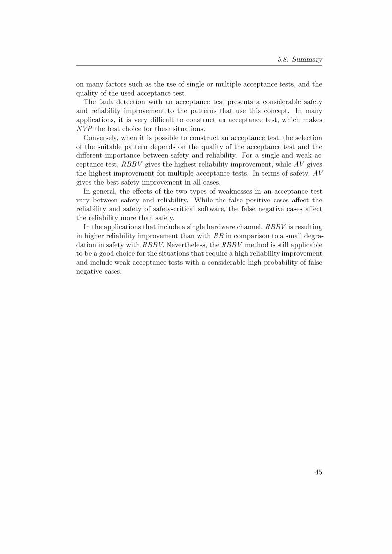
5.8. Summary
on many factors such as the use of single or multiple acceptance tests, and thequality of the used acceptance test.The fault detection with an acceptance test presents a considerable safety
and reliability improvement to the patterns that use this concept. In manyapplications, it is very difficult to construct an acceptance test, which makesNVP the best choice for these situations.Conversely, when it is possible to construct an acceptance test, the selection
of the suitable pattern depends on the quality of the acceptance test and thedifferent importance between safety and reliability. For a single and weak ac-ceptance test, RBBV gives the highest reliability improvement, while AV givesthe highest improvement for multiple acceptance tests. In terms of safety, AVgives the best safety improvement in all cases.In general, the effects of the two types of weaknesses in an acceptance test
vary between safety and reliability. While the false positive cases affect thereliability and safety of safety-critical software, the false negative cases affectthe reliability more than safety.In the applications that include a single hardware channel, RBBV is resulting
in higher reliability improvement than with RB in comparison to a small degra-dation in safety with RBBV. Nevertheless, the RBBV method is still applicableto be a good choice for the situations that require a high reliability improvementand include weak acceptance tests with a considerable high probability of falsenegative cases.
45

5. A Case Study: Software Diversity
46
6. Catalog of Design Patterns
Since the aim of this thesis is to construct a catalog of design patterns for safety-critical embedded systems, this chapter describes the catalog of design patternstool which is the software version of our catalog. This catalog program is a .Netbased tool that has been developed at the embedded software laboratory withthe help of a diploma student using the C# programming language.Section 6.1 introduces the main features of this catalog, while the description
of the architecture is given in Section 6.2. Next, the data model for the databaseis given in Section 6.3. Section 6.4 and 6.5 present the main application guide-lines and the decision support provided in this tool. Section 6.6 describes theimplementation of the developed tool. Finally, the general components and thecatalog structure are described in Section 6.7 and 6.8 respectively.
6.1. Features
In order to achieve the intended goals and requirements of this research, thecatalog software provides the following features:
• An organized collection of design patterns stored in a database.
• Easy to use, install and remove.
• Providing two efficient pattern-retrieval methods:– PDF Viewer which provides a PDF copy of the intended pattern
ready for printing.– An interactive browsing which makes it possible to navigate through
contents of a pattern.
• Providing decision support to users for selecting a suitable pattern for theintended application by including an oriented search mechanism.
• Giving users the capability to create new design patterns.
• Giving users the capability to modify and update the current collectionof patterns or the decision support components.
• Including an additional reliability and safety simulator for the patternsthat are based on the principle of diverse programming.
47
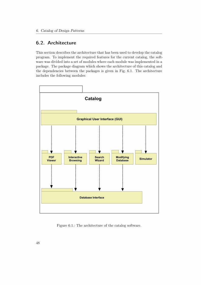
6. Catalog of Design Patterns
6.2. Architecture
This section describes the architecture that has been used to develop the catalogprogram. To implement the required features for the current catalog, the soft-ware was divided into a set of modules where each module was implemented in apackage. The package diagram which shows the architecture of this catalog andthe dependencies between the packages is given in Fig. 6.1. The architectureincludes the following modules:
Graphical User Interface (GUI)
InteractiveBrowsing
SearchWizard
ModifyingDatabase
SimulatorPDFViewer
Database Interface
Catalog
Figure 6.1.: The architecture of the catalog software.
48
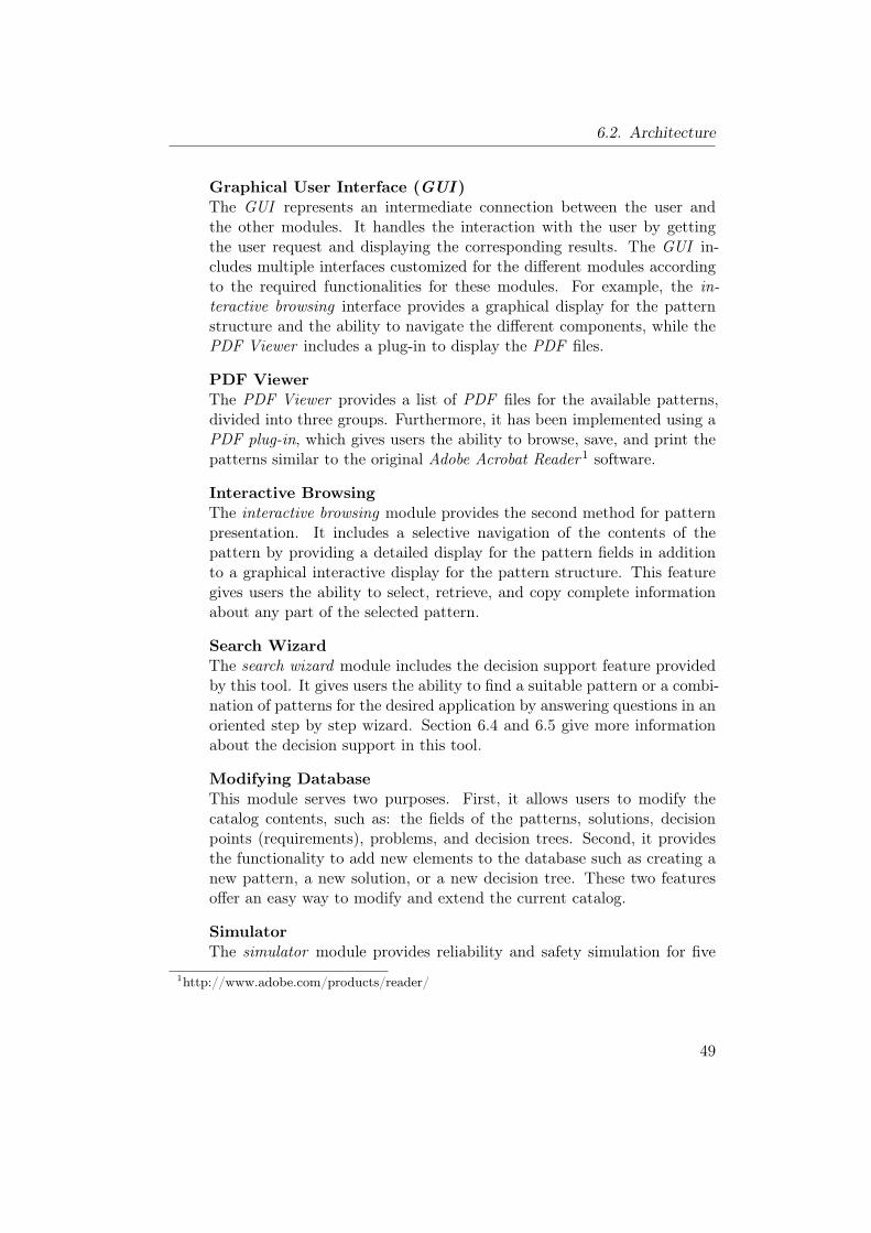
6.2. Architecture
Graphical User Interface (GUI )The GUI represents an intermediate connection between the user andthe other modules. It handles the interaction with the user by gettingthe user request and displaying the corresponding results. The GUI in-cludes multiple interfaces customized for the different modules accordingto the required functionalities for these modules. For example, the in-teractive browsing interface provides a graphical display for the patternstructure and the ability to navigate the different components, while thePDF Viewer includes a plug-in to display the PDF files.
PDF ViewerThe PDF Viewer provides a list of PDF files for the available patterns,divided into three groups. Furthermore, it has been implemented using aPDF plug-in, which gives users the ability to browse, save, and print thepatterns similar to the original Adobe Acrobat Reader1 software.
Interactive BrowsingThe interactive browsing module provides the second method for patternpresentation. It includes a selective navigation of the contents of thepattern by providing a detailed display for the pattern fields in additionto a graphical interactive display for the pattern structure. This featuregives users the ability to select, retrieve, and copy complete informationabout any part of the selected pattern.
Search WizardThe search wizard module includes the decision support feature providedby this tool. It gives users the ability to find a suitable pattern or a combi-nation of patterns for the desired application by answering questions in anoriented step by step wizard. Section 6.4 and 6.5 give more informationabout the decision support in this tool.
Modifying DatabaseThis module serves two purposes. First, it allows users to modify thecatalog contents, such as: the fields of the patterns, solutions, decisionpoints (requirements), problems, and decision trees. Second, it providesthe functionality to add new elements to the database such as creating anew pattern, a new solution, or a new decision tree. These two featuresoffer an easy way to modify and extend the current catalog.
SimulatorThe simulator module provides reliability and safety simulation for five
1http://www.adobe.com/products/reader/
49
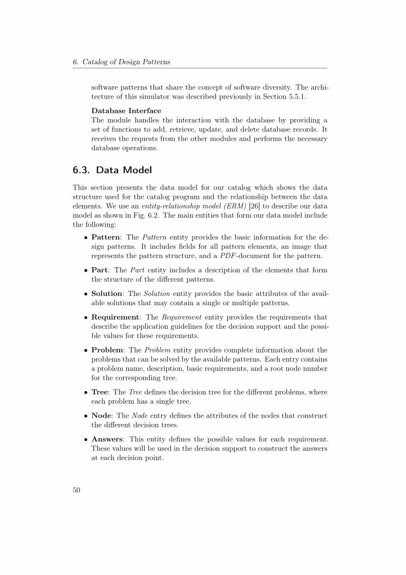
6. Catalog of Design Patterns
software patterns that share the concept of software diversity. The archi-tecture of this simulator was described previously in Section 5.5.1.
Database InterfaceThe module handles the interaction with the database by providing aset of functions to add, retrieve, update, and delete database records. Itreceives the requests from the other modules and performs the necessarydatabase operations.
6.3. Data Model
This section presents the data model for our catalog which shows the datastructure used for the catalog program and the relationship between the dataelements. We use an entity-relationship model (ERM) [26] to describe our datamodel as shown in Fig. 6.2. The main entities that form our data model includethe following:
• Pattern: The Pattern entity provides the basic information for the de-sign patterns. It includes fields for all pattern elements, an image thatrepresents the pattern structure, and a PDF -document for the pattern.
• Part: The Part entity includes a description of the elements that formthe structure of the different patterns.
• Solution: The Solution entity provides the basic attributes of the avail-able solutions that may contain a single or multiple patterns.
• Requirement: The Requirement entity provides the requirements thatdescribe the application guidelines for the decision support and the possi-ble values for these requirements.
• Problem: The Problem entity provides complete information about theproblems that can be solved by the available patterns. Each entry containsa problem name, description, basic requirements, and a root node numberfor the corresponding tree.
• Tree: The Tree defines the decision tree for the different problems, whereeach problem has a single tree.
• Node: The Node entry defines the attributes of the nodes that constructthe different decision trees.
• Answers: This entity defines the possible values for each requirement.These values will be used in the decision support to construct the answersat each decision point.
50
6.3. Data Model
Entity Relationship Diagram1
Pattern Part
Solution
Requirement
ProblemTree
Pattern_Part
Solution_Pattern
NodeSolution_Requirement
Answers
Visual Paradigm for UML Standard Edition(RWTH Aachen)
Figure 6.2.: The entity-relationship model for the database.
The main relationships that illustrate the associations between entities are:
• Pattern_Part: The Pattern_Part relationship relates the Pattern en-tity with the Part entity, specifying on which parts a pattern structurehas been made.
• Solution_Pattern: The Solution_Pattern relationship relates the Pat-tern entity with the Solution entity, specifying the patterns that cooperateto form a solution.
51
6. Catalog of Design Patterns
• Solution_Requirement: The Solution_Requirement relationship re-lates the Solution entity with the Requirement entity to show the ap-plication requirements that should be satisfied for a solution.
In addition to the previous major entities and relationships, several minorentities and relationships have been defined to offer some minor functionalitiessuch as the help files, interactive display, and patterns comparison.
6.4. Application Guidelines
The purpose of the decision support in our catalog, which will be discussed in thenext section, is to present advices to users on how to select a suitable solutionfor a given design problem in the field of safety-critical embedded systems. Thisprocess requires the use of guidelines and decision points that characterize thesituations in which the available patterns are appropriate.In this context, the non-functional requirements for patterns, the limitations
on the available resources, and the intended application requirements are usedas decision points and guidelines for the selection process. For simplicity andto unify the notations for these guidelines, we called them requirements.In the current version of the catalog software, we have fifteen requirements
that are used in the search wizard. These requirements are:
1. Hardware Redundancy: Is it possible to provide multiple hardwarechannels?
2. Software Diversity: Is it possible to provide diverse software versions?
3. Hardware Diversity: Is it possible to provide heterogeneous hardwarechannels?
4. Number of Hardware Channels: The number of hardware channelswhich can be provided.
5. Availability: Investigates whether low or high level of availability isneeded.
6. Fail-Safe State: Is there a reachable state that can be considered to besafe in the case of failure?
7. Sequence Monitoring: Is it necessary to provide a sequence monitor-ing?
8. Acceptance Test: Is it possible to construct an acceptance test to beused in conjunction with the software diversity?
52
6.5. Decision Support
9. Quality of Acceptance Test: Investigate whether the possible accep-tance test can be effective or weak.
10. Reliability Enhancement: Is there a need for a reliability enhance-ment?
11. Reliability vs. Safety: Which non-functional requirement is more im-portant: reliability or safety?
12. Level of Safety Coverage: Which level of safety coverage is needed:low, medium or high?
13. Centralized Monitoring: Is it necessary to provide a centralized moni-toring and complex safety measures?
14. Direct Safety Monitoring: Is it necessary to provide direct safety mon-itoring?
15. Fail-Safe Monitoring and Sequence Monitoring: Is it necessary toprovide a fail-safe state and sequence monitoring?
6.5. Decision Support
The users of the catalog of design patters might find the selection of a suitablepattern that solves a particular design problem, to be a hard process. Therefore,a systematic method, dedicated to help users, should be provided to ease theburden of decision making.Our proposed solution for this difficulty is to develop a decision support sys-
tem as a search wizard in our catalog. This approach involves three principles:
1. Providing the possible combinations of patterns as a set of solutions.
2. Grouping these solutions based on the problems that can be solved.
3. Providing a decision tree for each design problem.
6.5.1. Design Solutions
The pattern template, which has been presented in Section 3.4, provides afield for the related patterns that can be combined with the pattern underconsideration to deal with related problems.Instead of providing discrete patterns, the decision support in our catalog
tool defines 33 solutions for the different problems, where each solution canrepresent:
53
6. Catalog of Design Patterns
• A single pattern solution like in Triple Modular Redundancy or SanityCheck Pattern.
• Multiple patterns solution, which contains a combination of closely relatedpatterns like in Recovery Block with Watchdog.
6.5.2. Design Problems
In this tool, we have grouped the available solutions based on the design prob-lems that can be solved by these solutions. The search wizard module providessolutions for the following problems:
• A General Design Problem: How to design a safety-critical embeddedsystem.
• Six Particular Problems:
– Transient Faults: How to deal with transient faults, to providesome level of safety and reliability to the embedded system in aninexpensive manner.
– Hardware Random Faults: How to deal with hardware randomfaults and single-point of failure.
– Hardware Systematic Faults: How to deal with hardware system-atic faults.
– Safety Monitoring : How to improve system safety through safetymonitoring in the presence of a single point of failure.
– Time Base Faults (Sequence Monitoring): How to identifytime base faults by sequence monitoring.
– Software Faults: How to provide highly reliable fault-tolerant soft-ware for a highly safety-critical system.
6.5.3. Decision Trees
Each of the previously listed problems contains a set of applicable solutions,where each solution has its own requirements. In order to provide an orientedstep-by-step approach that would lead the users through the process of solutionselection, the solutions and their requirements are structured as decision trees,where each problem has its own decision tree. Fig. 6.3 shows the decision treefor a specific problem (Safety Monitoring), while a listing of all the decisiontrees can be found in Appendix A.In each decision tree, the external nodes (leaves) contain the applicable so-
lutions for the represented problem, and the internal nodes contain decision
54
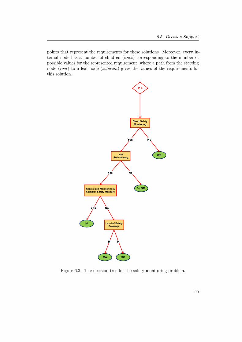
6.5. Decision Support
points that represent the requirements for these solutions. Moreover, every in-ternal node has a number of children (links) corresponding to the number ofpossible values for the represented requirement, where a path from the startingnode (root) to a leaf node (solution) gives the values of the requirements forthis solution.
Direct Safety
Monitoring
P 4
Yes No
WDHW
Redundancy
No
Level of Safety
CoverageSE
Yes
SCMA
H M
NoYes
Centralized Monitoring &
Complex Safety Measure
3-LSM
Figure 6.3.: The decision tree for the safety monitoring problem.
55
6. Catalog of Design Patterns
One of the main advantages of this approach is that the information containedin a decision tree is stored in a database, which makes the search programindependent of the represented problems, requirements, and solutions. Thisfeature eases the modification and extension of the decision support module toinclude: new patterns, solutions, problem, or decision trees without affectingthe search program.The search procedure for a given problem is conducted as an oriented se-
quence of questions to be answered by the user. It starts from the root node byconstructing a question for the represented requirement, and then it providesthe possible answers for this decision node. Normally, the user selects one ofthe possible answers, which will be checked by the procedure to determine thesuitable child node for the next question. This process is repeated until thesearch procedure reaches a leaf node which is immediately selected to be an ex-pected solution for the given problem. This answer represents the best availablesolution based on the requirements provided by the user, which implies that itis not the absolute best solution for this problem.The search procedure gives the user the possibility to relax some requirements
by providing a “don’t care” answer. In this situation, when the user relaxes arequirement at a decision node, the search procedure takes all the possibleanswers for this requirement into consideration by traversing all the out-goingpaths from this node.The relaxation of some requirements during the search procedure might lead
to multiple applicable solutions for the given problem. Therefore, the searchprocedure provides a comparison between the resulted solutions as a report.This report shows the applicable solutions as well as the requirements values ofthese solutions.Note that the search procedure for a problem does not use all the existing
requirements for two reasons: First, there are some requirements that are notrelated to the problem under consideration. Second, there are some basic defaultrequirements that should be provided in all cases to solve a problem; like thesoftware diversity for software faults handling, and the hardware redundancy forsystematic faults handling. Therefore, the decision trees, which are providedin the decision support, include an organized minimal set of requirements todistinguish between the applicable solutions for each problem.Summarizing, the developed search procedure aims to provide a simple de-
cision support method that assists users in selecting a suitable pattern or acombination of related patterns to solve a particular problem with certain re-quirements. The representations of the existing patterns, requirements, prob-lems, solutions, and relationships between these entities, as presented in ourapproach, facilitate this decision support. Furthermore, they increase the levelof independence between the developed tool and the available patterns, which al-
56
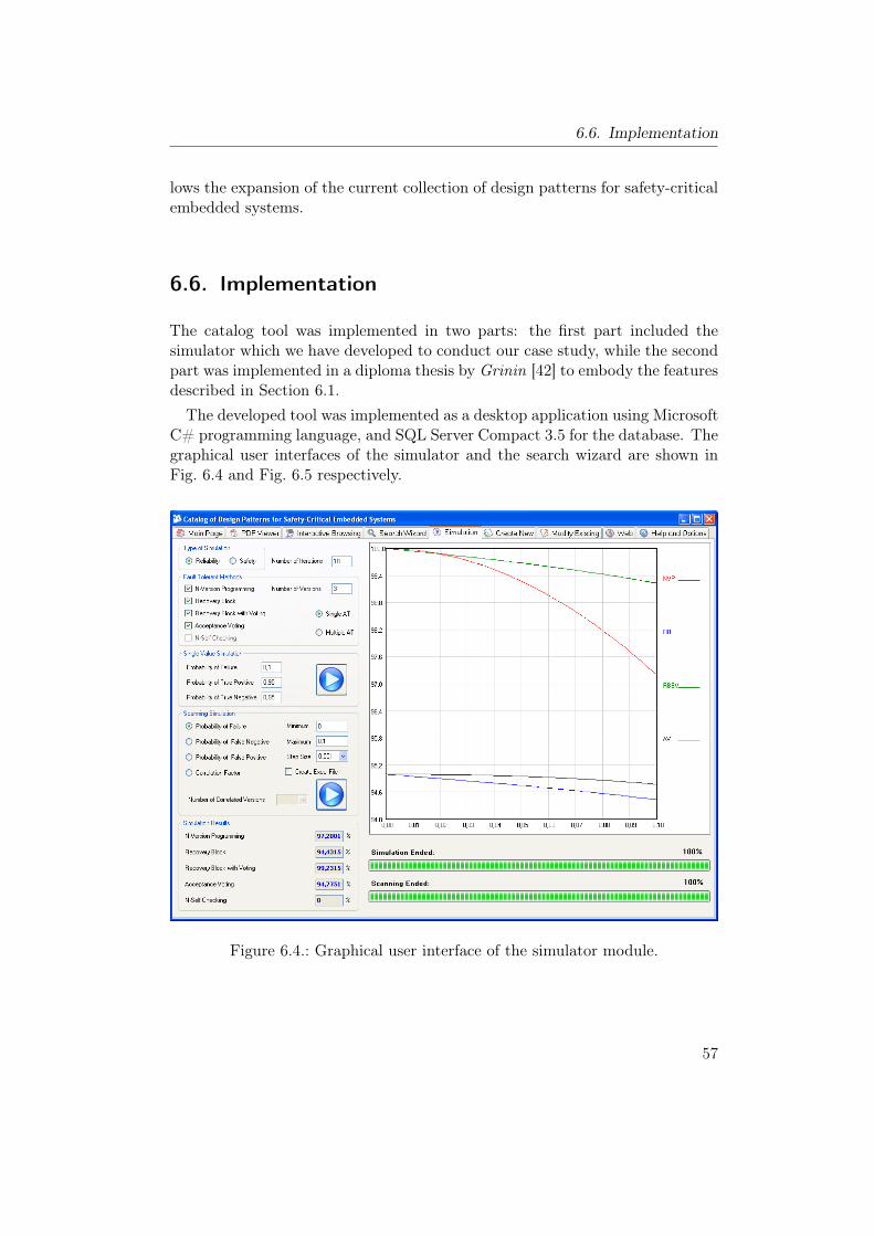
6.6. Implementation
lows the expansion of the current collection of design patterns for safety-criticalembedded systems.
6.6. Implementation
The catalog tool was implemented in two parts: the first part included thesimulator which we have developed to conduct our case study, while the secondpart was implemented in a diploma thesis by Grinin [42] to embody the featuresdescribed in Section 6.1.The developed tool was implemented as a desktop application using Microsoft
C# programming language, and SQL Server Compact 3.5 for the database. Thegraphical user interfaces of the simulator and the search wizard are shown inFig. 6.4 and Fig. 6.5 respectively.
Figure 6.4.: Graphical user interface of the simulator module.
57
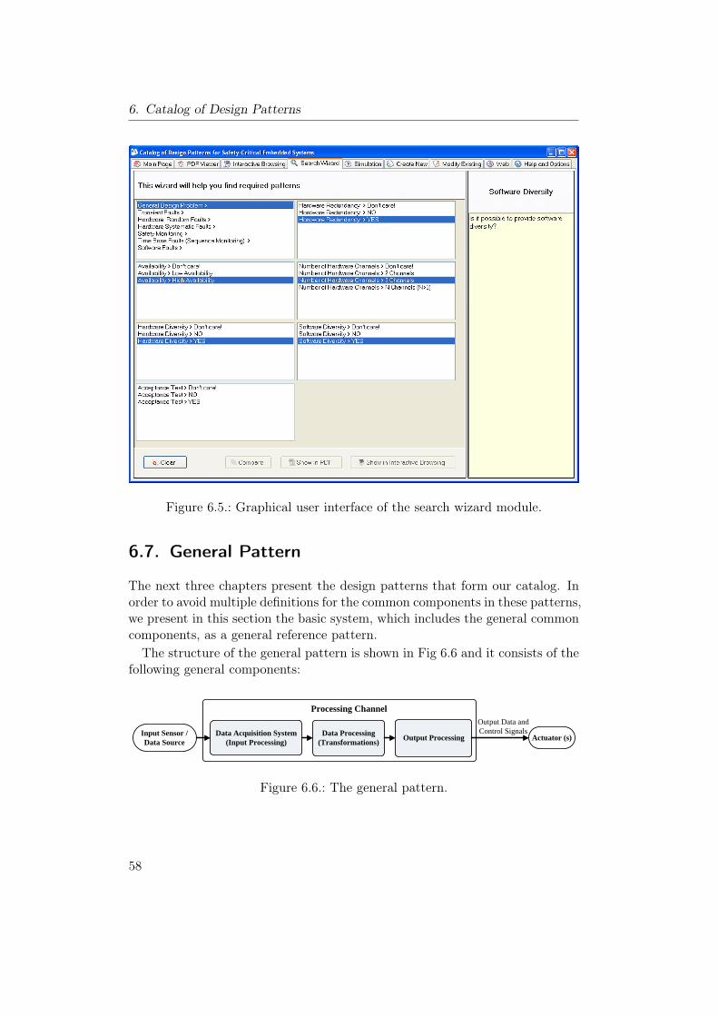
6. Catalog of Design Patterns
Figure 6.5.: Graphical user interface of the search wizard module.
6.7. General Pattern
The next three chapters present the design patterns that form our catalog. Inorder to avoid multiple definitions for the common components in these patterns,we present in this section the basic system, which includes the general commoncomponents, as a general reference pattern.The structure of the general pattern is shown in Fig 6.6 and it consists of the
following general components:
Actuator (s)Data Acquisition System (Input Processing)
Data Processing (Transformations) Output Processing Input Sensor /
Data Source
Processing ChannelOutput Data andControl Signals
Figure 6.6.: The general pattern.
58
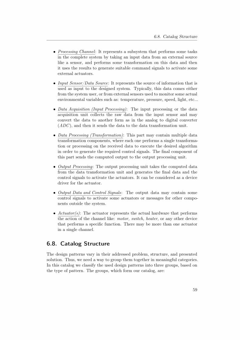
6.8. Catalog Structure
• Processing Channel : It represents a subsystem that performs some tasksin the complete system by taking an input data from an external sourcelike a sensor, and performs some transformation on this data and thenit uses the results to generate suitable command signals to activate someexternal actuators.
• Input Sensor/Data Source: It represents the source of information that isused as input to the designed system. Typically, this data comes eitherfrom the system user, or from external sensors used to monitor some actualenvironmental variables such as: temperature, pressure, speed, light, etc...
• Data Acquisition (Input Processing): The input processing or the dataacquisition unit collects the raw data from the input sensor and mayconvert the data to another form as in the analog to digital converter(ADC ), and then it sends the data to the data transformation unit.
• Data Processing (Transformation): This part may contain multiple datatransformation components, where each one performs a single transforma-tion or processing on the received data to execute the desired algorithmin order to generate the required control signals. The final component ofthis part sends the computed output to the output processing unit.
• Output Processing : The output processing unit takes the computed datafrom the data transformation unit and generates the final data and thecontrol signals to activate the actuators. It can be considered as a devicedriver for the actuator.
• Output Data and Control Signals: The output data may contain somecontrol signals to activate some actuators or messages for other compo-nents outside the system.
• Actuator(s): The actuator represents the actual hardware that performsthe action of the channel like: motor, switch, heater, or any other devicethat performs a specific function. There may be more than one actuatorin a single channel.
6.8. Catalog Structure
The design patterns vary in their addressed problem, structure, and presentedsolution. Thus, we need a way to group them together in meaningful categories.In this catalog we classify the used design patterns into three groups, based onthe type of pattern. The groups, which form our catalog, are:
59
6. Catalog of Design Patterns
• Hardware Patterns: Includes the patterns that contain explicit hard-ware redundancy to improve either reliability or safety. This group con-tains the following 8 patterns:
– Homogeneous Duplex Pattern. (Section 7.3)
– Heterogeneous Duplex Pattern. (Section 7.4)
– Triple Modular Redundancy Pattern. (Section 7.5)
– M-Out-Of-N Pattern. (Section 7.6)
– Monitor-Actuator Pattern. (Section 7.7)
– Sanity Check Pattern. (Section 7.8)
– Watchdog Pattern. (Section 7.9)
– Safety Executive Pattern. (Section 7.10)
• Software Patterns: Includes the patterns that use software diversity(software redundancy) to tolerate software faults. This group containsthe following 5 patterns:
– N-Version Programming Pattern. (Section 8.5)
– Recovery Block Pattern. (Section 8.6)
– Acceptance Voting Pattern. (Section 8.7)
– N-Self Checking Programming Pattern. (Section 8.8)
– Recovery Block with Backup Voting Pattern. (Section 8.9)
• Combination of Hardware and Software Patterns: Include 2 pat-terns that do not contain explicit hardware redundancy or software diver-sity:
– Protected Single Channel Pattern. (Section 9.1)
– 3-Level Safety Monitoring Pattern. (Section 9.2)
Clearly, there are many ways to categorize design patterns. For our purpose,it will be sufficient to use this structure, since it groups the patterns that addressrelated problems and use related concepts.
60
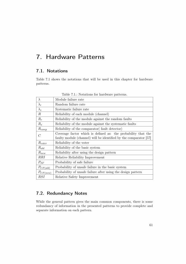
7. Hardware Patterns
7.1. Notations
Table 7.1 shows the notations that will be used in this chapter for hardwarepatterns.
Table 7.1.: Notations for hardware patterns.λ Module failure rateλr Random failure rateλs Systematic failure rateR Reliability of each module (channel)Rr Reliability of the module against the random faultsRs Reliability of the module against the systematic faultsRcomp Reliability of the comparator( fault detector)
CCoverage factor which is defined as: the probability that thefaulty module (channel) will be identified by the comparator [57]
Rvoter Reliability of the voterRold Reliability of the basic systemRnew Reliability after using the design patternRRI Relative Reliability ImprovementPSF Probability of safe failurePUF (old) Probability of unsafe failure in the basic systemPUF (new) Probability of unsafe failure after using the design patternRSI Relative Safety Improvement
7.2. Redundancy Notes
While the general pattern gives the main common components, there is someredundancy of information in the presented patterns to provide complete andseparate information on each pattern.
61
7. Hardware Patterns
7.3. Homogeneous Duplex Pattern (HmD)
Other Names:Homogeneous Redundancy Pattern [37], Standby-Spare Pattern, Dynamic Re-dundancy Pattern, Two-Channel Redundancy Pattern [44].
Type:Hardware Pattern.
Abstract:It is a hardware pattern that is used to increase the safety and reliability of thesystem by providing a replication of the same module (Modular redundancy)to deal with the random faults. The Homogeneous Duplex Pattern consists oftwo identical modules (channels); The primary (active) module and secondary(standby) module. This pattern can be applied to any level in the system de-sign from a complete system (channel) to a single component. The idea of thispattern is based on the assumption that it is highly unlikely for two identicalcomponents to suffer a random fault simultaneously.
Context:Developing an embedded system with no fail-safe-state in a situation that in-cludes:– High random failure rate and low systematic failure rate.– There is a possibility to identify the faults that may lead to a system failure.– High level of redundancy such as triple modular redundancy is not applicable.
Problem:How to deal with random faults and how to make the system continue operatingin the presence of a fault in one of the system components, in order to increasethe safety and reliability of the system.
Pattern Structure:The general structure for this pattern is shown in Fig. 7.1. This pattern can beapplied to different levels: from a single component to a complete subsystem(channel). Generally, it consists of two identical modules; a primary (active)module and secondary (standby), and there is a fault detection unit that mon-itors the primary module and switches to the secondary module when a faultappears in the primary.The function of each unit is as follows:
• Module (Channel): (see the general pattern in Section 6.7).
62
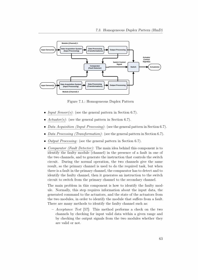
7.3. Homogeneous Duplex Pattern (HmD)
Actuator(s)
Data Acquisition System (Input Processing)
Data Processing (Transformations) Output Processing Input Sensor(s)
Comparator (Fault Detector)
Data Acquisition System (Input Processing)
Data Processing (Transformations) Output Processing Input Sensor(s)
Switch
Module (Channel) 1
Module (Channel) 2
Switch Control Signal
Actuator Control
Signal(s)
Figure 7.1.: Homogeneous Duplex Pattern
• Input Sensor(s): (see the general pattern in Section 6.7).
• Actuator(s): (see the general pattern in Section 6.7).
• Data Acquisition (Input Processing): (see the general pattern in Section 6.7).
• Data Processing (Transformation): (see the general pattern in Section 6.7).
• Output Processing : (see the general pattern in Section 6.7).
• Comparator (Fault Detector): The main idea behind this component is toidentify the faulty module (channel) in the presence of a fault in one ofthe two channels, and to generate the instruction that controls the switchcircuit. During the normal operation, the two channels give the sameresult, so the primary channel is used to do the required task, but whenthere is a fault in the primary channel, the comparator has to detect and toidentify the faulty channel, then it generates an instruction to the switchcircuit to switch from the primary channel to the secondary channel.
The main problem in this component is how to identify the faulty mod-ule. Normally, this step requires information about the input data, thegenerated command to the actuators, and the state of the actuators fromthe two modules, in order to identify the module that suffers from a fault.There are many methods to identify the faulty channel such as:
– Acceptance Test [57]: This method performs a check on the twochannels by checking for input valid data within a given range andby checking the output signals from the two modules whether theyare valid or not.
63
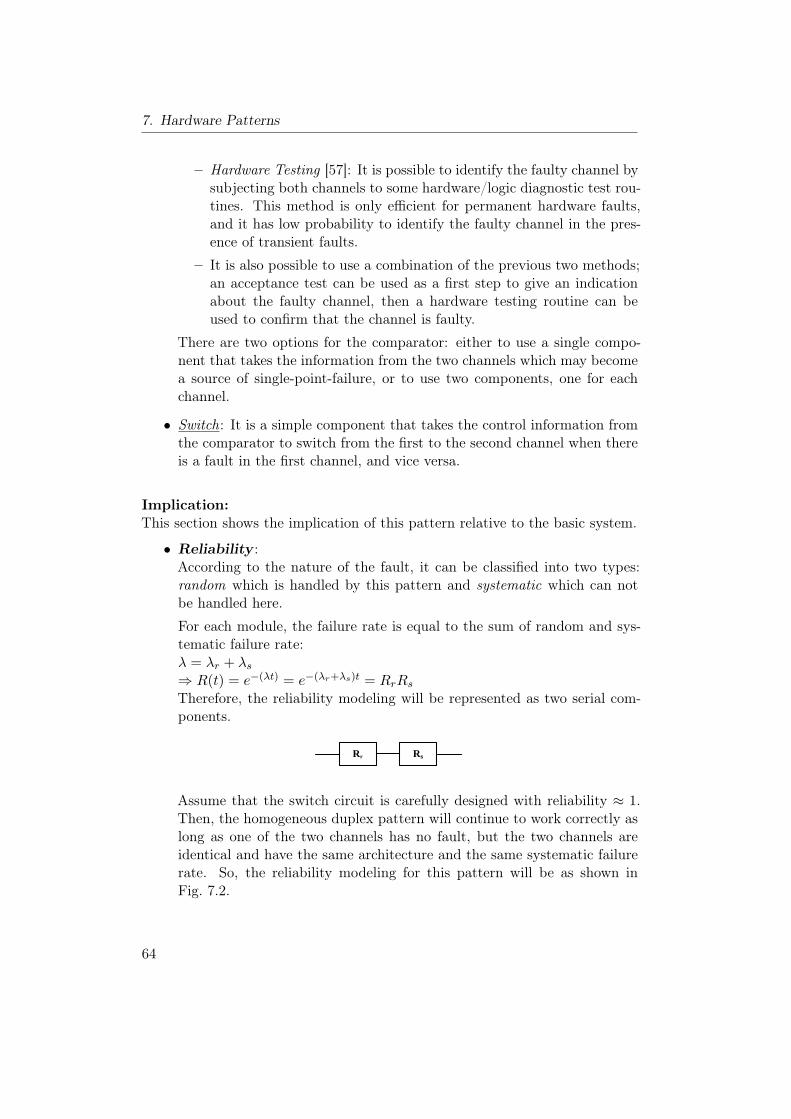
7. Hardware Patterns
– Hardware Testing [57]: It is possible to identify the faulty channel bysubjecting both channels to some hardware/logic diagnostic test rou-tines. This method is only efficient for permanent hardware faults,and it has low probability to identify the faulty channel in the pres-ence of transient faults.
– It is also possible to use a combination of the previous two methods;an acceptance test can be used as a first step to give an indicationabout the faulty channel, then a hardware testing routine can beused to confirm that the channel is faulty.
There are two options for the comparator: either to use a single compo-nent that takes the information from the two channels which may becomea source of single-point-failure, or to use two components, one for eachchannel.
• Switch: It is a simple component that takes the control information fromthe comparator to switch from the first to the second channel when thereis a fault in the first channel, and vice versa.
Implication:This section shows the implication of this pattern relative to the basic system.
• Reliability :According to the nature of the fault, it can be classified into two types:random which is handled by this pattern and systematic which can notbe handled here.
For each module, the failure rate is equal to the sum of random and sys-tematic failure rate:λ = λr + λs⇒ R(t) = e−(λt) = e−(λr+λs)t = RrRsTherefore, the reliability modeling will be represented as two serial com-ponents.
Rr Rs
Rr
Rs
Rr
Rcomp
Assume that the switch circuit is carefully designed with reliability ≈ 1.Then, the homogeneous duplex pattern will continue to work correctly aslong as one of the two channels has no fault, but the two channels areidentical and have the same architecture and the same systematic failurerate. So, the reliability modeling for this pattern will be as shown inFig. 7.2.
64
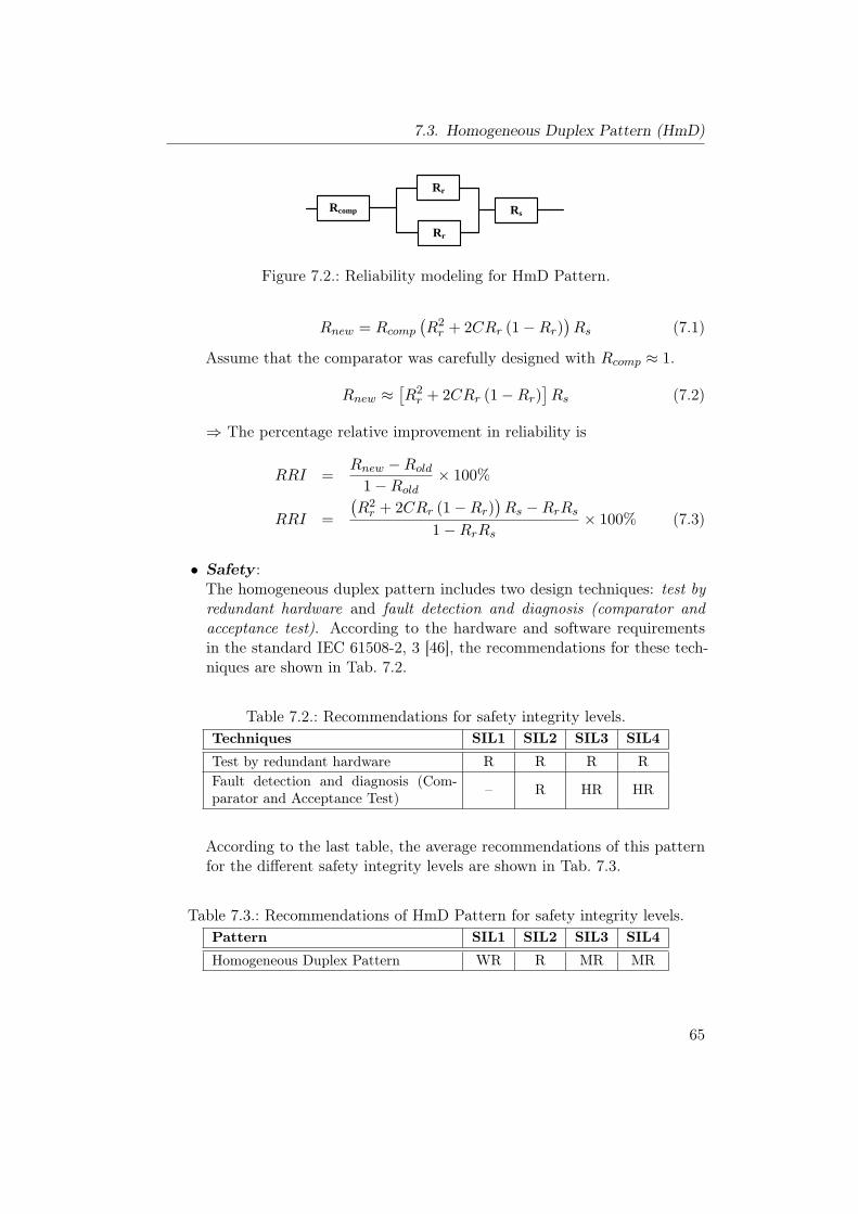
7.3. Homogeneous Duplex Pattern (HmD)
Rr Rs
Rr
Rs
Rr
Rcomp
Figure 7.2.: Reliability modeling for HmD Pattern.
Rnew = Rcomp(R2r + 2CRr (1−Rr)
)Rs (7.1)
Assume that the comparator was carefully designed with Rcomp ≈ 1.
Rnew ≈[R2r + 2CRr (1−Rr)
]Rs (7.2)
⇒ The percentage relative improvement in reliability is
RRI =Rnew −Rold
1−Rold× 100%
RRI =
(R2r + 2CRr (1−Rr)
)Rs −RrRs
1−RrRs× 100% (7.3)
• Safety :The homogeneous duplex pattern includes two design techniques: test byredundant hardware and fault detection and diagnosis (comparator andacceptance test). According to the hardware and software requirementsin the standard IEC 61508-2, 3 [46], the recommendations for these tech-niques are shown in Tab. 7.2.
Table 7.2.: Recommendations for safety integrity levels.Techniques SIL1 SIL2 SIL3 SIL4
Test by redundant hardware R R R RFault detection and diagnosis (Com-parator and Acceptance Test) – R HR HR
According to the last table, the average recommendations of this patternfor the different safety integrity levels are shown in Tab. 7.3.
Table 7.3.: Recommendations of HmD Pattern for safety integrity levels.Pattern SIL1 SIL2 SIL3 SIL4
Homogeneous Duplex Pattern WR R MR MR
65
7. Hardware Patterns
To compute RSI:
PUF (old) = 1−R = 1−RrRs (7.4)
The probability that the system will give an erroneous result that leadsto unsafe failure is
PUF (new) = 1−Rnew = 1−Rcomp(R2r + 2CRr (1−Rr)
)Rs (7.5)
⇒ The percentage relative safety improvement is
RSI =PUF (new) − PUF (old)
0− PUF (old)× 100%
RSI =
(1−Rcomp
(R2r + 2CRr (1−Rr)
)Rs)− (1−RrRs)
0− (1−RrRs)× 100%
RSI =Rcomp
(R2r + 2CRr (1−Rr)
)Rs −RrRs
1−RrRs× 100% (7.6)
Under the assumption that the comparator was carefully designed withRcomp ≈ 1.
RSI =
(R2r + 2CRr (1−Rr)
)Rs −RrRs
1−RrRs× 100% (7.7)
It is clear from Equation (7.7) and Equation (7.3) that the relative safetyimprovement is equal to the relative reliability improvement.
• Cost:The cost of this pattern can be classified into two parts:
– Recurring Cost :
∗ Since there are two identical channels, then the recurring costwill be increased by 200% comparing to the basic module.
∗ The recurring cost will also include the cost of the comparatorand fault detector component which depends on the type of im-plementation, in addition to the cost of the switch circuit.
– Development Cost : The development cost for the two modules (chan-nels) is equivalent to the development cost of a single channel, be-cause they are identical.
• Modifiability :In general, the level of modifiability of this pattern is similar to the basicsystem (single channel) since it consists of two identical channels. The only
66
7.3. Homogeneous Duplex Pattern (HmD)
difference exists in the comparator and fault detector. If it is requiredto modify the system, then the designer should take this modificationinto consideration and the comparator should be modified to use the newinformation in the fault detection process.
• Impact on Execution Time:During the normal operation without faults, if the comparator circuit wasimplemented as a hardware circuit that is running in parallel with thetwo channels, then there is no change in the time of execution. But if thiscomponent includes software acceptance test, then the time of executionwill be affected by the time needed to execute this test. In the presence ofa fault, the execution time will depend on the speed of fault detection andthe required time to replace the active channel with the standby channel.
Implementation:
• To implement this pattern, the computational channel should be dupli-cated as well as the other devices should be also duplicated.
• The comparator and fault detector component should be carefully de-signed to get a high coverage rate.
• Based on the state of the standby spare module, there are three modes:
1. Hot Redundancy : The primary and the standby modules are workingcontinuously in parallel to provide high reliability. This mode issuitable for application with strict time constraints.
2. Warm Redundancy : The standby spare module runs in idle state andif the comparator and fault detector component detects any fault inthe primary channel, the standby module takes over the load fromthe primary module.
3. Cold Redundancy : In this arrangement, the standby spare moduleis normally off, and when a fault is detected, it will be put intooperation immediately.
• The decision between the previous three arrangements depends on therequired safety level, response time, and the power consumption. Whilehot redundancy has the highest safety level, cold redundancy has the leastamount of power consumption. Thus, cold redundancy is more suitablefor low power applications.
67
7. Hardware Patterns
Consequences and Side Effects:
• The main drawback for this pattern is that it is not appropriate for sys-tematic fault handling, since the two channels are identical and have thesame possible fault. In the case of systematic fault, the switch circuit,that is designed to select between the two channels, will switch to one ofthe two faulty channels, which will lead to a complete system failure.
• When a fault is detected in the primary channel, the switch circuit switchesover to the secondary channel which may include a loss of a computationstep and may include a loss of input data, especially if there is no recoverytime to redo the computation [37].
Related Patterns:
• As described previously, the main problem for this pattern is the system-atic faults. So, it is possible to use heterogeneous duplex pattern which issimilar to this pattern except in using heterogeneous modules (channels)instead of identical modules.
• To increase the safety and reliability of the system it is possible to usemore than one spare channel which makes the pattern more expensive.
68
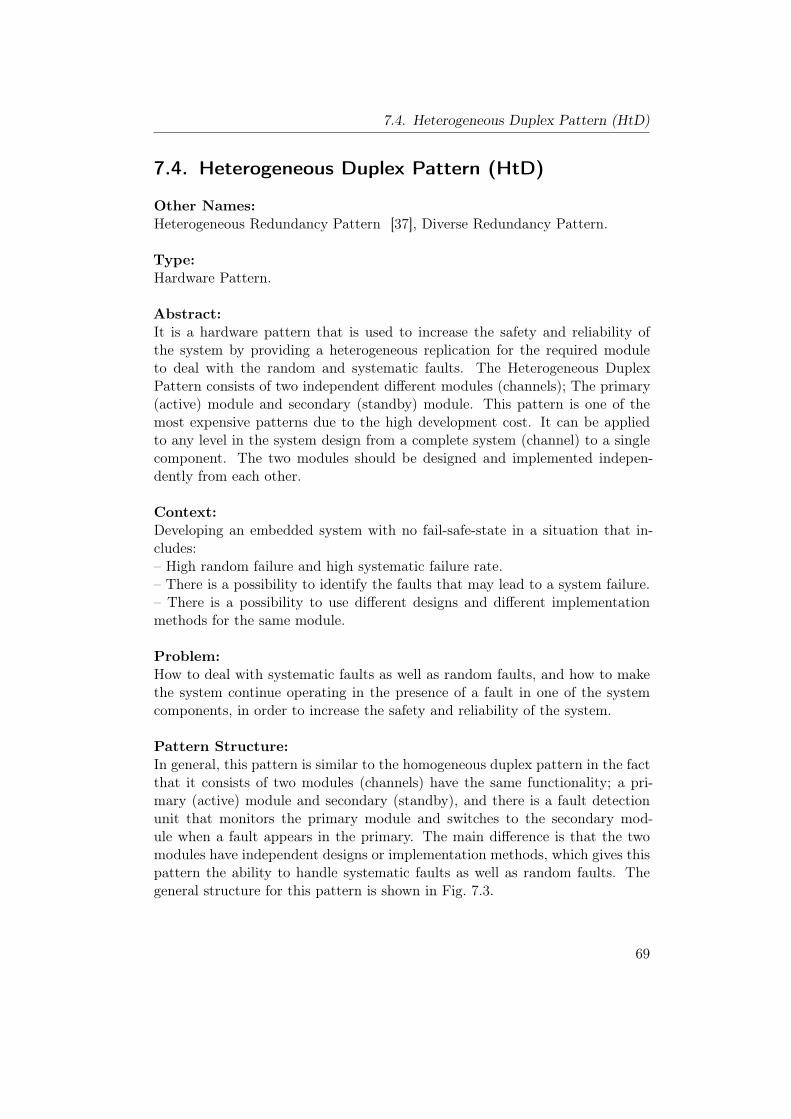
7.4. Heterogeneous Duplex Pattern (HtD)
7.4. Heterogeneous Duplex Pattern (HtD)
Other Names:Heterogeneous Redundancy Pattern [37], Diverse Redundancy Pattern.
Type:Hardware Pattern.
Abstract:It is a hardware pattern that is used to increase the safety and reliability ofthe system by providing a heterogeneous replication for the required moduleto deal with the random and systematic faults. The Heterogeneous DuplexPattern consists of two independent different modules (channels); The primary(active) module and secondary (standby) module. This pattern is one of themost expensive patterns due to the high development cost. It can be appliedto any level in the system design from a complete system (channel) to a singlecomponent. The two modules should be designed and implemented indepen-dently from each other.
Context:Developing an embedded system with no fail-safe-state in a situation that in-cludes:– High random failure and high systematic failure rate.– There is a possibility to identify the faults that may lead to a system failure.– There is a possibility to use different designs and different implementationmethods for the same module.
Problem:How to deal with systematic faults as well as random faults, and how to makethe system continue operating in the presence of a fault in one of the systemcomponents, in order to increase the safety and reliability of the system.
Pattern Structure:In general, this pattern is similar to the homogeneous duplex pattern in the factthat it consists of two modules (channels) have the same functionality; a pri-mary (active) module and secondary (standby), and there is a fault detectionunit that monitors the primary module and switches to the secondary mod-ule when a fault appears in the primary. The main difference is that the twomodules have independent designs or implementation methods, which gives thispattern the ability to handle systematic faults as well as random faults. Thegeneral structure for this pattern is shown in Fig. 7.3.
69
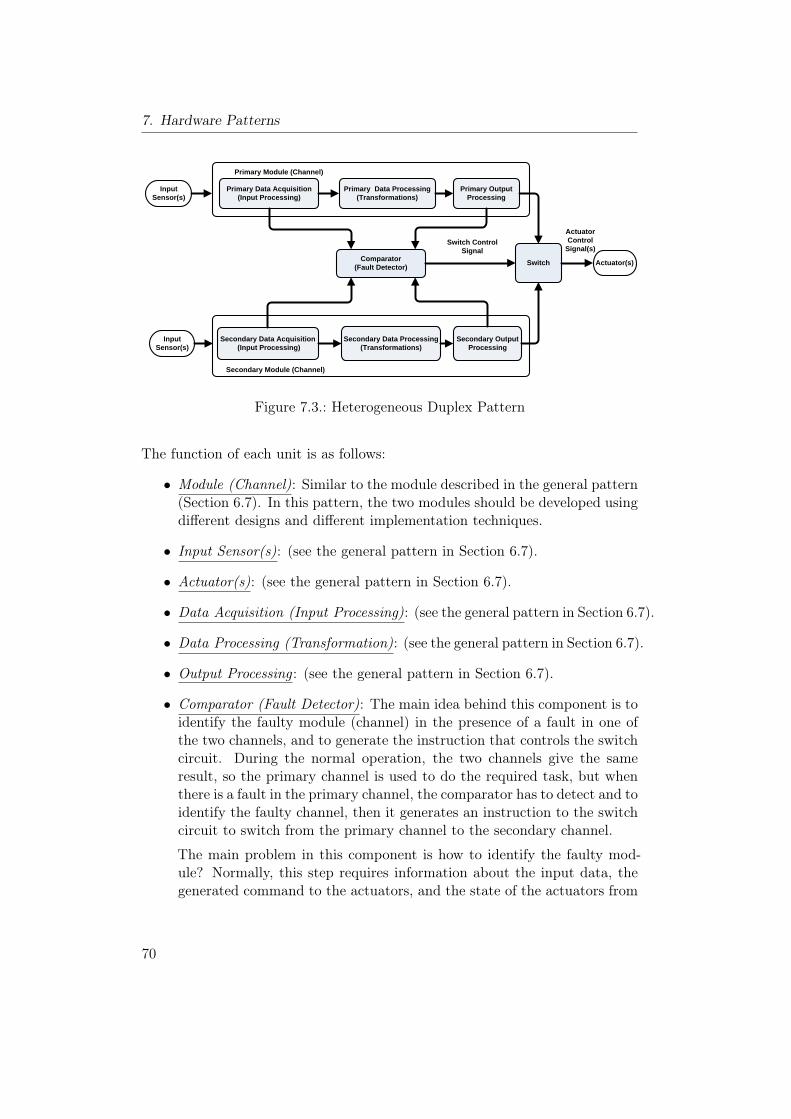
7. Hardware Patterns
Actuator(s)
Primary Data Acquisition(Input Processing)
Primary Data Processing (Transformations)
Primary Output Processing
Input Sensor(s)
Comparator (Fault Detector)
Secondary Data Acquisition (Input Processing)
Secondary Data Processing (Transformations)
Secondary Output Processing
Input Sensor(s)
Switch
Secondary Module (Channel)
Primary Module (Channel)
Actuator Control
Signal(s)Switch Control
Signal
Figure 7.3.: Heterogeneous Duplex Pattern
The function of each unit is as follows:
• Module (Channel): Similar to the module described in the general pattern(Section 6.7). In this pattern, the two modules should be developed usingdifferent designs and different implementation techniques.
• Input Sensor(s): (see the general pattern in Section 6.7).
• Actuator(s): (see the general pattern in Section 6.7).
• Data Acquisition (Input Processing): (see the general pattern in Section 6.7).
• Data Processing (Transformation): (see the general pattern in Section 6.7).
• Output Processing : (see the general pattern in Section 6.7).
• Comparator (Fault Detector): The main idea behind this component is toidentify the faulty module (channel) in the presence of a fault in one ofthe two channels, and to generate the instruction that controls the switchcircuit. During the normal operation, the two channels give the sameresult, so the primary channel is used to do the required task, but whenthere is a fault in the primary channel, the comparator has to detect and toidentify the faulty channel, then it generates an instruction to the switchcircuit to switch from the primary channel to the secondary channel.
The main problem in this component is how to identify the faulty mod-ule? Normally, this step requires information about the input data, thegenerated command to the actuators, and the state of the actuators from
70
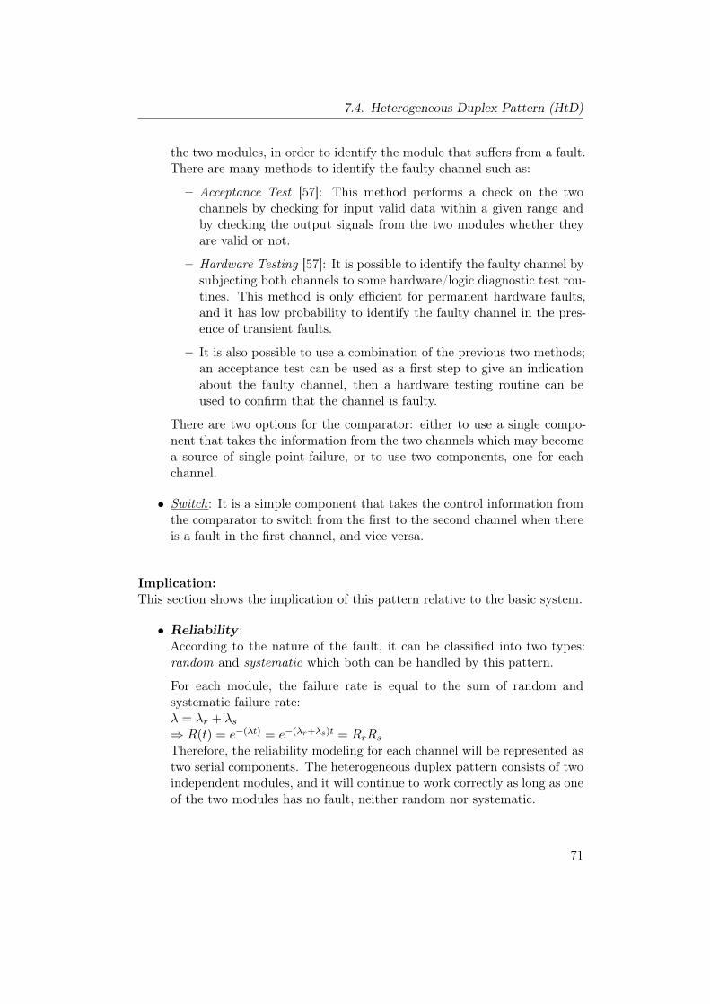
7.4. Heterogeneous Duplex Pattern (HtD)
the two modules, in order to identify the module that suffers from a fault.There are many methods to identify the faulty channel such as:
– Acceptance Test [57]: This method performs a check on the twochannels by checking for input valid data within a given range andby checking the output signals from the two modules whether theyare valid or not.
– Hardware Testing [57]: It is possible to identify the faulty channel bysubjecting both channels to some hardware/logic diagnostic test rou-tines. This method is only efficient for permanent hardware faults,and it has low probability to identify the faulty channel in the pres-ence of transient faults.
– It is also possible to use a combination of the previous two methods;an acceptance test can be used as a first step to give an indicationabout the faulty channel, then a hardware testing routine can beused to confirm that the channel is faulty.
There are two options for the comparator: either to use a single compo-nent that takes the information from the two channels which may becomea source of single-point-failure, or to use two components, one for eachchannel.
• Switch: It is a simple component that takes the control information fromthe comparator to switch from the first to the second channel when thereis a fault in the first channel, and vice versa.
Implication:This section shows the implication of this pattern relative to the basic system.
• Reliability :According to the nature of the fault, it can be classified into two types:random and systematic which both can be handled by this pattern.
For each module, the failure rate is equal to the sum of random andsystematic failure rate:λ = λr + λs⇒ R(t) = e−(λt) = e−(λr+λs)t = RrRsTherefore, the reliability modeling for each channel will be represented astwo serial components. The heterogeneous duplex pattern consists of twoindependent modules, and it will continue to work correctly as long as oneof the two modules has no fault, neither random nor systematic.
71
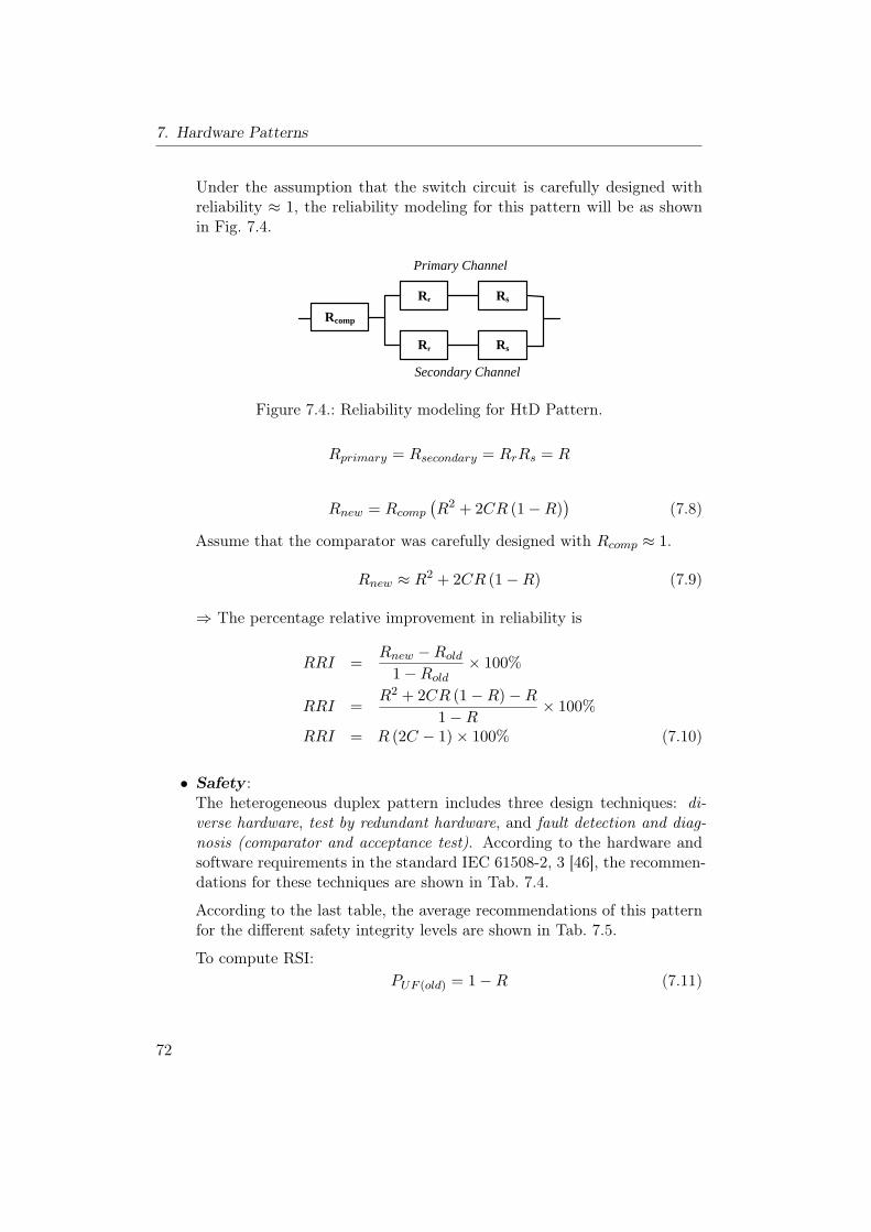
7. Hardware Patterns
Under the assumption that the switch circuit is carefully designed withreliability ≈ 1, the reliability modeling for this pattern will be as shownin Fig. 7.4.
Rr Rs
Rcomp
Rr Rs
Primary Channel
Secondary Channel
Figure 7.4.: Reliability modeling for HtD Pattern.
Rprimary = Rsecondary = RrRs = R
Rnew = Rcomp(R2 + 2CR (1−R)
)(7.8)
Assume that the comparator was carefully designed with Rcomp ≈ 1.
Rnew ≈ R2 + 2CR (1−R) (7.9)
⇒ The percentage relative improvement in reliability is
RRI =Rnew −Rold
1−Rold× 100%
RRI =R2 + 2CR (1−R)−R
1−R× 100%
RRI = R (2C − 1)× 100% (7.10)
• Safety :The heterogeneous duplex pattern includes three design techniques: di-verse hardware, test by redundant hardware, and fault detection and diag-nosis (comparator and acceptance test). According to the hardware andsoftware requirements in the standard IEC 61508-2, 3 [46], the recommen-dations for these techniques are shown in Tab. 7.4.
According to the last table, the average recommendations of this patternfor the different safety integrity levels are shown in Tab. 7.5.
To compute RSI:PUF (old) = 1−R (7.11)
72
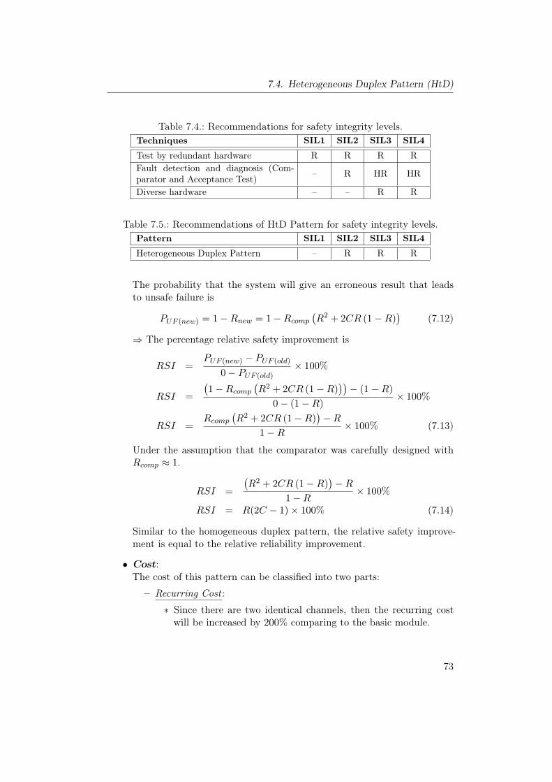
7.4. Heterogeneous Duplex Pattern (HtD)
Table 7.4.: Recommendations for safety integrity levels.Techniques SIL1 SIL2 SIL3 SIL4
Test by redundant hardware R R R RFault detection and diagnosis (Com-parator and Acceptance Test) – R HR HR
Diverse hardware – – R R
Table 7.5.: Recommendations of HtD Pattern for safety integrity levels.Pattern SIL1 SIL2 SIL3 SIL4
Heterogeneous Duplex Pattern – R R R
The probability that the system will give an erroneous result that leadsto unsafe failure is
PUF (new) = 1−Rnew = 1−Rcomp(R2 + 2CR (1−R)
)(7.12)
⇒ The percentage relative safety improvement is
RSI =PUF (new) − PUF (old)
0− PUF (old)× 100%
RSI =
(1−Rcomp
(R2 + 2CR (1−R)
))− (1−R)
0− (1−R)× 100%
RSI =Rcomp
(R2 + 2CR (1−R)
)−R
1−R× 100% (7.13)
Under the assumption that the comparator was carefully designed withRcomp ≈ 1.
RSI =
(R2 + 2CR (1−R)
)−R
1−R× 100%
RSI = R(2C − 1)× 100% (7.14)
Similar to the homogeneous duplex pattern, the relative safety improve-ment is equal to the relative reliability improvement.
• Cost:The cost of this pattern can be classified into two parts:
– Recurring Cost :
∗ Since there are two identical channels, then the recurring costwill be increased by 200% comparing to the basic module.
73
7. Hardware Patterns
∗ The recurring cost will also include the cost of the comparatorand fault detector component which depends on the type of im-plementation, in addition to the cost of the switch circuit.
– Development Cost : The high development cost of two diverse mod-ules makes this pattern more expensive relative to other patterns.Sometimes, it is very expensive and difficult to provide two indepen-dent modules because this step will include two independent designsand two development teams to provide independence of systematicfaults [37]. In general, the development cost for this pattern is equalto 200% comparing to the basic system.
• Modifiability :As this pattern includes two independent and diverse modules, the levelof modifiability is less than in the basic system (single channel). Thetwo modules should be modified in order to add any new feature to thesubsystem, which will duplicate the required efforts. There is anotherproblem related to the comparator and fault detector; if it is requiredto modify the system, then the designer should take this modificationinto consideration and the comparator should be modified to use the newinformation in the fault detection process. These extra requirements willchange the level of modifiability.
• Impact on Execution Time:During the normal operation without faults, if the comparator circuit wasimplemented as a hardware circuit that is running in parallel with thetwo channels, then there is no change in the time of execution. But if thiscomponent includes software acceptance test, then the time of executionwill be affected by the time needed to execute this test. In the presence ofa fault, the execution time will depend on the speed of fault detection andthe required time to replace the active channel with the standby channel.
Implementation:
• To implement this pattern, the computational channel should be dupli-cated as well as the other devices should be also duplicated.
• The duplicated modules should be implemented using independent designsor independent methods to avoid common systematic faults.
• It is common to use different sensors, actuators and computing hardwarecomponents with different hardware implementations and different tech-nologies to duplicate the required module (channel) [37].
74
7.4. Heterogeneous Duplex Pattern (HtD)
• It is more preferable to use different software versions that are designedby different teams and using different algorithms, when it is possible.
• The comparator and fault detector component should be carefully de-signed to get a high coverage rate.
• Similar to the Homogeneous Duplex Pattern, there are three modes forredundancy in this pattern: hot, warm, and cold redundancy.
• The decision between the previous three arrangements depends on therequired safety level, response time, and the power consumption. Whilehot redundancy has the highest safety level, cold redundancy has the leastamount of power consumption.
Consequences and Side Effects:
• The main drawback is the very high recurring and development cost forthis pattern as shown in the previous part.
• When a fault is detected in the primary channel, the switch circuit switchesover to the secondary channel which may include a loss of a computationstep and may include a loss of input data, especially if there is no recoverytime to redo the computation [37].
Related Patterns:To increase the availability of the system, it is possible to use triple modularredundancy with heterogeneous modules as in this pattern, but this optionincludes a very high recurring and development cost, as three diverse modulesshould be provided instead of two.
75
7. Hardware Patterns
7.5. Triple Modular Redundancy Pattern (TMR)
Other Names:2-oo-3 Redundancy Pattern, Homogeneous Triplex Pattern.
Type:Hardware Pattern.
Abstract:This pattern is a variation of homogeneous hot redundancy, that consists ofthree identical modules operate in parallel to detect random faults, in order toenhance reliability and safety in a system with no fail-safe-state. The modulesoperate in parallel to produce three results that are compared using a votingsystem to produce a common result as long as two channels or more have thesame result. This structure allows the system to operate and to provide func-tionality in the presence of a random fault without losing the input data [37].
Context:Developing an embedded system with no fail-safe-state in a situation that in-cludes high random failure rate and no limitation on redundancy, with thepurpose of improving safety and reliability of the system.
Problem:How to deal with random faults and single-point of failure in order to increasethe safety and reliability of the system without losing the input data in thepresence of faults.
Pattern Structure:As shown in Fig. 7.5, this pattern contains three identical modules or channelsoperate in parallel. This structure is used to prevent the failure of a single com-ponent, which may lead to a complete system failure [97]. If a single fault occursin one channel then the other two channels will continue to work correctly andproduce the correct actuation control signals.The voter plays a main role in this pattern by applying the voting policy to
take the majority from the results which represents the correct actual result.This pattern does not identify the type or the reason of the fault; it just deter-mines the module that contains a fault without correcting the fault itself.The function of each unit is as follows:
• Module (Channel): (see the general pattern in Section 6.7).
• Input Sensor(s): It represents the source of information for this pattern
76
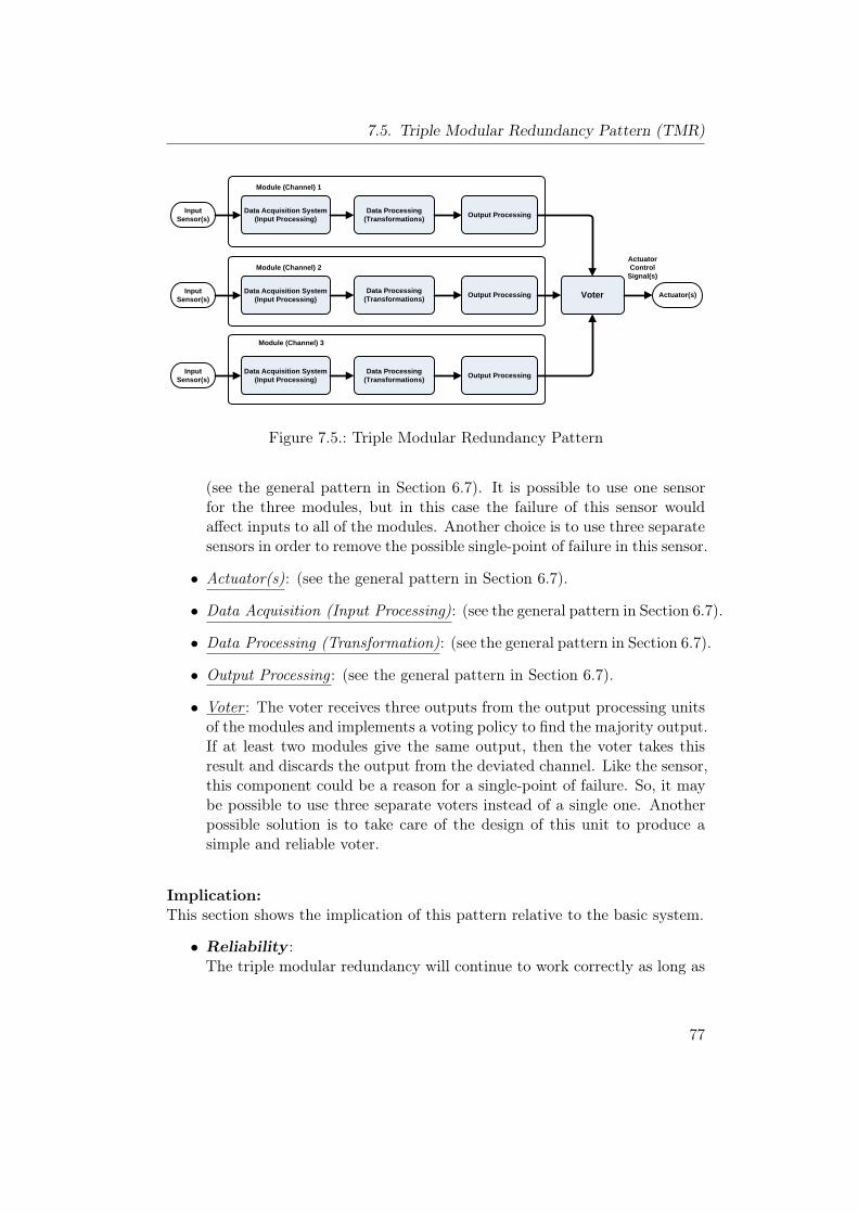
7.5. Triple Modular Redundancy Pattern (TMR)
Actuator(s)
Data Acquisition System (Input Processing)
Data Processing (Transformations) Output Processing Input
Sensor(s)
Data Acquisition System (Input Processing)
Data Processing (Transformations) Output Processing Input
Sensor(s)
Data Acquisition System (Input Processing)
Data Processing (Transformations) Output Processing Input
Sensor(s)
Voter
Module (Channel) 1
Module (Channel) 2
Module (Channel) 3
Actuator Control
Signal(s)
Figure 7.5.: Triple Modular Redundancy Pattern
(see the general pattern in Section 6.7). It is possible to use one sensorfor the three modules, but in this case the failure of this sensor wouldaffect inputs to all of the modules. Another choice is to use three separatesensors in order to remove the possible single-point of failure in this sensor.
• Actuator(s): (see the general pattern in Section 6.7).
• Data Acquisition (Input Processing): (see the general pattern in Section 6.7).
• Data Processing (Transformation): (see the general pattern in Section 6.7).
• Output Processing : (see the general pattern in Section 6.7).
• Voter : The voter receives three outputs from the output processing unitsof the modules and implements a voting policy to find the majority output.If at least two modules give the same output, then the voter takes thisresult and discards the output from the deviated channel. Like the sensor,this component could be a reason for a single-point of failure. So, it maybe possible to use three separate voters instead of a single one. Anotherpossible solution is to take care of the design of this unit to produce asimple and reliable voter.
Implication:This section shows the implication of this pattern relative to the basic system.
• Reliability :The triple modular redundancy will continue to work correctly as long as
77
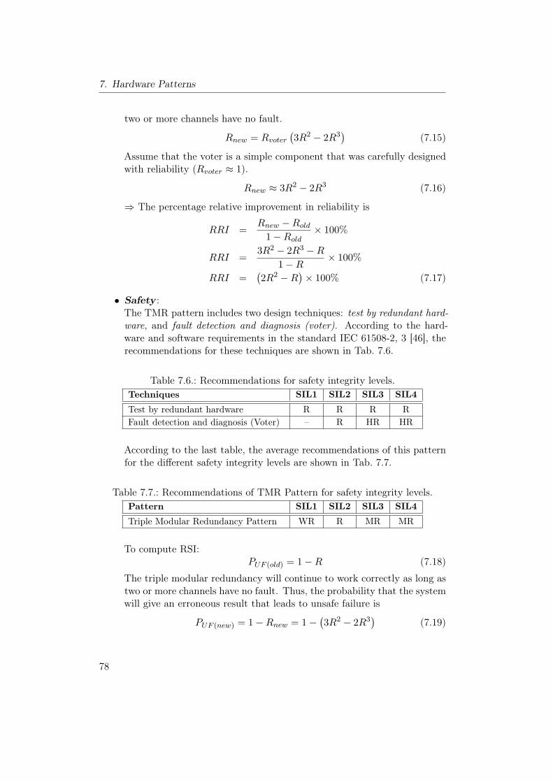
7. Hardware Patterns
two or more channels have no fault.
Rnew = Rvoter(3R2 − 2R3
)(7.15)
Assume that the voter is a simple component that was carefully designedwith reliability (Rvoter ≈ 1).
Rnew ≈ 3R2 − 2R3 (7.16)
⇒ The percentage relative improvement in reliability is
RRI =Rnew −Rold
1−Rold× 100%
RRI =3R2 − 2R3 −R
1−R× 100%
RRI =(2R2 −R
)× 100% (7.17)
• Safety :The TMR pattern includes two design techniques: test by redundant hard-ware, and fault detection and diagnosis (voter). According to the hard-ware and software requirements in the standard IEC 61508-2, 3 [46], therecommendations for these techniques are shown in Tab. 7.6.
Table 7.6.: Recommendations for safety integrity levels.Techniques SIL1 SIL2 SIL3 SIL4
Test by redundant hardware R R R RFault detection and diagnosis (Voter) – R HR HR
According to the last table, the average recommendations of this patternfor the different safety integrity levels are shown in Tab. 7.7.
Table 7.7.: Recommendations of TMR Pattern for safety integrity levels.Pattern SIL1 SIL2 SIL3 SIL4
Triple Modular Redundancy Pattern WR R MR MR
To compute RSI:PUF (old) = 1−R (7.18)
The triple modular redundancy will continue to work correctly as long astwo or more channels have no fault. Thus, the probability that the systemwill give an erroneous result that leads to unsafe failure is
PUF (new) = 1−Rnew = 1−(3R2 − 2R3
)(7.19)
78
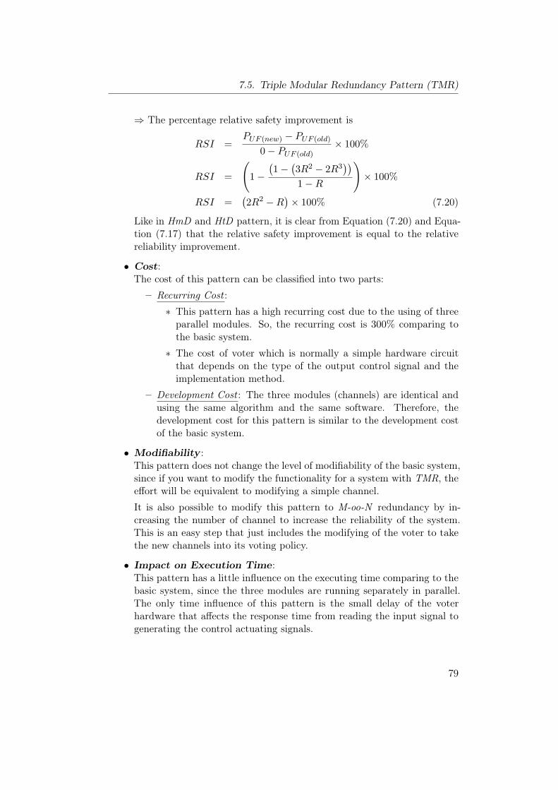
7.5. Triple Modular Redundancy Pattern (TMR)
⇒ The percentage relative safety improvement is
RSI =PUF (new) − PUF (old)
0− PUF (old)× 100%
RSI =
(1−
(1−
(3R2 − 2R3
))1−R
)× 100%
RSI =(2R2 −R
)× 100% (7.20)
Like in HmD and HtD pattern, it is clear from Equation (7.20) and Equa-tion (7.17) that the relative safety improvement is equal to the relativereliability improvement.
• Cost:The cost of this pattern can be classified into two parts:
– Recurring Cost :
∗ This pattern has a high recurring cost due to the using of threeparallel modules. So, the recurring cost is 300% comparing tothe basic system.
∗ The cost of voter which is normally a simple hardware circuitthat depends on the type of the output control signal and theimplementation method.
– Development Cost : The three modules (channels) are identical andusing the same algorithm and the same software. Therefore, thedevelopment cost for this pattern is similar to the development costof the basic system.
• Modifiability :This pattern does not change the level of modifiability of the basic system,since if you want to modify the functionality for a system with TMR, theeffort will be equivalent to modifying a simple channel.
It is also possible to modify this pattern to M-oo-N redundancy by in-creasing the number of channel to increase the reliability of the system.This is an easy step that just includes the modifying of the voter to takethe new channels into its voting policy.
• Impact on Execution Time:This pattern has a little influence on the executing time comparing to thebasic system, since the three modules are running separately in parallel.The only time influence of this pattern is the small delay of the voterhardware that affects the response time from reading the input signal togenerating the control actuating signals.
79
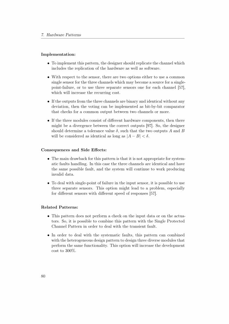
7. Hardware Patterns
Implementation:
• To implement this pattern, the designer should replicate the channel whichincludes the replication of the hardware as well as software.
• With respect to the sensor, there are two options either to use a commonsingle sensor for the three channels which may become a source for a single-point-failure, or to use three separate sensors one for each channel [57],which will increase the recurring cost.
• If the outputs from the three channels are binary and identical without anydeviation, then the voting can be implemented as bit-by-bit comparatorthat checks for a common output between two channels or more.
• If the three modules consist of different hardware components, then theremight be a divergence between the correct outputs [97]. So, the designershould determine a tolerance value δ, such that the two outputs A and Bwill be considered as identical as long as |A−B| < δ.
Consequences and Side Effects:
• The main drawback for this pattern is that it is not appropriate for system-atic faults handling. In this case the three channels are identical and havethe same possible fault, and the system will continue to work producinginvalid data.
• To deal with single-point of failure in the input sensor, it is possible to usethree separate sensors. This option might lead to a problem, especiallyfor different sensors with different speed of responses [57].
Related Patterns:
• This pattern does not perform a check on the input data or on the actua-tors. So, it is possible to combine this pattern with the Single ProtectedChannel Pattern in order to deal with the transient fault.
• In order to deal with the systematic faults, this pattern can combinedwith the heterogeneous design pattern to design three diverse modules thatperform the same functionality. This option will increase the developmentcost to 300%.
80
7.6. M-Out-Of-N Pattern (M-oo-N)
7.6. M-Out-Of-N Pattern (M-oo-N)
Other Names:M/N Parallel Redundancy Pattern.
Type:Hardware Pattern.
Abstract:The M-oo-N pattern includes homogeneous hot redundancy. It consists of Nidentical modules (channels) which operate in parallel to mask random faults,and to enhance system safety and reliability. The M-oo-N redundancy requiresthat at least M components succeed out of the total N parallel modules forthe system to succeed. An M-out-of-N voting algorithm is used in the votercomponent to allow system operating and providing the required functionalityin the presence of random faults without losing the input data.
Context:Developing an embedded system with/without fail-safe-state in a situation thatincludes high random failure rate and no limitation on redundancy, with thepurpose of improving system safety and reliability.
Problem:How to deal with random faults in order to increase the safety and reliabilityof the system without losing the input data.
Pattern Structure:The pattern structure, which is shown in Fig. 7.6, contains N identical modulesor channels in which M out of these N channels must be functioning for thesystem to be functioning and producing the correct actuation control signals.The voting element plays the main role in this pattern since it is used to findthe possible correct result by performing the M-oo-N voting strategy. Like inTMR, this pattern does not identify the type or the reason for the fault; it justdetermines the modules which contain the fault without searching for reasons.
The function of each unit is as follows:
• Module (Channel): (see the general pattern in Section 6.7).
• Input Sensor(s): It represents the source of information for this pattern(see the general pattern in Section 6.7). It is possible to use one sensorfor all the modules, but in this case the failure of this sensor would affect
81
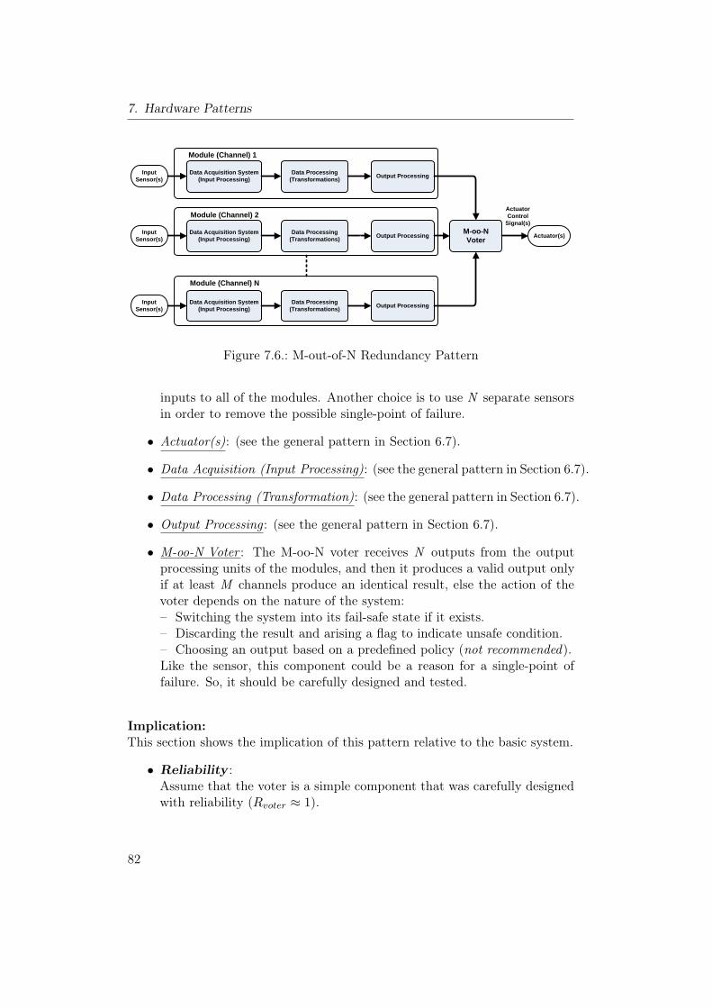
7. Hardware Patterns
Actuator(s)
Data Acquisition System (Input Processing)
Data Processing (Transformations) Output Processing Input
Sensor(s)
Data Acquisition System (Input Processing)
Data Processing (Transformations) Output Processing Input
Sensor(s)
Data Acquisition System (Input Processing)
Data Processing (Transformations) Output Processing Input
Sensor(s)
M-oo-NVoter
Module (Channel) 1
Module (Channel) 2
Module (Channel) N
Actuator Control
Signal(s)
Figure 7.6.: M-out-of-N Redundancy Pattern
inputs to all of the modules. Another choice is to use N separate sensorsin order to remove the possible single-point of failure.
• Actuator(s): (see the general pattern in Section 6.7).
• Data Acquisition (Input Processing): (see the general pattern in Section 6.7).
• Data Processing (Transformation): (see the general pattern in Section 6.7).
• Output Processing : (see the general pattern in Section 6.7).
• M-oo-N Voter : The M-oo-N voter receives N outputs from the outputprocessing units of the modules, and then it produces a valid output onlyif at least M channels produce an identical result, else the action of thevoter depends on the nature of the system:– Switching the system into its fail-safe state if it exists.– Discarding the result and arising a flag to indicate unsafe condition.– Choosing an output based on a predefined policy (not recommended).Like the sensor, this component could be a reason for a single-point offailure. So, it should be carefully designed and tested.
Implication:This section shows the implication of this pattern relative to the basic system.
• Reliability :Assume that the voter is a simple component that was carefully designedwith reliability (Rvoter ≈ 1).
82
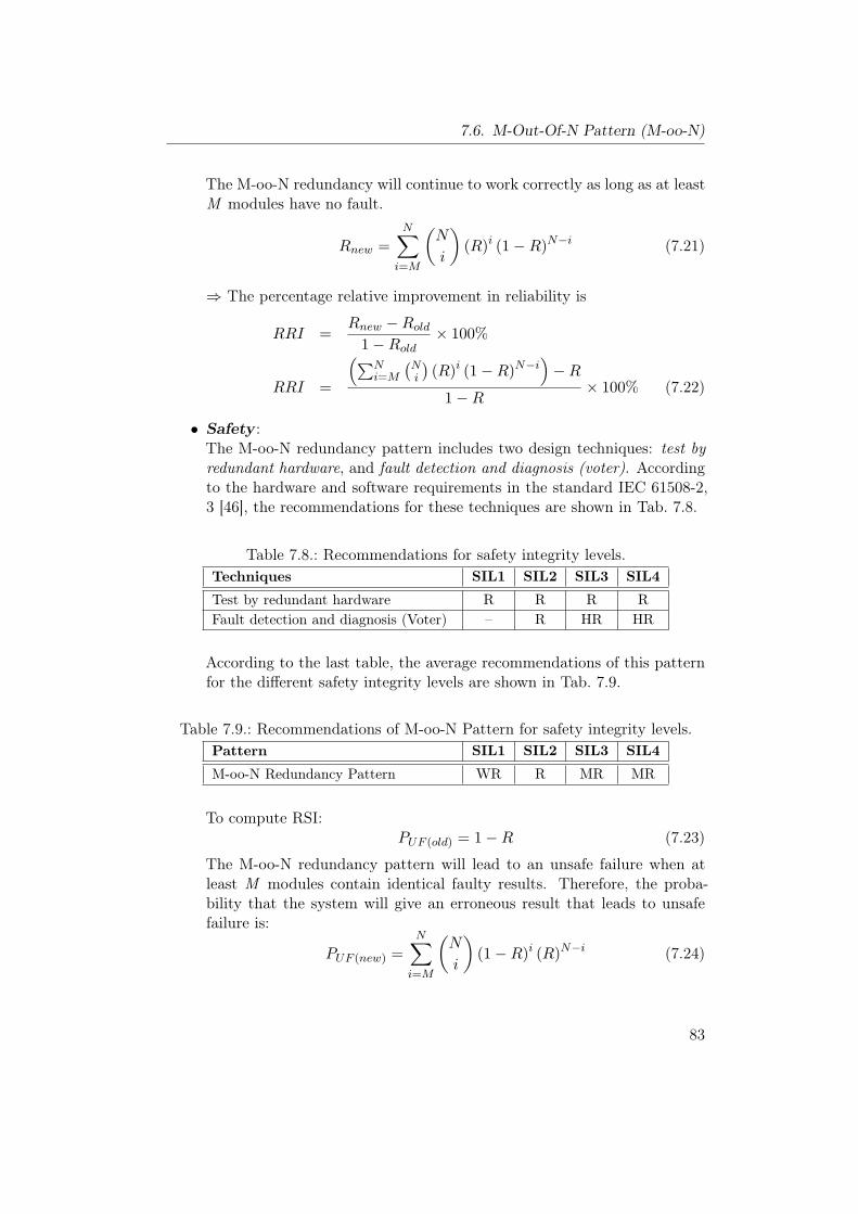
7.6. M-Out-Of-N Pattern (M-oo-N)
The M-oo-N redundancy will continue to work correctly as long as at leastM modules have no fault.
Rnew =N∑i=M
(N
i
)(R)i (1−R)N−i (7.21)
⇒ The percentage relative improvement in reliability is
RRI =Rnew −Rold
1−Rold× 100%
RRI =
(∑Ni=M
(Ni
)(R)i (1−R)N−i
)−R
1−R× 100% (7.22)
• Safety :The M-oo-N redundancy pattern includes two design techniques: test byredundant hardware, and fault detection and diagnosis (voter). Accordingto the hardware and software requirements in the standard IEC 61508-2,3 [46], the recommendations for these techniques are shown in Tab. 7.8.
Table 7.8.: Recommendations for safety integrity levels.Techniques SIL1 SIL2 SIL3 SIL4
Test by redundant hardware R R R RFault detection and diagnosis (Voter) – R HR HR
According to the last table, the average recommendations of this patternfor the different safety integrity levels are shown in Tab. 7.9.
Table 7.9.: Recommendations of M-oo-N Pattern for safety integrity levels.Pattern SIL1 SIL2 SIL3 SIL4
M-oo-N Redundancy Pattern WR R MR MR
To compute RSI:PUF (old) = 1−R (7.23)
The M-oo-N redundancy pattern will lead to an unsafe failure when atleast M modules contain identical faulty results. Therefore, the proba-bility that the system will give an erroneous result that leads to unsafefailure is:
PUF (new) =N∑i=M
(N
i
)(1−R)i (R)N−i (7.24)
83
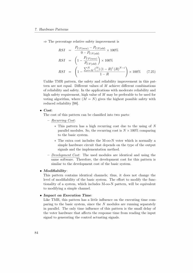
7. Hardware Patterns
⇒ The percentage relative safety improvement is
RSI =PUF (new) − PUF (old)
0− PUF (old)× 100%
RSI =(
1−PUF (new)
PUF (old)
)× 100%
RSI =
(1−
∑Ni=M
(Ni
)(1−R)i (R)N−i
1−R
)× 100% (7.25)
Unlike TMR pattern, the safety and reliability improvement in this pat-tern are not equal. Different values of M achieve different combinationsof reliability and safety. In the applications with moderate reliability andhigh safety requirement, high value of M may be preferable to be used forvoting algorithm, where (M = N) gives the highest possible safety withreduced reliability [98].
• Cost:The cost of this pattern can be classified into two parts:
– Recurring Cost :
∗ This pattern has a high recurring cost due to the using of Nparallel modules. So, the recurring cost is N × 100% comparingto the basic system.
∗ The extra cost includes the M-oo-N voter which is normally asimple hardware circuit that depends on the type of the outputsignals and the implementation method.
– Development Cost : The used modules are identical and using thesame software. Therefore, the development cost for this pattern issimilar to the development cost of the basic system.
• Modifiability :This pattern contains identical channels; thus, it does not change thelevel of modifiability of the basic system. The effort to modify the func-tionality of a system, which includes M-oo-N pattern, will be equivalentto modifying a simple channel.
• Impact on Execution Time:Like TMR, this pattern has a little influence on the executing time com-paring to the basic system, since the N modules are running separatelyin parallel. The only time influence of this pattern is the small delay ofthe voter hardware that affects the response time from reading the inputsignal to generating the control actuating signals.
84
7.6. M-Out-Of-N Pattern (M-oo-N)
Implementation:
• For homogeneous implementation of this pattern, the designer should usethe same hardware as well as the software for all the channels.
• To overcome the single-point of failure problem in the sensor, a separatesensor can be used for each channel, which will increase the recurring cost.
• If the outputs from the channels are binary and identical without anydeviation, then the voting can be implemented as bit-by-bit comparatorthat checks for a common output between at least M channels.
• If the hardware diversity concept is used in the implementation to solvethe problem of systematic faults, then the possible deviation in value ortime between the correct outputs should be taken into consideration inthe design of the voting system.
Consequences and Side Effects:
• The main drawback for this pattern is that it is not appropriate for sys-tematic faults handling because the channels are identical and have thesame possible fault. Thus, the M-oo-N pattern cannot detect this type offaults, which means that the system continues producing invalid data.
• If multiple sensors are used to deal with single-point of failure in the inputsensor, then this solution might lead to a problem, especially for differentsensors with different speed of responses [57].
Related Patterns:
• The M-oo-N redundancy pattern has a problem with systematic faults.So, it is possible to combine this pattern with the heterogeneous designpattern to design N heterogeneous modules with the same functionality.This option will increase the development cost by N times.
• Since the hardware channels run in parallel, the concept of software diver-sity can also be used to solve the problem of software faults.
• For the applications with high safety requirement, the M-oo-N pattern canbe used to implement the monitoring channel of the Monitor-ActuatorPattern. This combination will improve the safety monitoring of suchsystems by providing a high reliable monitoring channel.
85
7. Hardware Patterns
7.7. Monitor-Actuator Pattern (MA)
Other Names:–
Type:Hardware Pattern.
Abstract:The Monitor-Actuator Pattern [37] is a special type of heterogeneous redun-dancy that is suitable for safety critical systems with low availability require-ments and a fail-safe state, which is a condition of the system known to bealways safe [37]. The MA pattern consists of two different channels (modules):A primary channel called the actuation channel, which performs the main actionsuch as controlling some actuators, and a monitoring channel, which providesa monitoring for the actuation channel in order to detect and to identify thepossible faults and then to make the actuation channel entering its fail-safestate. The monitoring channel differs from the actuator channel such that if itcontains any fault, the actuation channel continues to operate properly.
Context:Developing an embedded system with a given fail-safe state and low availabilityrequirements, where some level of redundancy is acceptable.
Problem:How to improve the safety of an embedded system in the presence of a single-point of failure in a system that includes a fail-safe state and low availabilityrequirements at reasonable cost.
Pattern Structure:The structure of the Monitor-Actuator Pattern is shown in Fig. 7.7. It consistsof two channels that run independently and in parallel to provide the requiredfunctionality and a monitoring method to switch the system into its fail-safestate in the presence of failure.
The function of each unit is as follows:
• Actuation Channel : (see the general pattern in Section 6.7).
• Input Data Source: (see the general pattern in Section 6.7).
• Actuator(s): (see the general pattern in Section 6.7).
86
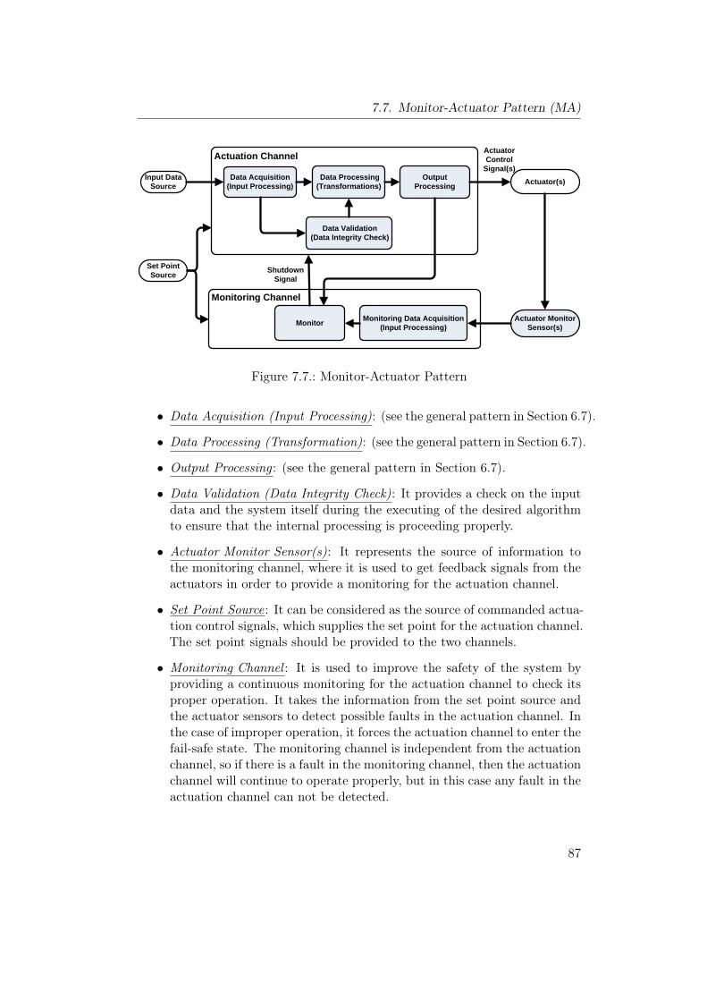
7.7. Monitor-Actuator Pattern (MA)
Actuator(s)Data Acquisition(Input Processing)
Data Processing (Transformations)
Output Processing
Input Data Source
Data Validation (Data Integrity Check)
Monitoring Data Acquisition(Input Processing)
Actuator Monitor Sensor(s)Monitor
Set Point Source
Monitoring Channel
Shutdown Signal
Actuation Channel ActuatorControl
Signal(s)
Figure 7.7.: Monitor-Actuator Pattern
• Data Acquisition (Input Processing): (see the general pattern in Section 6.7).
• Data Processing (Transformation): (see the general pattern in Section 6.7).
• Output Processing : (see the general pattern in Section 6.7).
• Data Validation (Data Integrity Check): It provides a check on the inputdata and the system itself during the executing of the desired algorithmto ensure that the internal processing is proceeding properly.
• Actuator Monitor Sensor(s): It represents the source of information tothe monitoring channel, where it is used to get feedback signals from theactuators in order to provide a monitoring for the actuation channel.
• Set Point Source: It can be considered as the source of commanded actua-tion control signals, which supplies the set point for the actuation channel.The set point signals should be provided to the two channels.
• Monitoring Channel : It is used to improve the safety of the system byproviding a continuous monitoring for the actuation channel to check itsproper operation. It takes the information from the set point source andthe actuator sensors to detect possible faults in the actuation channel. Inthe case of improper operation, it forces the actuation channel to enter thefail-safe state. The monitoring channel is independent from the actuationchannel, so if there is a fault in the monitoring channel, then the actuationchannel will continue to operate properly, but in this case any fault in theactuation channel can not be detected.
87
7. Hardware Patterns
• Monitoring Data Acquisition: It collects the raw data from the actuatorsensors and may convert the data to another form as in analog to digitalconverter (ADC). Finally, it transfers the data to the monitor component.
• Monitor : The monitor takes the information about the outputs of theactuators, which is collected by the actuator sensors and processed bythe monitoring acquisition system, and compares it with the provided setpoints to make sure that the actuation channel is working properly. Ifthe result of the comparison shows improper operation in the actuationchannel, the monitor generates a shutdown signal to the actuation channel.
Implication:This section shows the implication of this pattern relative to the basic system.
• Reliability :As shown previously, this pattern is used to detect and to identify thefaults in the actuation channel, then to generate the shutdown signal toforce the actuation channel entering its fail-safe state. On the other hand,this pattern does not change the failure rate of the system (λnew = λold),and the actuation channel cannot continue to function when a fault isdetected. Thus, this pattern does not improve the reliability of the system.
Rnew = Rold (7.26)
⇒ The percentage relative improvement in reliability is
RRI =Rnew −Rold
1−Rold× 100% = 0% (7.27)
• Safety :The Monitor-Actuator Pattern includes two design techniques: test by re-dundant hardware and safety bag techniques. According to the hardwareand software requirements in the standard IEC 61508-2, 3 [46], the recom-mendations for these techniques are shown in Tab. 7.10.
Table 7.10.: Recommendations for safety integrity levels.Techniques SIL1 SIL2 SIL3 SIL4
Test by redundant hardware R R R RSafety bag techniques – R R R
According to the last table, the average recommendations of this patternfor the different safety integrity levels are shown in Tab. 7.11.
88
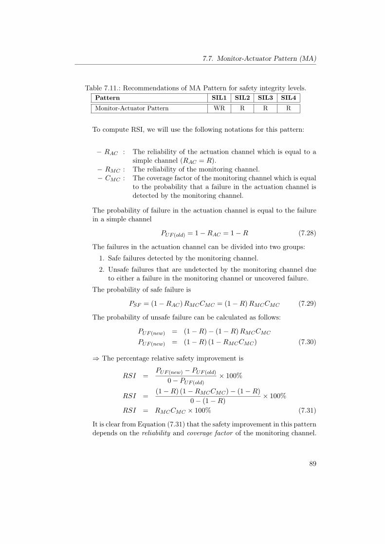
7.7. Monitor-Actuator Pattern (MA)
Table 7.11.: Recommendations of MA Pattern for safety integrity levels.Pattern SIL1 SIL2 SIL3 SIL4
Monitor-Actuator Pattern WR R R R
To compute RSI, we will use the following notations for this pattern:
− RAC : The reliability of the actuation channel which is equal to asimple channel (RAC = R).
− RMC : The reliability of the monitoring channel.− CMC : The coverage factor of the monitoring channel which is equal
to the probability that a failure in the actuation channel isdetected by the monitoring channel.
The probability of failure in the actuation channel is equal to the failurein a simple channel
PUF (old) = 1−RAC = 1−R (7.28)
The failures in the actuation channel can be divided into two groups:
1. Safe failures detected by the monitoring channel.
2. Unsafe failures that are undetected by the monitoring channel dueto either a failure in the monitoring channel or uncovered failure.
The probability of safe failure is
PSF = (1−RAC)RMCCMC = (1−R)RMCCMC (7.29)
The probability of unsafe failure can be calculated as follows:
PUF (new) = (1−R)− (1−R)RMCCMC
PUF (new) = (1−R) (1−RMCCMC) (7.30)
⇒ The percentage relative safety improvement is
RSI =PUF (new) − PUF (old)
0− PUF (old)× 100%
RSI =(1−R) (1−RMCCMC)− (1−R)
0− (1−R)× 100%
RSI = RMCCMC × 100% (7.31)
It is clear from Equation (7.31) that the safety improvement in this patterndepends on the reliability and coverage factor of the monitoring channel.
89
7. Hardware Patterns
• Cost:The cost of this pattern can be classified into two parts:
– Recurring Cost : The extra cost includes
∗ The cost of extra sensors (actuator sensors).
∗ The cost of the monitoring channel which contains two compo-nents: the data acquisition and the monitor. Comparing to thebasic channel, this new channel is simple and less expensive.
– Development Cost : It includes the cost for developing the monitoringchannel.
In general, this pattern is less expensive comparing to the other patternsthat include high level of redundancy.
• Modifiability :It is not difficult to modify this pattern by adding extra functionality tothe actuation channel. This step involves the need to modify the monitor-ing channel to provide a monitoring to the new features, which will includeadditional sensors and the modification of the monitoring data acquisitionand the Monitor component to take the new features into consideration.
• Impact on Execution Time:The two channels in this pattern run simultaneously in parallel; thus thereis no effect for the monitoring channel on the actuation during the normaloperation of the system. Even if there is a fault in the monitoring channel,the actuation channel will not be affected. Therefore, there is no influenceon the execution time of the actuation channel.
Implementation:
• In the implementation of the monitoring channel, many factors shouldbe taken into consideration such as the time lag, measurement accuracy,computational accuracies, data formatting errors, and many other factorsthat might affect the comparison process.
• It is necessary to distinguish between transient and persistent faults, be-cause in some situation a single transient fault may not be harmful andcan be neglected, but this is not the case for persistent fault that shouldbe detected by the monitoring channel. So, it is a good idea for the mon-itoring channel to store some historical information about the monitoredvalue which could be helpful to determine whether the detected valuerepresents a transient or persistent fault.
90
7.7. Monitor-Actuator Pattern (MA)
• As shown previously, if there is any fault in the monitoring channel, thenthe system can operate properly, but there will be a problem if a sec-ond fault occurs in the actuation channel. Thus, the monitoring channelmust be checked to make sure that the system meets the required safetyfunction. The check can be one or a combination of the following :
1. Power-On Self Tests (POSTs).
2. Periodic Built-In Tests (BITs).
3. A life tick message exchanges between the actuator and monitoringchannel.
If the used check fails, then this indicates that a fault exists in the system,and the fail-safe state is entered.
• The previous checks must be preformed in a time interval less than themean-time between failures (MTBF ) of the monitoring channel and anyof its components [37].
Consequences and Side Effects:The main drawback for this pattern is that it is not appropriate for applicationswith high availability requirements.
Related Patterns:The safety of the actuation channel depends on the reliability of the monitoringchannel that generates the shutdown signal in the presence of a fault in theactuation channel. So, it is possible to use more complex patterns for themonitoring channel such as homogeneous duplex, heterogeneous duplex, triplemodular redundancy, and M-oo-N redundancy pattern.
91
7. Hardware Patterns
7.8. Sanity Check Pattern (SC)
Other Names:–
Type:Hardware Pattern.
Abstract:The Sanity Check Pattern [37] is considered as a lightweight pattern which isused to ensure that the basic channel is approximately correct. It is a variant ofthe Monitor-Actuator Pattern which is suitable for a situation that has low avail-ability requirements, a fail-safe state, and when the fine control of the systemdoes not affect the system safety [37]. Similar to the Monitor-Actuator Pattern,it consists of two different channels (modules): An actuation channel, whichperforms the action such as controlling some actuators, and a sanity channel,which provides a monitoring to the actuation channel to ensure that the actua-tion output is approximately correct and within some fixed range. The sanitychannel is different from the actuation channel and it may include lower costand lower accuracy sensors used to identify faults that include a large deviationin the actuator output from the commanded set point.
Context:Developing an embedded system with a fail-safe state and low availability re-quirements where fine control is not a safety property of the actuation channel.
Problem:How to improve the safety of an embedded system in the presence of single-point of failure in a system that includes a fail-safe state and low availabilityrequirement. This involves how to continue providing the required safety levelto ensure that the system does no injure or harm when there is any deviationin the output of the actuators from the commanded set point at a low andreasonable cost.
Pattern Structure:The Sanity Check Pattern is derived from the Monitor-Actuator Pattern sincethey have identical structures. The pattern structure is shown in Fig. 7.8. Itconsists of two channels that run independently and in parallel to provide therequired functionality, and a safety monitoring method to switch the systeminto its fail-safe state in the presence of failure.
92
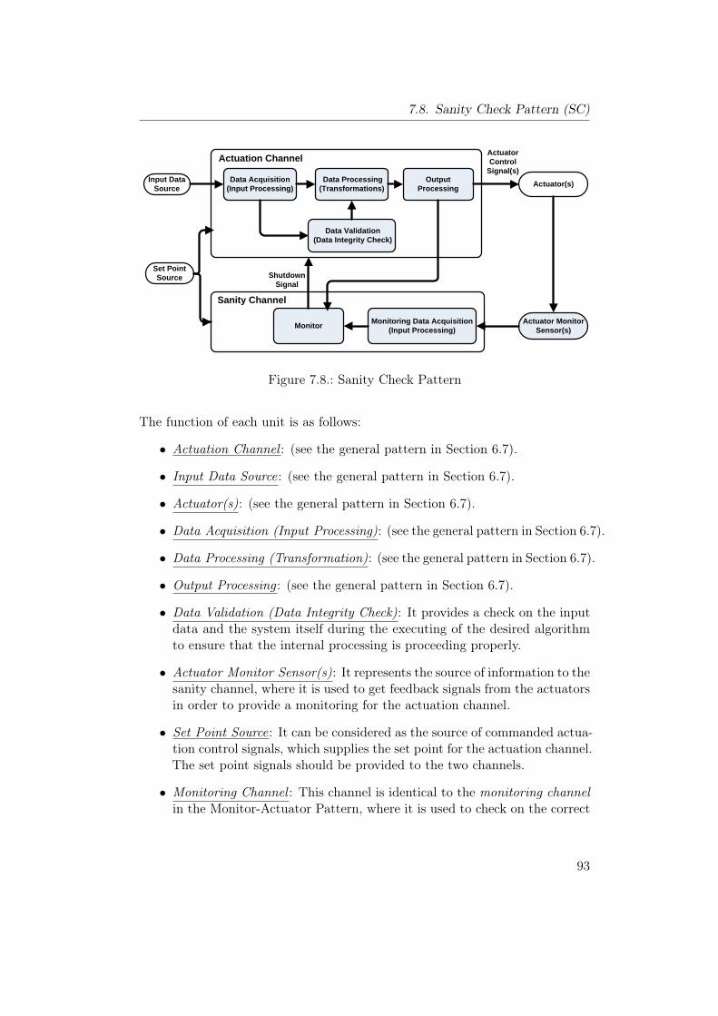
7.8. Sanity Check Pattern (SC)
Actuator(s)Data Acquisition(Input Processing)
Data Processing (Transformations)
Output Processing
Input Data Source
Data Validation (Data Integrity Check)
Monitoring Data Acquisition(Input Processing)
Actuator Monitor Sensor(s)Monitor
Set Point Source
Sanity Channel
Shutdown Signal
Actuation Channel ActuatorControl
Signal(s)
Figure 7.8.: Sanity Check Pattern
The function of each unit is as follows:
• Actuation Channel : (see the general pattern in Section 6.7).
• Input Data Source: (see the general pattern in Section 6.7).
• Actuator(s): (see the general pattern in Section 6.7).
• Data Acquisition (Input Processing): (see the general pattern in Section 6.7).
• Data Processing (Transformation): (see the general pattern in Section 6.7).
• Output Processing : (see the general pattern in Section 6.7).
• Data Validation (Data Integrity Check): It provides a check on the inputdata and the system itself during the executing of the desired algorithmto ensure that the internal processing is proceeding properly.
• Actuator Monitor Sensor(s): It represents the source of information to thesanity channel, where it is used to get feedback signals from the actuatorsin order to provide a monitoring for the actuation channel.
• Set Point Source: It can be considered as the source of commanded actua-tion control signals, which supplies the set point for the actuation channel.The set point signals should be provided to the two channels.
• Monitoring Channel : This channel is identical to the monitoring channelin the Monitor-Actuator Pattern, where it is used to check on the correct
93
7. Hardware Patterns
operation of the actuation channel. It takes information from the set pointsource and the actuator sensors to detect possible faults in the actuationchannel. In the case of great difference between the set point and themeasured value, the sanity channel forces the actuation channel enteringthe fail-safe state. The sanity channel is independent from the actuationchannel, so if there is a fault in the sanity channel, the actuation channelcontinues to operate properly, but in this case any further fault in theactuation channel cannot be detected.
• Monitoring Data Acquisition: It collects the raw data from the actuatorsensors and may convert the data to another form as in analog to digitalconverter (ADC). Finally, it transfers the data to the monitor component.
• Monitor : The monitor takes the information about the outputs of theactuators, which is collected by the actuator sensors and processed by themonitoring acquisition system, and compares it roughly with the providedset point commands to ensure that the actuation output is approximatelycorrect and within a given range. If the result of the comparison showsthat the output is totally incorrect and may affect the safety of the system,the monitor generates a shutdown signal to the actuation channel. Thecomparison process in this unit is very simple and less accurate than inthe Monitor-Actuator Pattern. So, this component is simpler and lessexpensive than the monitor unit in the Monitor-Actuator Pattern.
Implication:This section shows the implication of this pattern relative to the basic system.
• Reliability :Like in MA pattern, this pattern is used to detect and to identify the faultsin the actuation channel, then to generate the shutdown signal to forcethe actuation channel entering its fail-safe state. On the other hand, thispattern does not change the failure rate of the system (λnew = λold), andthe actuation channel cannot continue to function when a fault is detected.Thus, this pattern does not improve the reliability of the system.
Rnew = Rold (7.32)
⇒ The percentage relative improvement in reliability is
RRI =Rnew −Rold
1−Rold× 100% = 0% (7.33)
94
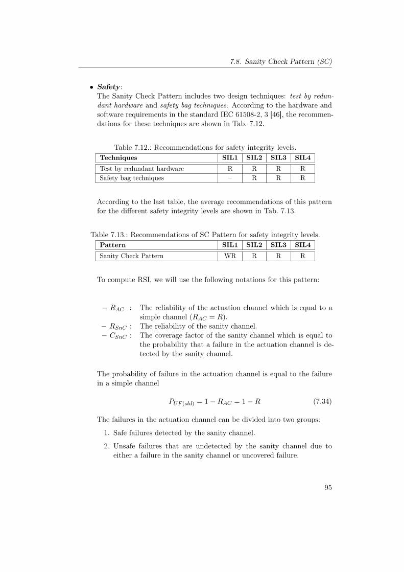
7.8. Sanity Check Pattern (SC)
• Safety :The Sanity Check Pattern includes two design techniques: test by redun-dant hardware and safety bag techniques. According to the hardware andsoftware requirements in the standard IEC 61508-2, 3 [46], the recommen-dations for these techniques are shown in Tab. 7.12.
Table 7.12.: Recommendations for safety integrity levels.Techniques SIL1 SIL2 SIL3 SIL4
Test by redundant hardware R R R RSafety bag techniques – R R R
According to the last table, the average recommendations of this patternfor the different safety integrity levels are shown in Tab. 7.13.
Table 7.13.: Recommendations of SC Pattern for safety integrity levels.Pattern SIL1 SIL2 SIL3 SIL4
Sanity Check Pattern WR R R R
To compute RSI, we will use the following notations for this pattern:
− RAC : The reliability of the actuation channel which is equal to asimple channel (RAC = R).
− RSnC : The reliability of the sanity channel.− CSnC : The coverage factor of the sanity channel which is equal to
the probability that a failure in the actuation channel is de-tected by the sanity channel.
The probability of failure in the actuation channel is equal to the failurein a simple channel
PUF (old) = 1−RAC = 1−R (7.34)
The failures in the actuation channel can be divided into two groups:
1. Safe failures detected by the sanity channel.
2. Unsafe failures that are undetected by the sanity channel due toeither a failure in the sanity channel or uncovered failure.
95
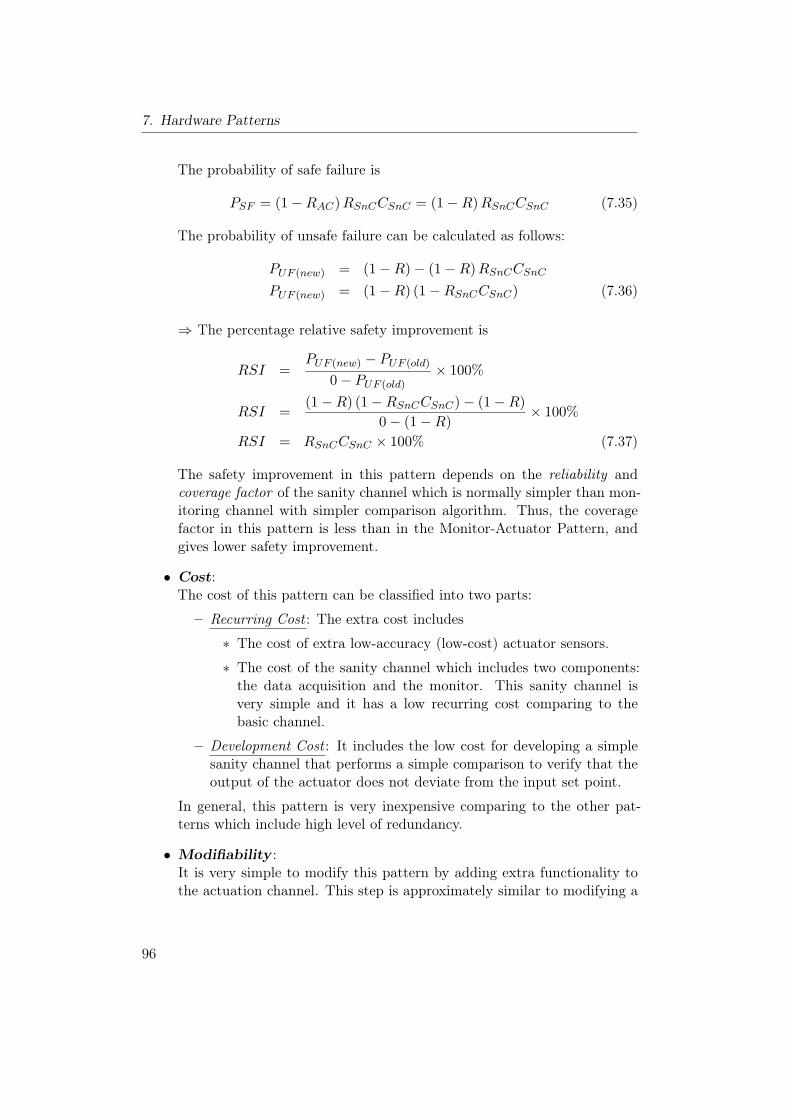
7. Hardware Patterns
The probability of safe failure is
PSF = (1−RAC)RSnCCSnC = (1−R)RSnCCSnC (7.35)
The probability of unsafe failure can be calculated as follows:
PUF (new) = (1−R)− (1−R)RSnCCSnCPUF (new) = (1−R) (1−RSnCCSnC) (7.36)
⇒ The percentage relative safety improvement is
RSI =PUF (new) − PUF (old)
0− PUF (old)× 100%
RSI =(1−R) (1−RSnCCSnC)− (1−R)
0− (1−R)× 100%
RSI = RSnCCSnC × 100% (7.37)
The safety improvement in this pattern depends on the reliability andcoverage factor of the sanity channel which is normally simpler than mon-itoring channel with simpler comparison algorithm. Thus, the coveragefactor in this pattern is less than in the Monitor-Actuator Pattern, andgives lower safety improvement.
• Cost:The cost of this pattern can be classified into two parts:
– Recurring Cost : The extra cost includes
∗ The cost of extra low-accuracy (low-cost) actuator sensors.
∗ The cost of the sanity channel which includes two components:the data acquisition and the monitor. This sanity channel isvery simple and it has a low recurring cost comparing to thebasic channel.
– Development Cost : It includes the low cost for developing a simplesanity channel that performs a simple comparison to verify that theoutput of the actuator does not deviate from the input set point.
In general, this pattern is very inexpensive comparing to the other pat-terns which include high level of redundancy.
• Modifiability :It is very simple to modify this pattern by adding extra functionality tothe actuation channel. This step is approximately similar to modifying a
96
7.8. Sanity Check Pattern (SC)
basic channel with relatively little extra work. This extra work involvesthe need to add more actuator sensors and to modify the comparisonprocess of the monitor to cover the new features.
• Impact on Execution Time:The two channels run simultaneously in parallel and there is no effect forthe sanity channel on the actuation channel during the normal operationof the system. Even if there is fault in the sanity channel, the actuationchannel will not be affected. Therefore, there is no influence on the timeof execution for the actuation channel.
Implementation:
• To implement this pattern, two different types of sensors will be used:high sensitivity sensors for the actuation channel, and low-cost and low-sensitivity sensors for the sanity channel.
• The implementation of the monitor component is very simple since it is avery simple unit that includes a simple algorithm to perform the requiredbroad range comparison.
• Unlike the original Monitor-Actuator Pattern, it is not necessary to takeinto consideration the time lag, measurement accuracy, computational ac-curacies, and data formatting errors in the implementation of this patternbecause this pattern just includes a simple approximate comparison.
Consequences and Side Effects:The main drawback for this pattern is that it has low coverage, which makes itnot suitable for applications with high availability requirements.
Related Patterns:It is possible to use the Monitor-Actuator Pattern for more accurate check onthe actuator channel, but this will increase the design and recurring cost. Inthe case where no fail-safe state exists, more complex pattern may be used suchas homogeneous and heterogeneous duplex pattern.
97
7. Hardware Patterns
7.9. Watchdog Pattern (WD)
Other Names:Watchdog Timer, Watchdog Processor, Hardware Watchdog Pattern [78].
Type:Hardware Pattern.
Abstract:The Watchdog Pattern [37] is a very lightweight and inexpensive pattern withminimal coverage that is used to check the internal computational execution ofthe actuation channel. It is widely used in the embedded systems to make surethat the time-dependent computational processing is proceeding properly as ex-pected in a predefined order [37]. This pattern includes a component called awatchdog that receives periodic messages from the watched channel. If an eventoccurs too late or out of order, then the watchdog issues a shutdown signal or acorrective action in order to avoid losing control of the system. The watchdogpattern is rarely used alone in safety-critical systems, and it is normally usedwith other patterns to improve the system safety.
Context:Developing a real time embedded system with a given fail-safe state or a correc-tive action and low availability requirements.
Problem:This pattern is used to solve the following problems:
• How to add additional safety to the system by providing a simple andlow-cost way to watch, detect and handle faults during the execution.
• How to make sure that the internal computational processing of the actu-ation channel is proceeding properly as expected.
• How to identify time-based faults.• How to improve deadlock detection using “Keyed Watchdog”.
Pattern Structure:The Watchdog Pattern is a very simple variant of the Sanity Check Pattern.While it has an actuation channel to do end-to-end actuation, it differs in thesanity channel which is replaced in this pattern with the watchdog component.The watchdog receives liveness messages (Strokes) from the actuation channelon a periodic or in a predefined-sequence base. The watchdog must be strokedwithin a specified period of time or it will initiate a corrective action such as a
98
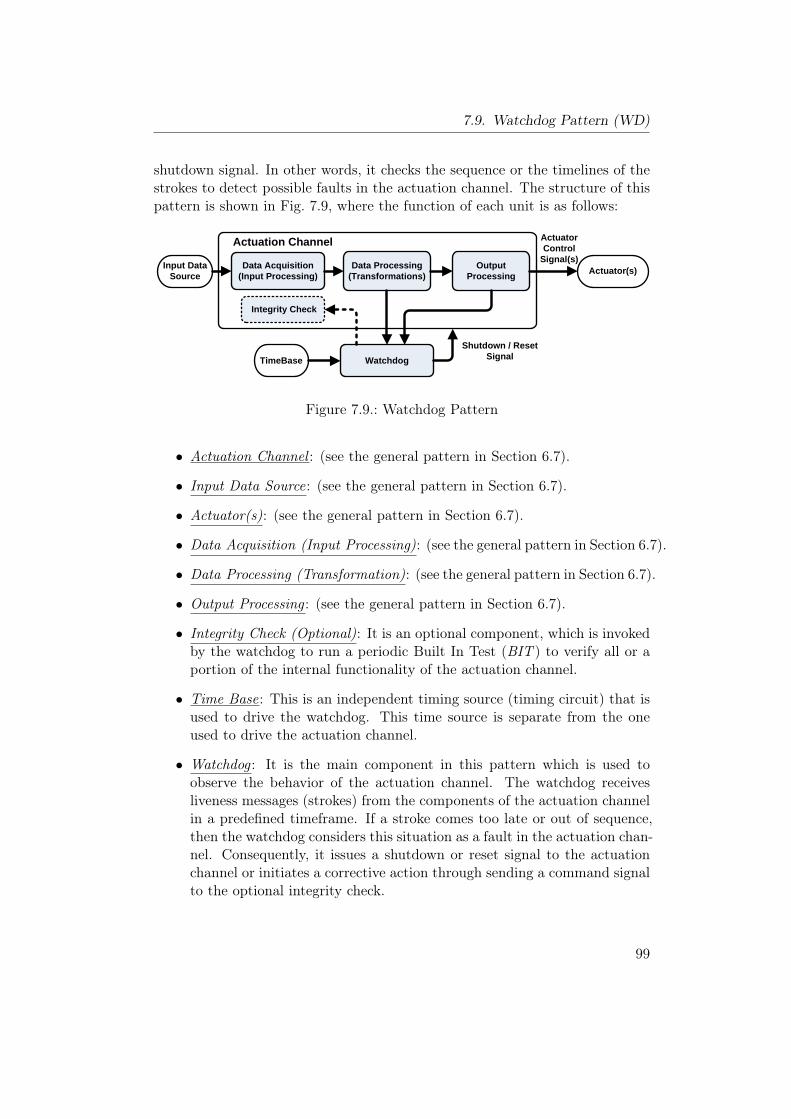
7.9. Watchdog Pattern (WD)
shutdown signal. In other words, it checks the sequence or the timelines of thestrokes to detect possible faults in the actuation channel. The structure of thispattern is shown in Fig. 7.9, where the function of each unit is as follows:
Actuator(s)Data Acquisition(Input Processing)
Data Processing (Transformations)
Output Processing
Input Data Source
Integrity Check
WatchdogTimeBase
Actuation Channel
Shutdown / ResetSignal
ActuatorControl
Signal(s)
Figure 7.9.: Watchdog Pattern
• Actuation Channel : (see the general pattern in Section 6.7).
• Input Data Source: (see the general pattern in Section 6.7).
• Actuator(s): (see the general pattern in Section 6.7).
• Data Acquisition (Input Processing): (see the general pattern in Section 6.7).
• Data Processing (Transformation): (see the general pattern in Section 6.7).
• Output Processing : (see the general pattern in Section 6.7).
• Integrity Check (Optional): It is an optional component, which is invokedby the watchdog to run a periodic Built In Test (BIT ) to verify all or aportion of the internal functionality of the actuation channel.
• Time Base: This is an independent timing source (timing circuit) that isused to drive the watchdog. This time source is separate from the oneused to drive the actuation channel.
• Watchdog : It is the main component in this pattern which is used toobserve the behavior of the actuation channel. The watchdog receivesliveness messages (strokes) from the components of the actuation channelin a predefined timeframe. If a stroke comes too late or out of sequence,then the watchdog considers this situation as a fault in the actuation chan-nel. Consequently, it issues a shutdown or reset signal to the actuationchannel or initiates a corrective action through sending a command signalto the optional integrity check.
99
7. Hardware Patterns
Implication:This section shows the implication of this pattern relative to the basic system.
• Reliability :The reliability improvement of the watchdog pattern is very small and de-pends on the response-action to the timeout event. If there is a correctiveaction, then the reliability improvement depends on the coverage of thecorrective action. But if the watchdog just initiates a shutdown signalto force the actuation channel entering its fail-safe state, then this pat-tern will not change the failure rate of the system (λnew = λold), and theactuation channel cannot continue to function when a fault is detected.Therefore, this pattern does not improve the reliability of the system.
Rnew = Rold (7.38)
⇒ The percentage relative improvement in reliability is
RRI =Rnew −Rold
1−Rold× 100% = 0% (7.39)
• Safety :The watchdog pattern includes a single design technique, which is pro-gram sequence monitoring. According to the hardware requirements inthe standard IEC 61508-2 [46], the recommendations for this techniqueare shown in Tab. 7.14.
Table 7.14.: Recommendations of WD Pattern for safety integrity levels.Techniques SIL1 SIL2 SIL3 SIL4
Program sequence monitoring HR HR HR HR
To compute RSI, we will use the following notations for this pattern:
− RAC : The reliability of the actuation channel which is equal to asimple channel (RAC = R).
− RWD : The reliability of the watchdog component.− CWD : The coverage factor of the watchdog component which is
equal to the probability that a failure in the actuation chan-nel is detected by the sanity watchdog.
The probability of failure in the actuation channel is equal to the failurein a simple channel
PUF (old) = 1−RAC = 1−R (7.40)
100
7.9. Watchdog Pattern (WD)
The failures in the actuation channel can be divided into two groups:
1. Safe failures detected by the watchdog.
2. Unsafe failures that are undetected by the watchdog due to either afailure in the watchdog or the minimal coverage of the watchdog.
The probability of safe failure is
PSF = (1−RAC)RWDCWD = (1−R)RWDCWD (7.41)
The probability of unsafe failure can be calculated as follows:
PUF (new) = (1−R)− (1−R)RWDCWD
PUF (new) = (1−R) (1−RWDCWD) (7.42)
⇒ The percentage relative safety improvement is
RSI =PUF (new) − PUF (old)
0− PUF (old)× 100%
RSI =(1−R) (1−RWDCWD)− (1−R)
0− (1−R)× 100%
RSI = RWDCWD × 100% (7.43)
If we assume that the watchdog was carefully designed (RWD ≈ 1) then
RSI ≈ CWD × 100% (7.44)
Equation (7.44) shows that the safety improvement in this pattern de-pends on the coverage of the watchdog which normally includes the mini-mal coverage. For this reason, the safety improvement is less than in theSanity Check Pattern.
• Cost:The cost of this pattern can be classified into two parts:
– Recurring Cost : The extra cost includes the cost of the watchdog,which is a simple component, and the independent timing source.
– Development Cost : This pattern has the lowest development costwhich depends on the recovery action initiated by the watchdog.
In general, this pattern is inexpensive with low cost comparing to theother patterns that include high level of redundancy.
• Modifiability :It is very simple to modify this pattern by adding extra functionality.Theonly things that should be done, is to know whether the new componentsneed to send stroke messages to the watchdog or not.
101
7. Hardware Patterns
• Impact on Execution Time:Since the actuation channel and the watchdog run simultaneously in par-allel, there is no effect for the watchdog on the actuation channel duringthe normal operation of the system except the execution of the built intests that may be initiated by the watchdog when it is stroked.
Implementation:
• The watchdog component is simple and often implemented as a separatehardware to protect the system from software faults.
• To provide protection from time-based faults, a separate timing sourcesuch as crystal or an R-C circuit must be used.
• There is a problem for the watchdog that is called Live-Lock problemwhich occurs when the actuation channel gets stuck in loop that strokesthe watchdog without performing the appropriate actuation. To avoidthis problem, the watchdog may require a specific data in a predefined-sequence to occur with the strokes which is called Keyed Watchdog.
• The best approach to implement a Keyed Watchdog is to have the keysdynamically generated instead of storing them in a memory [37].
• To increase the fault coverage, it is common to invoke a BIT, CRC, orstack overflow check when the watchdog is stroked to ensure that thecomputational processing of the actuation channel is proceeding properly.
Consequences and Side Effects:The main drawback for this pattern is the minimal coverage of the watchdog;thus, it is rarely used alone in safety critical systems. It may be combined withother safety patterns.
Related Patterns:The Watchdog Pattern is a very lightweight pattern that is rarely used alone insafety critical system. It is normally associated with other patterns as a methodto identify time-based faults and to drive periodic BITs. In the case where nofail-safe state exists, more complex pattern may be used such as homogeneousand heterogeneous duplex pattern.
102
7.10. Safety Executive Pattern (SE)
7.10. Safety Executive Pattern (SE)
Other Names:Safety Kernel Pattern [36].
Type:Hardware Pattern.
Abstract:The Safety Executive Pattern [37] is a large scale pattern that is suitable for com-plex and highly safety-critical systems. It is a smart extension of the WatchdogPattern targeting the problem where a shutdown of the system by the actua-tion channel itself might be critical or take too long time. This problem occursespecially in those systems in which a complicated series of steps involving sev-eral components is necessary to reach a fail-safe state. Therefore, the SafetyExecutive Pattern uses a watchdog in a combination with an additional safetyexecutive component, which is responsible for the shutdown of the system assoon as the watchdog sends a shutdown signal. If the system has a fail-safestate, the safety executive component controls the shutdown of the actuationchannels. Otherwise, the safety executive component has to conduct actionsrequired to delegate an additional fail-safe processing channel.
Context:Developing a highly safety-critical system in a situation where:
− The actuation channel requires a risk reduction by safety measures.− The considered system has at least one fail-safe state, or an additional
fail-safe processing channel has to be used to overtake necessary actions.− The shutdown of the actuation channel is a complex process, where several
safety-related actions have to be controlled simultaneously.− A sufficient determination of failures in the actuation channel can be
achieved by a watchdog.
Problem:How to provide a centralized and consistent method for monitoring and control-ling the execution of a complex safety measure in case of failures.
Pattern Structure:The Safety Executive Pattern is based on an actuation channel to perform therequired functionality and an optional fail-safe processing channel that is dedi-cated to the execution and control of the fail-safe processing. The central part
103
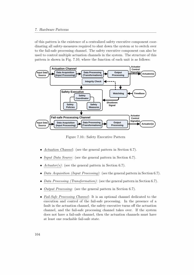
7. Hardware Patterns
of this pattern is the existence of a centralized safety executive component coor-dinating all safety-measures required to shut down the system or to switch overto the fail-safe processing channel. The safety executive component can also beused to control multiple actuation channels in the system. The structure of thispattern is shown in Fig. 7.10, where the function of each unit is as follows:
Actuator(s)Data Acquisition(Input Processing)
Data Processing (Transformations)
Output Processing
Input Data Source
Integrity Check
Watchdog TimeBase
Actuator(s)Data Acquisition(Input Processing)
Data Processing (Transformations)
Output Processing
Input Data Source
Safety Coordinator
Safety Measures
Safety Policies
Actuation ChannelActuatorControl
Signal(s)
Safety Executive
ShutdownSignal
ActuatorControl
Signal(s)Fail-safe Processing Channel
Figure 7.10.: Safety Executive Pattern
• Actuation Channel : (see the general pattern in Section 6.7).
• Input Data Source: (see the general pattern in Section 6.7).
• Actuator(s): (see the general pattern in Section 6.7).
• Data Acquisition (Input Processing): (see the general pattern in Section 6.7).
• Data Processing (Transformation): (see the general pattern in Section 6.7).
• Output Processing : (see the general pattern in Section 6.7).
• Fail-Safe Processing Channel : It is an optional channel dedicated to theexecution and control of the fail-safe processing. In the presence of afault in the actuation channel, the safety executive turns off the actuationchannel, and the fail-safe processing channel takes over. If the systemdoes not have a fail-safe channel, then the actuation channels must haveat least one reachable fail-safe state.
104
7.10. Safety Executive Pattern (SE)
• Integrity Check (Optional): It is an optional component, which is invokedby the watchdog to run a periodic Built In Test (BIT ) to verify all or aportion of the internal functionality of the actuation channel.
• Time Base: This is an independent timing source (timing circuit) that isused to drive the watchdog. This time source is separate from the oneused to drive the actuation channel.
• Watchdog : The watchdog receives liveness messages (strokes) from thecomponents of the actuation channel in a predefined timeframe. If astroke comes too late or out of sequence, then the watchdog considers thissituation as a fault in the actuation channel. Consequently, it issues ashutdown signal to the safety executive component or initiates a correctiveaction through sending a command signal to the optional integrity check.If the system contains multiple actuation channels, then it may containmultiple watchdogs, one per actuation channel.
• Safety Executive: This is the main component in the Safety ExecutivePattern. It tracks and coordinates all safety monitoring to ensure theexecution of safety actions. It contains a safety coordinator that controlssafety measures and safety policies. In the case of failure in the actuationchannel, the safety executive component captures the shutdown signalfrom the watchdog to initiate the safety processing.
• Safety Coordinator : It is used to control and coordinate the safety process-ing that is managed by the safety measures. It also executes the controlalgorithms that are specified by the safety policies.
• Safety Measures: Include the detailed description of the safety measures.The safety coordinator may control multiple safety measures.
• Safety Policies: Each policy specifies a strategy or control algorithm forthe safety coordinator. It involves a sequence of steps with multiple safetymeasures. The separation of the coordinator from the safety policies facil-itates the modification and adaptation of a safety policy.
Implication:This section shows the implication of this pattern relative to the basic system.
• Reliability :We will use the following notations for this pattern:
− RAC : The reliability of the actuation channel (RAC = R).
− RSC : The reliability of the fail-safe processing channel.
105
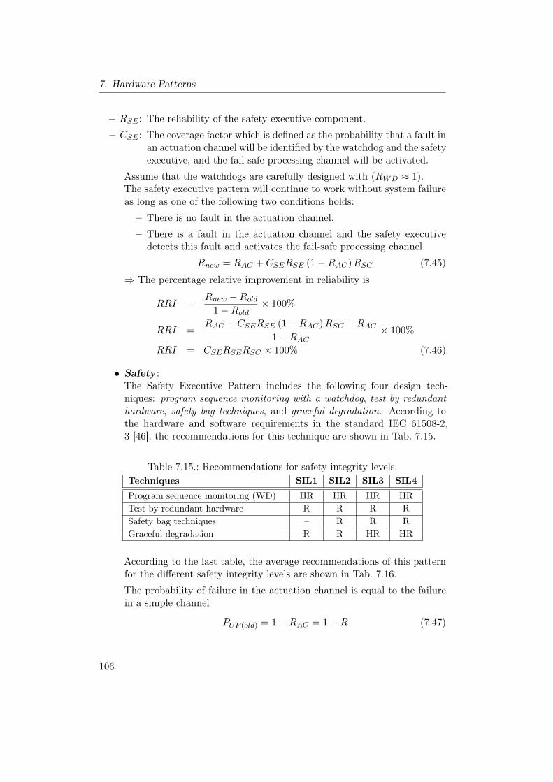
7. Hardware Patterns
− RSE : The reliability of the safety executive component.
− CSE : The coverage factor which is defined as the probability that a fault inan actuation channel will be identified by the watchdog and the safetyexecutive, and the fail-safe processing channel will be activated.
Assume that the watchdogs are carefully designed with (RWD ≈ 1).The safety executive pattern will continue to work without system failureas long as one of the following two conditions holds:
– There is no fault in the actuation channel.
– There is a fault in the actuation channel and the safety executivedetects this fault and activates the fail-safe processing channel.
Rnew = RAC + CSERSE (1−RAC)RSC (7.45)
⇒ The percentage relative improvement in reliability is
RRI =Rnew −Rold
1−Rold× 100%
RRI =RAC + CSERSE (1−RAC)RSC −RAC
1−RAC× 100%
RRI = CSERSERSC × 100% (7.46)
• Safety :The Safety Executive Pattern includes the following four design tech-niques: program sequence monitoring with a watchdog, test by redundanthardware, safety bag techniques, and graceful degradation. According tothe hardware and software requirements in the standard IEC 61508-2,3 [46], the recommendations for this technique are shown in Tab. 7.15.
Table 7.15.: Recommendations for safety integrity levels.Techniques SIL1 SIL2 SIL3 SIL4
Program sequence monitoring (WD) HR HR HR HRTest by redundant hardware R R R RSafety bag techniques – R R RGraceful degradation R R HR HR
According to the last table, the average recommendations of this patternfor the different safety integrity levels are shown in Tab. 7.16.
The probability of failure in the actuation channel is equal to the failurein a simple channel
PUF (old) = 1−RAC = 1−R (7.47)
106
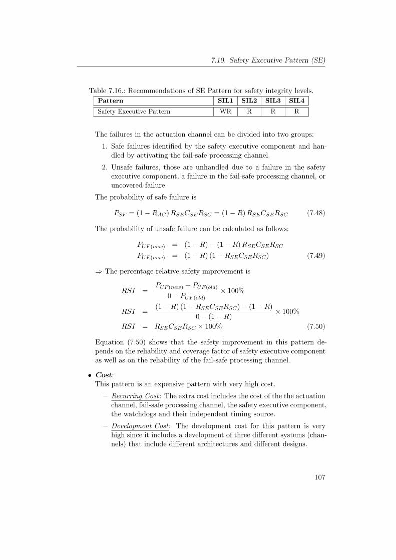
7.10. Safety Executive Pattern (SE)
Table 7.16.: Recommendations of SE Pattern for safety integrity levels.Pattern SIL1 SIL2 SIL3 SIL4
Safety Executive Pattern WR R R R
The failures in the actuation channel can be divided into two groups:
1. Safe failures identified by the safety executive component and han-dled by activating the fail-safe processing channel.
2. Unsafe failures, those are unhandled due to a failure in the safetyexecutive component, a failure in the fail-safe processing channel, oruncovered failure.
The probability of safe failure is
PSF = (1−RAC)RSECSERSC = (1−R)RSECSERSC (7.48)
The probability of unsafe failure can be calculated as follows:
PUF (new) = (1−R)− (1−R)RSECSERSCPUF (new) = (1−R) (1−RSECSERSC) (7.49)
⇒ The percentage relative safety improvement is
RSI =PUF (new) − PUF (old)
0− PUF (old)× 100%
RSI =(1−R) (1−RSECSERSC)− (1−R)
0− (1−R)× 100%
RSI = RSECSERSC × 100% (7.50)
Equation (7.50) shows that the safety improvement in this pattern de-pends on the reliability and coverage factor of safety executive componentas well as on the reliability of the fail-safe processing channel.
• Cost:This pattern is an expensive pattern with very high cost.
– Recurring Cost : The extra cost includes the cost of the the actuationchannel, fail-safe processing channel, the safety executive component,the watchdogs and their independent timing source.
– Development Cost : The development cost for this pattern is veryhigh since it includes a development of three different systems (chan-nels) that include different architectures and different designs.
107
7. Hardware Patterns
• Modifiability :There are two type of possible modifications:
– To modify the actuation channel, the designer should determinewhether the new components need to send stroke messages to thewatchdog or not, which can be done easily.
– One of the main features of this pattern is the centralized safetyprocessing.The safety executive separates the coordinator from thesafety policies to simplify the modification of the safety policy.
• Impact on Execution Time:The actuation channel and the safety executive have different CPUs, dif-ferent memories and run simultaneously in parallel. Therefore, there is noeffect for the safety executive component on the actuation channel, duringthe normal operation, except the execution of the periodic built in tests.
Implementation:
• The actuation channel, safety executive, and the fail-safe processing chan-nel should run separately in parallel on different CPUs and memories.
• The safety-critical information must be protected against data corruption,e.g. by using CRCs or any other method to detect data errors.
• The watchdog component is simple and often implemented as a separatehardware device. It is capable of detecting a variety of hardware andsoftware fault. However, its actual diagnostic coverage depends on theintegrity check implemented in the actuation channel.
• To provide protection from time-based faults, separate timing sourcesmust be used for the watchdog, safety executive, and the two channels.
Consequences and Side Effects:The main drawback of this pattern is the high complexity for implementation.Therefore, it is used for complex and highly safety-critical systems.
Related Patterns:The Safety Executive Pattern is used for complex safety-critical applicationsand it covers a large set of features such as sequence monitoring provided bywatchdog and switch-to-backup as in the fail-safe channel. For simpler systemswith simpler safety requirements, other simpler patterns such as Watchdog Pat-tern, Sanity Check Pattern and Monitor-Actuator Pattern can be used.
108
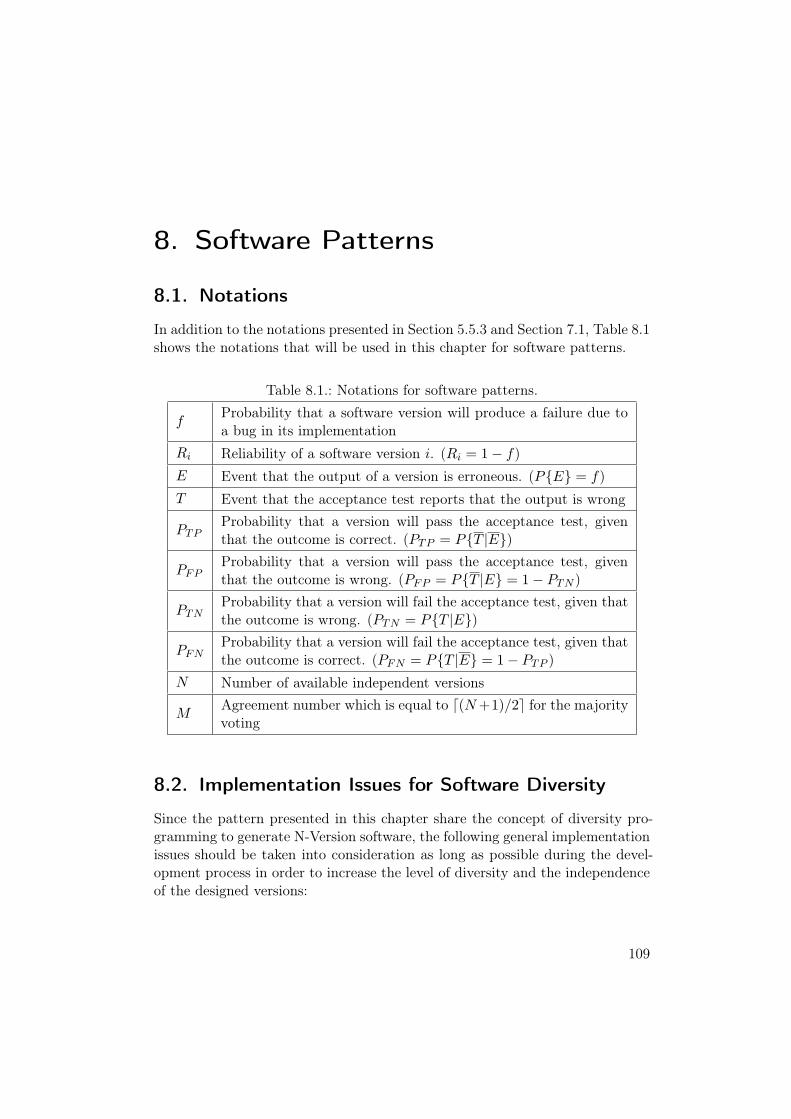
8. Software Patterns
8.1. Notations
In addition to the notations presented in Section 5.5.3 and Section 7.1, Table 8.1shows the notations that will be used in this chapter for software patterns.
Table 8.1.: Notations for software patterns.
fProbability that a software version will produce a failure due toa bug in its implementation
Ri Reliability of a software version i. (Ri = 1− f)E Event that the output of a version is erroneous. (P{E} = f)T Event that the acceptance test reports that the output is wrong
PTPProbability that a version will pass the acceptance test, giventhat the outcome is correct. (PTP = P{T |E})
PFPProbability that a version will pass the acceptance test, giventhat the outcome is wrong. (PFP = P{T |E} = 1− PTN )
PTNProbability that a version will fail the acceptance test, given thatthe outcome is wrong. (PTN = P{T |E})
PFNProbability that a version will fail the acceptance test, given thatthe outcome is correct. (PFN = P{T |E} = 1− PTP )
N Number of available independent versions
MAgreement number which is equal to d(N+1)/2e for the majorityvoting
8.2. Implementation Issues for Software Diversity
Since the pattern presented in this chapter share the concept of diversity pro-gramming to generate N-Version software, the following general implementationissues should be taken into consideration as long as possible during the devel-opment process in order to increase the level of diversity and the independenceof the designed versions:
109
8. Software Patterns
• The use of complete, correct, and carefully documented specifications toprevent an error in specifications from propagating to the versions.
• The use of independent and isolated teams of programmers with diversityin their training and experience.
• The use of diverse algorithms.• The use of diverse programming languages.• The use of diverse compilers, development tools, and test methods.• The use of diverse implementation techniques.
8.3. Assumptions
• The failures in the diverse versions are statistically independent.• All the diverse versions have equal probability of failure⇒ Ri = R = 1−f .• A simple majority voting technique is used in the patterns with voter.• The voter is carefully designed and can be considered as fault-free.
8.4. Voting Techniques
For the patterns that use a voting component, there are many voting techniquesthat can be used to implement this voting component such as:
• Majority Voting : It is the simplest and most common used method that isused to find the output, where at least d(N + 1)/2e variant results agree.
• Plurality Voting (PV): It is a simple voter, that implements M-out-of-Nvoting, where M is less than a strict majority.
• Consensus Voting (CV) [72]: This voting method is used for multi-versionsoftware with small output space. In this method, the result of the largestagreement number is chosen as correct output.
• Maximum Likelihood Voting (MLV) [65]: The voter uses the reliability ofeach version to make a more accurate estimation of the most likely correctresult.
• Adaptive Voting [49]: It introduces an individual weighting factor to eachversion which is later included in the voting procedure. These weightingfactors are dynamically changeable to model and manage different qualitylevels of versions.
110
8.5. N-Version Programming Pattern (NVP)
8.5. N-Version Programming Pattern (NVP)
Other Names:Master-Slave Pattern [22].
Type:Software Pattern.
Abstract:N-Version Programming [13, 11, 25] is a very well known fault-tolerant softwaremethod based on software diversity and fault masking. It is defined as the in-dependent generation of N ≥ 2 functionally equivalent software modules called“versions” from the same initial specification [13]. This pattern includes N pro-grams that are running in parallel to perform the same task on the same inputto produce N outputs. A voter is used in this pattern to produce the correctoutput; it accepts the N results as inputs, and uses these results to determinethe correct output according to a specific voting scheme.
Context:Developing a fault-tolerant software for a highly safety-critical system in a sit-uation where:
• Highly reliable software is needed.
• The high cost for developing multiple implementations can be covered.
• There are available independent N teams to develop the different versions.
• There is a possibility to use N redundant hardware units to execute theseversions in parallel.
Problem:How to overcome the software faults, which may remain after the softwaredevelopment, in order to improve the software reliability and safety.
Pattern Structure:The N-Version Programming Pattern is a well known fault-tolerant approachthat is used for very critical applications due to the high development cost [97].The idea of this pattern is based on the concept of independent generationof functionally equivalent N versions from the same initial specification. Theoutputs of these versions are sent to the voter which executes a voting strategy
111
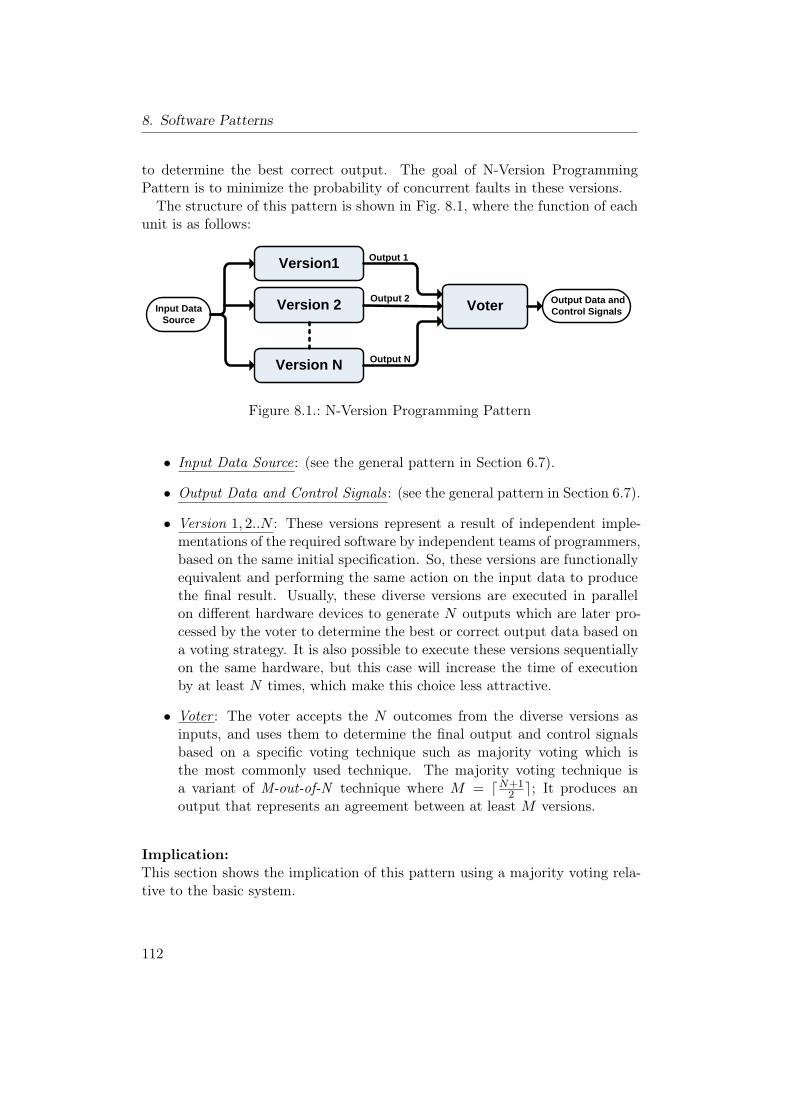
8. Software Patterns
to determine the best correct output. The goal of N-Version ProgrammingPattern is to minimize the probability of concurrent faults in these versions.The structure of this pattern is shown in Fig. 8.1, where the function of each
unit is as follows:
Version1
Version 2Input Data Source
Voter
Version N
Output Data and Control Signals
Output 1
Output 2
Output N
Figure 8.1.: N-Version Programming Pattern
• Input Data Source: (see the general pattern in Section 6.7).
• Output Data and Control Signals: (see the general pattern in Section 6.7).
• Version 1, 2..N : These versions represent a result of independent imple-mentations of the required software by independent teams of programmers,based on the same initial specification. So, these versions are functionallyequivalent and performing the same action on the input data to producethe final result. Usually, these diverse versions are executed in parallelon different hardware devices to generate N outputs which are later pro-cessed by the voter to determine the best or correct output data based ona voting strategy. It is also possible to execute these versions sequentiallyon the same hardware, but this case will increase the time of executionby at least N times, which make this choice less attractive.
• Voter : The voter accepts the N outcomes from the diverse versions asinputs, and uses them to determine the final output and control signalsbased on a specific voting technique such as majority voting which isthe most commonly used technique. The majority voting technique isa variant of M-out-of-N technique where M = dN+1
2 e; It produces anoutput that represents an agreement between at least M versions.
Implication:This section shows the implication of this pattern using a majority voting rela-tive to the basic system.
112
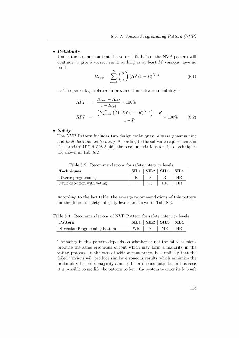
8.5. N-Version Programming Pattern (NVP)
• Reliability :Under the assumption that the voter is fault-free, the NVP pattern willcontinue to give a correct result as long as at least M versions have nofault.
Rnew =N∑i=M
(N
i
)(R)i (1−R)N−i (8.1)
⇒ The percentage relative improvement in software reliability is
RRI =Rnew −Rold
1−Rold× 100%
RRI =
(∑Ni=M
(Ni
)(R)i (1−R)N−i
)−R
1−R× 100% (8.2)
• Safety :The NVP Pattern includes two design techniques: diverse programmingand fault detection with voting. According to the software requirements inthe standard IEC 61508-3 [46], the recommendations for these techniquesare shown in Tab. 8.2.
Table 8.2.: Recommendations for safety integrity levels.Techniques SIL1 SIL2 SIL3 SIL4
Diverse programming R R R HRFault detection with voting – R HR HR
According to the last table, the average recommendations of this patternfor the different safety integrity levels are shown in Tab. 8.3.
Table 8.3.: Recommendations of NVP Pattern for safety integrity levels.Pattern SIL1 SIL2 SIL3 SIL4
N-Version Programming Pattern WR R MR HR
The safety in this pattern depends on whether or not the failed versionsproduce the same erroneous output which may form a majority in thevoting process. In the case of wide output range, it is unlikely that thefailed versions will produce similar erroneous results which minimize theprobability to find a majority among the erroneous outputs. In this case,it is possible to modify the pattern to force the system to enter its fail-safe
113
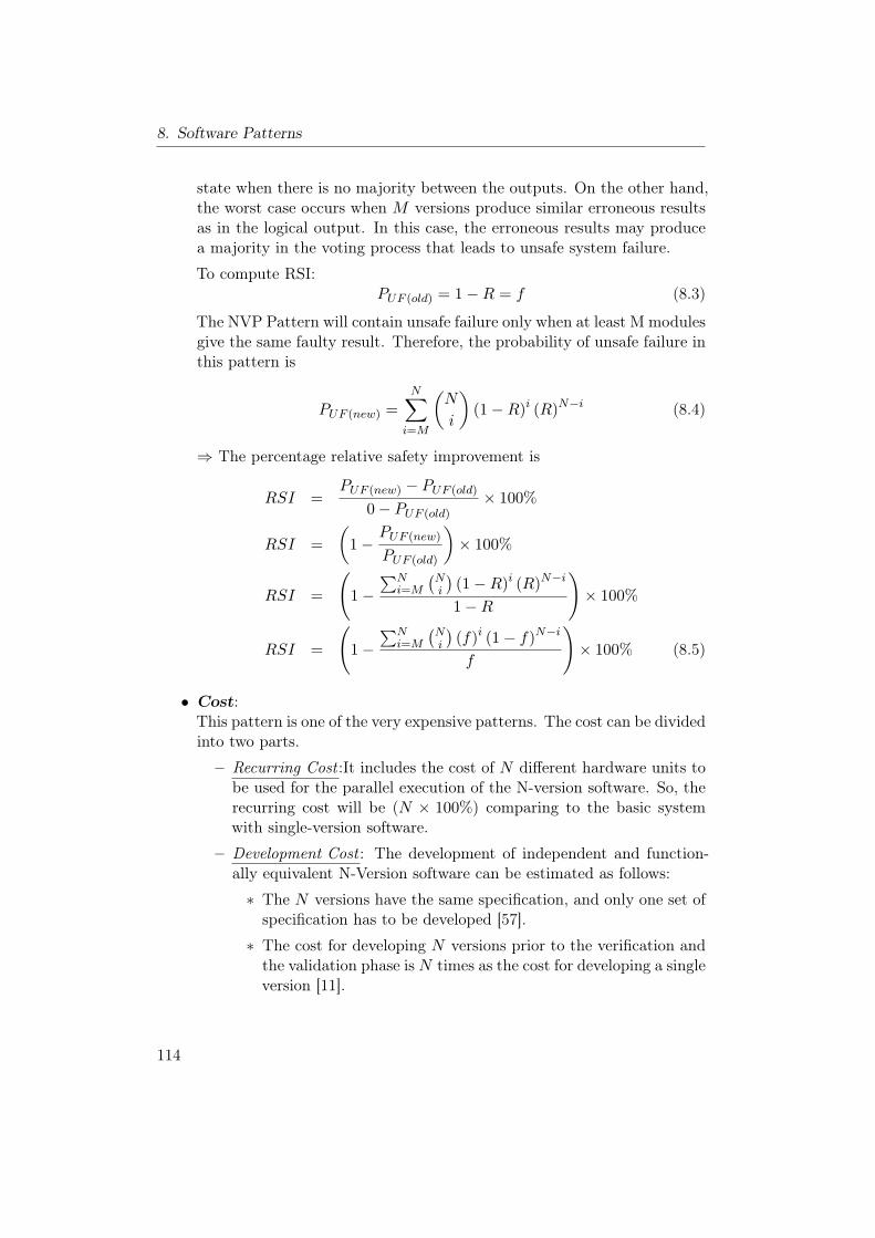
8. Software Patterns
state when there is no majority between the outputs. On the other hand,the worst case occurs when M versions produce similar erroneous resultsas in the logical output. In this case, the erroneous results may producea majority in the voting process that leads to unsafe system failure.
To compute RSI:PUF (old) = 1−R = f (8.3)
The NVP Pattern will contain unsafe failure only when at least M modulesgive the same faulty result. Therefore, the probability of unsafe failure inthis pattern is
PUF (new) =N∑i=M
(N
i
)(1−R)i (R)N−i (8.4)
⇒ The percentage relative safety improvement is
RSI =PUF (new) − PUF (old)
0− PUF (old)× 100%
RSI =(
1−PUF (new)
PUF (old)
)× 100%
RSI =
(1−
∑Ni=M
(Ni
)(1−R)i (R)N−i
1−R
)× 100%
RSI =
(1−
∑Ni=M
(Ni
)(f)i (1− f)N−i
f
)× 100% (8.5)
• Cost:This pattern is one of the very expensive patterns. The cost can be dividedinto two parts.
– Recurring Cost :It includes the cost of N different hardware units tobe used for the parallel execution of the N-version software. So, therecurring cost will be (N × 100%) comparing to the basic systemwith single-version software.
– Development Cost : The development of independent and function-ally equivalent N-Version software can be estimated as follows:
∗ The N versions have the same specification, and only one set ofspecification has to be developed [57].
∗ The cost for developing N versions prior to the verification andthe validation phase is N times as the cost for developing a singleversion [11].
114
8.5. N-Version Programming Pattern (NVP)
∗ The different versions can be used to validate each other, whichwill decrease the cost for verification and validation tools [57].
∗ The management of an N-version project imposes overhead notfound in traditional software development [57].
Exact information about the cost of creating N versions from thesame specification is limited. The estimated practical cost of devel-opment of multi-version software shows that the cost increases sub-linearly with the number of components [33]. And each additionalversion costs about 75− 80% of a single version [68].
• Modifiability :There are three possible modifications
1. Modification of a single version: It is possible to modify a single ver-sion either to remove a newly discovered fault, or to improve a poorlyprogrammed function [12]. In this case, the initial specification re-mains without any modification, and the modification of this versionis similar to the modification of single-version software following astandard fault removal procedure.
2. Modification of all member versions: The reason for this modifica-tion is either to add a new functionality or to improve the overallperformance of the N-version software [12]. In this case, the initialspecification should be modified, and all the N versions should bemodified and tested independently by independent teams to performthe new changes to the affected modules. In general, the modifi-cation of N-version software is remarkably more difficult than themodification of single-version software.
3. Modification of the voter : The separation of the voter from the Nversions allows easy modifications or changes of the voting technique.
• Impact on Execution Time:There are two methods to execute N-version software, either using paral-lel execution which is the most common one, or the sequential execution.In the case of parallel execution on N independent hardware units, thedifferent versions might need different execution time since they are im-plemented by different teams of programmers. Consequently, the voterneeds to wait for all outputs to start the voting algorithm. So, the totaltime of execution is determined by the slowest version in addition to therelatively small time to execute the voting algorithm. In general, if weneglect the voter execution time, then the execution time of the N-versionsoftware is slightly equal to single-version software.
115

8. Software Patterns
In the case of sequential execution, the execution time will increase by Ntimes. This disadvantage makes the sequential execution less attractive,especially for time-critical applications.
Implementation:
• The success of the NVP Pattern depends on the independent developmentof the required N versions and the level of diversity in these versions toavoid the common failures. In order to increase the level of diversityand the independence of the designed versions, the implementation issuespresented in Section 8.2 should be taken into consideration as long aspossible during the development process.
• There are several voting techniques that can be used in this pattern toimplement the voter component (see Section 8.4). The selection of thesuitable technique depends on the data type, deviation in the outputs ofthe versions, type of agreement [63], output space cardinality size, func-tionality of the voter [75], reliability of different versions, and many otherfactors.
Consequences and Side Effects:The main drawbacks of the NVP Pattern are the complexity of developing in-dependent N-versions in addition to the high development cost and the highdependency on the initial specification which may propagates dependent faultsto all versions. The problem of dependent faults in all versions is critical in thispattern for the system safety and reliability.
Related Patterns:The most related pattern is the Recovery Block Pattern which uses diverse soft-ware versions with acceptance tests instead of using a voting algorithm. On theother hand, the N-version programming is used to improve the software relia-bility, and it uses multiple hardware units. Thus, it is possible to combine thispattern with the Heterogeneous Design Pattern for the design of these diversehardware units to deal with the systematic hardware faults. This combinationwill improve the reliability and safety of the hardware as well as the software.
116
8.6. Recovery Block Pattern (RB)
8.6. Recovery Block Pattern (RB)
Other Names:–
Type:Software Pattern.
Abstract:Recovery Block [68, 82, 84, 97] is a very well known fault-tolerant softwaremethod. It is based on fault detection with acceptance tests and backward er-ror recovery to avoid system failures. As in N-Version Programming, the Recov-ery Block Pattern includes N diverse, independent, and functionally equivalentsoftware modules called “versions” from the same initial specification. Thesemodules are classified into primary and N − 1 secondary versions, where theexecution of any version is followed by an acceptance test. The primary version(Block) is firstly executed and followed by its acceptance test. Failure of thetest will result in execution of a secondary alternate version (Recovery Block),which is also followed by an acceptance test. The last step is repeated untileither one alternate passes its acceptance test or all alternates are executedwithout passing the test and an overall system failure is reported.
Context:Developing a fault-tolerant software for a highly safety-critical system in a sit-uation where:
• Highly reliable and safety-critical software is needed.
• There is a possibility to construct an acceptance test to ensure the correctoperation of the software and to detect the possible erroneous output.
• There are available independent N teams to develop the different versions.
• The high cost for developing multiple implementations can be covered.
Problem:How to overcome the software faults, which may remain after the softwaredevelopment, in order to improve the software reliability and safety.
Pattern Structure:Similar to the NVP, Recovery Block Pattern is a well known fault-tolerantapproach that is used for moderately and highly critical applications due to the
117
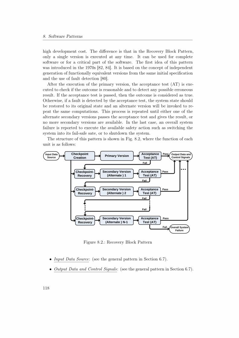
8. Software Patterns
high development cost. The difference is that in the Recovery Block Pattern,only a single version is executed at any time. It can be used for completesoftware or for a critical part of the software. The first idea of this patternwas introduced in the 1970s [82, 84]. It is based on the concept of independentgeneration of functionally equivalent versions from the same initial specificationand the use of fault detection [80].After the execution of the primary version, the acceptance test (AT) is exe-
cuted to check if the outcome is reasonable and to detect any possible erroneousresult. If the acceptance test is passed, then the outcome is considered as true.Otherwise, if a fault is detected by the acceptance test, the system state shouldbe restored to its original state and an alternate version will be invoked to re-peat the same computations. This process is repeated until either one of thealternate secondary versions passes the acceptance test and gives the result, orno more secondary versions are available. In the last case, an overall systemfailure is reported to execute the available safety action such as switching thesystem into its fail-safe sate, or to shutdown the system.The structure of this pattern is shown in Fig. 8.2, where the function of each
unit is as follows:
Checkpoint Creation
Input Data Source
Acceptance Test (AT)
Output Data and Control SignalsPrimary Version
Checkpoint-Recovery
Acceptance Test (AT)
Secondary Version (Alternate ) 1
Acceptance Test (AT)
Secondary Version (Alternate ) 2
Checkpoint-Recovery
Acceptance Test (AT)
Secondary Version (Alternate ) N-1
Overall System Failure
Checkpoint-Recovery
Fail
Pass
Fail
Fail
Fail
Fail
Pass
Pass
Pass
Figure 8.2.: Recovery Block Pattern
• Input Data Source: (see the general pattern in Section 6.7).
• Output Data and Control Signals: (see the general pattern in Section 6.7).
118
8.6. Recovery Block Pattern (RB)
• Checkpoint Creation: In order to provide each alternate with the samedata and the same initial conditions, this component is used to createa checkpoint through storing the input data and the system state be-fore executing the primary version. There are many methods and tech-niques that have been proposed to store the system state such as: recoverycache [82, 84], recoverable procedure [82], and stacked recovery cache [3].These methods differ in the way of storing the data and the size of thedata to be stored, and they include a variation from storing a snapshotof the state of all variables within the system to storing only those valuesthat are about to be changed [97].
• Checkpoint-Recovery : This component is used to rollback the system toits initial state when the primary version or the alternate versions failto pass the acceptance test. This component is invoked before enteringany alternate version, where it takes the information about the storedcheckpoint to switch the system environment to the same point at whichthe primary version started computation.
• Primary and Secondary (Alternate) Versions: These functionally equiva-lent versions represent a result of independent implementations of therequired software by independent teams of programmers, based on thesame initial specification. The primary alternate is the one which is in-tended to be used normally to perform the desired operation [82]. If afault is detected in the primary version, then the alternate secondary ver-sions are executed in turn, until one alternate passes its acceptance test,or no more secondary alternate versions are available.
It is also possible to execute the alternate versions in parallel as in the Dis-tributed Execution of the Recovery Blocks scheme [52, 53]. In this scheme,the different versions are distributed on N different hardware units whereeach unit executes a single version followed by its acceptance test, and theoutput is normally taken from the primary module. If the primary versionfails the acceptance test, the output of the alternate version that passesthe acceptance test can be used, and the roles of primary and secondarycopies are reversed. Since the alternate versions are executed in parallel,the system does not need to store a checkpoint and to roll back whenthere is a failure in one version.
• Acceptance Test (AT): It is the part of the software which is executed onthe exit from the primary and the alternate versions to confirm that theresult is reasonable and to verify the correctness of the calculations basedon the software specification. The acceptance test returns true or false,and it may have several components and may include checks for runtime
119
8. Software Patterns
errors [97] and mechanisms for implicit error detection. The success ofthe recovery block depends on the performance and the quality of theacceptance test. Thus, it should be carefully design and it should besimple, effective, and highly reliable.
Implication:This section shows the implication of this pattern relative to the basic system.
• Reliability :For the success of the recovery block, it must pass the acceptance testwith correct outcome at some stage i, 1 ≤ i ≤ N , which means that thetest fails the stages from 1 to i− 1 and at stage i the outcome is correctand it passes the acceptance test.
Probability{Success at stage i} = P{T}i−1P{E ∩ T}
Rnew =Probability that the RB is successful at some stage i, 1 ≤ i ≤ N .
Rnew =N∑i=1
P{T}i−1P{E∩T} (8.6)
P{T} = P{E}P{T |E}+ P{E}P{T |E}P{T} = fPTN + (1− f)PFN (8.7)
P{E ∩ T} = P{E}P{T |E} = (1− f)PFN (8.8)
P{E ∩ T} = P{E} − P{E ∩ T}P{E ∩ T} = (1− f)− (1− f)PFNP{E ∩ T} = (1− f)PTP (8.9)
Under the assumption of (f = 1−R) and by substituting Equation (8.9)and Equation (8.7) in Equation (8.6) we obtain
Rnew =N∑i=1
((1−R)PTN +RPFN )i−1 (RPTP ) (8.10)
Equation (8.10) shows that the success of the recovery block depends on(PTN ) and the (PTP ) which are determined by the quality of the accep-tance test. Thus, the carefully designed acceptance test is a key factor for
120
8.6. Recovery Block Pattern (RB)
the success of this scheme.
⇒ The percentage relative improvement in software reliability is
RRI =Rnew −Rold
1−Rold× 100%
RRI =
(N∑i=1
((1−R)PTN +RPFN )i−1 (RPTP )
)−R
1−R× 100% (8.11)
• Safety :The RB Pattern includes three design techniques: diverse programming,fault detection and diagnosis (AT), and recovery block. According to thesoftware requirements in the standard IEC 61508-3 [46], the recommenda-tions for these techniques are shown in Tab. 8.4.
Table 8.4.: Recommendations for safety integrity levels.Techniques SIL1 SIL2 SIL3 SIL4
Diverse programming R R R HRFault detection and diagnosis – R HR HRRecovery block R R R R
According to the last table, the average recommendations of this patternfor the different safety integrity levels are shown in Tab. 8.5.
Table 8.5.: Recommendations of RB Pattern for safety integrity levels.Pattern SIL1 SIL2 SIL3 SIL4
Recovery Block Pattern R R R HR
In the case of unsafe failure in the recovery block pattern, it passes theacceptance test with erroneous outcome at some stage i, 1 ≤ i ≤ N , whichmeans that the test fails the stages from 1 to i − 1 and at stage i theoutcome of the version i is erroneous and it passes the acceptance test(false positive case).
Probability{a false positive case at stage i} = P{T}i−1P{E ∩ T}
PUF (new) =Probability that the RB pattern fails unsafely at some stage
121
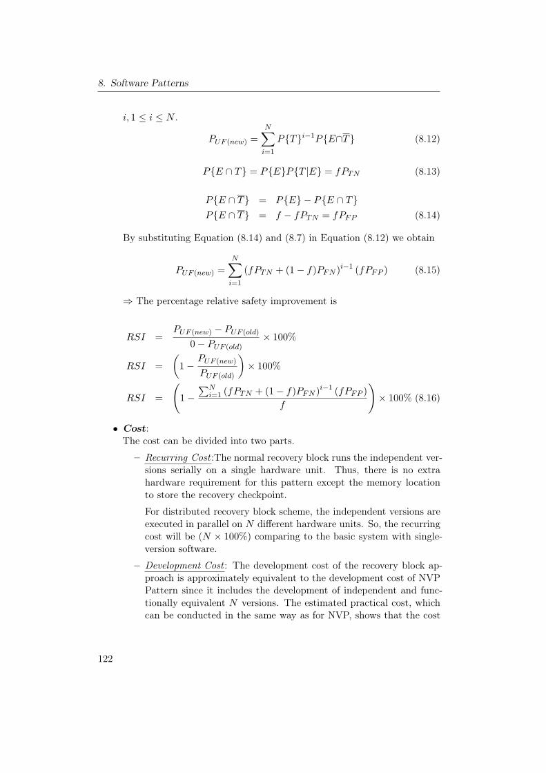
8. Software Patterns
i, 1 ≤ i ≤ N .
PUF (new) =N∑i=1
P{T}i−1P{E∩T} (8.12)
P{E ∩ T} = P{E}P{T |E} = fPTN (8.13)
P{E ∩ T} = P{E} − P{E ∩ T}P{E ∩ T} = f − fPTN = fPFP (8.14)
By substituting Equation (8.14) and (8.7) in Equation (8.12) we obtain
PUF (new) =N∑i=1
(fPTN + (1− f)PFN )i−1 (fPFP ) (8.15)
⇒ The percentage relative safety improvement is
RSI =PUF (new) − PUF (old)
0− PUF (old)× 100%
RSI =(
1−PUF (new)
PUF (old)
)× 100%
RSI =
(1−
∑Ni=1 (fPTN + (1− f)PFN )i−1 (fPFP )
f
)× 100% (8.16)
• Cost:The cost can be divided into two parts.
– Recurring Cost :The normal recovery block runs the independent ver-sions serially on a single hardware unit. Thus, there is no extrahardware requirement for this pattern except the memory locationto store the recovery checkpoint.
For distributed recovery block scheme, the independent versions areexecuted in parallel on N different hardware units. So, the recurringcost will be (N × 100%) comparing to the basic system with single-version software.
– Development Cost : The development cost of the recovery block ap-proach is approximately equivalent to the development cost of NVPPattern since it includes the development of independent and func-tionally equivalent N versions. The estimated practical cost, whichcan be conducted in the same way as for NVP, shows that the cost
122
8.6. Recovery Block Pattern (RB)
increases sublinearly with the number of components [33]. And eachadditional version costs about 75−80% of a single version [68]. More-over, this pattern includes extra cost for developing an effective ac-ceptance test, which has great impact on the success of this pattern.
• Modifiability :There are three possible modifications
1. Modification of a single version: It is possible to modify a single ver-sion either to remove a newly discovered fault, or to improve a poorlyprogrammed function [12]. In this case, the initial specification re-mains without any modification, and the modification of this versionis similar to the modification of single-version software following astandard fault removal procedure.
2. Modification of all member versions: The reason for this modifica-tion is either to add a new functionality or to improve the overallperformance of the N-version software [12]. In this case, the initialspecification should be modified, and all the N versions should bemodified and tested independently by independent teams to performthe new changes to the affected modules. In general, the modifi-cation of N-version software is remarkably more difficult than themodification of single-version software.
3. Modification of the acceptance test : The acceptance test can be con-sidered as independent module. Thus, it can be easily modified with-out any influence on the different versions.
• Impact on Execution Time:The total execution time of a single version followed by its AT is
T = tSV + tAT (8.17)
Where:− tSV : the execution time of a single version.− tAT : the execution time of the acceptance test.
Most of the time, only the primary alternate of the recovery block isexecuted, which keeps the run-time overhead of the recovery block to aminimum value which represents the best execution time (T ) [85]. Inthe worst case, all the alternates are executed without getting a reason-able result. Under the assumption that the different versions have equalexecution times, the worst case execution time will be N × T .
123
8. Software Patterns
Consequently, the worst case execution time of the RB Pattern can beconsidered as the main disadvantage which makes it less suitable for time-critical applications.
Implementation:The success of the RB pattern depends on two factors [57]:
1. The quality of the acceptance test. Therefore, the acceptance test shouldbe carefully designed to detected most of the possible software faults,which will improve the reliability of the recovery blocks.
2. The independent development of the required N versions and the levelof diversity in these versions to avoid the common failures. In order toincrease the level of diversity and the independence of the developed ver-sions, the implementation issues presented in Section 8.2 should be takeninto consideration as long as possible during the development process.
Consequences and Side Effects:The main drawbacks of the RB are the high dependency on the quality of theacceptance test and the time influence of the sequential execution which mayinclude a situation with interrupted service during recovery. Also, It has com-mon drawbacks with the NVP Pattern, such as the complexity of developingindependent N-versions, the high development cost, and the high dependencyon the initial specification which may propagate software bugs to all versions.
Related Patterns:The Recovery Block Pattern is normally combined with the Watchdog Patternto test the software versions for timeout condition and to provide program se-quence monitoring. The distributed Recovery Block runs the alternate versionsin parallel on different hardware units. Thus, it is possible to combine the dis-tributed Recovery Block with the Heterogeneous Design Pattern for the designof these diverse hardware units to deal with the systematic hardware faults.
124
8.7. Acceptance Voting Pattern (AV)
8.7. Acceptance Voting Pattern (AV)
Other Names:–
Type:Software Pattern.
Abstract:Acceptance Voting Pattern [10] is a hybrid pattern that incorporates the NVPPattern with the acceptance test used by the RB Pattern. Similar to the NVP,this pattern is based on the independent generation of N ≥ 2 functionally equiv-alent software modules called “versions” from the same initial specification [13].This pattern includes N programs that are running in parallel to perform thesame task on the same input to produce N outputs. The output of each ver-sion is presented to an acceptance test to check it for correctness. The outputsthat pass the acceptance test are used as inputs to a dynamic voter, which isexecuted to produce the correct output according to a voting scheme.
Context:Developing a fault-tolerant software for a highly safety-critical system in a sit-uation where:
• Highly reliable software is needed.
• There is a possibility to construct an acceptance test to ensure the correctoperation of the software and to detect the possible erroneous output.
• The high cost for developing multiple implementations can be covered.
• There are available independent N teams to develop the different versions.
• There is a possibility to use N redundant hardware units to execute theseversions in parallel.
Problem:How to overcome the software faults, which may remain after the softwaredevelopment, in order to improve the software reliability and safety.
Pattern Structure:The Acceptance Voting Pattern represents a combination of the fault detectionscheme provided by the acceptance test and the fault masking scheme provided
125
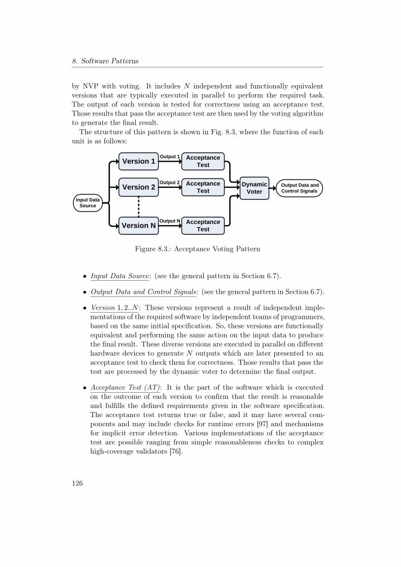
8. Software Patterns
by NVP with voting. It includes N independent and functionally equivalentversions that are typically executed in parallel to perform the required task.The output of each version is tested for correctness using an acceptance test.Those results that pass the acceptance test are then used by the voting algorithmto generate the final result.The structure of this pattern is shown in Fig. 8.3, where the function of each
unit is as follows:
Version 1
Version 2Input Data
Source
Dynamic Voter
Version N
Output Data and Control Signals
Acceptance Test
Acceptance Test
Acceptance Test
Output 1
Output 2
Output N
Figure 8.3.: Acceptance Voting Pattern
• Input Data Source: (see the general pattern in Section 6.7).
• Output Data and Control Signals: (see the general pattern in Section 6.7).
• Version 1, 2..N : These versions represent a result of independent imple-mentations of the required software by independent teams of programmers,based on the same initial specification. So, these versions are functionallyequivalent and performing the same action on the input data to producethe final result. These diverse versions are executed in parallel on differenthardware devices to generate N outputs which are later presented to anacceptance test to check them for correctness. Those results that pass thetest are processed by the dynamic voter to determine the final output.
• Acceptance Test (AT): It is the part of the software which is executedon the outcome of each version to confirm that the result is reasonableand fulfills the defined requirements given in the software specification.The acceptance test returns true or false, and it may have several com-ponents and may include checks for runtime errors [97] and mechanismsfor implicit error detection. Various implementations of the acceptancetest are possible ranging from simple reasonableness checks to complexhigh-coverage validators [76].
126
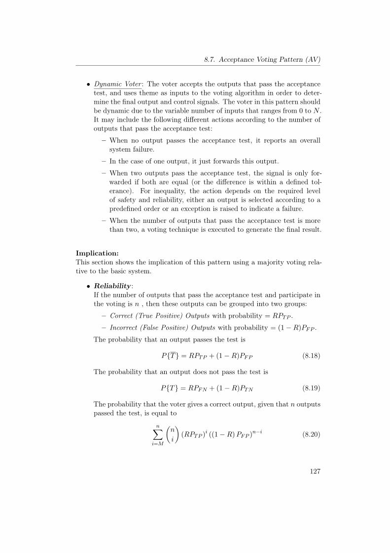
8.7. Acceptance Voting Pattern (AV)
• Dynamic Voter : The voter accepts the outputs that pass the acceptancetest, and uses theme as inputs to the voting algorithm in order to deter-mine the final output and control signals. The voter in this pattern shouldbe dynamic due to the variable number of inputs that ranges from 0 to N .It may include the following different actions according to the number ofoutputs that pass the acceptance test:
– When no output passes the acceptance test, it reports an overallsystem failure.
– In the case of one output, it just forwards this output.
– When two outputs pass the acceptance test, the signal is only for-warded if both are equal (or the difference is within a defined tol-erance). For inequality, the action depends on the required levelof safety and reliability, either an output is selected according to apredefined order or an exception is raised to indicate a failure.
– When the number of outputs that pass the acceptance test is morethan two, a voting technique is executed to generate the final result.
Implication:This section shows the implication of this pattern using a majority voting rela-tive to the basic system.
• Reliability :If the number of outputs that pass the acceptance test and participate inthe voting is n , then these outputs can be grouped into two groups:
– Correct (True Positive) Outputs with probability = RPTP .
– Incorrect (False Positive) Outputs with probability = (1−R)PFP .
The probability that an output passes the test is
P{T} = RPTP + (1−R)PFP (8.18)
The probability that an output does not pass the test is
P{T} = RPFN + (1−R)PTN (8.19)
The probability that the voter gives a correct output, given that n outputspassed the test, is equal to
n∑i=M
(n
i
)(RPTP )i ((1−R)PFP )n−i (8.20)
127
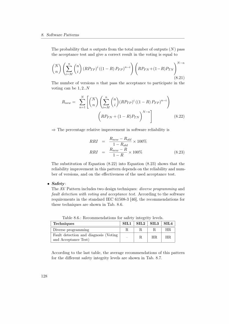
8. Software Patterns
The probability that n outputs from the total number of outputs (N) passthe acceptance test and give a correct result in the voting is equal to
(N
n
)( n∑i=M
(n
i
)(RPTP )i ((1−R)PFP )n−i
)(RPFN+(1−R)PTN
)N−n(8.21)
The number of versions n that pass the acceptance to participate in thevoting can be 1, 2..N
Rnew =N∑n=1
[(N
n
)( n∑i=M
(n
i
)(RPTP )i ((1−R)PFP )n−i
)(RPFN + (1−R)PTN
)N−n](8.22)
⇒ The percentage relative improvement in software reliability is
RRI =Rnew −Rold
1−Rold× 100%
RRI =Rnew −R
1−R× 100% (8.23)
The substitution of Equation (8.22) into Equation (8.23) shows that thereliability improvement in this pattern depends on the reliability and num-ber of versions, and on the effectiveness of the used acceptance test.
• Safety :The AV Pattern includes two design techniques: diverse programming andfault detection with voting and acceptance test. According to the softwarerequirements in the standard IEC 61508-3 [46], the recommendations forthese techniques are shown in Tab. 8.6.
Table 8.6.: Recommendations for safety integrity levels.Techniques SIL1 SIL2 SIL3 SIL4
Diverse programming R R R HRFault detection and diagnosis (Votingand Acceptance Test) – R HR HR
According to the last table, the average recommendations of this patternfor the different safety integrity levels are shown in Tab. 8.7.
128

8.7. Acceptance Voting Pattern (AV)
Table 8.7.: Recommendations of AV Pattern for safety integrity levels.Pattern SIL1 SIL2 SIL3 SIL4
Acceptance Voting Pattern WR R MR HR
The Probability that the voter gives an erroneous output, given that noutputs passed the test, is equal to
M−1∑i=0
(n
i
)((1− f)PTP )i (fPFP )n−i (8.24)
The probability that n outputs from the total number of outputs (N) passthe acceptance test and give an erroneous result in the voting is equal to(N
n
)(M−1∑i=0
(n
i
)((1− f)PTP )i (fPFP )n−i
)((1− f)PFN+fPTN
)N−n(8.25)
The number of versions n that pass the acceptance to participate in thevoting can be 1, 2..N . Therefore, the probability that the AV fails unsafelyis equal to the probability that the voter finds a majority between theerroneous results
PUF (new) =N∑n=1
[(N
n
)(M−1∑i=0
(n
i
)((1− f)PTP )i (fPFP )n−i
)(
(1− f)PFN + fPTN
)N−n](8.26)
⇒ The percentage relative safety improvement is
RSI =PUF (new) − PUF (old)
0− PUF (old)× 100%
RSI =(
1−PUF (new)
f
)× 100%
(8.27)
• Cost:This pattern is resulting in high costs which can be divided into two parts.
– Recurring Cost : It includes the cost of N different hardware unitsto be used for the parallel execution of the N-version software. So,the recurring cost will be (N ×100%) comparing to the basic systemwith single-version software.
129
8. Software Patterns
– Development Cost : The development cost of the AV Pattern is ap-proximately equivalent to the development cost of the NVP Patternsince it includes the development of independent and functionallyequivalent N versions. The estimated practical cost, which can beconducted in the same way as for NVP, shows that the cost increasessublinearly with the number of components [33]. And each additionalversion costs about 75− 80% of a single version [68]. Moreover, thispattern includes extra cost for developing an effective acceptancetest.
• Modifiability :There are four possible modifications
1. Modification of a single version: It is possible to modify a single ver-sion either to remove a newly discovered fault, or to improve a poorlyprogrammed function [12]. In this case, the initial specification re-mains without any modification, and the modification of this versionis similar to the modification of single-version software following astandard fault removal procedure.
2. Modification of all member versions: The reason for this modifica-tion is either to add a new functionality or to improve the overallperformance of the N-version software [12]. In this case, the initialspecification should be modified, and all the N versions should bemodified and tested independently by independent teams to performthe new changes to the affected modules. In general, the modifi-cation of N-version software is remarkably more difficult than themodification of single-version software.
3. Modification of the acceptance test : The acceptance test can be con-sidered as independent module. Thus, it can be easily modified with-out any influence on the different versions or the voter.
4. Modification of the dynamic voter : The separation of the voter fromthe N versions and the acceptance test allows easy modifications orchanges of the voting technique.
• Impact on Execution Time:The diverse software versions in this pattern are executed in parallel, ide-ally on N independent hardware devices. As the execution times of thesesoftware versions might differ since they are implemented independentlyby different teams of programmers, the voter has to wait for the outputsof all versions to be checked by the acceptance test before applying thevoting algorithm. Thus, the total execution time is determined by the
130
8.7. Acceptance Voting Pattern (AV)
slowest version in addition to the typically relatively small time to exe-cute the acceptance test and the voting algorithm. In general, if we canneglect the execution time of the acceptance test and the voter, then theexecution time of this pattern is slightly equal to single-version software.
Implementation:The success of the AV Pattern depends on three factors:
1. The quality of the acceptance. Thus, it should be carefully designed todetected most of the possible software faults.
2. The independent development of the required N versions and the levelof diversity in these versions to avoid the common failures. In order toincrease the level of diversity and the independence of the developed ver-sions, the implementation issues presented in Section 8.2 should be takeninto consideration as long as possible during the development process.
3. The use of a suitable voting technique. There are several voting techniquesthat can be used in this pattern to implement the dynamic voter compo-nent (see Section 8.4). The selection of the suitable technique dependson the data type, deviation in the outputs of the versions, type of agree-ment [63], output space cardinality size, functionality of the voter [75],reliability of different versions, and many other factors.
Consequences and Side Effects:Similar to the original N-version programming approach, the drawbacks of theAV Pattern are seen in the effort of developing N diverse software versions in ad-dition to the high dependency on the initial specification which may propagatefaults to all versions. With respect to safety, the problem of dependent faultsin all versions is less critical in this pattern since the acceptance test representsan additional measure to detect these faults.
Related Patterns:As the AV Pattern is executed on different hardware devices, it is possible tocombine this pattern with the Heterogeneous Design Pattern for the design ofdiverse hardware units that will be able to cope with systematic hardware faults.
131
8. Software Patterns
8.8. N-Self Checking Programming Pattern (NSCP)
Other Names:–
Type:Software Pattern.
Abstract:The N-Self Checking Programming is one of the most costly fault-tolerant soft-ware methods. It is based on software design diversity and self-checking pro-vided by adding redundancy to a program so that it can check its own dynamicbehavior during execution [59]. This pattern includes an independent genera-tion of N ≥ 4 functionally equivalent software modules called “versions” fromthe same initial specification. These versions are arranged into groups calledcomponents, in which each component consists of two versions and a compar-ison algorithm to compare the results of two versions for correctness. Duringthe execution, one component is working as an active component to deliver therequired service, while the other components are hot spares. In order to pro-vide a fault tolerance for a single fault, at least 4 versions must be executedon 4 hardware units, which represents the highest cost comparing to the othermethods.
Context:Developing a fault-tolerant software for a highly safety-critical system in a sit-uation where:
• Highly reliable software is needed.
• The high cost for developing multiple implementations can be covered.
• There are available independent N teams to develop the different versions.
• There is a possibility to use N redundant hardware units to execute theseversions in parallel.
Problem:How to overcome the software faults, which may remain after the software de-velopment, in order to improve the software reliability and safety.
Pattern Structure:The NSCP Pattern is a well known fault-tolerant approach that is based on
132
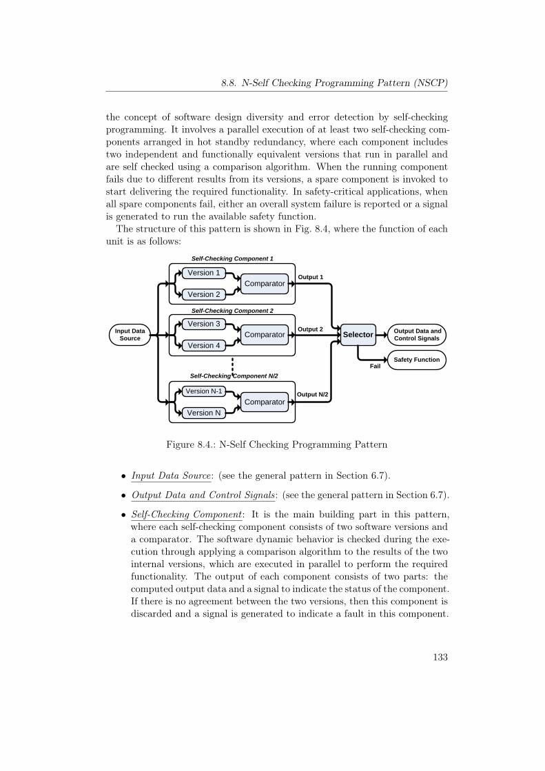
8.8. N-Self Checking Programming Pattern (NSCP)
the concept of software design diversity and error detection by self-checkingprogramming. It involves a parallel execution of at least two self-checking com-ponents arranged in hot standby redundancy, where each component includestwo independent and functionally equivalent versions that run in parallel andare self checked using a comparison algorithm. When the running componentfails due to different results from its versions, a spare component is invoked tostart delivering the required functionality. In safety-critical applications, whenall spare components fail, either an overall system failure is reported or a signalis generated to run the available safety function.The structure of this pattern is shown in Fig. 8.4, where the function of each
unit is as follows:
Version 1
Version 2Comparator
Version 3
Version 4Comparator
Version N-1
Version NComparator
Input Data Source Selector Output Data and
Control Signals
Safety Function
Self-Checking Component 1
Self-Checking Component 2
Self-Checking Component N/2
Output 1
Output 2
Output N/2
Fail
Figure 8.4.: N-Self Checking Programming Pattern
• Input Data Source: (see the general pattern in Section 6.7).
• Output Data and Control Signals: (see the general pattern in Section 6.7).
• Self-Checking Component : It is the main building part in this pattern,where each self-checking component consists of two software versions anda comparator. The software dynamic behavior is checked during the exe-cution through applying a comparison algorithm to the results of the twointernal versions, which are executed in parallel to perform the requiredfunctionality. The output of each component consists of two parts: thecomputed output data and a signal to indicate the status of the component.If there is no agreement between the two versions, then this component isdiscarded and a signal is generated to indicate a fault in this component.
133
8. Software Patterns
• Version 1, 2..N : These versions represent a result of independent imple-mentations of the required software by independent teams of programmers,based on the same initial specification. So, these versions are functionallyequivalent and performing the same action on the input data to producethe final result. Typically, the number of versions N is an even number inorder to group theme in pairs to construct N/2 self-checking components.
• Comparator : This part is used in each self-checking component as amethod for fault detection. It applies a comparison algorithm to theresults of two versions in order to check theme for correctness. If thereis an agreement between the two results, then it generates a valid signaland delivers the result to the selector. If there is no agreement, the resultof the component is discarded and a signal is sent to indicate a failure inthis component. The same comparison algorithm is normally used in allcomponents. Nevertheless, the design diversity could be also applied todevelop a separate comparator for each component.
• Selector : It is a simple module used to switch between the self-checkingcomponents in hot standby redundancy mode. It receives a status signaland output data from each component. If there is a disagreement signalfrom the acting component, then it switches to the next spare component.If the selector reaches the last component without getting an agreement,then it issues a signal to start executing the available safety function.
• Safety Function: It includes the actions to be conducted in the case offailure in all components. It may include different actions that range fromswitching the system into its fail-safe sate to a complex safety algorithmthat involves a predefined sequence of safety steps.
Implication:This section shows the implication of this pattern using a majority voting rela-tive to the basic system.
• Reliability :We will use the following notations for this pattern:
− Cj : The self-checking component number j.
− RC : The reliability of a self-checking component.
− EC : The event that a self-checking component fails.
For the success of the NSCP, the comparator has to find an agreementat some component Cj , 1 ≤ j ≤ N/2, which means that the components
134
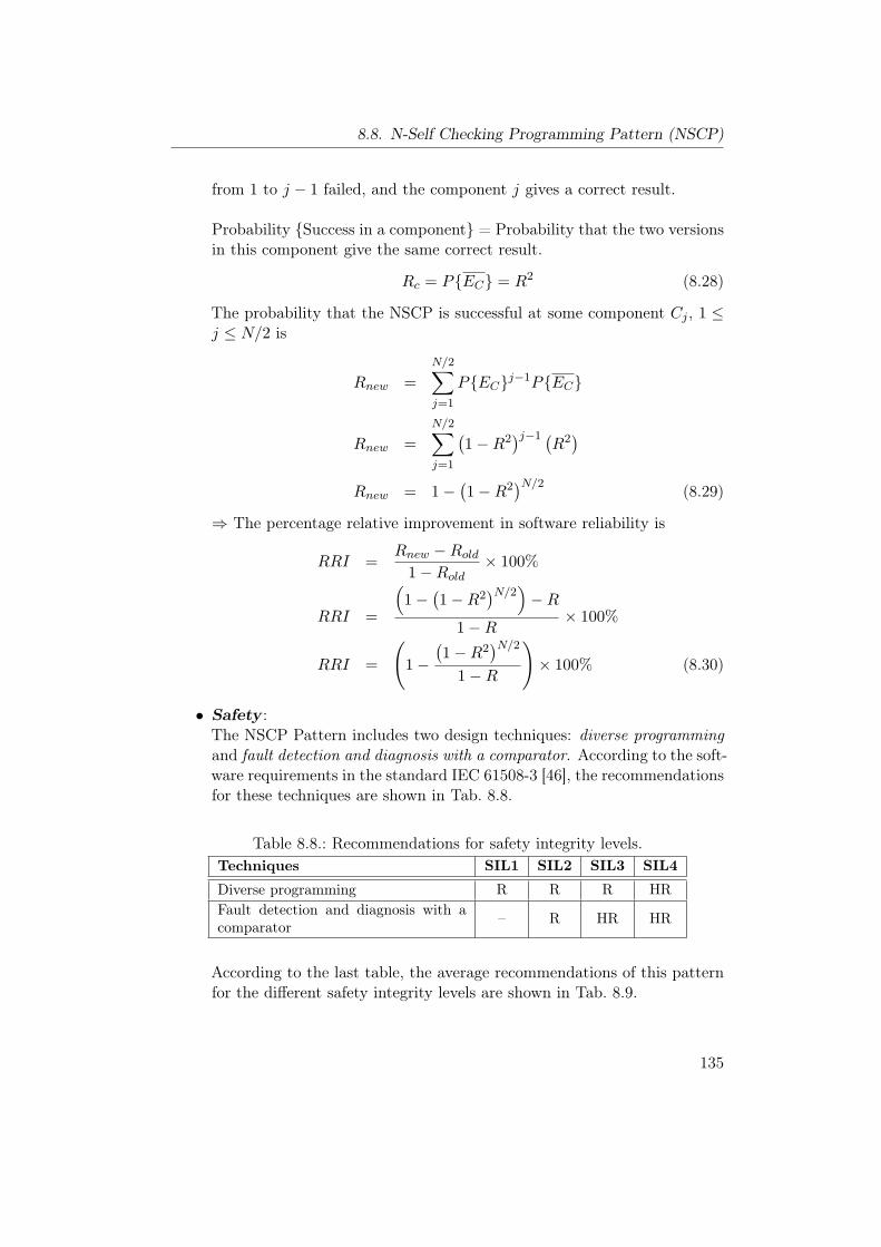
8.8. N-Self Checking Programming Pattern (NSCP)
from 1 to j − 1 failed, and the component j gives a correct result.
Probability {Success in a component} = Probability that the two versionsin this component give the same correct result.
Rc = P{EC} = R2 (8.28)
The probability that the NSCP is successful at some component Cj , 1 ≤j ≤ N/2 is
Rnew =N/2∑j=1
P{EC}j−1P{EC}
Rnew =N/2∑j=1
(1−R2
)j−1 (R2)
Rnew = 1−(1−R2
)N/2 (8.29)
⇒ The percentage relative improvement in software reliability is
RRI =Rnew −Rold
1−Rold× 100%
RRI =
(1−
(1−R2
)N/2)−R1−R
× 100%
RRI =
(1−
(1−R2
)N/21−R
)× 100% (8.30)
• Safety :The NSCP Pattern includes two design techniques: diverse programmingand fault detection and diagnosis with a comparator. According to the soft-ware requirements in the standard IEC 61508-3 [46], the recommendationsfor these techniques are shown in Tab. 8.8.
Table 8.8.: Recommendations for safety integrity levels.Techniques SIL1 SIL2 SIL3 SIL4
Diverse programming R R R HRFault detection and diagnosis with acomparator – R HR HR
According to the last table, the average recommendations of this patternfor the different safety integrity levels are shown in Tab. 8.9.
135
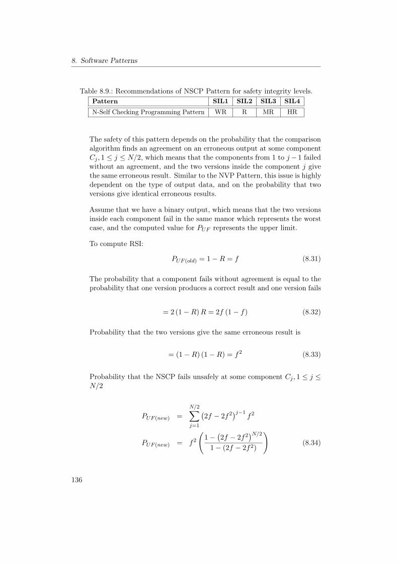
8. Software Patterns
Table 8.9.: Recommendations of NSCP Pattern for safety integrity levels.Pattern SIL1 SIL2 SIL3 SIL4
N-Self Checking Programming Pattern WR R MR HR
The safety of this pattern depends on the probability that the comparisonalgorithm finds an agreement on an erroneous output at some componentCj , 1 ≤ j ≤ N/2, which means that the components from 1 to j− 1 failedwithout an agreement, and the two versions inside the component j givethe same erroneous result. Similar to the NVP Pattern, this issue is highlydependent on the type of output data, and on the probability that twoversions give identical erroneous results.
Assume that we have a binary output, which means that the two versionsinside each component fail in the same manor which represents the worstcase, and the computed value for PUF represents the upper limit.
To compute RSI:
PUF (old) = 1−R = f (8.31)
The probability that a component fails without agreement is equal to theprobability that one version produces a correct result and one version fails
= 2 (1−R)R = 2f (1− f) (8.32)
Probability that the two versions give the same erroneous result is
= (1−R) (1−R) = f2 (8.33)
Probability that the NSCP fails unsafely at some component Cj , 1 ≤ j ≤N/2
PUF (new) =N/2∑j=1
(2f − 2f2
)j−1f2
PUF (new) = f2
(1−
(2f − 2f2
)N/21− (2f − 2f2)
)(8.34)
136
8.8. N-Self Checking Programming Pattern (NSCP)
⇒ The percentage relative safety improvement is
RSI =PUF (new) − PUF (old)
0− PUF (old)× 100%
RSI =(
1−PUF (new)
f
)× 100%
RSI =
(1− f
(1−
(2f − 2f2
)N/21− (2f − 2f2)
))× 100%
(8.35)
• Cost:The cost can be divided into two parts.
– Recurring Cost :It includes the cost of N different hardware units tobe used for the parallel execution of the N-version software. So, therecurring cost will be (N × 100%) comparing to the basic systemwith single-version software. Moreover, the recurring cost will alsoinclude the cost of the comparator and selector unit.
– Development Cost : The development cost of the NSCP is approxi-mately equivalent to the development cost of the NVP Pattern sinceit includes the development of independent and functionally equiv-alent N versions. The estimated practical cost, which can be con-ducted in the same way as for NVP, shows that the cost increasessublinearly with the number of components [33]. And each addi-tional version costs about 75− 80% of a single version [68].Moreover,this pattern includes extra cost for developing the comparator andselector unit.
In general, this pattern is considered as the most expensive among thepatterns that share the principle of diversity programming. To provide afault tolerance for a single fault, it needs 4 versions to run on 4 hardwaremodules in parallel, which is considered as the highest cost.
• Modifiability :There are three possible modifications
1. Modification of a single version: It is possible to modify a single ver-sion either to remove a newly discovered fault, or to improve a poorlyprogrammed function [12]. In this case, the initial specification re-mains without any modification, and the modification of this versionis similar to the modification of single-version software following astandard fault removal procedure.
137
8. Software Patterns
2. Modification of all member versions: The reason for this modifica-tion is either to add a new functionality or to improve the overallperformance of the N-version software [12]. In this case, the initialspecification should be modified, and all the N versions should bemodified and tested independently by independent teams to performthe new changes to the affected modules. In general, the modifi-cation of N-version software is remarkably more difficult than themodification of single-version software.
3. Modification of the comparator : The separation of the comparatormodule from the N versions allows easy modifications or changes ofthe voting technique.
Besides the previous possible major modifications, there is a possibility tomodify the self-checking components to rearrange the different versions.The best two versions can be grouped in the same component to providea strong one that can be activated most of the time with high reliability.
• Impact on Execution Time:The independent versions, which are executed in parallel, might need dif-ferent execution time since they are implemented by different teams ofprogrammers. As the comparator needs to wait for the results of the twoversions to start the comparison algorithm, the total execution time for asingle component is determined by the slowest version in this componentand the relatively small time to execute the comparison algorithm.
The spare self-checking components are working in a hot standby modeand do not need any time for booting in the presence of a fault in theacting component. In the worst case, this mode has the least amount ofinfluence on the time of execution since it just includes the small time toswitch from the acting component to another spare.
In general, if we neglect the execution time of the comparator and thetime for switching, then the execution time of the NSCP method is slightlyequal to single-version software.
Implementation:
• The parallel execution of the components necessitates a consistency of in-puts and outputs [59]. Thus, a consistency mechanism should be includedin the implementation of this pattern to provide synchronization in inputsand outputs.
• The comparator and selector component should be carefully designed toprovide an efficient comparison and fast switching.
138
8.8. N-Self Checking Programming Pattern (NSCP)
• The success of the NSCP Pattern depends on the independent develop-ment of the required N versions and the level of diversity in these versionsto avoid the common failures. In order to increase the level of diversityand the independence of the designed versions, the implementation issuespresented in Section 8.2 should be taken into consideration as long aspossible during the development process.
• The implementation of the self-checking component in the original pro-posed approach [59] includes two methods: the use of two versions anda comparison algorithm as listed above, or the use of a single version fol-lowed by an acceptance test. Actually, the second methods is identical tothe distributed recovery block approach, in which the different versionsare executed in parallel and followed by the execution of the acceptancetests to check the correctness of versions.
Consequences and Side Effects:The NSCP Pattern has the following drawbacks:
• High dependency on the initial specifications that may propagate faultsto all versions.
• The high number of diverse versions and hardware modules used compar-ing to the other patterns that tolerate the same number of faults.
• The complexity of developing N independent and functionally equivalentversions.
Related Patterns:The NSCP Pattern is used to improve the software reliability by executing thediverse versions in parallel. Thus, it is possible to combine this pattern withthe Heterogeneous Design Pattern for the design of diverse hardware units todeal with the systematic hardware faults.
139
8. Software Patterns
8.9. Recovery Block with Backup Voting Pattern(RBBV)
Other Names:–Type:Software Pattern.
Abstract:The Recovery Block with Backup Voting [8] is a hybrid pattern that incorpo-rates the idea of the classical RB with the NVP to improve the reliability ofthe classical RB in those situations where it is difficult to construct an effec-tive acceptance test. This software pattern includes N diverse, independent,and functionally equivalent software modules called “versions” from the sameinitial specification. It solves the problem of false negative cases which includea wrong consideration of correct outputs by the acceptance test as erroneousoutputs. The primary version is firstly executed and followed by its acceptancetest. When the first version fails to pass the acceptance test, a copy of the out-come is stored in a cache memory as a backup and the next alternate versionis invoked to perform the required functionality. The last step is repeated untileither one alternate passes its acceptance test. If all alternates are executedwithout passing the acceptance test, the stored values will be used as inputs toa voting method as a last attempt to deliver a valid result.
Context:Developing a fault-tolerant software for a highly safety-critical system in a sit-uation where:
• Highly reliable and safety-critical software is needed.
• It is difficult to construct an effective acceptance test to ensure the correctoperation of the software and to detect the possible faults.
• There are available independent N teams to develop the different versions.
• The high cost for developing multiple implementations can be covered.
Problem:How to overcome the software faults, which may remain after the software de-velopment, in order to improve the software reliability, and how to solve theproblem of false negative cases in weak acceptance tests.
140
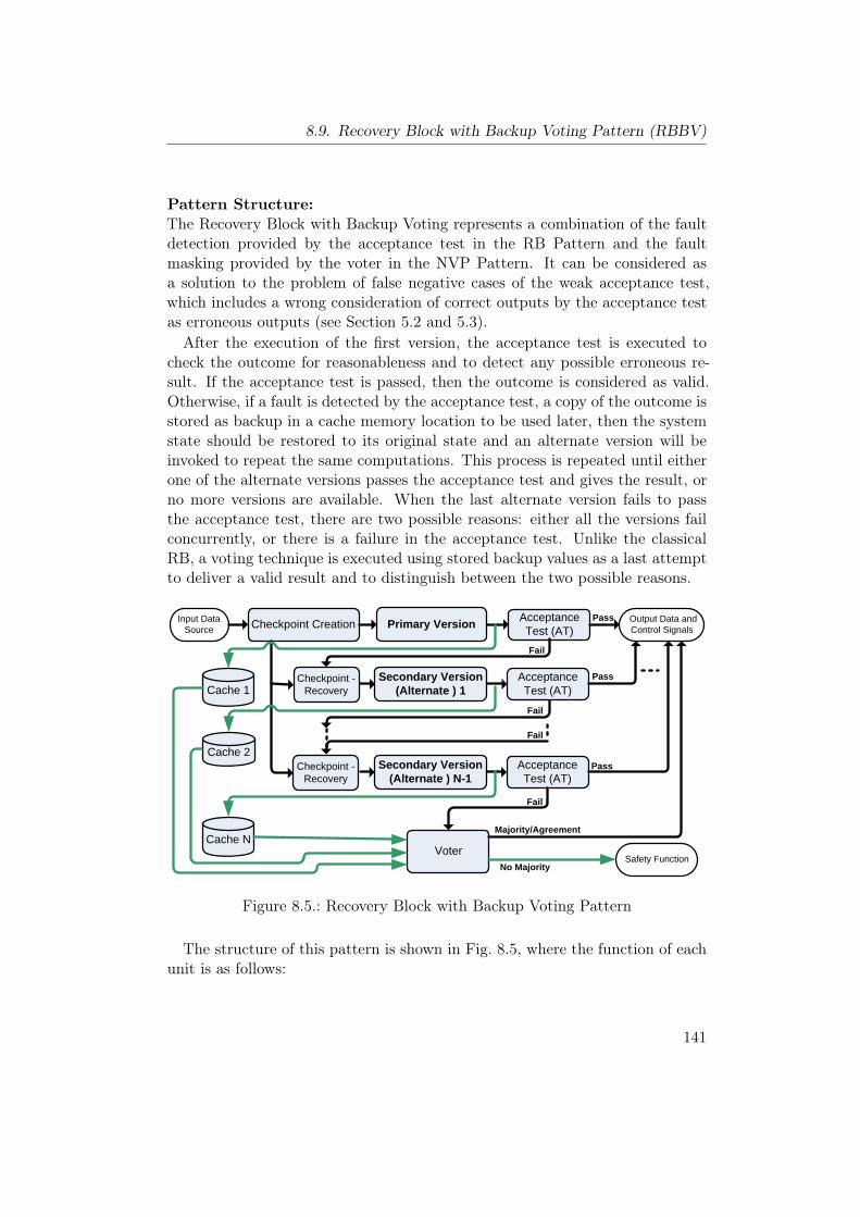
8.9. Recovery Block with Backup Voting Pattern (RBBV)
Pattern Structure:The Recovery Block with Backup Voting represents a combination of the faultdetection provided by the acceptance test in the RB Pattern and the faultmasking provided by the voter in the NVP Pattern. It can be considered asa solution to the problem of false negative cases of the weak acceptance test,which includes a wrong consideration of correct outputs by the acceptance testas erroneous outputs (see Section 5.2 and 5.3).After the execution of the first version, the acceptance test is executed to
check the outcome for reasonableness and to detect any possible erroneous re-sult. If the acceptance test is passed, then the outcome is considered as valid.Otherwise, if a fault is detected by the acceptance test, a copy of the outcome isstored as backup in a cache memory location to be used later, then the systemstate should be restored to its original state and an alternate version will beinvoked to repeat the same computations. This process is repeated until eitherone of the alternate versions passes the acceptance test and gives the result, orno more versions are available. When the last alternate version fails to passthe acceptance test, there are two possible reasons: either all the versions failconcurrently, or there is a failure in the acceptance test. Unlike the classicalRB, a voting technique is executed using stored backup values as a last attemptto deliver a valid result and to distinguish between the two possible reasons.
Checkpoint CreationInput Data Source
Acceptance Test (AT)
Output Data and Control SignalsPrimary Version
Checkpoint -Recovery
Acceptance Test (AT)
Secondary Version (Alternate ) 1
Checkpoint -Recovery
Acceptance Test (AT)
Secondary Version (Alternate ) N-1
Safety Function Voter
Cache 1
Cache 2
Cache N
Pass
Pass
Fail
Fail
Pass
Fail
Fail
No Majority
Majority/Agreement
Figure 8.5.: Recovery Block with Backup Voting Pattern
The structure of this pattern is shown in Fig. 8.5, where the function of eachunit is as follows:
141

8. Software Patterns
• Input Data Source: (see the general pattern in Section 6.7).
• Output Data and Control Signals: (see the general pattern in Section 6.7).
• Checkpoint Creation: In order to provide each alternate with the samedata and initial conditions, this component is used to create a checkpointthrough storing the system state before executing the primary version.
• Checkpoint-Recovery : This component is used to rollback the system to itsinitial state when the primary version or alternate versions fail to pass theacceptance test. This component is invoked before entering any alternateversion, where it takes the information about the stored checkpoint toswitch the system environment to the same point at which the primaryversion started computation.
• Primary and Secondary (Alternate) Versions: These functionally equiva-lent versions represent a result of independent implementations of therequired software by independent teams of programmers, based on thesame initial specification. The primary alternate is the one which is in-tended to be normally used to perform the desired operation. If a faultis detected in the primary version, then the alternate secondary versionsare executed in turn, until one alternate passes its acceptance test, or nomore secondary alternate versions are available.
In this pattern, a copy of the result of each failed version is stored in acache memory to be later used as input to a voting technique when allthe versions fail to pass the acceptance test.
• Acceptance Test (AT): It is the part of the software which is executed onthe exit from the alternate versions to confirm the correctness of the cal-culations based on the software specification. The acceptance test returnstrue or false, and it may have several components and may include checksfor runtime errors [97] and mechanisms for implicit error detection. Theacceptance test can be implemented in different variants that range fromsimple reasonableness checks to complex high-coverage validators, but thispattern is more suitable for the situations that include weak acceptancetests or it is difficult to develop an effective one. Nevertheless, the successof this pattern still depends on the performance and the quality of theacceptance test, and it should be carefully design and it should be simple,effective as much as possible.
• Cache Memory : This unit includes memory locations to store the resultsof the versions that fail the acceptance test. The size of these locationsdepend on the size of the output data and the number of alternate versions.
142
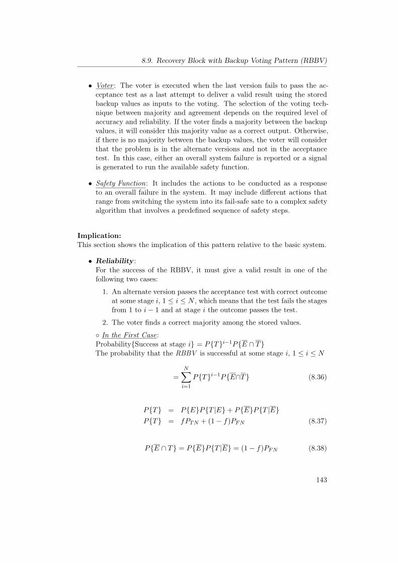
8.9. Recovery Block with Backup Voting Pattern (RBBV)
• Voter : The voter is executed when the last version fails to pass the ac-ceptance test as a last attempt to deliver a valid result using the storedbackup values as inputs to the voting. The selection of the voting tech-nique between majority and agreement depends on the required level ofaccuracy and reliability. If the voter finds a majority between the backupvalues, it will consider this majority value as a correct output. Otherwise,if there is no majority between the backup values, the voter will considerthat the problem is in the alternate versions and not in the acceptancetest. In this case, either an overall system failure is reported or a signalis generated to run the available safety function.
• Safety Function: It includes the actions to be conducted as a responseto an overall failure in the system. It may include different actions thatrange from switching the system into its fail-safe sate to a complex safetyalgorithm that involves a predefined sequence of safety steps.
Implication:This section shows the implication of this pattern relative to the basic system.
• Reliability :For the success of the RBBV, it must give a valid result in one of thefollowing two cases:
1. An alternate version passes the acceptance test with correct outcomeat some stage i, 1 ≤ i ≤ N , which means that the test fails the stagesfrom 1 to i− 1 and at stage i the outcome passes the test.
2. The voter finds a correct majority among the stored values.
◦ In the First Case:Probability{Success at stage i} = P{T}i−1P{E ∩ T}The probability that the RBBV is successful at some stage i, 1 ≤ i ≤ N
=N∑i=1
P{T}i−1P{E∩T} (8.36)
P{T} = P{E}P{T |E}+ P{E}P{T |E}P{T} = fPTN + (1− f)PFN (8.37)
P{E ∩ T} = P{E}P{T |E} = (1− f)PFN (8.38)
143
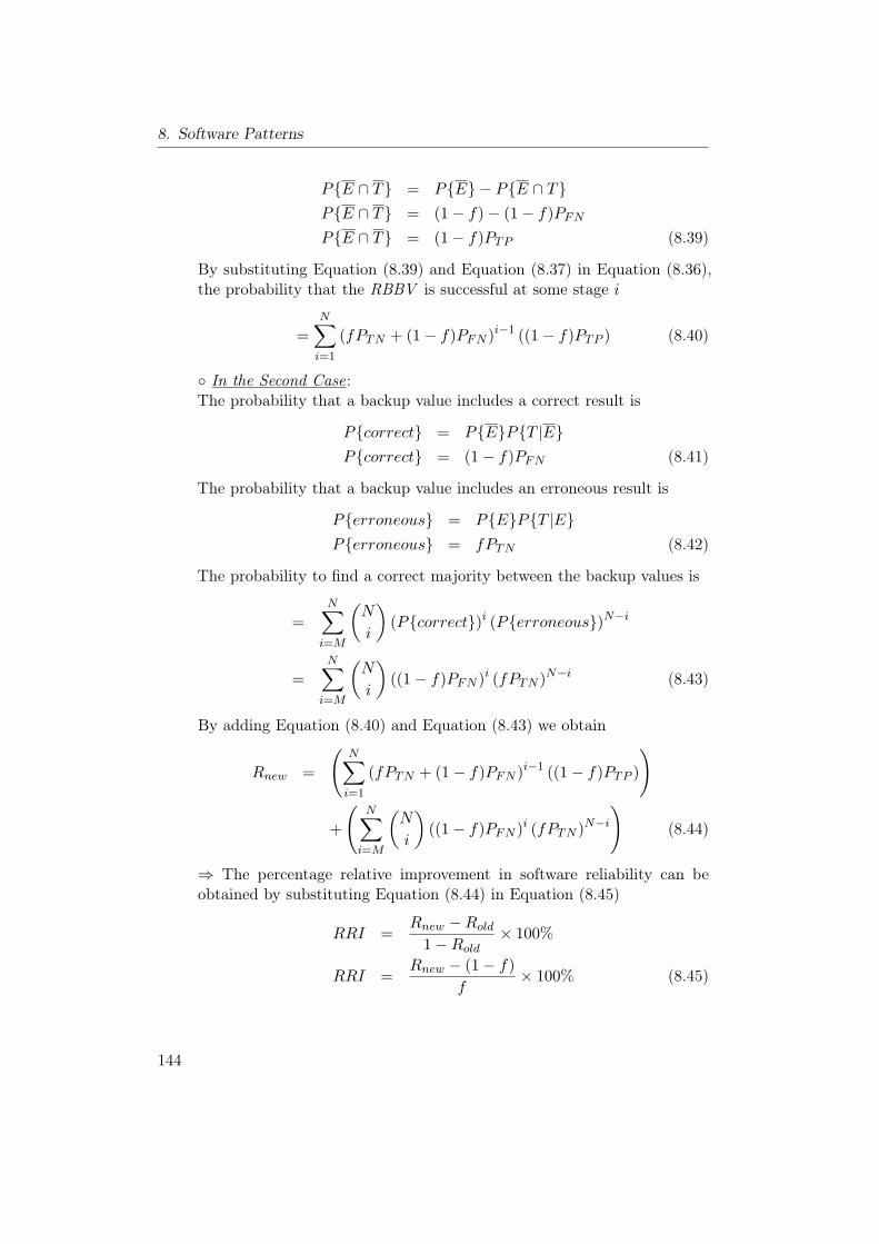
8. Software Patterns
P{E ∩ T} = P{E} − P{E ∩ T}P{E ∩ T} = (1− f)− (1− f)PFNP{E ∩ T} = (1− f)PTP (8.39)
By substituting Equation (8.39) and Equation (8.37) in Equation (8.36),the probability that the RBBV is successful at some stage i
=N∑i=1
(fPTN + (1− f)PFN )i−1 ((1− f)PTP ) (8.40)
◦ In the Second Case:The probability that a backup value includes a correct result is
P{correct} = P{E}P{T |E}P{correct} = (1− f)PFN (8.41)
The probability that a backup value includes an erroneous result is
P{erroneous} = P{E}P{T |E}P{erroneous} = fPTN (8.42)
The probability to find a correct majority between the backup values is
=N∑i=M
(N
i
)(P{correct})i (P{erroneous})N−i
=N∑i=M
(N
i
)((1− f)PFN )i (fPTN )N−i (8.43)
By adding Equation (8.40) and Equation (8.43) we obtain
Rnew =
(N∑i=1
(fPTN + (1− f)PFN )i−1 ((1− f)PTP )
)
+
(N∑i=M
(N
i
)((1− f)PFN )i (fPTN )N−i
)(8.44)
⇒ The percentage relative improvement in software reliability can beobtained by substituting Equation (8.44) in Equation (8.45)
RRI =Rnew −Rold
1−Rold× 100%
RRI =Rnew − (1− f)
f× 100% (8.45)
144
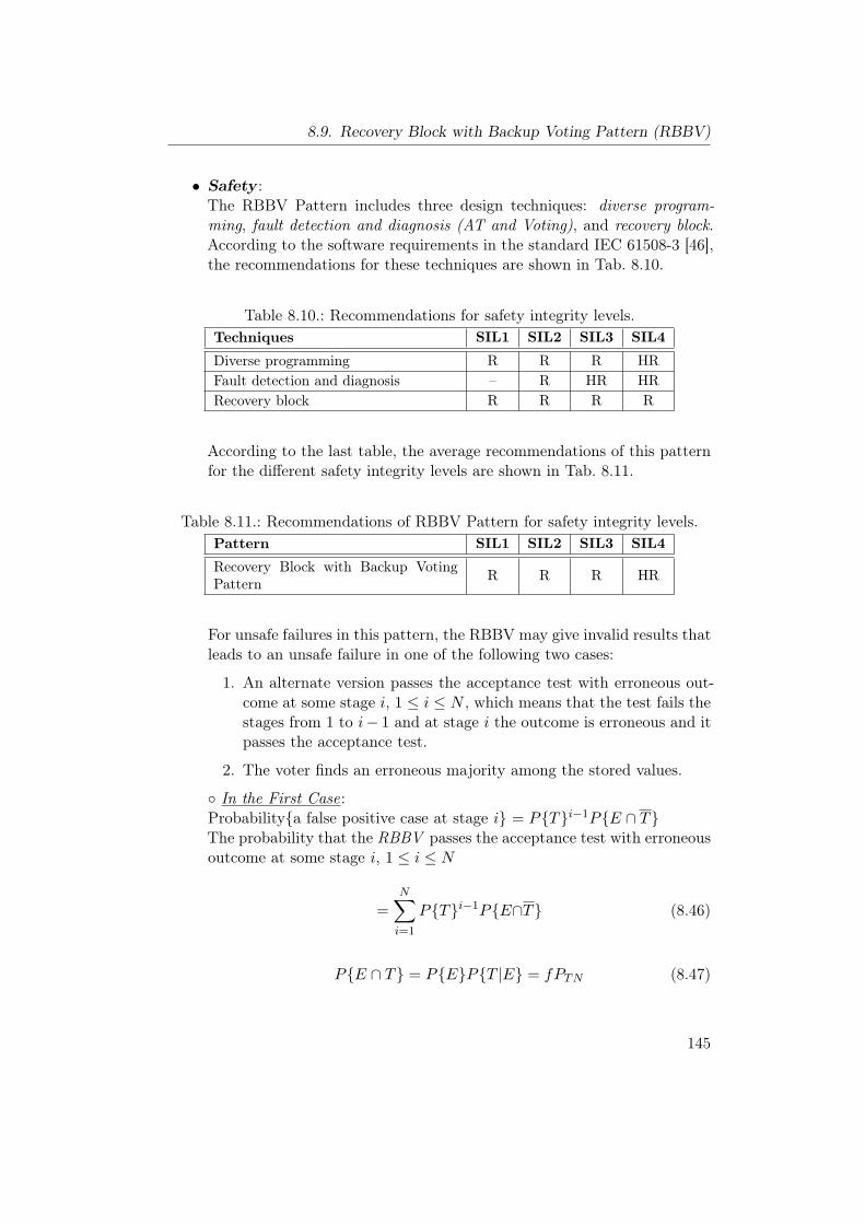
8.9. Recovery Block with Backup Voting Pattern (RBBV)
• Safety :The RBBV Pattern includes three design techniques: diverse program-ming, fault detection and diagnosis (AT and Voting), and recovery block.According to the software requirements in the standard IEC 61508-3 [46],the recommendations for these techniques are shown in Tab. 8.10.
Table 8.10.: Recommendations for safety integrity levels.Techniques SIL1 SIL2 SIL3 SIL4
Diverse programming R R R HRFault detection and diagnosis – R HR HRRecovery block R R R R
According to the last table, the average recommendations of this patternfor the different safety integrity levels are shown in Tab. 8.11.
Table 8.11.: Recommendations of RBBV Pattern for safety integrity levels.Pattern SIL1 SIL2 SIL3 SIL4
Recovery Block with Backup VotingPattern R R R HR
For unsafe failures in this pattern, the RBBV may give invalid results thatleads to an unsafe failure in one of the following two cases:
1. An alternate version passes the acceptance test with erroneous out-come at some stage i, 1 ≤ i ≤ N , which means that the test fails thestages from 1 to i− 1 and at stage i the outcome is erroneous and itpasses the acceptance test.
2. The voter finds an erroneous majority among the stored values.
◦ In the First Case:Probability{a false positive case at stage i} = P{T}i−1P{E ∩ T}The probability that the RBBV passes the acceptance test with erroneousoutcome at some stage i, 1 ≤ i ≤ N
=N∑i=1
P{T}i−1P{E∩T} (8.46)
P{E ∩ T} = P{E}P{T |E} = fPTN (8.47)
145
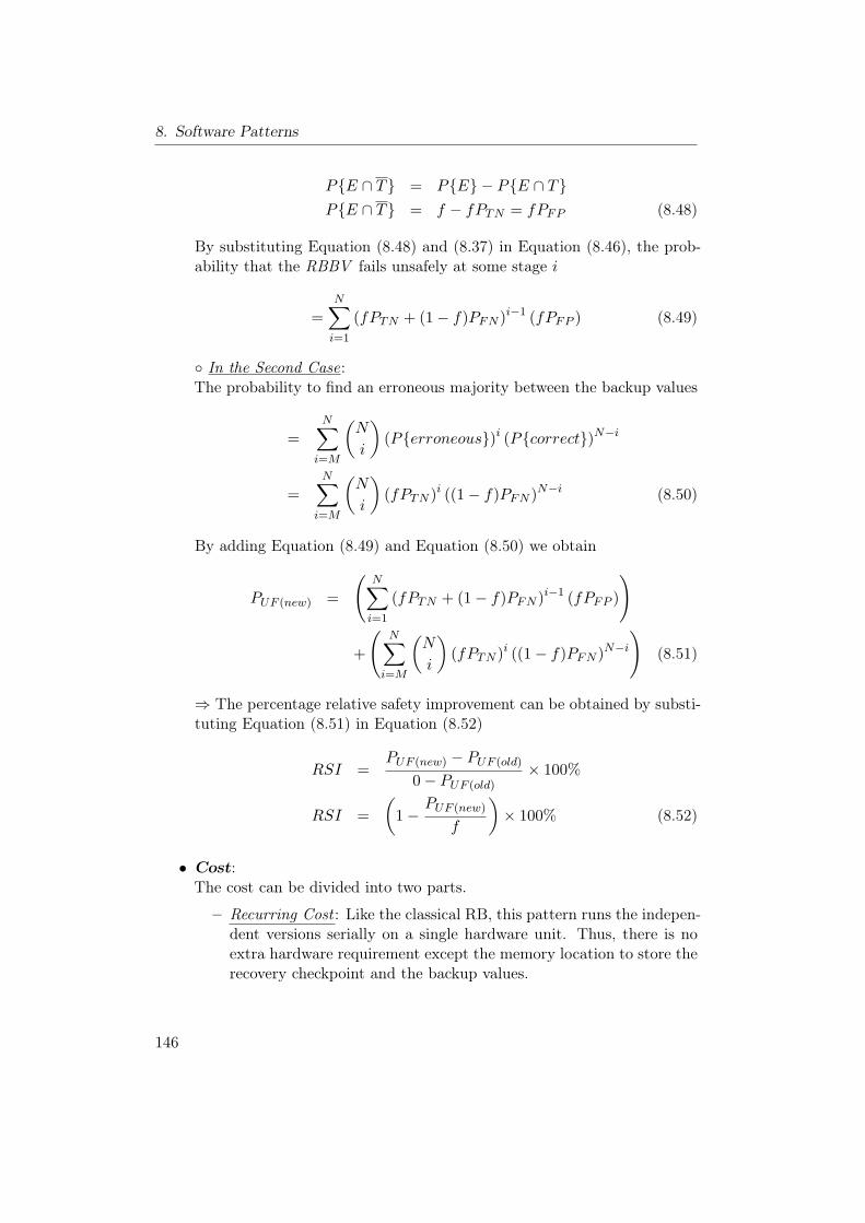
8. Software Patterns
P{E ∩ T} = P{E} − P{E ∩ T}P{E ∩ T} = f − fPTN = fPFP (8.48)
By substituting Equation (8.48) and (8.37) in Equation (8.46), the prob-ability that the RBBV fails unsafely at some stage i
=N∑i=1
(fPTN + (1− f)PFN )i−1 (fPFP ) (8.49)
◦ In the Second Case:The probability to find an erroneous majority between the backup values
=N∑i=M
(N
i
)(P{erroneous})i (P{correct})N−i
=N∑i=M
(N
i
)(fPTN )i ((1− f)PFN )N−i (8.50)
By adding Equation (8.49) and Equation (8.50) we obtain
PUF (new) =
(N∑i=1
(fPTN + (1− f)PFN )i−1 (fPFP )
)
+
(N∑i=M
(N
i
)(fPTN )i ((1− f)PFN )N−i
)(8.51)
⇒ The percentage relative safety improvement can be obtained by substi-tuting Equation (8.51) in Equation (8.52)
RSI =PUF (new) − PUF (old)
0− PUF (old)× 100%
RSI =(
1−PUF (new)
f
)× 100% (8.52)
• Cost:The cost can be divided into two parts.
– Recurring Cost : Like the classical RB, this pattern runs the indepen-dent versions serially on a single hardware unit. Thus, there is noextra hardware requirement except the memory location to store therecovery checkpoint and the backup values.
146
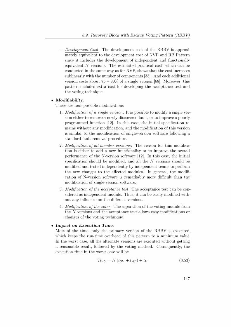
8.9. Recovery Block with Backup Voting Pattern (RBBV)
– Development Cost : The development cost of the RBBV is approxi-mately equivalent to the development cost of NVP and RB Patternsince it includes the development of independent and functionallyequivalent N versions. The estimated practical cost, which can beconducted in the same way as for NVP, shows that the cost increasessublinearly with the number of components [33]. And each additionalversion costs about 75− 80% of a single version [68]. Moreover, thispattern includes extra cost for developing the acceptance test andthe voting technique.
• Modifiability :There are four possible modifications
1. Modification of a single version: It is possible to modify a single ver-sion either to remove a newly discovered fault, or to improve a poorlyprogrammed function [12]. In this case, the initial specification re-mains without any modification, and the modification of this versionis similar to the modification of single-version software following astandard fault removal procedure.
2. Modification of all member versions: The reason for this modifica-tion is either to add a new functionality or to improve the overallperformance of the N-version software [12]. In this case, the initialspecification should be modified, and all the N versions should bemodified and tested independently by independent teams to performthe new changes to the affected modules. In general, the modifi-cation of N-version software is remarkably more difficult than themodification of single-version software.
3. Modification of the acceptance test : The acceptance test can be con-sidered as independent module. Thus, it can be easily modified with-out any influence on the different versions.
4. Modification of the voter : The separation of the voting module fromthe N versions and the acceptance test allows easy modifications orchanges of the voting technique.
• Impact on Execution Time:Most of the time, only the primary version of the RBBV is executed,which keeps the run-time overhead of this pattern to a minimum value.In the worst case, all the alternate versions are executed without gettinga reasonable result, followed by the voting method. Consequently, theexecution time in the worst case will be
TWC = N (tSV + tAT ) + tV (8.53)
147
8. Software Patterns
Where:− tSV : the execution time of a single version.− tAT : the execution time of the acceptance test.− tV : the execution time of the voter.− tWC : the worst case execution time of the RBBV methods.
Due to the weak acceptance test, it is more likely that more than oneversion are executed before offering a valid result, which increases the av-erage execution time. Consequently, the execution time overhead of theRBBV in worst and average cases can be considered as the main disad-vantage that makes this method unsuitable for real-time safety criticalsystem with strict timing constraints.
Implementation:
1. While the RBBV can handle false negative cases, its ability to detect falsepositive, true positive, and true negative cases still depends on the qualityof the acceptance test. Thus, the acceptance test should be carefullydesigned to allow high fault coverage.
2. The independent development of the required N versions and the levelof diversity in these versions to avoid the common failures. In order toincrease the level of diversity and the independence of the developed ver-sions, the implementation issues presented in Section 8.2 should be takeninto consideration as long as possible during the development process.
3. There are several voting techniques that can be used in this pattern toimplement the voter component (see Section 8.4). The selection of thesuitable technique depends on the data type, deviation in the outputs ofthe versions, type of agreement [63], output space cardinality size, func-tionality of the voter [75], reliability of different versions, and many otherfactors.
Consequences and Side Effects:Similar to the classical RB, the main drawbacks of this pattern are the complex-ity of developing independent N versions in addition to the high developmentcost and the high dependency on the initial specification which may propagatefaults to all versions.
Related Patterns:To test the software versions for timeout condition and to provide sequencemonitoring, the RBBV Pattern can be combined with the Watchdog Pattern.
148
9. Combination of Hardware andSoftware Patterns
9.1. Protected Single Channel Pattern (PSC)
Other Names:–
Type:Combination of Hardware and Software Pattern.
Abstract:The Protected Single Channel Pattern [37] is a light weight pattern that is usedto enhance the safety and reliability through the addition of checks and monitor-ing at different points in the channel. It is normally used to deal with transientfaults.
Context:Developing an embedded system with limited safety and reliability requirementsin a situation where some level of redundancy is possible.
Problem:How to deal with the transient faults to provide some level of safety and relia-bility to the embedded system in an inexpensive manner.
Pattern Structure:The pattern structure is shown in Fig. 9.1. It contains two possible monitoringunits: one for input data validation and one for actuation monitoring. Thus,there are two versions of this pattern; (open loop) when the input data valida-tion unit is only used, and (closed loop) when the two units are used [37].
The function of each unit is as follows:
• Actuation Channel : (see the general pattern in Section 6.7).
• Input Sensor(s): (see the general pattern in Section 6.7).
149
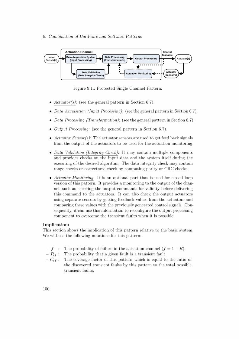
9. Combination of Hardware and Software Patterns
Input Sensor(s)
Data Acquisition System (Input Processing)
Data Processing (Transformations) Output Processing Actuator(s)
Data Validation (Data Integrity Check)
Actuator Sensor(s) Actuation Monitoring
Control Signal(s)
Actuation Channel
Figure 9.1.: Protected Single Channel Pattern.
• Actuator(s): (see the general pattern in Section 6.7).
• Data Acquisition (Input Processing): (see the general pattern in Section 6.7).
• Data Processing (Transformation): (see the general pattern in Section 6.7).
• Output Processing : (see the general pattern in Section 6.7).
• Actuator Sensor(s): The actuator sensors are used to get feed back signalsfrom the output of the actuators to be used for the actuation monitoring.
• Data Validation (Integrity Check): It may contain multiple componentsand provides checks on the input data and the system itself during theexecuting of the desired algorithm. The data integrity check may containrange checks or correctness check by computing parity or CRC checks.
• Actuator Monitoring : It is an optional part that is used for closed loopversion of this pattern. It provides a monitoring to the output of the chan-nel, such as checking the output commands for validity before deliveringthis command to the actuators. It can also check the output actuatorsusing separate sensors by getting feedback values from the actuators andcomparing these values with the previously generated control signals. Con-sequently, it can use this information to reconfigure the output processingcomponent to overcome the transient faults when it is possible.
Implication:This section shows the implication of this pattern relative to the basic system.We will use the following notations for this pattern:
− f : The probability of failure in the actuation channel (f = 1−R).− Ptf : The probability that a given fault is a transient fault.− Ctf : The coverage factor of this pattern which is equal to the ratio of
the discovered transient faults by this pattern to the total possibletransient faults.
150
9.1. Protected Single Channel Pattern (PSC)
• Reliability :The remaining failures after using this pattern include the other types andthe undiscovered transient failures, with probability = (1− CtfPtf ) f .
Rnew = 1− (1− CtfPtf ) f (9.1)
⇒ The percentage relative improvement in reliability is
RRI =Rnew −Rold
1−Rold× 100%
RRI =1− (1− CtfPtf ) f − (1− f)
1− (1− f)× 100%
RRI = CtfPtf × 100% (9.2)
• Safety :This pattern includes a single technique which can be classified as failuredetection by online monitoring. According to the hardware requirementsin the standard IEC 61508-2 [46], the recommendations for this techniqueare shown in Tab. 9.1.
Table 9.1.: Recommendations of PSC Pattern for safety integrity levels.Techniques SIL1 SIL2 SIL3 SIL4
Protected Single Channel Pattern (fail-ure detection by online monitoring) HR HR HR HR
The protected single channel pattern can only cover the transient faultsto provide some level of safety. But it can not continue to operate safelyin the presence of persistent faults. Therefore, it is not applicable to workalone for any situation that requires any special safety integrity. It shouldbe integrated with another safety technique in the presence of immediatefail-safe state to be used for light safety-critical applications.
To compute RSI:
PUF (old) = 1−RAC = 1−R = f (9.3)
The probability of unsafe failure after using this pattern:
PUF (new) = (1− CtfPtf ) f (9.4)
151
9. Combination of Hardware and Software Patterns
⇒ The percentage relative safety improvement is
RSI =PUF (new) − PUF (old)
0− PUF (old)× 100%
RSI =(1− CtfPtf ) f − f
0− f× 100%
RSI = CtfPtf × 100% (9.5)
Equation (9.5) and Equation (9.2) show that the relative safety improve-ment is equal to the relative reliability improvement.
• Cost:The extra cost in this pattern depends on the method of implementation,and can be classified into two parts:
– Recurring Cost : It includes the cost of extra sensors, data validationunit if it is implemented as hardware component, and the cost ofmemory locations for data redundancy such as(CRC).
– Development Cost : The cost for developing a software procedure toperform some part of data validation and checking.
In general, the cost for this pattern is small comparing to the other pat-terns that include high level of redundancy.
• Modifiability :It is possible to modify this pattern by adding extra module for furtherdata validation or actuator monitoring, but this involves the extra hard-ware units which will increase the recurring cost. On the other hand, thevalidation and checking algorithm must be modified to take into consider-ation the new components and the new checking algorithms.
• Impact on Execution Time:The influence of this pattern on the executing time depends on the imple-mentation:
– If the validation checks are performed by hardware, then the extracomponents are working in parallel with the basic channel which doesnot affect the basic system in the normal execution.
– In the case of software implementation, the increase in the executiontime depends on the required time to execute the extra algorithmcomparing to the original software.
152
9.1. Protected Single Channel Pattern (PSC)
Implementation:
• In this pattern, there are two versions to be implemented: either (openloop) with only data integrity checking unit, or (close loop) that includesadditional actuation monitoring unit.
• The designer should determine the input data to monitor and he musthave a semantic knowledge about the data, which can be used for out ofrange value checking.
• There are two options to provide the data checking: either by software orby hardware.
• When there is no time constraint in the application, the designer shouldtry to use software checking, to reduce the recurring cost, especially inproducts with large quantities.
• For data integrity, redundant storage unit can be used. For example, toprovide checksum for stored data that can be computed at runtime andcan be compared with the stored value in the storage unit.
• It is good choice to store the redundant data in inverted format to detectstuck-at RAM fault.
• When it is possible to have an immediate fail-safe state, it should beused in the design to increase the safety level. The existence of a fail-safestate gives the data integrity and the actuator monitoring components thecapability to switch the system into the fail-safe state in the presence ofpersistent fault.
Consequences and Side Effects:The main drawback of this pattern is that it is not appropriate for dealing withpersistent faults, since it can not continue to operate safely, and sometime leadsto the loss of the entire system.
Related Patterns:To give a high level of integrity, additional patterns can be used beside thispattern to deal with the random and systematic persistent faults. Such as ho-mogeneous duplex, heterogeneous redundancy, and triple modular redundancypattern.
153
9. Combination of Hardware and Software Patterns
9.2. 3-Level Safety Monitoring Pattern (3-LSM)
Other Names:E-GAS.
Type:Combination of Hardware and Software Pattern.
Abstract:The 3-Level Safety Monitoring Pattern is considered as a combination of theMonitor-Actuator Pattern and the Watchdog Pattern to be suitable for the ap-plications that require a continuous safety monitoring and include a fail-safestate without high hardware redundancy. It consists of a single hardware chan-nel that includes 3 levels: actuation (function), monitoring, and control level.The function level executes the subprogram for carrying out the intended func-tionality, while the monitoring level monitors the first level, and the control levelcontrols the monitoring level and the entire hardware channel. Furthermore, awatchdog, which communicates via periodic messages with the control level, isused to reset the system into its fail-safe state in the case of failure.
Context:Developing an embedded system with a given fail-safe state or a corrective ac-tion, and without hardware redundancy.
Problem:How to improve the safety of an embedded system at low reasonable cost, inthe presence of failure in a system with a fail-safe state. Furthermore, how tocontinue providing the required safety level and to ensure that the system doesno injure or harm, when there is any deviation in the output of the actuatorsfrom the commanded set point.
Pattern Structure:The 3-Level Safety Monitoring was proposed by Robert Bosch GmbH to beused in the E-Gas unit as a method for management and controlling the drivepower of a motor vehicle [17]. It consists of a single hardware channel to performthree computing elements: Actuation, monitoring and control element. Thispattern provides higher safety monitoring than the classical watchdog patternsince it includes a functional monitoring element besides the sequence controlprovided in the classical watchdog pattern. Nevertheless, the fault coverage inthis patter is less than in the Monitor-Actuator and the Sanity Check Patternsince it includes a single hardware channel instead of two.
154
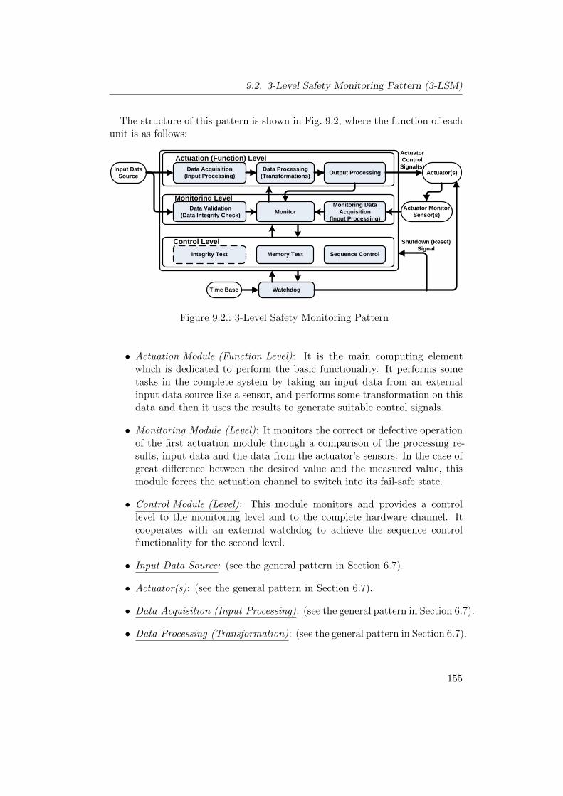
9.2. 3-Level Safety Monitoring Pattern (3-LSM)
The structure of this pattern is shown in Fig. 9.2, where the function of eachunit is as follows:
Input Data Source Actuator(s)
Actuator Monitor Sensor(s)
ActuatorControl
Signal(s)
WatchdogTime Base
Shutdown (Reset)Signal
Data Acquisition(Input Processing)
Data Processing (Transformations) Output Processing
Actuation (Function) Level
Data Validation (Data Integrity Check) Monitor
Monitoring Data Acquisition
(Input Processing)
Monitoring Level
Integrity Test Memory Test Sequence Control
Control Level
Figure 9.2.: 3-Level Safety Monitoring Pattern
• Actuation Module (Function Level): It is the main computing elementwhich is dedicated to perform the basic functionality. It performs sometasks in the complete system by taking an input data from an externalinput data source like a sensor, and performs some transformation on thisdata and then it uses the results to generate suitable control signals.
• Monitoring Module (Level): It monitors the correct or defective operationof the first actuation module through a comparison of the processing re-sults, input data and the data from the actuator’s sensors. In the case ofgreat difference between the desired value and the measured value, thismodule forces the actuation channel to switch into its fail-safe state.
• Control Module (Level): This module monitors and provides a controllevel to the monitoring level and to the complete hardware channel. Itcooperates with an external watchdog to achieve the sequence controlfunctionality for the second level.
• Input Data Source: (see the general pattern in Section 6.7).
• Actuator(s): (see the general pattern in Section 6.7).
• Data Acquisition (Input Processing): (see the general pattern in Section 6.7).
• Data Processing (Transformation): (see the general pattern in Section 6.7).
155
9. Combination of Hardware and Software Patterns
• Output Processing : (see the general pattern in Section 6.7).
• Data Validation (Data Integrity Check): It provides a check on the inputdata during the executing of the desired algorithm to ensure that theinput data is valid and in the safe boundaries.
• Actuator Monitor Sensor(s): It represents a source of information to themonitoring module, where it is used to get feedback signals from theoutput of the actuators to provide a monitoring to the actuation level.
• Monitoring Data Acquisition: It collects the raw data from the actuatorsensors and may convert the data to another form, and then it transfersthe data to the monitor component.
• Monitor : The monitor takes information about the status of the actuatorand compares it with the provided input commands and with the actuatorcontrol signal computed in the first level. The result of comparison is usedto ensure that the actuation output is approximately correct and withina given range. If the result of the comparison shows that the output ofactuation channel is totally incorrect and may affect the system safety,the monitor will generate a correction command or shutdown signal toswitch the system into its fail-safe state.
• Watchdog : It is used to provide a sequence control to the monitoring leveland to the entire actuation channel. The functionality of the watchdogvaries from: a simple liveness messages (strokes) received from the mainhardware of the actuation channel in a predefined timeframe, to a complexquery messages between the watchdog and the sequence control module.In the last case, the watchdog transmits a query determined by a randomnumber generator to the sequence control. The sequence control invokessome tests and constructs the result signal which is sent back to watchdog.The watchdog compares the received result with the original transmittedquery. If the watchdog detects a deviation, then it considers this situationas a fault in the hardware channel, and then it issues a shutdown signalto switch the main channel and the actuators to the fail-safe state.
• Sequence Control : The sequence control module receives the query trans-mitted from the watchdog, and then evaluates this message and deter-mines the subprograms or tests that should be executed to reply the query.When all the selected subprograms and tests have been executed, then theresult message is constructed and transmitted back to the watchdog.
• Memory Test : This module includes read/write RAM test and read ROMtest to insure the correctness and integrity of the internal memory.
156
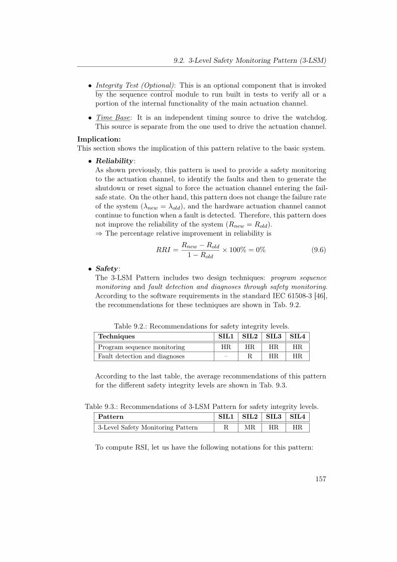
9.2. 3-Level Safety Monitoring Pattern (3-LSM)
• Integrity Test (Optional): This is an optional component that is invokedby the sequence control module to run built in tests to verify all or aportion of the internal functionality of the main actuation channel.
• Time Base: It is an independent timing source to drive the watchdog.This source is separate from the one used to drive the actuation channel.
Implication:This section shows the implication of this pattern relative to the basic system.
• Reliability :As shown previously, this pattern is used to provide a safety monitoringto the actuation channel, to identify the faults and then to generate theshutdown or reset signal to force the actuation channel entering the fail-safe state. On the other hand, this pattern does not change the failure rateof the system (λnew = λold), and the hardware actuation channel cannotcontinue to function when a fault is detected. Therefore, this pattern doesnot improve the reliability of the system (Rnew = Rold).⇒ The percentage relative improvement in reliability is
RRI =Rnew −Rold
1−Rold× 100% = 0% (9.6)
• Safety :The 3-LSM Pattern includes two design techniques: program sequencemonitoring and fault detection and diagnoses through safety monitoring.According to the software requirements in the standard IEC 61508-3 [46],the recommendations for these techniques are shown in Tab. 9.2.
Table 9.2.: Recommendations for safety integrity levels.Techniques SIL1 SIL2 SIL3 SIL4
Program sequence monitoring HR HR HR HRFault detection and diagnoses – R HR HR
According to the last table, the average recommendations of this patternfor the different safety integrity levels are shown in Tab. 9.3.
Table 9.3.: Recommendations of 3-LSM Pattern for safety integrity levels.Pattern SIL1 SIL2 SIL3 SIL4
3-Level Safety Monitoring Pattern R MR HR HR
To compute RSI, let us have the following notations for this pattern:
157
9. Combination of Hardware and Software Patterns
− RAC : The reliability of the actuation channel.− RWD : The reliability of the watchdog component.− CML : The coverage factor of the monitoring level which is equal
to the probability that an unsafe failure in the actuationmodule is detected by the monitoring module.
− CWD : The coverage factor of the watchdog and control level whichis equal to the probability that undetected failure, either inmonitoring module or in the hardware actuation channel, isdetected by the watchdog and the control level.
− EML : The event that a failure is detected by the monitoring level.− EWD : The event that a failure is detected by the watchdog and
control level.
The probability of failure in the actuation channel is equal to the failurein a simple channel
PUF (old) = 1−RAC = 1−R (9.7)
The failures in the actuation channel can be divided into two groups:
1. Safe failures detected by the monitoring module or the control mod-ule with the watchdog.
2. Unsafe failures those are undetected neither by the monitoring mod-ule nor by the control module with the watchdog.
∗ The probability that a failure is detected by the monitoring module
= (1−RAC)CML (9.8)
∗ The probability that a failure is not detected by the monitoring module
= (1−RAC) (1− CML) (9.9)
∗ The probability that a failure is not detected by the monitoring leveland then detected by the watchdog
= (1−RAC) (1− CML)RWDCWD (9.10)
∗ The probability that a failure is not detected neither by the monitoringlevel nor by the watchdog
= (1−RAC) (1− CML) (1−RWDCWD) (9.11)
158
9.2. 3-Level Safety Monitoring Pattern (3-LSM)
Therefore, the probability of unsafe failure in this pattern is
PUF (new) = (1−R) (1− CML) (1−RWDCWD) (9.12)
If we assume that the watchdog was carefully designed (RWD ≈ 1) then
PUF (new) ≈ (1−R) (1− CML) (1− CWD) (9.13)
⇒ The percentage relative safety improvement is
RSI =PUF (new) − PUF (old)
0− PUF (old)× 100%
RSI =(1−R) (1− CML) (1− CWD)− (1−R)
0− (1−R)× 100%
RSI = (CML + CWD − CMLCWD)× 100% (9.14)
If we define the coverage factor for the 3-Level Safety Monitoring Pattern(C3LSM ) to be the probability that a failure is detected either by the mon-itoring level or by the control level and the watchdog, then this coveragefactor can be calculated as follows:
C3LSM = P{EML ∪ EWD}C3LSM = P{EML}+ P{EWD} − P{EML}P{EWD}C3LSM = (CML + CWD − CMLCWD) (9.15)
⇒ The percentage relative safety improvement is
RSI = C3LSM × 100% (9.16)
It is clear from Equation (9.16) that the safety improvement depends onthe coverage factor of this pattern, which in turn depends on the cov-erage factor of the monitoring module and the coverage factor of thewatchdog. The monitoring module in this pattern is not able to detecthardware failure in the main hardware channel since it is executed bythe same hardware channel as the functional level. Therefore, the cover-age factor and the safety improvement in this pattern is less than in theMonitor-Actuator and the Sanity-Check Pattern. Nevertheless, the safetyimprovement is greater than the classical watchdog pattern.
• Cost:The low-cost of this pattern can be classified into two parts:
– Recurring Cost : It includes the cost of the watchdog component,independent timing source and extra sensors.
159
9. Combination of Hardware and Software Patterns
– Development Cost : It include the cost for developing the monitoringmodule, control level and periodic tests.
• Modifiability :The modification of the actuation level to add extra features is consideredto be an easy step that involves the following:
– The modification of the monitoring module to provide a monitoringto the new features, and this will include additional new sensors,modification of the monitoring data acquisition and modification ofthe monitor in order to take the new features into consideration.
– The modification of the control module to include extra tests.
• Impact on Execution Time:As shown in the pattern structure, the three levels are executed on thesame hardware channel; thus, the total execution time will be affectedby the time to execute the actuation level, the monitoring module, andthe periodic tests in the control level. Therefore, the additional executiontime will depend on the complexity of the monitoring and control level.
Implementation:
• In order to decrease the recurring cost, two different types of sensors can beused for implementation: high sensitivity sensors for the basic actuationlevel, and low-cost and low-sensitivity sensors for the monitoring level.
• If low-sensitive sensors are used for the monitoring level, then a simplealgorithm should be used to perform the required broad range comparison.
• Based on the level of complexity, some factors like: time lag, measurementand computational accuracy, and data formatting errors, might affect thecomparison algorithm in the monitoring level. Therefore, these factorsshould be taken into consideration in the implementation of this pattern.
Consequences and Side Effects:The main drawback for this pattern is that it includes a single hardware chan-nel; thus, it can not be used to tolerate hardware failures in applications withhigh reliability and availability requirements.
Related Patterns:The Monitor-Actuator Pattern is the most related pattern to the 3-Level SafetyMonitoring Pattern, since it represent a special implementation when the moni-toring and control level are carried out in a separate hardware channel with theaddition of a watchdog.
160
10. Conclusion
This chapter summarizes the contributions of this thesis and draws some con-clusions about this research. Finally, it outlines some possible directions forfuture work.
10.1. Summary
In this thesis, we developed an approach for the adoption of the design pat-tern concept for safety-critical embedded systems design. A catalog of designpatterns was constructed to provide a set of well-known, structured, and docu-mented design solutions for safety-critical embedded systems.The representation of design solutions as design patterns serves two advan-
tages. Firstly, it can simplify communication between practitioners by providinga good way for documentation of proven design techniques; and secondly, it sup-port and help designers and system architects choose a suitable solution for arecurring design problem among available collection of successful solutions.Unlike traditional computer system, safety-critical embedded systems have
special functional and non-functional requirements that should be met by theavailable design methods. Consequently, these requirements should be includedwhen the design solutions are presented as design patterns.
To overcome the lack of consideration of non-functional side effects and poten-tial consequences in the available pattern representations, Chapter 3 presentedan effective pattern representation template that focuses on the implication andside effects on the non functional requirements. Comparing to the traditionalpattern representations, this template includes the essential elements in addi-tion to a section for the implications on non-function requirements that includesafety, reliability, modifiability, cost and execution time.Among the different requirements for safety-critical systems, this thesis fo-
cused on safety and reliability as they have direct effects on the users and theenvironment. These two requirements are used as major factors in the differen-tiation between available patterns. Chapter 4 described reliability and safetyassessment method that can be employed to facilitate the comparison possessof design patterns for their suitability for a specific design problem.The reliability assessment method includes a reliability metric which describes
the percentage reliability improvement relatively to a basic system. This rela-
161
10. Conclusion
tive computation overcomes the abstraction problem of design patterns andgives an indication about the possible improvement that can be achieved whenusing the pattern under consideration. Similarly, the safety assessment methodincludes a safety metric based on the computation of the relative safety im-provement based on the possible reduction in the probability of unsafe failures.Moreover, the safety assessment includes a system of safety recommendationsderived from the safety integrity levels, presented in the IEC 61508 standard,and the recommendations for these levels. The combination of these two partsin the safety assessment reflects the importance of the addressed design patternand the possible severity of the target applications.The question that arises is how to apply these abstract metrics. In this thesis,
we presented two approaches to use the developed safety and reliability metricsin the assessment process of design patterns:
• Through the employment of a mathematical modelling, as done in ourcatalog of patterns.
• By using simulation techniques.
Chapter 5 clarified how to carry out a simulation method to demonstratethe presented assessment methods. It described a case study that includes aMonte Carlo based simulation to assess four software design patterns. Further-more, it illustrated how to conduct a comparison between patterns, and how toinvestigate the main parameters that affects their reliability and safety.Chapter 6 described the architecture of the software version of the constructed
catalog of design patterns. It detailed the main modules and the data modelused to implement this catalog. The main features provided in this catalog canbe summarized in: easy to use, well-documented patterns, interactive navigationand browsing, simulation of software patterns, and a decision support for users.The selection of a suitable design pattern for a given design problem is consid-
ered to be a tedious and unstructured process. Therefore, the decision supportdeveloped in our catalog aims to help users to overcome decision making prob-lems. The developed approach involved the following:
• Provision of a set of possible pattern combinations as a set of solutions.
• Categorizing these solutions into groups based on the problems that canbe solved.
• Construction of decision trees that associate the applicable solutions foreach design problem with the requirements for these solutions.
The decision support was developed in our tool as a search wizard which exploitsthe constructed decision trees to assist users in the selection process.
162
10.2. Future Work
The last part of this thesis, Chapter 7, 8 and 9, presented the design patternsthat form our catalog. The collected patterns included fifteen patterns whichare divided into three groups based on the type of patterns: hardware, software,and a combination of hardware and software patterns. We think that thisdivision is sufficient for our catalog since it classifies all patterns that share thesame design concepts and solve related problems in a same category.Summarizing, we believe that applying the concept of design patterns to the
field of safety-critical embedded systems is very promising in the use of provensolutions. The integration of non-functional requirements in the proposed repre-sentation aims to give an indication about the possible impacts and side effectsof a considered design pattern and to help in the general assessment of designpatterns.While the proposed assessment method covers only safety and reliability,
there are many other factors that should be taken into consideration to achievea comprehensive comparison. These factors include, among others: costs, timeoverhead and maintainability.On the other hand, the main criticisms of our approach can be derived from
the general criticism of the concept of design patterns. It can be claimed thatthe non-functional requirements are highly dependant on the implementation,and the abstract nature of design patterns does not give complete informationabout the final system.While we do not argue that design patterns give partial information, we think
that the introduction of this abstract information at the early stages of a designcan be of great benefit to the design process. Moreover, we have to keep inmind that the use of the recommendations that are presented in our patternsand in the safety assessment method does not guarantee the satisfaction of therequired safety integrity in the final design. In contrary, the standard shouldbe followed throughout the entire life-cycle in order to get a certificate for aspecific safety integrity level.
10.2. Future Work
The research presented in this thesis introduces some possible directions forfuture work.
• The presented catalog only includes fifteen design patterns that representcommon design solutions. Thus, this catalog is applicable to be extendedto include more patterns. Other design techniques that address safety-critical embedded systems can be represented as pattern and later beincluded in this catalog.
163
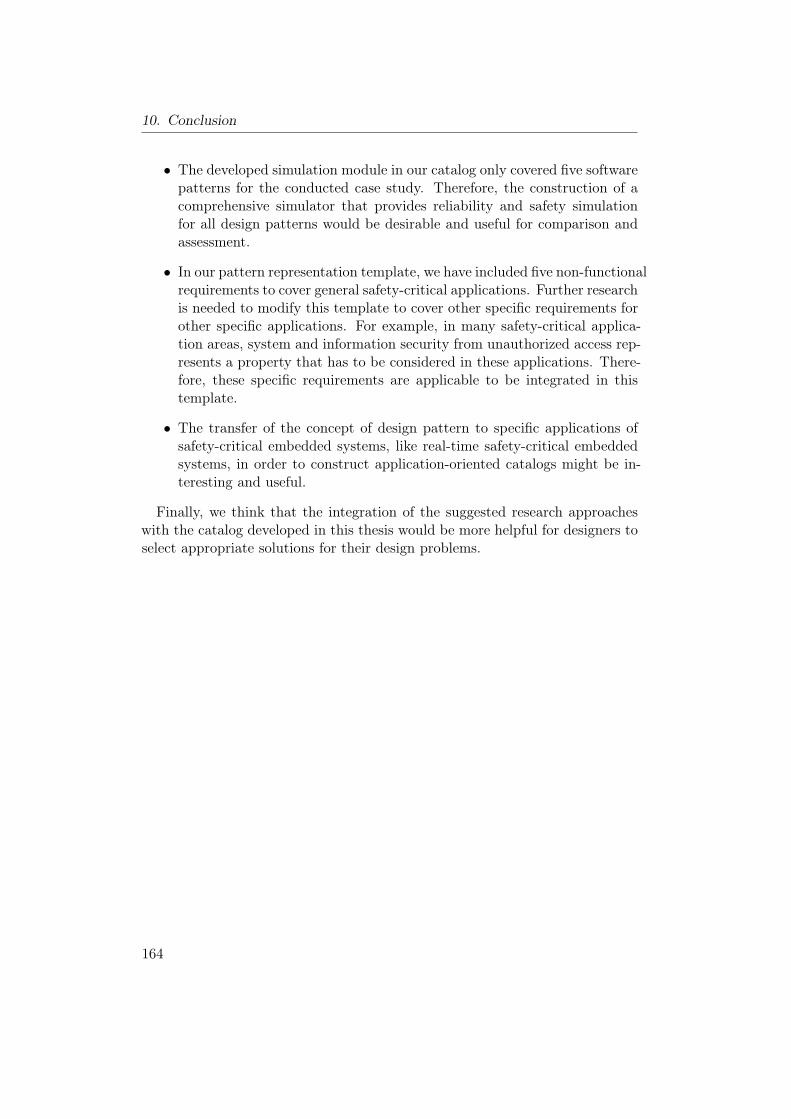
10. Conclusion
• The developed simulation module in our catalog only covered five softwarepatterns for the conducted case study. Therefore, the construction of acomprehensive simulator that provides reliability and safety simulationfor all design patterns would be desirable and useful for comparison andassessment.
• In our pattern representation template, we have included five non-functionalrequirements to cover general safety-critical applications. Further researchis needed to modify this template to cover other specific requirements forother specific applications. For example, in many safety-critical applica-tion areas, system and information security from unauthorized access rep-resents a property that has to be considered in these applications. There-fore, these specific requirements are applicable to be integrated in thistemplate.
• The transfer of the concept of design pattern to specific applications ofsafety-critical embedded systems, like real-time safety-critical embeddedsystems, in order to construct application-oriented catalogs might be in-teresting and useful.
Finally, we think that the integration of the suggested research approacheswith the catalog developed in this thesis would be more helpful for designers toselect appropriate solutions for their design problems.
164
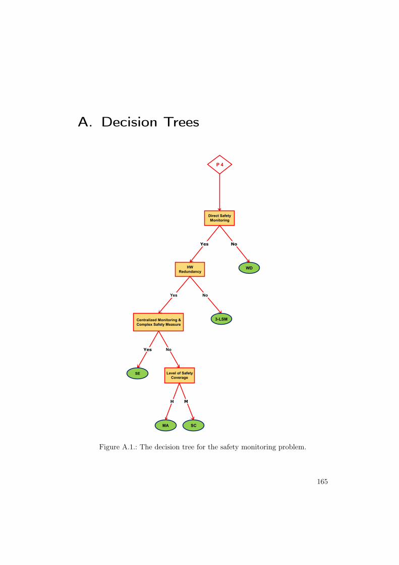
A. Decision Trees
Direct Safety
Monitoring
P 4
Yes No
WDHW
Redundancy
No
Level of Safety
CoverageSE
Yes
SCMA
H M
NoYes
Centralized Monitoring &
Complex Safety Measure
3-LSM
Figure A.1.: The decision tree for the safety monitoring problem.
165
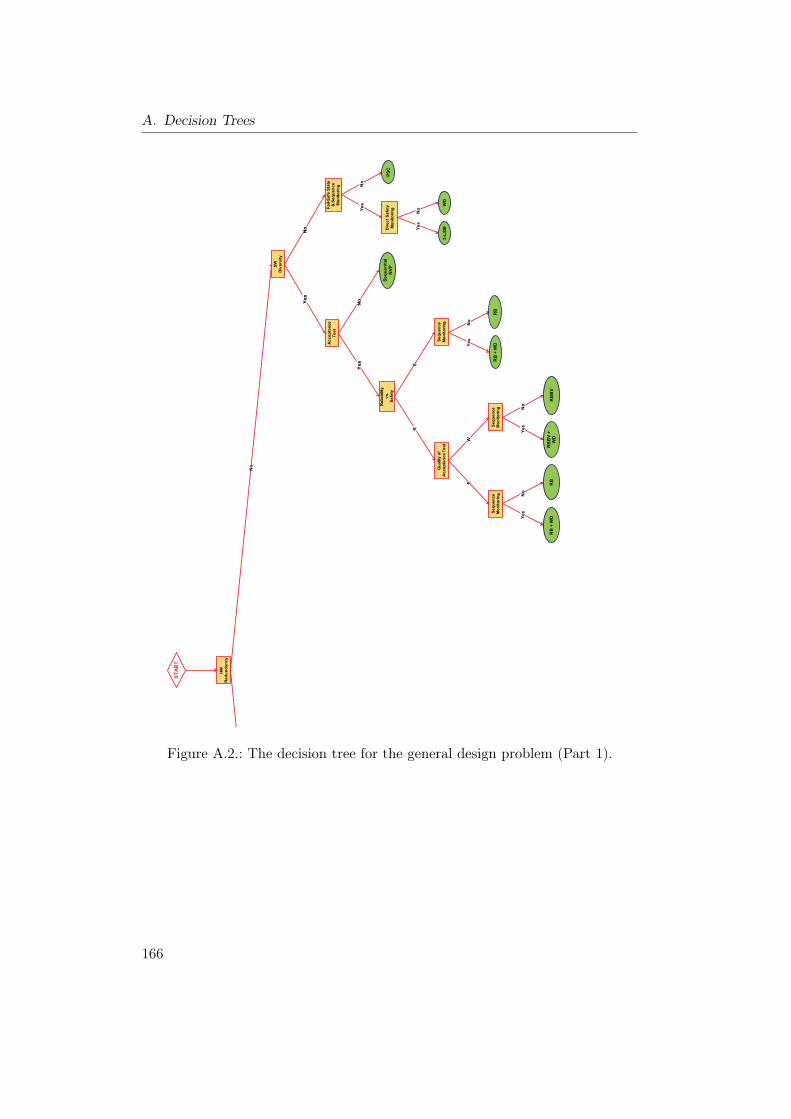
A. Decision Trees
����������
�� ��������
�����
�� ��������
$�
��
+��,�#������
����-����
����������
��!���
����
���
���
����������
��%
�#���
��-������
$./
��
$�
�� ��������
�
���
��!���
����
,���,�
$�
$�
+��,�#�
����
,���,�)
�.
���
,���,�)
$./
$��/��
�$�
���
������#���
����������
/��
$�
�
��-����
����������
1�������#
��!��������
�
�0
��-����
����������
��-����
����������
�2
�2�)�� ���
$�
�22.
�22.)
�
���
$�
�2
�2�)�� ���
$�
���
$�
�
(,���
Figure A.2.: The decision tree for the general design problem (Part 1).
166
HW
Redundancy
SW
Diversity
Availability
Yes
START
L
Centralized Monitoring &
Complex Safety Measure
No. Channels
H
n>3
HW
Diversity
HW
Diversity
HW
Diversity
3+
2+
No
SW
Diversity
Yes
SW
Diversity
HmD
HtD
Yes
No
No
No
Fail-Safe State
& Sequence
Monitoring
Acceptance
Test
Yes
Yes
Reliability
vs.
Safety
Sequential
NVP
No
No
Level of Safety
Coverage
Yes
SE
SC
MA
HM
No
SW
Diversity
Yes
SW
Diversity
Ht.TMR
Acceptance
Test
Yes
No
Ht.TMR+
NVP
Ht.TMR+
AV
Yes
No
TMR
Acceptance
Test
Yes
No
TMR+NVP
TMR+AVYes
No
Ht.m-out-n
Acceptance
Test
Yes
No
No
Fail-Safe
State
Ht.m-out-n
+AV
Yes
Yes
Acceptance
Test
m-out-n
No
Ht.m-out-n
+NVP
Ht.HW+
NSCP
Yes
No
No
Fail-Safe
State
m-out-n+
AV
Yes
m-out-n+
NVP
NSCP
Yes
No
Yes
Direct Safety
Monitoring
PSC
No
S
Sequence
Monitoring
Quality of
Acceptance Test
R
WE
Sequence
Monitoring
Sequence
Monitoring
RB
RB + WDYes
No
RBBV
RBBV+
WD
Yes
No
RB
RB + WDYes
No
Yes
No
WD
3-LSM
Figure A.3.: The decision tree for the general design problem (Part 2).
167
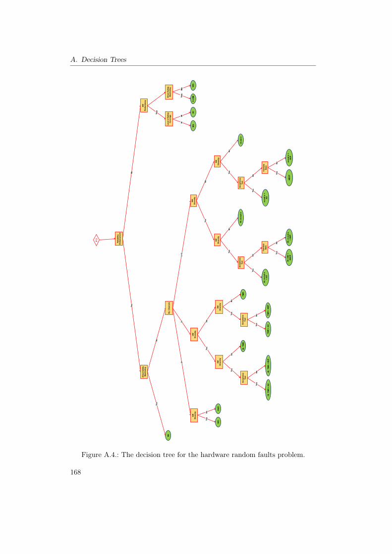
A. Decision Trees
Reliability
Enhancement
HW
Redundancy
Direct Safety
Monitoring
Yes
P 2
No. Channels
SE
Yes
No
n>3
HW
Diversity
HW
Diversity
HW
Diversity
3+
2+
No
SW
Diversity
Yes
SW
Diversity
HmD
HtD
Yes
No
No
Direct Safety
Monitoring
Level of Safety
Coverage
Yes
SC
MA
HM
No
SW
Diversity
Yes
SW
Diversity
Ht.m-out-n
Acceptance
Test
Yes
No
No
Fail-Safe
State
Ht.m-out-n
+AV
Yes
Yes
Acceptance
Test
m-out-n
No
Ht.m-out-n
+NVP
Ht.HW+
NSCP
Yes
No
No
Fail-Safe
State
m-out-n+
AV
Yes
m-out-n+
NVP
NSCP
Yes
No
Ht.TMR
Acceptance
Test
Yes
No
Ht.TMR+NVP
Ht.TMR+AVYes
No
TMR
Acceptance
Test
Yes
No
TMR+NVP
TMR+AVYes
No
WD
3-LSMYes
No
Figure A.4.: The decision tree for the hardware random faults problem.
168
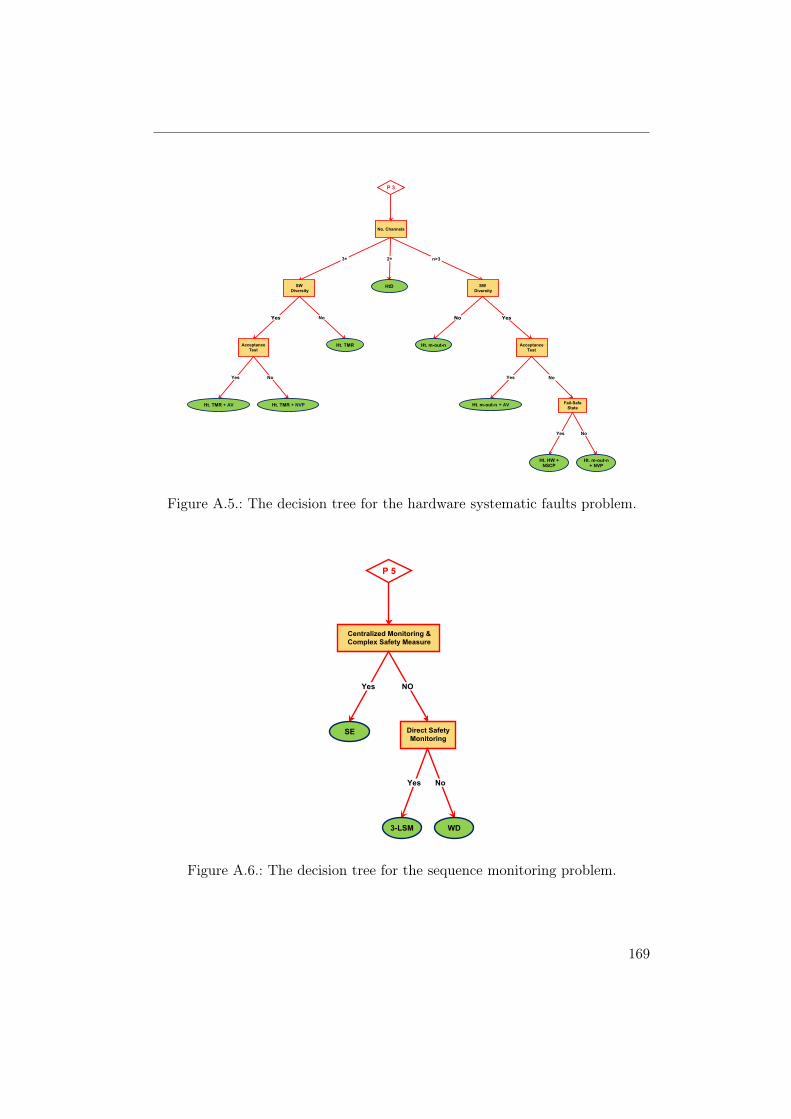
No. Channels
n>3
SW
Diversity
3+
SW
Diversity
2+
HtD
P 3
No
Ht. TMRAcceptance
Test
Yes
No
Ht. TMR + NVP
Yes
Ht. TMR + AV
Ht. m-out-n Acceptance
Test
YesNo
No
Fail-Safe
State
Yes
Ht. m-out-n + AV
Ht. m-out-n+ NVP
Ht. HW +NSCP
Yes No
Figure A.5.: The decision tree for the hardware systematic faults problem.
Centralized Monitoring &
Complex Safety Measure
NO
Direct Safety
Monitoring
Yes
SE
P 5
Yes No
WD3-LSM
Figure A.6.: The decision tree for the sequence monitoring problem.
169
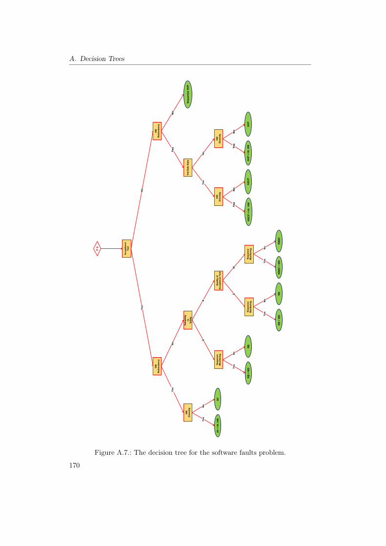
A. Decision Trees
Acceptance
Test
HW
Redundancy
HW
Redundancy
Yes
P 6
Yes
HW
Diversity
Reliability
vs.
Safety
No
S
Sequence
Monitoring
Quality of
Acceptance Test
R
WE
Sequence
Monitoring
Sequence
Monitoring
No
No
SequentialNVP
Fail-Safe State
Yes
No
Yes
HW
Diversity
HW
Diversity
RB
RB + WDYes
No
RBBV
RBBV+ WDYes
No
No
NSCP
Yes
NSCP+ Ht. HW
No
Yes
NVP
NVP+ Ht. HW
RB
RB + WDYes
No
AV
AV+ Ht. HWYes
No
Figure A.7.: The decision tree for the software faults problem.
170

Bibliography
[1] S. Adams. Functionality ala carte. Pattern Languages of Program Design,pages 7–8, 1995.
[2] C. Alexander. A Pattern Language: Towns, Buildings, Construction. Ox-ford University Press, New York, 1977.
[3] T. Anderson and R. Kerr. Recovery blocks in action: A system supportinghigh reliability. In ICSE ’76: Proceedings of the 2nd international confer-ence on Software engineering, pages 447–457, Los Alamitos, CA, USA,1976. IEEE Computer Society Press.
[4] A. Armoush, E. Beckschulze, and S. Kowalewski. Safety assessment ofdesign patterns for safety-critical embedded systems. In 35th EuromicroConference on Software Engineering and Advanced Applications (SEAA2009). IEEE CS, Aug. 2009.
[5] A. Armoush and S. Kowalewski. Safety recommendations for safety-critical design patterns. In Design of Dependable Critical Systems (DDCS)In the framework of the SAFECOMP2009, 2009.
[6] A. Armoush, F. Salewski, and S. Kowalewski. Effective pattern represen-tation for safety critical embedded systems. In 2008 International Con-ference on Computer Science and Software Engineering, volume 4, pages91–97. IEEE CS, Dec. 2008.
[7] A. Armoush, F. Salewski, and S. Kowalewski. A hybrid fault tolerancemethod for recovery block with a weak acceptance test. In The 5thIEEE/IFIP International Conference on Embedded and Ubiquitous Com-puting (EUC 2008), volume 1, pages 484–491. IEEE CS, Dec. 2008.
[8] A. Armoush, F. Salewski, and S. Kowalewski. Recovery block with backupvoting: A new pattern with extended representation for safety critical em-bedded systems. In 11th International Conference on Information Tech-nology (ICIT 2008), pages 232–237. IEEE CS, Dec. 2008.
[9] A. Armoush, F. Salewski, and S. Kowalewski. Design pattern representa-tion for safety-critical embedded systems. Journal of Software Engineeringand Applications (JSEA), 2(1):1–12, April 2009.
171
Bibliography
[10] A. Athavale. Performance evaluation of hybrid voting schemes. Master’sthesis, North Carolina State University, Department of Computer Science,1989.
[11] A. Avizienis. The N-version approach to fault-tolerant software. IEEETransactions on Software Engineering, 11(12):1491–1501, 1985.
[12] A. Avizienis. The Methodology of N-version Programming, chapter Soft-ware Fault Tolerance, pages 23–46. Wiley, New York, 1995.
[13] A. Avizienis and L. Chen. On the implementation of N-version program-ming for software fault tolerance during execution. In IEEE ComputerSoftware and Applications Conference 77, pages 149–155. IEEE Press,1977.
[14] A. Avizienis, J. Laprie, and B. Randell. Fundamental concepts of depend-ability. Technical Report N01145, LAAS-CNRS, April 2001.
[15] A. Avizienis, J. Laprie, B. Randell, and C. Landwehr. Basic concepts andtaxonomy of dependable and secure computing. IEEE Transactions onDependable and Secure Computing, 1(1):11–33, 2004.
[16] K. Beck and W. Cunningham. Using pattern langugages for object-oriented programs. In Position Paper for the Specification and Design forObject-Oriented Programming Workshop, The 3rd Conference on Object-Oriented Programming Systems, Languages and Applications, Orlando,USA, 1987.
[17] F. Bederna and T. Zeller. United States Patent No. 5,880,568: Methodand arrangement for controlling the drive unit of a vehicle, March 1999.
[18] A. Berger. Embedded systems design: an introduction to processes, tools,and techniques. Focal Press, 2nd edition, 2002.
[19] A. Birolini. Reliability Engineering, Theory and Practice. Springer, 5thedition, 2007.
[20] F. Bitsch. Safety patterns - the key to formal specification of safety re-quirements. In the 20th International Conference on Computer Safety,Reliability and Security (SAFECOMP ’01), pages 176–189, London, UK,2001. Springer-Verlag.
[21] A. Burns and A. Wellings. Real-Time Systems and Programming Lan-guages. Addison-Wesley Longman Publishing Co., Inc., Boston, MA, USA,4th edition, 2009.
172
Bibliography
[22] F. Buschmann. The Master-Slave Pattern. ACM Press/Addison-WesleyPublishing Co., New York, NY, USA, 1995.
[23] F. Buschmann, R. Meunier, H. Rohnert, P. Sommerlad, and M. Stal.Pattern-oriented software architecture: a system of patterns. John Wiley& Sons, Inc. New York, 1996.
[24] G. Buttazzo. Research trends in real-time computing for embedded sys-tems. SIGBED Rev., 3(3):1–10, 2006.
[25] L. Chen and A. Avizienis. N-version programming: A fault-tolerance ap-proach to reliability of software operation. In Twenty-Fifth InternationalSymposium on Fault-Tolerant Computing, “Highlights from Twenty-FiveYears”, page 113, June 27–30 1995.
[26] P. P.-S. Chen. The entity-relationship model: Toward a unified view ofdata. ACM Transactions on Database Systems, 1:9–36, 1976.
[27] J. Cleland-Huang and D. Schmelzer. Dynamically tracing non-functionalrequirements through design pattern invariants. In Workshop on Trace-ability in Emerging Forms of Software Engineering, in conjunction withIEEE International Conference on Automated Software Engineering, Oc-tober 2003.
[28] P. Coad. Object-oriented patterns. Communications of the ACM,35(9):152–159, 1992.
[29] J. O. Coplien. Advanced C++ programming styles and idioms. Addison-Wesley Longman Publishing Co., Inc., Boston, MA, USA, 1992.
[30] J. O. Coplien. Idioms and patterns as architectural literature. IEEESoftw., 14(1):36–42, 1997.
[31] R. Damaševičius, G. Majauskas, and V. Štuikys. Application of designpatterns for hardware design. In DAC ’03: Proceedings of the 40th annualDesign Automation Conference, pages 48–53, New York, NY, USA, 2003.ACM.
[32] R. Damaševičius and V. Štuikys. Application of UML for hardware designbased on design process model. In ASP-DAC ’04: Proceedings of the 2004Asia and South Pacific Design Automation Conference, pages 244–249,Piscataway, NJ, USA, 2004. IEEE Press.
[33] F. Daniels, K. Kim, and M. Vouk. The reliable hybrid pattern: a general-ized software fault tolerant design pattern. In Conference PloP’97, pages1–9, 1997.
173
Bibliography
[34] T. DeLong, D. Smith, and B. Johnson. Dependability metrics to assesssafety-critical systems. IEEE Transactions on Reliability, 54(3):498–505,2005.
[35] DOD. MIL-STD 882D–Standard Practice for System Safety. US Depart-ment of Defense (DOD), 2000.
[36] B. P. Douglass. Doing Hard Time: Developing Real-Time System withUML, Objects, Frameworks, and Pattern. Addison-Wesley, New York,1999.
[37] B. P. Douglass. Real-Time Design Patterns: Robust Scalable Architecturefor Real-Time Systems. Addison-Wesley, New York, Boston, MA, USA,2002.
[38] W. R. Dunn. Practical Design of Safety-Critical Computer Systems. Re-liability Press, 2002.
[39] W. R. Dunn. Designing safety-critical computer systems. Computer,36(11):40–46, 2003.
[40] J. Fletcher and J. Cleland-Huang. Softgoal traceability patterns. InISSRE ’06: Proceedings of the 17th International Symposium on Soft-ware Reliability Engineering, pages 363–374, Washington, DC, USA, 2006.IEEE Computer Society.
[41] E. Gamma, R. Helm, R. Johnson, and J. Vlissides. Design Patterns:Elements of Reusable Object-Oriented Software. Addison-Wesley, Boston,MA, USA, 1997.
[42] A. Grinin. Development of a catalog of design patterns for safety-criticalembedded systems. Diploma thesis, RWTH Aachen University, 2009.
[43] D. Gross and E. Yu. From non-functional requirements to design throughpatterns. Requirements Engineering, 6(1):18–36, 2001.
[44] L. Grunpke. Transformational patterns for the improvement of safetyproperties in architectural specification. In Proceeding of the VikingPLoPO3, Bergen, Norway, 2003.
[45] R. Hanmer. Patterns for Fault Tolerant Software. Wiley Publishing, 2007.
[46] IEC61508. Functional safety for electrical / electronic / programmableelectronic safety-related systems. International Electrotechnical Comis-sion, 1998.
174
Bibliography
[47] U. Isaksen, J. P. Bowen, and N. Nissanke. System and software safety incritical systems. Technical Report RUCS/97/TR/062/A, The Universityof Reading, UK, 1999.
[48] ISO. ISO/WD 26262 - Road vehicles - Functional Safety. InternationalOrganization for Standardization, working draft (2007).
[49] K. Kanoun, M. Kaaniche, C. Beounes, J.-C. Laprie, and J. Arlat. Relia-bility growth of fault-tolerant software. IEEE Transactions on Reliability,42(2):205–219, 1993.
[50] J. Kelly, T. McVittie, and W. Yamamoto. Implementing design diversityto achieve fault tolerance. IEEE Transactions on Software, 8(4):61–71,1991.
[51] T. P. Kelly. Arguing Safety - A Systematic Approach to Managing SafetyCases. PhD thesis, Department of Computer Science - University of York,1998.
[52] K. Kim. Distributed execution of recovery block: An approach to uni-form treatment of hardware and software faults. In Proc. Fourth IEEEInt’l Conf. Distributed Computing Systems (ICDCS), pages 526–532, SanFrancisco, Calif, May 1984.
[53] K. Kim and H. Welch. Distributed execution of recovery blocks: an ap-proach for uniform treatment of hardware and software faults in real-timeapplications. IEEE Transactions on Computers, 38(5):626–636, May 1989.
[54] J. C. Knight. Safety critical systems: challenges and directions. In ICSE’02: Proceedings of the 24th International Conference on Software Engi-neering, pages 547–550, New York, NY, USA, 2002. ACM.
[55] S. Konrad and B. H. C. Cheng. Requirements patterns for embeddedsystems. In Proceedings of the 10th Anniversary IEEE Joint Interna-tional Conference on Requirements Engineering, pages 127–136, Washing-ton, DC, USA, 2002. IEEE Computer Society.
[56] S. Konrad, B. H. C. Cheng, and L. A. Campbell. Object analysis pat-terns for embedded systems. IEEE Transactions on Software Engineering,30(12):970–992, 2004.
[57] I. Koren and C. Krishna. Fault-Tolerant Systems. Morgan Kaufmann,San Francisco, 2007.
175
Bibliography
[58] R. Lajoie and R. Keller. Object-Oriented Technology for Database andSoftware Systems, chapter Design and Reuse in Object-Oriented Frame-works: Patterns, Contracts and Motifs in Concert, pages 295–312. WorldScientific Publishing, Singapore, 1995.
[59] J. Laprie, J. Arlat, C. Béounes, and K. Kanoun. Definition and analysis ofhardware- and software-fault-tolerant architectures. IEEE Transactionson Computer, 23(7):39–51, July 1990.
[60] J. Laprie, J. Arlat, C. Béounes, and K. Kanoun. Architectural Issuesin Software Fault-Tolerance, Software Fault Tolerance, chapter 3, pages47–80. John Wiley & Sons. Ltd., New York, USA, 1995.
[61] J. Laprie, J. Arlat, C. Béounes, K. Kanoun, and C. Hourtolle. Hardwareand software fault tolerance: Definition and analysis of architectural so-lutions. In Proceedings of the 17th IEEE International Symposium onFault-Tolerant Computing, pages 116–121. IEEE Press, 1987.
[62] J.-C. Laprie. Dependable computing and fault tolerance: Concepts andterminology. In 25th International Symposium on Fault-Tolerant Comput-ing, 1995, “Highlights from Twenty-Five Years”, pages 2–11, Jun 1995.
[63] G. Latif-Shabgahi, J. Bass, and S. Bennett. A taxonomy for softwarevoting algorithms used in safety-critical systems. IEEE Transactions onReliability, 53(3):319–328, Sept. 2004.
[64] T.-Y. Lee and P.-A. Hsiung. Embedded software synthesis and prototyp-ing. Consumer Electronics, IEEE Transactions on, 50(1):386–392, Feb2004.
[65] Y.-W. Leung. Maximum likelihood voting for fault-tolerant softwarewith finite output-space. IEEE Transactions on Reliability, 44(3):419–427, Sept. 1995.
[66] N. G. Leveson. Safeware: system safety and computers. ACM, New York,NY, USA, 1995.
[67] R. Lutz. Software engineering for safety: a roadmap. In ICSE ’00: Pro-ceedings of the Conference on The Future of Software Engineering, pages213–226, New York, NY, USA, 2000. ACM.
[68] M. Lyu. Handbook of Software Reliability Engineering. McGraw-Hill andIEEE Computer Society Press, New York, 1996.
176
Bibliography
[69] D. Manolescu, M. Voelter, and J. Noble. Pattern Languages of ProgramDesign 5. Addison-Wesley Professional, 2005.
[70] M. Marseguerra and E. Zio. Basics of the Monte Carlo method with ap-plication to system reliability. LiLoLe–Verlag, Berlin, 2002.
[71] P. Marwedel. Embedded System Design. Springer-Verlag New York, Inc.,Secaucus, NJ, USA, 2nd edition, 2006.
[72] D. McAllister, C.-E. Sun, and M. Vouk. Reliability of voting in fault-tolerant software systems for small output-spaces. IEEE Transactions onReliability, 39(5):524–534, Dec. 1990.
[73] MISRA. Development Guidelines for Vehicle Based Software. The MotorIndustry Software Reliability Association, November 1994.
[74] T. Noergaard. Embedded Systems Architecture: A Comprehensive Guidefor Engineers and Programmers. Newnes, 2005.
[75] B. Parhami. Voting algorithms. IEEE Transactions on Reliability,43(4):617–629, Dec. 1994.
[76] B. Parhami. Design of reliable software via general combination of N-version programming and acceptance testing. In Proc. Seventh Interna-tional Symposium on Software Reliability Engineering, pages 104–109, 30Oct.–2 Nov. 1996.
[77] J. K. Peckol. Embedded Systems: A Contemporary Design Tool. WileyPublishing, 2007.
[78] M. Pont. Patterns for Time-Triggered Embedded Systems: Building re-liable applications with the 8051 family of microcontrollers. ACM Press,New York, 2001.
[79] M. J. Pont and M. P. Banner. Designing embedded systems using patterns:a case study. Journal of Systems and Software, 71(3):201–213, 2004.
[80] G. Pucci. On the modelling and testing of recovery block structures. InProc. 20th International Symposium Fault-Tolerant Computing FTCS-20,pages 356–363, 26–28 June 1990.
[81] L. L. Pullum. Software fault tolerance techniques and implementation.Artech House, Inc., Norwood, MA, USA, 2001.
[82] B. Randell. System structure for software fault tolerance. IEEE Transac-tion in Software Engineering, 1(2):220–232, 1975.
177
Bibliography
[83] B. Randell. Dependability, structure and infrastructure. Technical ReportCS-TR-877, School of Computing Science, University of Newcastle uponTyne, November 2004.
[84] B. Randell, J. Horning, H. Lauer, and P. Melliar-Smith. A program struc-ture for error detection and recovery. LNCS, 16:171–187, 1974.
[85] B. Randell and J. Xu. Software Fault Tolerance, chapter The Evolutionof the Recovery Block Concept. John Wiley & Sons, New York, 1995.
[86] F. Redmill. IEC 61508: Principles and use in the management of safety.IEE Computing and Control Engineering, 9(10):205–213, 1998.
[87] D. Riehle and H. Züllighoven. A pattern language for tool constructionand integration based on the tools and materials metaphor. Pattern lan-guages of program design, pages 9–42, 1995.
[88] F. Rincon, F. Moya, J. Barba, and J. C. Lopez. Model reuse throughhardware design patterns. In DATE ’05: Proceedings of the conferenceon Design, Automation and Test in Europe, pages 324–329, Washington,DC, USA, 2005. IEEE Computer Society.
[89] L. Rising. Design patterns in communications software. Cambridge Uni-versity Press, New York, NY, USA, 2001.
[90] S. Robertson and J. Robertson. Mastering the Requirements Process (2ndEdition). Addison-Wesley Professional, 2006.
[91] RTCA. DO-178B, Software Considerations in Airborne Systems andEquipment Certification. RTCA, Inc., 1992.
[92] RTCA. DO-254, Design Assurance Guidance for Airborne ElectronicHardware. RTCA, Inc., 2000.
[93] B. Rubel. Patterns for generating a layered architecture. Pattern lan-guages of program design, pages 119–128, 1995.
[94] M. Schumacher, E. Fernandez-Buglioni, D. Hybertson, F. Buschmann,and P. Sommerlad. Security Patterns : Integrating Security and SystemsEngineering. John Wiley & Sons, March 2006.
[95] L. Sha. Using simplicity to control complexity. IEEE Software, 18(4):20–28, July–Aug. 2001.
178
Bibliography
[96] D. J. Smith and K. G. L. Simpson. Functional safety: A straightforwardguide to applying the IEC 61508 and related standards. Elsevier, Burling-ton, U.K., 2nd edition, 2005.
[97] N. Storey. Safety-Critical Computer System. Addison-Wesley, Harlow,England, 1996.
[98] N. F. Vaidya and D. K. Pradhan. Fault-tolerant design strategies for highreliability and safety. IEEE Transactions on Computers, 42(10):1195–1206, 1993.
[99] W. H. Wolf. Hardware-software co-design of embedded systems. Proceed-ings of the IEEE, 82(7):967–989, July 1994.
[100] W. Wu and T. Kelly. Safety tactics for software architecture design. Inthe 28th Annual International Computer Software and Applications Con-ference (COMPSAC ’04), pages 368–375, Washington, DC, USA, 2004.IEEE Computer Society.
[101] L. Xu, H. Ziv, D. Richardson, and T. A. Alspaugh. An architecturalpattern for non-functional dependability requirements. ACM SIGSOFTSoftware Engineering Notes, 30(4):1–6, 2005.
[102] N. Yoshida. Design patterns applied to object-oriented SOC design. In10th Workshop on Synthesis and System Integration of Mixed Technologies(SASIMI 2001), Nara, Japan, Oct. 2001.
[103] N. Yoshioka, H. Washizaki, and K. Maruyama. A survey on securitypatterns. Progress in Informatics:, 5:35–47, 2009.
[104] Y. Yu and B. Johnson. The quantitative safety assessment for safety-critical software. In Proc. 29th Annual IEEE/NASA Software EngineeringWorkshop, pages 150–162, 2005.
179

Bibliography
180
Curriculum Vitae
Name Ashraf Armoush
Date of birth 11.11.1977
Place of birth Awarta, West Bank
2007 – 2010 Research assistant at the Embedded Software Laboratory atRWTH Aachen University, Germany
2003 – 2006 Instructor at An-Najah National University, Palestine
2001 – 2003 Study of master in computer science at the University ofJordan, Jordan
2000 – 2001 Teaching assistant at An-Najah National University,Palestine
1995 – 2000 Study of electrical engineering at An-Najah National Univer-sity, Palestine
1993 – 1995 Houwarah Boys Secondary School, Palestine
1983 – 1993 Awarta Elementary School, Palestine
181