Embed Size (px)
Citation preview
1
Design procedure and experimental study on fibre reinforced concrete
segmental rings for vertical shafts
Lin Liao a,b, Albert de la Fuente a, * , Sergio Cavalaro a, Antonio Aguado a
a Civil and Environmental Engineering Department, Universitat Politècnica de Catalunya (UPC
BarcelonaTECH), Jordi Girona 1-3, 08034, Barcelona, Spain.
b Department of Underground Engineering, Taiyuan University of Technology, 79 Yingze West
Street, 030024 Taiyuan, China
* Corresponding author. Tel.: +34-93-401-65-15. E-mail: [email protected]
Keywords: MC 2010; optimal design; vertical shafts; precast segments; FRC
Abstract Structural fibres are used to replace partially or totally the passive reinforcement in precast
concrete segments for tunnel linings constructed with TBM, showing several advantages. Fibre
reinforced concrete (FRC) could also be applied with similar benefits to vertical shafts.
However, to the author's knowledge, this material has not been used in such application yet.
The Model Code 2010 gathers an approach for the design of FRC structural elements. This
approach should be adapted according to the structural needs of precast segment, for which the
transient load stages are often the most critical and specific ductility requirements should be
established. The objective of this paper is twofold: propose a general analytical formulation to
assess the minimum mechanical requirements that FRC must fulfil in case of partial or complete
substitution of the steel rebars and confirm that it is possible to replace the rebars by using fibres
in vertical shaft linings. First, the general analytical formulation is proposed. Then, the
segments of the Montcada vertical shaft (Barcelona) are redesigned considering the total
substitution of the traditional reinforcement by fibres. Finally, two full-scale tests of the FRC
precast segments were performed to verify the suitability of the analytical formulation
proposed.
1 INTRODUCTION
Structural fibres are commonly used in precast segments for the lining of tunnels constructed
with tunnel boring machines (TBM). These structures usually remain under compression in
service, presenting tensile stresses primarily during transient stages (demoulding, storage,
transport, handling, and installation). Under these conditions, the partial or even the complete
replacement of traditional bar reinforcement by an adequate amount of structural fibres
becomes attractive from an economic and technic standpoint.
Currently, several codes and guidelines include fibre reinforced concrete (FRC) as a structural
material; highlighted among them the MC 2010 [1]. Furthermore, many experimental
2
campaigns [2–9] from the literature (Table 1) have focused on the production, full-scale
bending tests, and numeric simulations of segments made of concrete with compressive
strengths fc ranging from 20 to 150 N/mm2 and structural fibre contents (Cf) ranging from 30
to 236 kg/m3. Moreover [10–16] present a set of real experiences in tunnels constructed with
TBM in which FRC is used. These experiences have promoted the application of FRC,
demonstrating that the material is competitive at the structural level compared with other
traditional solution
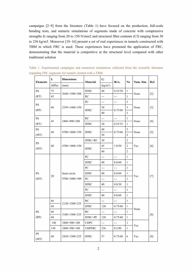
Table 1. Experimental campaigns and numerical simulations collected from the scientific literature
regarding FRC segments for tunnels created with a TBM.
Elements fc Dimensions
Material Cf
Фf/λf No Num. Sim. Ref. (MPa) (mm) (kg/m3)
PS
(RT)
75 3640×1500×200
SFRC 40 0.35/30 1 None [2]
45 RC --- --- 1
PS
(RP) 60 2359×1400×350
PC --- --- 3
None [3] SFRC
30 0.75/60
3
40 3
PS
(RT) 45 2406×900×200
RC --- --- 1 None [4]
SFRC 20 0.55/35 1
PS
(MT) 60 4700×1800×350 SFRC
40 0.75/60
2 None [5]
50 2
PS
(MT) 60 4700×1800×350
SFRC+RC 30
1.0/50
2
Yes [6] SFRC
45 2
60 2
PS
(MT) 20
Semi-circle
9700×1000×300
PC --- --- 1
Yes [7]
SFRC 40 0.8/60 1
PC --- --- 1
SFRC 40 0.8/60 1
PC --- --- 1
SFRC 40 0.8/30 1
PC --- --- 1
SFRC 40 0.8/60 1
PS
(RP)
66 2120×1500×235
RC --- --- 1
None
[8]
68 SFRC 120 0.75/60 1
66 3180×1500×235
RC --- --- 1
68 SFRC+PF 120 0.75/60 1
140 1000×500×100 UHPC --- --- 1 Yes
150 1000×500×100 UHPFRC 236 0.2/80 1
PS
(MT) 68 2438×1500×235 SFRC 57 0.75/60 6 Yes [9]
3
PS: precast segment; RT: Road Tunnel; RP: Research Project; MT: Metro Tunnel; fc: concrete compressive strength; SFRC: Steel
Fibre Reinforced Concrete; RC: Reinforced Concrete; UHPC: Ultra High Performance Concrete; UHPFRC: UltraHigh Fibre
Reinforced Concrete; PF: Plastic Fibres; Φf: cross section diameter of the fibres; λf: aspect ratio of the fibres
Until now, the design of FRC segments has been addressed by means of numerical methods
[3,17–27]. To the authors' best knowledge, no analytical expression that describes the design
of segments reinforced only with fibres or with hybrid reinforcement (fibre + bars) is found in
the literature. Furthermore, the authors have been unable to find any reference in which these
types of segments are used in vertical shafts constructed with a vertical shaft machine (VSM).
Like in many tunnels, in this case the segments are generally subjected to reduced stresses
during the transitional phases and compression predominates during service. Therefore, despite
the absence of previous experiences, the use of structural fibres instead of bars may also be
competitive
The aim of this study is to provide a response to the two absences mentioned in the previous
paragraph. On one hand, the objective is to demonstrate that the complete replacement of the
bar reinforcement by fibres is also possible in shaft linings constructed with VSM. On the other
hand, the objective is to propose an analytical and general formulation to assess the minimum
mechanical requirements that the FRC must fulfil in elements with complete or partial
substitutions of the traditional reinforcement.
First, the analytical formulation based on the MC 2010 is proposed for the structural design of
FRC segments. This formulation is then applied to the redesign of the segments from Montcada
Shaft, which was originally conceived with traditional reinforcement. After that, in
the context of full-scale construction work (Montcada Shaft, Barcelona) and a research project,
a characterization campaign of conventional and self-compacting concretes reinforced with
fibre quantities (Cf) between 30 and 60 kg/m3 was performed to evaluate the optimum amount
for the complete removal of the traditional reinforcement. Finally, an experimental campaign
of full-scale segments subjected to bending was performed with both concrete types to verify
the ductile behaviour until failure. This study widens the field of application of FRC,
demonstrating the feasibility of a new use. Moreover, it shows new formulations that might
support engineers towards the optimal structural design of this type of structures or others
constructed with FRC.
2 BRIEF OVERVIEW ON FRC DESIGN
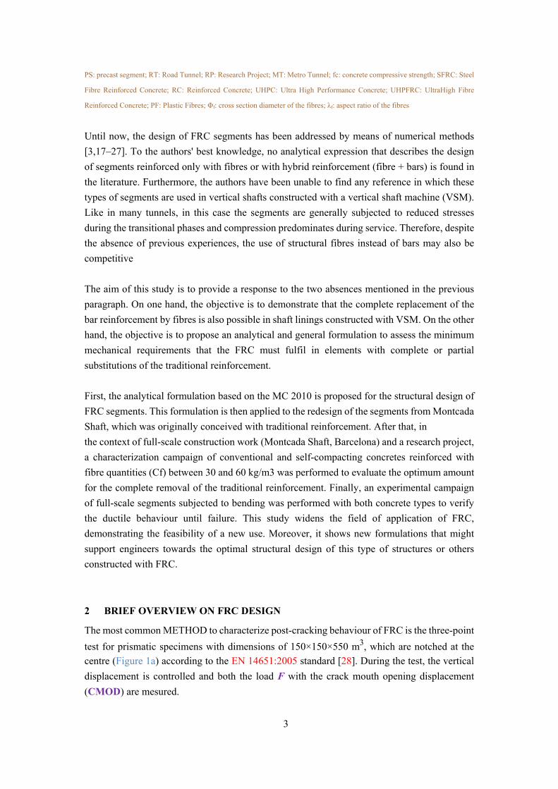
The most common METHOD to characterize post-cracking behaviour of FRC is the three-point
test for prismatic specimens with dimensions of 150×150×550 m3, which are notched at the
centre (Figure 1a) according to the EN 14651:2005 standard [28]. During the test, the vertical
displacement is controlled and both the load F with the crack mouth opening displacement
(CMOD) are mesured.
4
Figure 1. Three-point test in notched prismatic beams: (a) test configuration (mm) and (b) F – CMOD
generic curve
The F–CMOD curve obtained (Fig. 1b) may be used to deduce the tensile constitutive law σ–ε
of the FRC. The stresses σ are obtained from the residual tensile strength fRi. The classification
proposed in MC 2010 is based on the characteristic values of the residual tensile strength for
CMOD = 0.5 mm (fR1k) and CMOD = 2.5 mm (fR3k). In this regard, the FRC strength class
is specified using fR1k to represent the strength interval and the letter (a, b, c, d, or e) to
represent the fR3k/fR1k ratio. The strength interval fR1k is established by using a number from
the following series: 1.0–1.5–2.0–2.5–3.0–4.0–4.5–5.0–6.0–7.0–8.0 in N/mm2.
The fR3k/fR1k ratios are in accordance with the following series: a) if 0.5 ≤ fR3k/fR1k 0.7;
b) if 0.7 ≤ fR3k/fR1k 0.9; c) if 0.9 ≤ fR3k/fR1k 1.1; d) if 1.1 ≤ fR3k/fR1k 1.3; and e) if f
R3k/fR1k ≥1.3. In addition to that, the MC 2010 establishes that when the goal is to replace
either partially or completely the traditional reinforcement with an equivalent quantity of
structural fibres in ultimate limit state (ULS), the following conditions must be satisfied:
fR1k/fLk 0.4 and fR3k/fR1k 0.5.
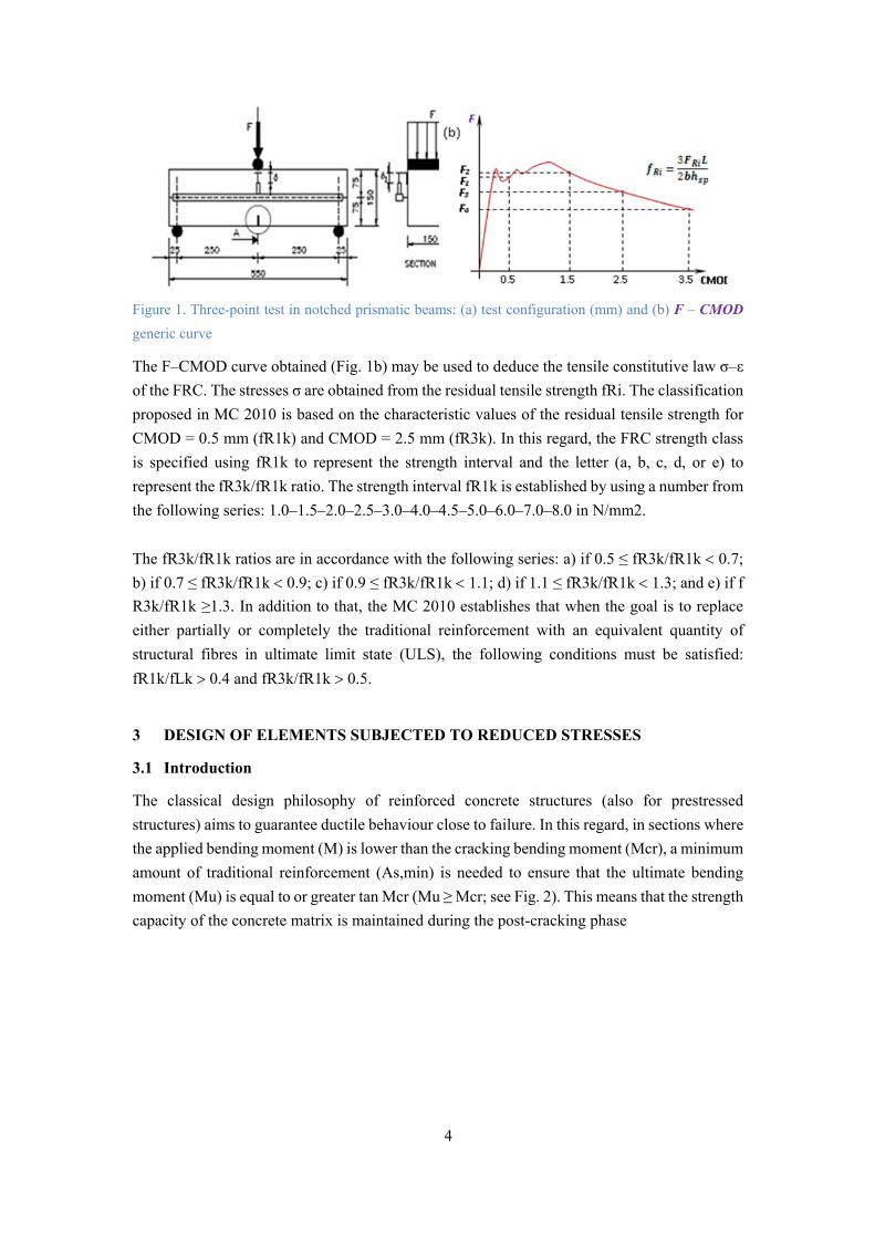
3 DESIGN OF ELEMENTS SUBJECTED TO REDUCED STRESSES
3.1 Introduction
The classical design philosophy of reinforced concrete structures (also for prestressed
structures) aims to guarantee ductile behaviour close to failure. In this regard, in sections where
the applied bending moment (M) is lower than the cracking bending moment (Mcr), a minimum
amount of traditional reinforcement (As,min) is needed to ensure that the ultimate bending
moment (Mu) is equal to or greater tan Mcr (Mu ≥ Mcr; see Fig. 2). This means that the strength
capacity of the concrete matrix is maintained during the post-cracking phase
5
Figure 2. Moment M – Curvature χ diagram to illustrate sectional response as a function of the degree of
reinforcement.
This approach has been adopted in the MC 2010 and in other national codes to evaluate As,min.
Eq. (1) shows the minimum amount of traditional reinforcement needed to fulfil the ductility
requirements in rectangular sections. This equation is derived by matching the mean value of
Mcr (Mcrm) with Mu, assuming that in ULS the arm (z) equals 0.8 of the height (h), the distance
to the gravity centre of the bars in tension (d) equals 0.9 of h, and the partial safety factor of the
steel bar (γs) is 1.15. In this regard, as discussed in [29], adopting mean values of Mcr leads to
As,min on the safe side.
bdf
fA
yk
flctms
,min, 26.0 (Eq. 1)
In the FRC elements, assuming mean values of Mcr for this type of approach usually leads to
high minimum fibres contents (Cf,min), which could be unfeasible at a technical and economic
standpoint. In the case of segments for tunnel linings, an extensive discussion of this issue may
be found in [30]. Tacking that into account, the design values of Mcr and tension strength in
flexion fct,fl (Mcrd and fctd,fl, respectively) are assumed for the evaluation of As,min and fR3k,min to
ensure the ductility of the segment in case such the design value of the moment (Md) exceeds
Mcrd.
3.2 Formula to evaluate minimum reinforcement requirements
In contrast to bar-reinforced concrete sections (for which there are formulas, such as Eq. 1 to
evaluate As,min), for FRC sections and sections with hybrid reinforcement (As + Cf), there are
no analytical formulas to obtain values of fR3min to satisfy the minimum ductility requirements.
In this regard, the recommendations proposed in MC 2010 as well as in the classical approach,
which consists of ensure that Mu ≥ Mcr,d.
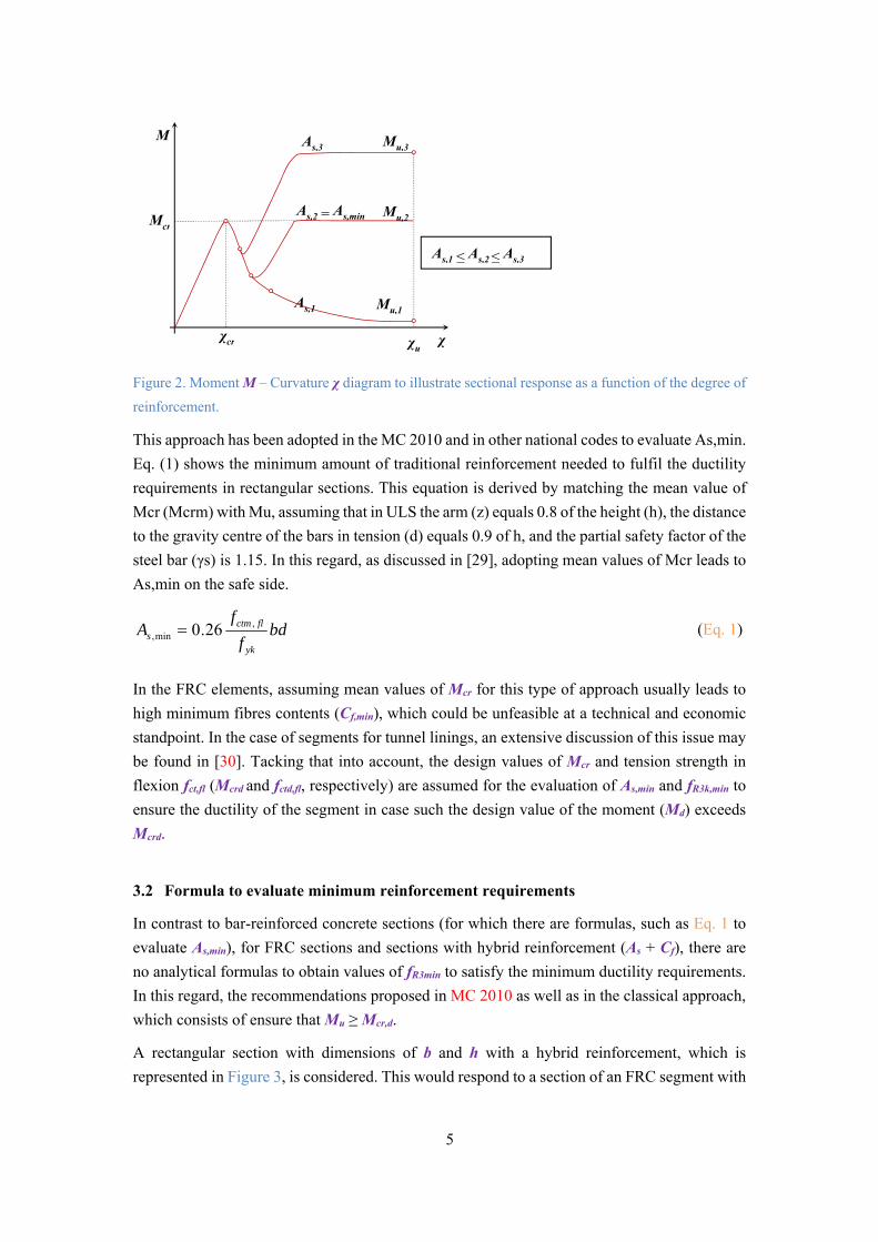
A rectangular section with dimensions of b and h with a hybrid reinforcement, which is
represented in Figure 3, is considered. This would respond to a section of an FRC segment with
M
χ
χcr
Mcr
Mu,2
Mu,3
Mu,1
χu
As,1
As,2 = As,min
As,3
As,1 ≤ As,2≤ As,3

6
Mu
fFtud = fR3d/3
h
b
Ts
Tc
CdG
FRC
As
d
localised reinforcement to confine the concrete during the jack thrust phase and to control
possible cracking due to bursting and splitting [31-37].
Figure 3. Cross-section of a segment with hybrid reinforcement (As + Cf).
Notice that the longitudinal bars and the fibres contribute to the flexural strength of the cross-
section. The fR3 required will depend on the amount of traditional reinforcement used. To
assess the characteristic value of fR3 (fR3k), a sectional analysis is proposed and the following
hypotheses are assumed.
The behaviour of FRC subjected to tensile stresses is simulated through the perfect
plastic constitutive diagram proposed in MC 2010 and defined by the design value of
the ultimate tensile residual strength of the material (fFtud) that should equal fR3d/3. The
value of fR3d should be obtained by the division of the corresponding characteristic
value (fRk3) by the partial safety factor for the FRC under tensile forces (γFRC).
Since sections are weakly reinforced, the neutral line in bending for ULS is located
near the upper fibre. The same is true for the resultant forcé Cc of the compressive
stresses, which should also be concentrated in the upper fibre.
The passive reinforcement reaches the yielding limit and develops tensile forcé Ts =
As·fyd where fyd = fyk/γs and fyk (fyd and fyd) are the characteristic and design values of the
elastic limit of steel, respectively. The reinforcement near the upper fibre is not taken
into account in the analysis. This hypothesis is on the safe side.
The equilibrium equations of the horizontal loads (Eq. 2) and of the moments with respect to
the section centre of gravity (Eq. 3) are imposed. By combining Eqs. 2 and 3, Eq. 4 is obtained.
0 fsc TTC (ec.2)
22
hdT
hCM scu (ec. 3)
dfAbh
fM ydsFtudu 2
2
(ec. 4)
Considering that for all the loading stages Md ≤ Mcrd only a minimum amount of reinforcement
is required to ensure ductile failure. In other words, the condition of Mu ≥ Mcrd should be
imposed. Mcrd can be evaluated by a linear elastic calculation that, for rectangular sections, in
mathematically represented trough Eq. 5.
7
flctdcrd fbh
M ,
2
6 (ec. 5)
By combining Eqs. (4) and (5) and considering the relationship ξ = d/h and ρs = As/Ac, (the
geometric quantity of passive reinforcement). Eq. 6, is obtained, to asses fR3k. In this equation,
γc is the partial safety factor for concrete
flctkflctk
s
yk
sc
HRFkR f
f
f
f ,,
3 61
(ec. 6)
The minimum geometric amount of reinforcement for sections only reinforced with traditional
reinforcement (ρs,min) can be evaluated with Eq. 7. This equation is derived by matching the Mu
(obtained through Eq. 4 for fFtud = 0 and Cf = 0) with Mcrd (Eq. 5). By combining Eqs. 6 and 7,
a closed expression is achieved for the ratio fR3k/fctk,fl (Eq. 8) of FRC. Notice that the latter
depends on the geometric amount of traditional reinforced (ρs) used.
c
s
yk
flctk
s
yk
c
flctk
s f
f
f
f
d
h
,
,
min, 6
1
6 (ec. 7)
min,,
3 1s
s
c
HRF
flctk
kRf
f
(ec. 8)
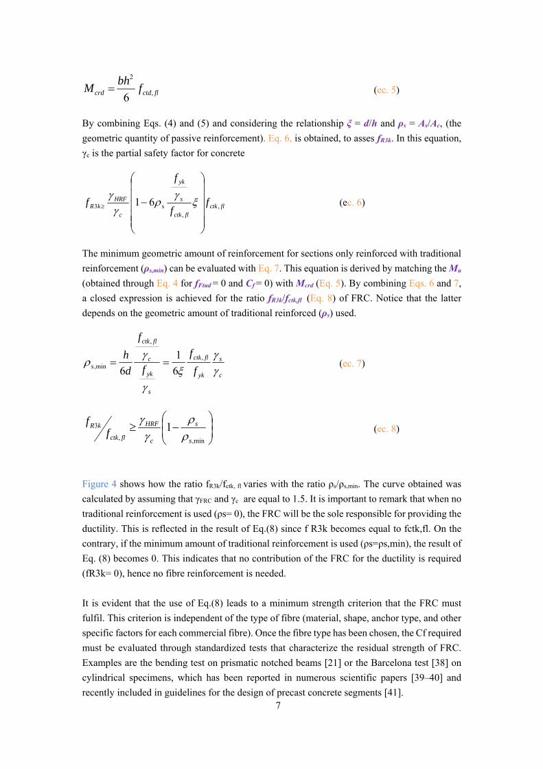
Figure 4 shows how the ratio fR3k/fctk, fl varies with the ratio ρs/ρs,min. The curve obtained was
calculated by assuming that γFRC and γc are equal to 1.5. It is important to remark that when no
traditional reinforcement is used (ρs= 0), the FRC will be the sole responsible for providing the
ductility. This is reflected in the result of Eq.(8) since f R3k becomes equal to fctk,fl. On the
contrary, if the minimum amount of traditional reinforcement is used (ρs=ρs,min), the result of
Eq. (8) becomes 0. This indicates that no contribution of the FRC for the ductility is required
(fR3k= 0), hence no fibre reinforcement is needed.
It is evident that the use of Eq.(8) leads to a minimum strength criterion that the FRC must
fulfil. This criterion is independent of the type of fibre (material, shape, anchor type, and other
specific factors for each commercial fibre). Once the fibre type has been chosen, the Cf required
must be evaluated through standardized tests that characterize the residual strength of FRC.
Examples are the bending test on prismatic notched beams [21] or the Barcelona test [38] on
cylindrical specimens, which has been reported in numerous scientific papers [39–40] and
recently included in guidelines for the design of precast concrete segments [41].
8
Figure 4. fR3,k/fctk,fl ratio as a function of the ρs/ρs,min ratio obtained with Eq. 8. (γc = γFRC = 1.50).
4 REDESIGN OF MONTACADA SHAFT SEGMENTS
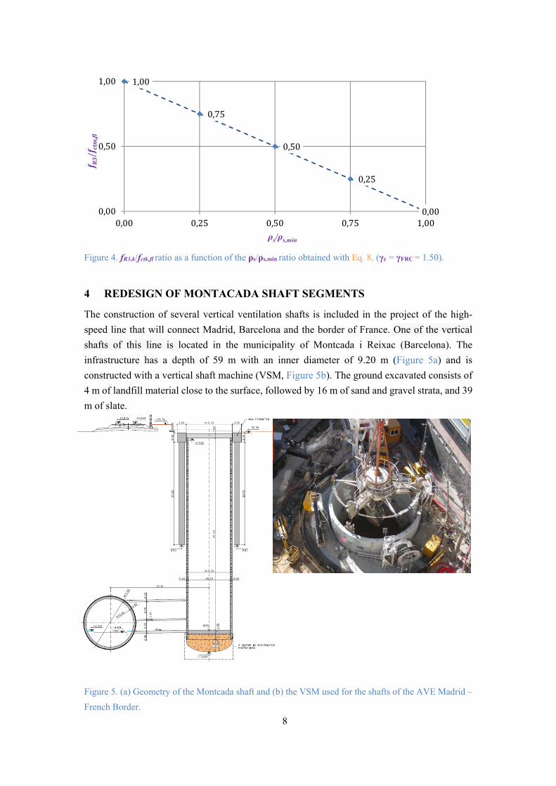
The construction of several vertical ventilation shafts is included in the project of the high-
speed line that will connect Madrid, Barcelona and the border of France. One of the vertical
shafts of this line is located in the municipality of Montcada i Reixac (Barcelona). The
infrastructure has a depth of 59 m with an inner diameter of 9.20 m (Figure 5a) and is
constructed with a vertical shaft machine (VSM, Figure 5b). The ground excavated consists of
4 m of landfill material close to the surface, followed by 16 m of sand and gravel strata, and 39
m of slate.
Figure 5. (a) Geometry of the Montcada shaft and (b) the VSM used for the shafts of the AVE Madrid –
French Border.
1,00
0,75
0,50
0,25
0,000,00
0,50
1,00
0,00 0,25 0,50 0,75 1,00
f R3/f ctm,fl
ρs/ρs,min
9
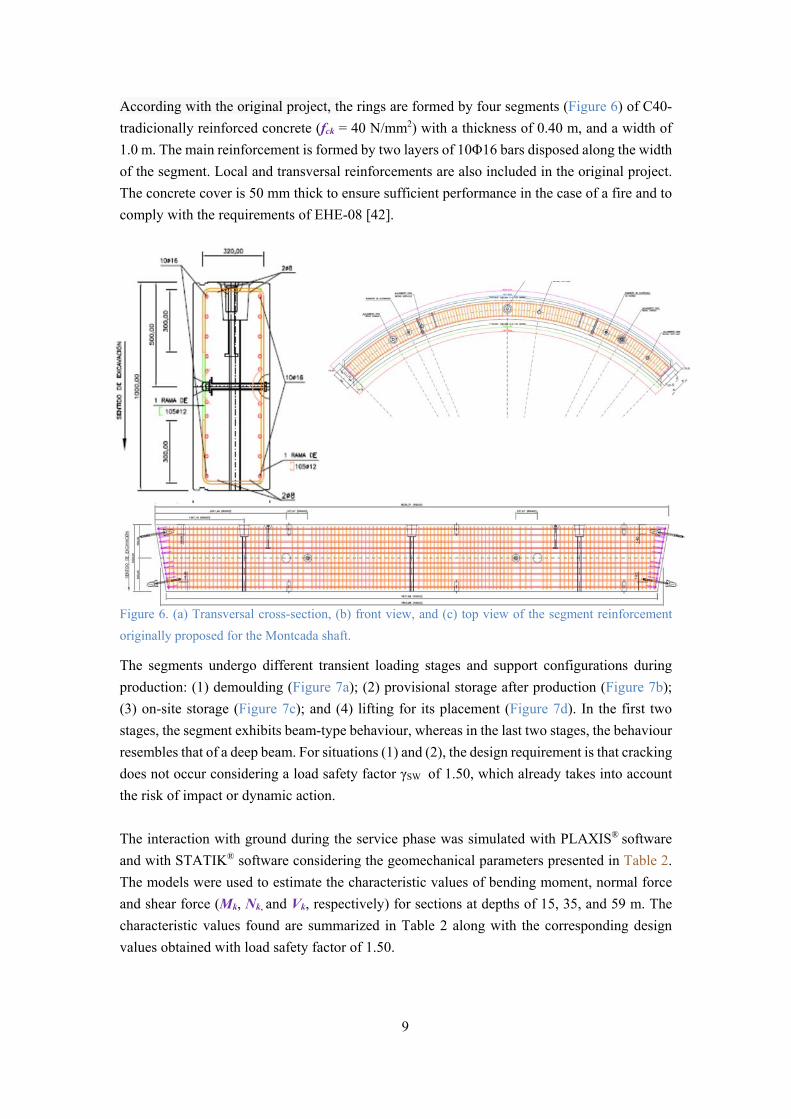
According with the original project, the rings are formed by four segments (Figure 6) of C40-
tradicionally reinforced concrete (fck = 40 N/mm2) with a thickness of 0.40 m, and a width of
1.0 m. The main reinforcement is formed by two layers of 10Φ16 bars disposed along the width
of the segment. Local and transversal reinforcements are also included in the original project.
The concrete cover is 50 mm thick to ensure sufficient performance in the case of a fire and to
comply with the requirements of EHE-08 [42].
Figure 6. (a) Transversal cross-section, (b) front view, and (c) top view of the segment reinforcement
originally proposed for the Montcada shaft.
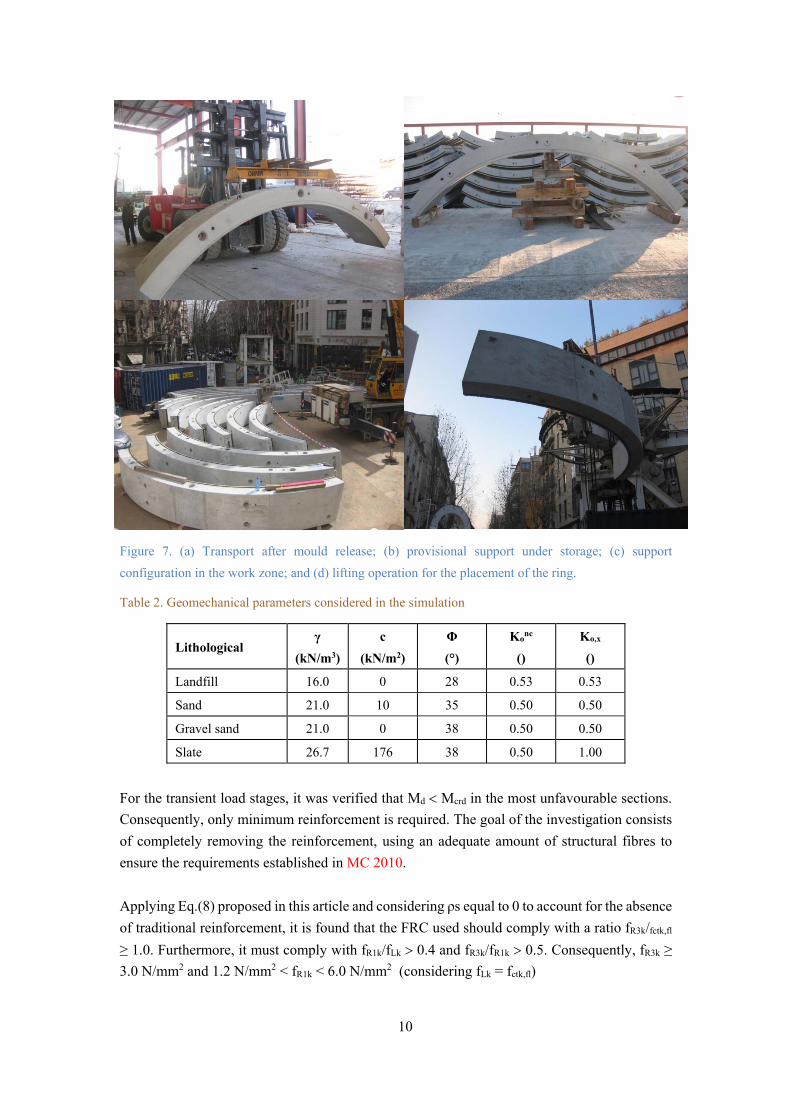
The segments undergo different transient loading stages and support configurations during
production: (1) demoulding (Figure 7a); (2) provisional storage after production (Figure 7b);
(3) on-site storage (Figure 7c); and (4) lifting for its placement (Figure 7d). In the first two
stages, the segment exhibits beam-type behaviour, whereas in the last two stages, the behaviour
resembles that of a deep beam. For situations (1) and (2), the design requirement is that cracking
does not occur considering a load safety factor γSW of 1.50, which already takes into account
the risk of impact or dynamic action.
The interaction with ground during the service phase was simulated with PLAXIS® software
and with STATIK® software considering the geomechanical parameters presented in Table 2.
The models were used to estimate the characteristic values of bending moment, normal force
and shear force (Mk, Nk, and Vk, respectively) for sections at depths of 15, 35, and 59 m. The
characteristic values found are summarized in Table 2 along with the corresponding design
values obtained with load safety factor of 1.50.
10
Figure 7. (a) Transport after mould release; (b) provisional support under storage; (c) support
configuration in the work zone; and (d) lifting operation for the placement of the ring.
Table 2. Geomechanical parameters considered in the simulation
For the transient load stages, it was verified that Md Mcrd in the most unfavourable sections.
Consequently, only minimum reinforcement is required. The goal of the investigation consists
of completely removing the reinforcement, using an adequate amount of structural fibres to
ensure the requirements established in MC 2010.
Applying Eq.(8) proposed in this article and considering ρs equal to 0 to account for the absence
of traditional reinforcement, it is found that the FRC used should comply with a ratio fR3k/fctk,fl
≥ 1.0. Furthermore, it must comply with fR1k/fLk 0.4 and fR3k/fR1k 0.5. Consequently, fR3k ≥
3.0 N/mm2 and 1.2 N/mm2 < fR1k < 6.0 N/mm2 (considering fLk = fctk,fl)
Lithological γ
(kN/m3)
c
(kN/m2)
Φ
(°)
Konc
()
Ko,x
()
Landfill 16.0 0 28 0.53 0.53
Sand 21.0 10 35 0.50 0.50
Gravel sand 21.0 0 38 0.50 0.50
Slate 26.7 176 38 0.50 1.00
11
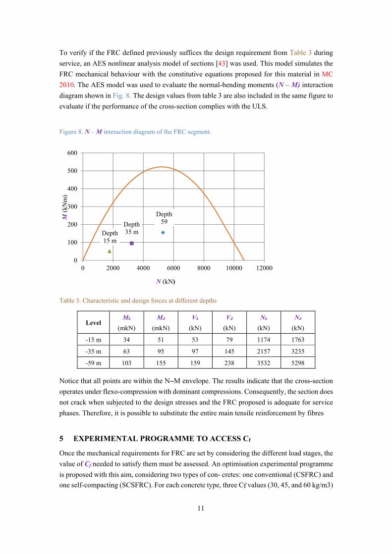
To verify if the FRC defined previously suffices the design requirement from Table 3 during
service, an AES nonlinear analysis model of sections [43] was used. This model simulates the
FRC mechanical behaviour with the constitutive equations proposed for this material in MC
2010. The AES model was used to evaluate the normal-bending moments (N – M) interaction
diagram shown in Fig. 8. The design values from table 3 are also included in the same figure to
evaluate if the performance of the cross-section complies with the ULS.
Figure 8. N – M interaction diagram of the FRC segment.
Table 3. Characteristic and design forces at different depths
Notice that all points are within the N–M envelope. The results indicate that the cross-section
operates under flexo-compression with dominant compressions. Consequently, the section does
not crack when subjected to the design stresses and the FRC proposed is adequate for service
phases. Therefore, it is possible to substitute the entire main tensile reinforcement by fibres
5 EXPERIMENTAL PROGRAMME TO ACCESS Cf
Once the mechanical requirements for FRC are set by considering the different load stages, the
value of Cf needed to satisfy them must be assessed. An optimisation experimental programme
is proposed with this aim, considering two types of con- cretes: one conventional (CSFRC) and
one self-compacting (SCSFRC). For each concrete type, three Cf values (30, 45, and 60 kg/m3)
Depth15 m
Depth35 m
Depth59
0
100
200
300
400
500
600
0 2000 4000 6000 8000 10000 12000
M(k
Nm
)
N (kN)
Level Mk
(mkN)
Md
(mkN)
Vk
(kN)
Vd
(kN)
Nk
(kN)
Nd
(kN)
-15 m 34 51 53 79 1174 1763
-35 m 63 95 97 145 2157 3235
-59 m 103 155 159 238 3532 5298
12
were used to estimate the minimum needed to comply with the performance parameters
obtained in Section 4 (Cf,min).
In total, six concrete mixes were produced with the compositions presented in Table 4. A steel
fibre with hook-shaped anchorage was used. These fibres had a minimum elastic limit of 1000
N/mm2, length of 50 mm ± 1 mm and diameter of 1.0 mm ± 0.1 mm.
In the fresh state, the consistency was characterized with the slump flow test [44] for the CSFRC
and with the flow extent test [45] for the SCSFRC. Moreover, the content of occluded air and
the density were measured using the tests described in [46] and in [47], respectively.
Table 4. Composition of FRCC and FRSCC [in kg/m3]
Mixtures CFRC FRSCC
Sand 0/5 817 1200
Fine aggregate 5/15 404 500
Coarse aggregate 12/20 810 200
Water 156 165
CEM I 52.5 R 312 380
Superplasticizer 2.19 4.56
The results of the fresh state tests are presented in Table 5. The SCSFRC reached flow extents
above the 60 cm established in the [46] as a minimum for self-compacting concrete. It was also
observed that the CSFRC present an occluded air content approximately 2.5 smaller than the
SCSFRC. This may be the consequence of the higher amount and different type of
superplasticizer, as well as, the higher mortar content used in the former to increase the
flowability.
Table 5. Test results on fresh state.
To characterize the mechanical behaviour of each mixture in the hardened state, nine cylindrical
specimens were moulded (Φ150 × 150 in mm) to evaluate the compressive strength fc
according with [48] at 1, 7, and 28 days of age. In addition to that, three prisms (150 × 150 ×
600 in mm) were cast to perform the notched three-point test [28] and evaluate fL and fRi at 28
Series Cone test
(cm)
Flow test
(cm)
Air content
(%)
Density
(kg/m3)
FRCC-30 3 - 1.8 2481
FRCC-45 5 - 2.1 2481
FRCC-60 3 - 2.2 2494
FRSCC-30 - 65 5.4 2394
FRSCC-45 - 65 5.5 2394
FRSCC-60 - 67 7.4 2319
13
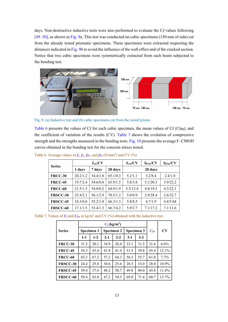
days. Non-destructive inductive tests were also performed to evaluate the Cf values following
[49–50], as shown in Fig. 9a. This test was conducted on cubic specimens (150 mm of side) cut
from the already tested prismatic specimens. These specimens were extracted respecting the
distances indicated in Fig. 9b to avoid the influence of the wall effect and of the cracked section.
Notice that two cubic specimens were symmetrically extracted from each beam subjected to
the bending test.
Fig. 9. (a) Inductive test and (b) cubic specimens cut from the tested prisms
Table 6 presents the values of Cf for each cubic specimen, the mean values of Cf (Cfm), and
the coefficient of variation of the results (CV). Table 7 shows the evolution of compressive
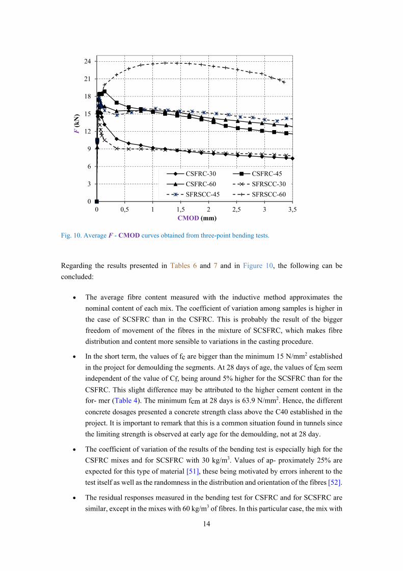
strength and the strengths measured in the bending tests. Fig. 10 presents the average F–CMOD
curves obtained in the bending test for the concrete mixes tested.
Table 6. Average values of fc, fL, fR1, and fR3 (N/mm2) and CV (%)
Series fcm/CV fLm/CV fR1m/CV fR3m/CV
1 days 7 days 28 days 28 days
FRCC-30 20.2/1.2 54.4/1.8 65.1/0.3 5.2/1.1 3.2/8.4 2.4/1.8
FRCC-45 19.7/2.4 54.6/0.8 63.9/1.5 5.8/3.8 5.1/20.3 3.9/22.2
FRCC-60 21.5/1.5 54.8/0.2 64.9/1.9 5.5/12.4 4.8/19.3 4.3/22.1
FRSCC-30 25.4/2.1 56.1/2.9 70.5/1.2 5.0/9.9 2.9/28.4 2.6/32.7
FRSCC-45 18.3/0.8 55.2/1.8 66.3/1.3 5.8/8.5 4.7/1.9 4.8/5.84
FRSCC-60 17.1/1.5 53.4/1.3 66.7/4.2 5.9/2.7 7.1/17.2 7.1/11.6
Table 7. Values of Cf and Cfm in kg/m3 and CV (%) obtained with the inductive test.
Series
Cf (kg/m3)
Cfm CV Specimen 1 Specimen 2 Specimen 3
1-1 1-2 2-1 2-2 3-1 3-2
FRCC-30 31.5 30.1 34.9 28.4 33.1 31.5 31.6 6.6%
FRCC-45 54.3 43.4 41.9 41.4 51.5 39.8 45.4 12.1%
FRCC-60 65.3 67.2 57.2 64.3 56.3 55.7 61.0 7.7%
FRSCC-30 24.4 25.8 30.6 25.6 28.5 33.0 28.0 10.9%
FRSCC-45 39.4 37.6 48.2 50.7 49.8 49.0 45.8 11.4%
FRSCC-60 59.4 63.0 47.2 54.3 69.0 71.4 60.7 13.7%
14
Fig. 10. Average F - CMOD curves obtained from three-point bending tests.
Regarding the results presented in Tables 6 and 7 and in Figure 10, the following can be
concluded:
The average fibre content measured with the inductive method approximates the
nominal content of each mix. The coefficient of variation among samples is higher in
the case of SCSFRC than in the CSFRC. This is probably the result of the bigger
freedom of movement of the fibres in the mixture of SCSFRC, which makes fibre
distribution and content more sensible to variations in the casting procedure.
In the short term, the values of fc are bigger than the minimum 15 N/mm2 established
in the project for demoulding the segments. At 28 days of age, the values of fcm seem
independent of the value of Cf, being around 5% higher for the SCSFRC than for the
CSFRC. This slight difference may be attributed to the higher cement content in the
for- mer (Table 4). The minimum fcm at 28 days is 63.9 N/mm2. Hence, the different
concrete dosages presented a concrete strength class above the C40 established in the
project. It is important to remark that this is a common situation found in tunnels since
the limiting strength is observed at early age for the demoulding, not at 28 day.
The coefficient of variation of the results of the bending test is especially high for the
CSFRC mixes and for SCSFRC with 30 kg/m3. Values of ap- proximately 25% are
expected for this type of material [51], these being motivated by errors inherent to the
test itself as well as the randomness in the distribution and orientation of the fibres [52].
The residual responses measured in the bending test for CSFRC and for SCSFRC are
similar, except in the mixes with 60 kg/m3 of fibres. In this particular case, the mix with
0
3
6
9
12
15
18
21
24
0 0,5 1 1,5 2 2,5 3 3,5
F(k
N)
CMOD (mm)
CSFRC-30 CSFRC-45
CSFRC-60 SFRSCC-30
SFRSCC-45 SFRSCC-60
15
2,32,5
2,7
1.2
4.3
5.7
fR3k = 0.797fR1kR² = 0.006
(FRCC)
fR3k = 1.037fR1kR² = 0.952(FRSCC)
0,0
1,0
2,0
3,0
4,0
5,0
6,0
0,0 1,0 2,0 3,0 4,0 5,0 6,0
f R3k
(N/m
m2 )
fR1k (N/mm2)
2,8
3,4 3,3
1,5
4,6
5,1
fR1k = 0.017Cf + 2.37R² = 0.583
(FRCC)
fR1k = 0.118Cf - 1.59R² = 0.862(FRSCC)
0,0
1,0
2,0
3,0
4,0
5,0
6,0
30 45 60
f R1k
(N/m
m2 )
Cf (kg/m3)
self-compacting concrete presents hardening, whereas the mix with conventional
concrete presents soft- ening with a behaviour close to that of CSFRC-40. This may be
partially attributed to the high scatter in the residual strength of mixes CSFRC- 40 and
SCSFRC-60.
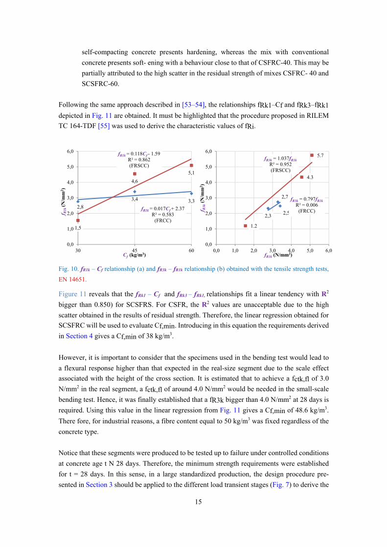
Following the same approach described in [53–54], the relationships fRk1–Cf and fRk3–fRk1
depicted in Fig. 11 are obtained. It must be highlighted that the procedure proposed in RILEM
TC 164-TDF [55] was used to derive the characteristic values of fRi.
Fig. 10. fR1k – Cf relationship (a) and fR3k – fR1k relationship (b) obtained with the tensile strength tests,
EN 14651.
Figure 11 reveals that the fRk1 – Cf and fRk3 – fRk1, relationships fit a linear tendency with R2
bigger than 0.850) for SCSFRS. For CSFR, the R2 values are unacceptable due to the high
scatter obtained in the results of residual strength. Therefore, the linear regression obtained for
SCSFRC will be used to evaluate Cf,min. Introducing in this equation the requirements derived
in Section 4 gives a Cf,min of 38 kg/m3.
However, it is important to consider that the specimens used in the bending test would lead to
a flexural response higher than that expected in the real-size segment due to the scale effect
associated with the height of the cross section. It is estimated that to achieve a fctk,fl of 3.0
N/mm2 in the real segment, a fctk,fl of around 4.0 N/mm2 would be needed in the small-scale
bending test. Hence, it was finally established that a fR3k bigger than 4.0 N/mm2 at 28 days is
required. Using this value in the linear regression from Fig. 11 gives a Cf,min of 48.6 kg/m3.
There fore, for industrial reasons, a fibre content equal to 50 kg/m3 was fixed regardless of the
concrete type.
Notice that these segments were produced to be tested up to failure under controlled conditions
at concrete age t N 28 days. Therefore, the minimum strength requirements were established
for t = 28 days. In this sense, in a large standardized production, the design procedure pre-
sented in Section 3 should be applied to the different load transient stages (Fig. 7) to derive the
16
ratios fR3k(t*)/fLOPk(t*) at a given time. Posteriorly, the suitability of the material can be
assessed obtaining the fR3k–t curves from the 3-point bending test on notched beams as
proposed in [56].
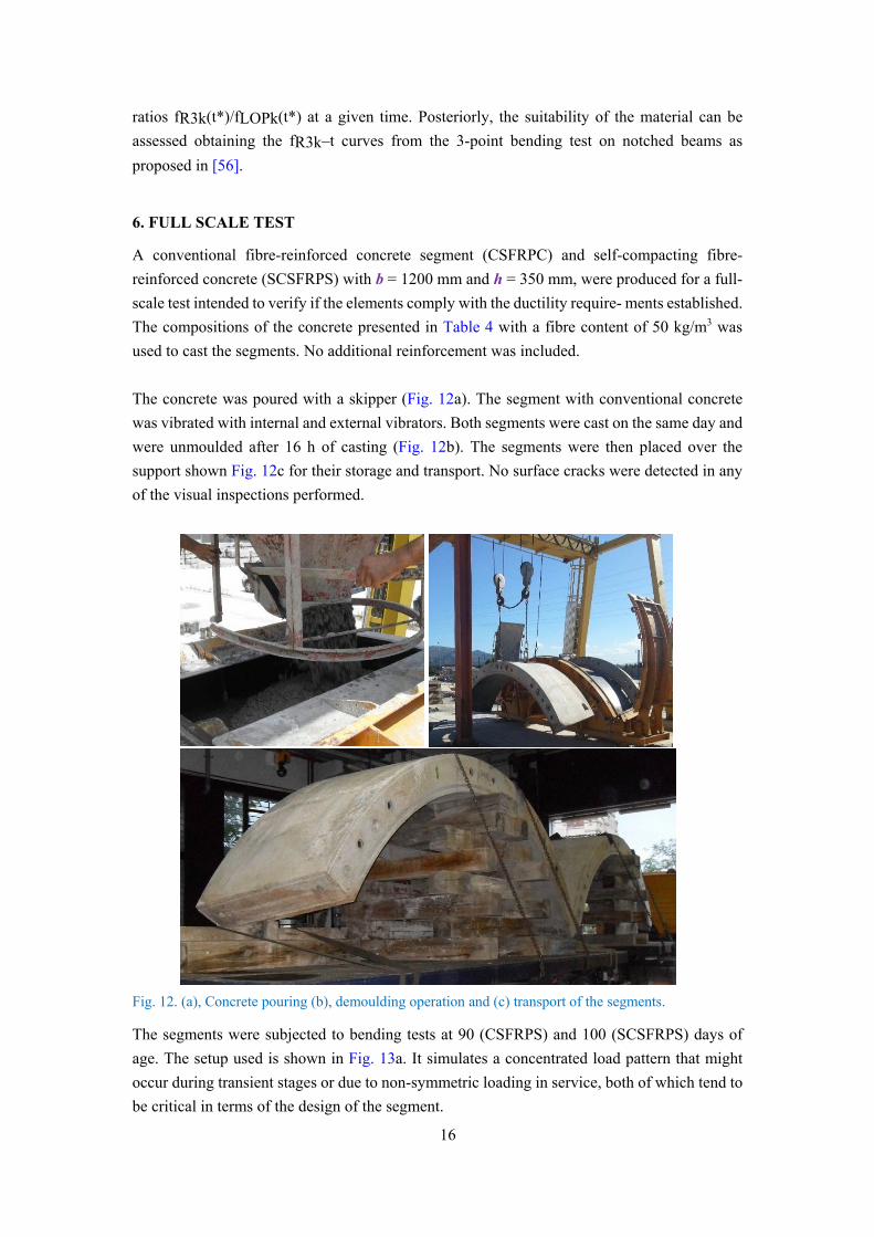
6. FULL SCALE TEST
A conventional fibre-reinforced concrete segment (CSFRPC) and self-compacting fibre-
reinforced concrete (SCSFRPS) with b = 1200 mm and h = 350 mm, were produced for a full-
scale test intended to verify if the elements comply with the ductility require- ments established.
The compositions of the concrete presented in Table 4 with a fibre content of 50 kg/m3 was
used to cast the segments. No additional reinforcement was included.
The concrete was poured with a skipper (Fig. 12a). The segment with conventional concrete
was vibrated with internal and external vibrators. Both segments were cast on the same day and
were unmoulded after 16 h of casting (Fig. 12b). The segments were then placed over the
support shown Fig. 12c for their storage and transport. No surface cracks were detected in any
of the visual inspections performed.
Fig. 12. (a), Concrete pouring (b), demoulding operation and (c) transport of the segments.
The segments were subjected to bending tests at 90 (CSFRPS) and 100 (SCSFRPS) days of
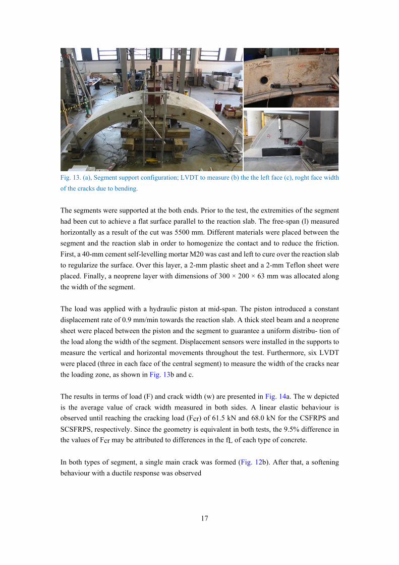
age. The setup used is shown in Fig. 13a. It simulates a concentrated load pattern that might
occur during transient stages or due to non-symmetric loading in service, both of which tend to
be critical in terms of the design of the segment.
17
Fig. 13. (a), Segment support configuration; LVDT to measure (b) the the left face (c), roght face width
of the cracks due to bending.
The segments were supported at the both ends. Prior to the test, the extremities of the segment
had been cut to achieve a flat surface parallel to the reaction slab. The free-span (l) measured
horizontally as a result of the cut was 5500 mm. Different materials were placed between the
segment and the reaction slab in order to homogenize the contact and to reduce the friction.
First, a 40-mm cement self-levelling mortar M20 was cast and left to cure over the reaction slab
to regularize the surface. Over this layer, a 2-mm plastic sheet and a 2-mm Teflon sheet were
placed. Finally, a neoprene layer with dimensions of 300 × 200 × 63 mm was allocated along
the width of the segment.
The load was applied with a hydraulic piston at mid-span. The piston introduced a constant
displacement rate of 0.9 mm/min towards the reaction slab. A thick steel beam and a neoprene
sheet were placed between the piston and the segment to guarantee a uniform distribu- tion of
the load along the width of the segment. Displacement sensors were installed in the supports to
measure the vertical and horizontal movements throughout the test. Furthermore, six LVDT
were placed (three in each face of the central segment) to measure the width of the cracks near
the loading zone, as shown in Fig. 13b and c.
The results in terms of load (F) and crack width (w) are presented in Fig. 14a. The w depicted
is the average value of crack width measured in both sides. A linear elastic behaviour is
observed until reaching the cracking load (Fcr) of 61.5 kN and 68.0 kN for the CSFRPS and
SCSFRPS, respectively. Since the geometry is equivalent in both tests, the 9.5% difference in
the values of Fcr may be attributed to differences in the fL of each type of concrete.
In both types of segment, a single main crack was formed (Fig. 12b). After that, a softening
behaviour with a ductile response was observed
18
0
10
20
30
40
50
60
70
0 1 2 3 4
F(K
N)
w (mm)
FRCCSFRSCCS
Fig. 14. a) Load (F) – crack width (w) curves and b) detail values obtained in the full-scale tests.
The results presented in Figure 14b also show that up to values of w close to 1.5 mm, the
SCSFRPS presents a load that is, at most, 18.3% higher compared with that of CSFRPS. For w
bigger than 1.5 mm, the response of both segments was equivalent in terms of F, thus
confirming the general trend observed in the small scale experimental programme from Section
5.
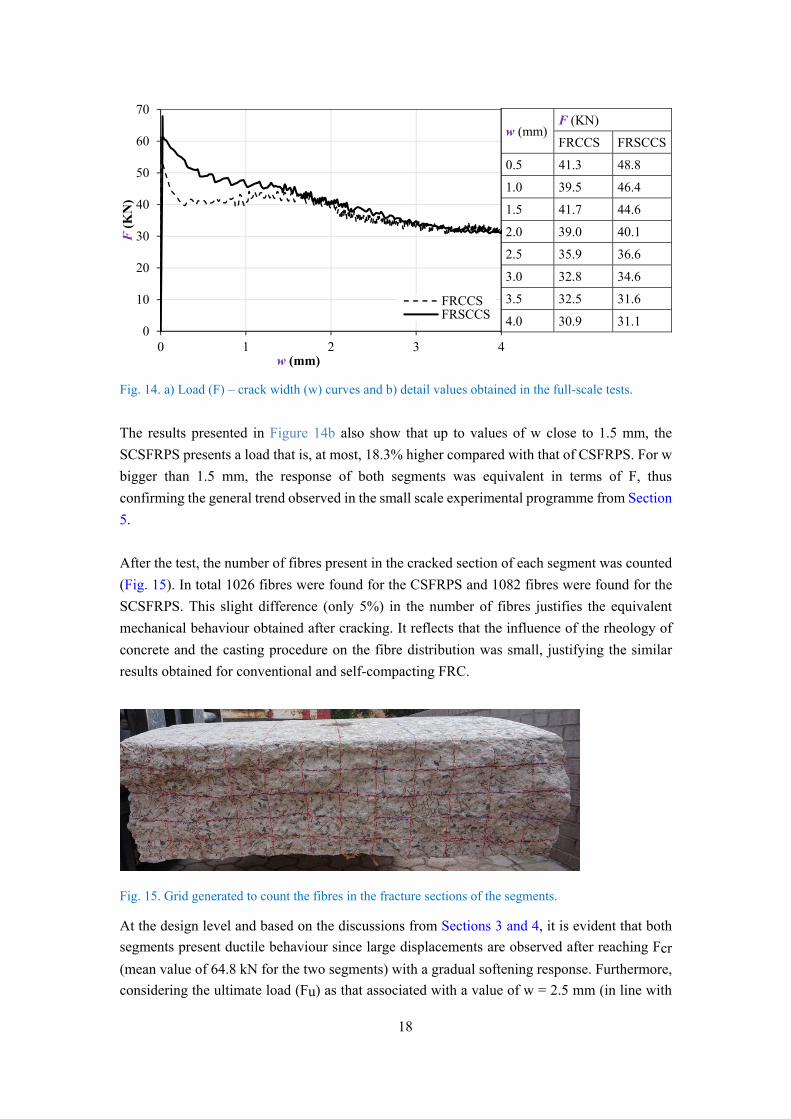
After the test, the number of fibres present in the cracked section of each segment was counted
(Fig. 15). In total 1026 fibres were found for the CSFRPS and 1082 fibres were found for the
SCSFRPS. This slight difference (only 5%) in the number of fibres justifies the equivalent
mechanical behaviour obtained after cracking. It reflects that the influence of the rheology of
concrete and the casting procedure on the fibre distribution was small, justifying the similar
results obtained for conventional and self-compacting FRC.
Fig. 15. Grid generated to count the fibres in the fracture sections of the segments.
At the design level and based on the discussions from Sections 3 and 4, it is evident that both
segments present ductile behaviour since large displacements are observed after reaching Fcr
(mean value of 64.8 kN for the two segments) with a gradual softening response. Furthermore,
considering the ultimate load (Fu) as that associated with a value of w = 2.5 mm (in line with
w (mm)F (KN)
FRCCS FRSCCS
0.5 41.3 48.8
1.0 39.5 46.4
1.5 41.7 44.6
2.0 39.0 40.1
2.5 35.9 36.6
3.0 32.8 34.6
3.5 32.5 31.6
4.0 30.9 31.1
19
the value of fR3 accepted in MC 2010 for the design in ULS), the results of Fig. 14b indicate
that Fu reaches values of 35.9 kN for the CSFRPS and 36.6 kN for the SCSFRPS, with a mean
value of 36.3 kN.
In this regard, the design performed in Section 4 is valid because Eq. (8) is presented with
characteristic strength values, whereas the tests results must be evaluated with mean values.
Thus, the fctk,fl of 4.0 N/mm2 considered for the C60 leads to Mcrk = 98 kNm. The bending
moment associated with the self-weight is Mpp = q · l 2/8 = 45 kNm (q = 10.5 kN/m) The
moment associated with force F* that would generate cracking under the design conditions is
MF*,cr = Mcrk − Mpp = 53 kNm. Therefore, the cracking load under the setup configuration
used could be calculated as F*cr = 4MF*,cr/l = 38.5 kN and should be compared with Fu =
36.3 kNm to be consistent with the proposed design strategy and to evaluate the suitability of
Eq. (8)
It is observed that F*cr is 5.7% bigger than Fu. Therefore, the presented design would be
slightly on the unsafe side. However, it is important to remark that the fct,fl estimated from
these full-scale tests is 5.1 N/mm2, which is 27.5% bigger than the 4.0 N/mm2 considered in
the design for C60 concrete. Consequently, given the increment of fct,fl, the cracking risk is
lower as well as the likelihood of reaching an ULS.
Considering the hypotheses and design criterion presented in Section 3 and the experimental
campaign performed on the material and the segments, it was decided to modify the project
reinforcement presented in Fig. 11. In the new design, part of the segments were rein forced
solely with 50 kg/m3 of the structural steel fibres
7 CONCLUSIONS
This study addressed the design and the characterization of fibre- reinforced concrete segments
to be used in the vertical shafts constructed with VSM. This type of structural element primarily
works under compression during the service phase and the only tensile stresses that appear in
the segments are produced during the transitional phases and have a low cracking risk.
Therefore, the main bending reinforce- ment usually responds to minimum quantities of
traditional reinforce- ment (ρs,min). The replacement of this reinforcement by an adequate
quantity of structural fibres (Cf) is a possibility that may bring technical as well as economic
advantages. The following conclusions are derived from this study.
The fR3/fL ratio is linearly related with the ρs/ρs,min ratio, which also takes into
account the partial safety coefficients γc and γFRC through the analytical equation (Eq.
(8)) proposed here. This equation helps to establish the minimum FRC requirements
for hybrid sections (fibres + bars) subjected to reduced stresses (lower than the cracking
moment Mcr). This expression represents an important contribution for the design of
20
FRC elements and has been proposed in the docu- ment by fib committee 1.4.1.
“Tunnels in fibre reinforced concrete”.
Based on the experimental campaign and the application of Eq.(8) for the redesign of
the segment from the Montcada shaft (Barcelona), it was observed that the value of Cf
that allowed the complete replace- ment of the reinforcement proposed in the initial
project (minimum by mechanic criteria) is 50 kg/m3.
The mechanical behaviours of the CSFRPS and the SCSFRPS cast with 50 kg/m3 of
fibres in the full-scale bending tests were both ductile. Furthermore, an almost
equivalent response was obtained in both segments for cracking when w ≥ 1.5 mm,
which shows the reduced influence of rheology in fresh-state concrete on the behaviour
in ULS. In this regard, the number of fibres in the failure sections differs by less than
5% for each segment, thus justifying the similar results.
Acknowledgements
The authors would like to thank the Ministry of Science and Innovation for the economic
support received through Research Project BIA2010-17478: Construction processes by means
of fibre reinforced concretes and BIA2013-49106-C2-1-R. The first author would like to
acknowledge the scholarship received from the China Scholarship Council and the support from
the Taiyuan University of Technology.
References
[1] fib Bulletins 65–66, Model Code 2010 Final Draft, fédération internationale du béton
(fib), Lausanne, Switzerland, 2010.
[2] A. Caratelli, A. Meda, Z. Rinaldi, P. Romualdi, Structural behaviour of precast tunnel
segments in fibre reinforced concrete, Tunn. Undergr. Space Technol. 26 (2) (2011) 284–
291.
[3] J. Poh, K.H. Tan, G.L. Peterson, D. Wenm, Structural Testing of Steel Fibre Reinforced
Concrete (SFRC) Tunnel Lining Segments in Singapore, WTC, Budapest, Hungary,
2009.
[4] G.P. Lee, G.J. Bae, D.Y. Moon, T.S. Kang, S.H. Chang, Evaluation of steel fibre
reinforcement effect in segment lining by full scale bending test, J. Korean Tunn.
Undergr. Sp Assoc. 15 (3) (2013) 215–223.
[5] R. Gettu, B. Barragán, T. García, G. Ramos, C. Fernández, R. Oliver, Steel fibre
reinforced concrete for the Barcelona metro line 9 tunnel lining, The 6th RILEM
Symposium on FRC, Varenna, Italy 2004, pp. 141–156 (September 20–22).
21
[6] J. Beno, M. Hilar, Steel fibre reinforced concrete for tunnel lining — verification by
extensive laboratory testing and numerical modelling, Acta Polytechnia 53 (4) (2013)
329–337 (Czech Technical University, Prague).
[7] H. Mashimoto, N. Isago, T. Kitani, Numerical approach design of tunnel concrete lin-
ing considering effect of fibre reinforcements, Tunnelling and Underground Space
Technology. Underground Space for Sustainable Urban Development. Proceedings of
the 30th ITA-AITES WTC 2004, 2004 (22–27 May, Singapore).
[8] S. Abbas, A. Soliman, M. Nehdi, Structural behaviour of ultra-high performance fibre
reinforced concrete tunnel lining segments, FRC 2014 Joint ACI–fib International
Workshop. Fibre Reinforced Concrete Applications, 2014 (24–25 July, Montreal,
Canada).
[9] M. Blazejowsky, Flexural Behaviour of Steel Fibre Reinforced Concrete Tunnel
Linings(Electronic Thesis and Dissertation Repository) University of Western Ontario,
Canada, 2012.
[10] G.A. Plizzari, G. Tiberti, Steel fibres as reinforcement for precast tunnel segments, Tunn.
Undergr. Sp. Technol. 21 (3–4) (2006) 438–439.
[11] M. di Prisco, G. Plizzari, L. Vandewalle, Fibre reinforced concrete: new design
perspectives, Mater. Struct. 42 (9) (2009) 1261–1281.
[12] J. Walraven, High performance fibre reinforced concrete: progress in knowledge and
design codes, Mater. Struct. 42 (9) (2009) 1247–1260.
[13] A. de la Fuente, A. Blanco, P. Pujadas, A. Aguado, Experiences in Barcelona with the
use of fibres in segmental linings, Tunn. Undergr. Space Technol. 27 (1) (2011) 60–71.
[14] W. Angerer, M. Chappell, Design of steel fibre reinforced segmental lining for the gold
coast desalination tunnels, 13th Australian Tunneling Conference 2008,
[15] C. Molins, O. Arnau, Experimental and analytical study of the structural response of
segmental tunnel linings based on an in situ loading test. Part 1: test configuration and
execution, Tunn. Undergr. Space Technol. 26 (6) (2011) 764–777.
[16] W.Q. Ding, Q.Z. Yue, G.L. Tham, H.H. Zhu, C.F. Lee, T. Hashimoto, Analysis of shield
tunnel, Int. J. Numer. Anal. Methods Geomech. 58 (2004) 57–91.
[17] R.G.A. deWaal, Steel Fibre Reinforced Tunnel Segments (ISBN90-407-1965-9) Delft
University of Technology, The Netherlands, 1999.
[18] A.G. Kooiman, Modelling Steel Fibre Reinforced Concrete for Structural Design (Ph.D.
thesis) Delft University of Technology, The Netherlands, 2000.
[19] A. Caratelli, A. Meda, Z. Rinaldi, Design according to MC2010 of fibre-reinforced con-
crete tunnel in Monte Lirio, Panama. Struct. Conc. 13 (3) (2012) 166–173.
22
[20] M. Bakhshi, V. Nasri, Structural design of segmental tunnellinings,The 3rd International
Conference on Computational Methods in Tunnelling and Subsurface Engineering, Ruhr
University Bochum, Germany, 2013 (17–19 April).
[21] M. Bakhshi, V. Nasri, Guidelines and methods on segmental tunnel lining analysis and
design — review and best practice recommendation, Proceedings of the World Tunnel
Congress 2014, 2014 (May 9–15). (Iguassu Falls, Brazil).
[22] B. Chiaia, A.F. Fantilli, P. Vallini, Combining fibre-reinforced concrete with traditional
reinforcement in tunnel linings, Eng. Struct. 31 (7) (2009) 1600–1606.
[23] B. Chiaia, A.P. Fantilli, P. Vallini, Evaluation of minimum reinforcement ratio in FRC
members and application to tunnel linings, Mater. Struct. 42 (3) (2009) 339–351.
[24] O. Arnau, C. Molins, Experimental and analytical study of the structural response of
segmental tunnel linings based on an in situ loading test. Part 2: numerical simulation,
Tunn. Undergr. Space Technol. 26 (6) (2011) 778–788.
[25] P.E. Roelfstra, F.H. Wittmann, Numerical method to link strains oftening with failure of
concrete, in: F.H. Wittmann (Ed.), Fracture Toughness and Fracture Energy of Concrete,
Elsevier Science 1986, pp. 163–175.
[26] A.H.J.M. Vervuurt, C. Van del Veen, F.B.J. Gijsbers, F.B.I. Den Uijl, Numerical simula-
tions of tests on a segmented tunnel lining, Procedings of the DIANA World Conference
2002, pp. 429–437 (Tokyo).
[27] T. Kasper, G. Meshke, A 3D finite element simulation model for TBM tunnelling in soft
ground, Int. J. Numer. Anal. Methods Geomech. 1 (28) (2004) 1441–1460.
[28] EN 14651, Test method for metallic fibre concrete, Measuring the Flexural Tensile
Strength (Limit of Proportionality (LOP), Residual), 2005.
[29] F. Levi, On minimum reinforcement in concrete structures, ASCE J. Struct. Eng. 111(12)
(1985) 791–2796.
[30] L. Liao, A. de la Fuente, S. Cavalaro, A. Aguado, Design of FRC tunnel segments
considering the ductility requirements of the MC 2010, Tunn. Undergr. Space Technol.
47 (3) (2015) 200–210.
[31] O. Hemmy, Brite Euram Program on Steel Fibre Concrete, Subtask: Splitting of SFRC
Induced by Local Forces: Investigation of Tunnel Segments Without Curvature,
University of Braunschweig, Germany, 2001.
[32] R. Burguers, Non-linear FEM Modelling of Steel Fibre Reinforced Concrete for the
Analysis of Tunnel Segments in the Thrust Jack Phase (Mater thesis) Delft University of
Technology, The Netherlands, 2006.
[33] R. Burgers, J.C. Walraven, G.A. Plizzari, G. Tiberti, Structural behaviour of SFRC
tunnel segments during TBM operations, Underground Space the 4th Dimension of
23
Metropolises: Proceedings of the World Tunnel Congress 2007 and 33rd ITA/AITES
Annual General Assembly, 2007 (London, England).
[34] G. Tiberti, G. Plizzari, Structural behaviour of precast tunnel segments under TBM thrust
actions, World Tunnelling Congress: Tunnels for a Better Life, WTC, Foz do Iguaçu,
Brazil, 2014 (9–15 May, 2014).
[35] R. Breitenbücher, G. Meschke, F. Song, M. Hofman, Y. Zhan, Experimental and nu-
merical study on the load-bearing behaviour of steel fibre reinforced concrete for precast
tunnel lining segments under concentrated loads, FRC 2014 Joint ACI–fib In- ternational
Workshop. Fibre Reinforced Concrete Applications, 2014 (24–25 July). (Montreal,
Canada).
[36] M. Bakhshi, V. Nasri, Developments in design for fibre reinforced concrete tunnel
segments, FRC 2014 Joint ACI–fib International Workshop. Fibre Reinforced Con- crete
Applications, 2014 (24–25 July). (Montreal, Canada).
[37] L. Liao, A. de la Fuente, S. Cavalaro, A. Aguado, G. Carbonari, Experimental and ana-
lytical study of concrete blocks subjected to concentrated loads with an application to
TBM-constructed tunnels, Tunn. Undergr. Space Technol. 49 (1) (2015) 295–306.
[38] UNE 83515, Fibre reinforced concrete, Determination of Cracking Strength, Ductility
and Residual Tensile Strength. Barcelona Test, Spanish Association for Standardiza- tion
and Certification, AENOR, 2010.
[39] S. Carmona, A. Aguado, C. Molins, Generalization of the Barcelona test for the tough-
ness control of FRC, Mater. Struct. 45 (7) (2012) 1053–1069.
[40] P. Pujadas, A. Blanco, S. Cavalaro, A. de la Fuente, A. Aguado, New analytical model
to generalize the Barcelona test using axial displacement, J. Civ. Eng. Manag. 19 (2)
(2013) 259–271.
[41] ITATECH Activity Group Support, ITATECH design guidance for precast fibre rein-
forced concrete segments(July) Draft Report, 2015.
[42] EHE-08: Spanish Structural Concrete Standard. Annex 14: Recommendations for the
Use of Fibre Reinforced Concrete.
[43] A. de la Fuente, A. Aguado, C. Molins, J. Armengou, Numerical model for the analysis
up to failure of precast concrete sections, Comput. Struct. (2012) 106–107 (pp.: 105–14).
[44] EN 12350-2, Testing Fresh Concrete: Slump-test, 2009.
[45] EN 12350-8, Testing fresh concrete, Self-compacting Concrete: Slump-flow Test, 2010.
[46] EN 12350-7, Testing fresh concrete: Air content, Press. Meth. (2009).
[47] EN 12350-6, Testing Fresh Concrete: Density, 2009.
[48] EN 12390-3, Testing Hardened Concrete: Compressive Strength of Test Specimens,
2009.
24
[49] J. Torrents, A. Blanco, P. Pujadas, A. Aguado, P. Juan-Garcia, M. Sanchez-Moragues,
[50] S.H.P. Cavalaro, R. Lopez, J. M. Torrents, A. Aguado, Assessment of fibre content and
3D profile in cylindrical SFRC specimens, Mater. Struct. (2014), http://dx.doi.org/
10.1617/s11527-014-0521-2.
[51] A. Blanco, P. Pujadas, A. de la Fuente, S. Cavalaro, A. Aguado, Application of
constitutive models in European codes to RC–FRC, Constr. Build. Mater. 40 (2013) 246–
259.
[52] A. Blanco, P. Pujadas, A. de la Fuente, S. Cavalaro, A. Aguado, Assessment of the fibre
orientation factor in SFRC slabs, Compos. Part B 68 (2) (2015) 343–354 (2015).
[53] J.A.O. Barros, V.M.C.F. Cunha, A.F. Ribeiro, J.A.B. Antunes, Post-cracking behaviour
of steel fibre reinforced concrete, Mater. Struct. 38 (1) (2005) 47–56.
[54] A. de la Fuente, R.C. Escariz, A.D. de Figueiredo, A. Aguado, Design of macro-synthetic
fibre reinforced concrete, Constr. Build. Mater. 43 (2013) 523–532 (2013).
[55] RILEM TC 162-TDF, Test and design methods for steel fibre reinforced concrete. σ–ε
design method: final recommendation, RILEM Materials and Structures 36 (262) (2003)
560–567.
[56] A. Meda, Z. Rinaldi, Steel fibers reinforcement for precast lining in tunnels with different
diameters, FRC 2014 Joint ACI–fib International Workshop. Fibre Reinforced Concrete
Applications 2014, pp. 522–531 (24–25 July). (Montreal, Canada).