Embed Size (px)
Citation preview

Designing the Modules
中国科学技术大学软件学院孟宁
2010 年 11 月

Contents
6.1 Design Methodology6.2 Design Principles
6.3 OO Design
6.4 Representing OO Designs in the UML
6.5 OO Design Patterns
6.6 Other Design Considerations
6.7 OO Measurement
6.8 Design Documentation

6.1 Design MethodologyRefactoring
♦ Design decisions are periodically revisited and revised♦ Refactoring♦ Objective: to simplify complicated solutions or to
optimize the design

6.2 Design Principles
♦ Design principles are guidelines for decomposing a system’s required functionality and behavior into modules
♦ The principles identify the criteria– for decomposing a system – deciding what information to provide (and what to conceal) in the
resulting modules
♦ Six dominant principles:– Modularity– Interfaces– Information hiding– Incremental development– Abstraction– Generality

6.2 Design PrinciplesModularity
♦ Modularity is the principle of keeping separate the various unrelated aspects of a system, so that each aspect can be studied in isolation (also called separation of concerns)
♦ If the principle is applied well, each resulting module will have a single purpose and will be relatively independent of the others– each module will be easy to understand and develop– easier to locate faults (because there are fewer suspect modules
per fault) – Easier to change the system (because a change to one module
affects relatively few other modules♦ To determine how well a design separates concerns, we use two
concepts that measure module independence: coupling and cohesion

6.2 Design PrinciplesCoupling
♦ Two modules are tightly coupled when they depend a great deal on each other
♦ Loosely coupled modules have some dependence, but their interconnections are weak
♦ Uncoupled modules have no interconnections at all; they are completely unrelated
Tightly coupled -many dependencies
Loosely coupled -some dependencies
Uncoupled -no dependencies

6.2 Design PrinciplesCoupling (continued)
♦ There are many ways that modules can be dependent on each other:– The references made from one module to another
– The amount of data passed from one module to another
– The amount of control that one module has over the other
♦ Coupling can be measured along a spectrum of dependence

6.2 Design Principles Coupling: Types of Coupling
♦ Content coupling
♦ Common coupling
♦ Control coupling
♦ Stamp coupling
♦ Data coupling
TIGHT COUPLING
LOOSE COUPLING
LOW COUPLING
Content coupling
Common coupling
Control coupling
Stamp coupling
Data coupling
Uncoupled
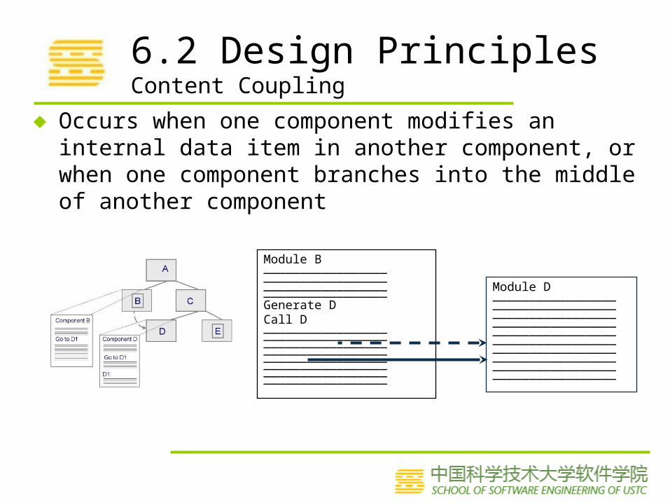
6.2 Design Principles Content Coupling
♦ Occurs when one component modifies an internal data item in another component, or when one component branches into the middle of another component
Module B__________________________________ __________________________________Generate DCall D___________________________________________________ ____________________________________________________________________ _________________
Module D__________________________________ _____________________________________________________________________________________ ___________________________________________________

6.2 Design Principles Common Coupling
♦ Making a change to the common data means tracing back to all components that access those data to evaluate the effect of the change

6.2 Design Principles Control Coupling
♦ When one module passes parameters or a return code to control the behavior of another module
♦ It is impossible for the controlled module to function without some direction from the controlling module
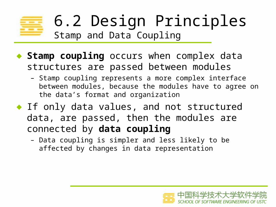
6.2 Design Principles Stamp and Data Coupling
♦ Stamp coupling occurs when complex data structures are passed between modules– Stamp coupling represents a more complex interface between modules,
because the modules have to agree on the data’s format and organization
♦ If only data values, and not structured data, are passed, then the modules are connected by data coupling– Data coupling is simpler and less likely to be affected by changes in
data representation

6.2 Design Principles Cohesion
♦ Cohesion refers to the dependence within and among a module’s internal elements (e.g., data, functions, internal modules)
LOW COHESION
HIGH COHESION
Coincidental
Logical
Temporal
Procedural
Communicational
Functional
Informational
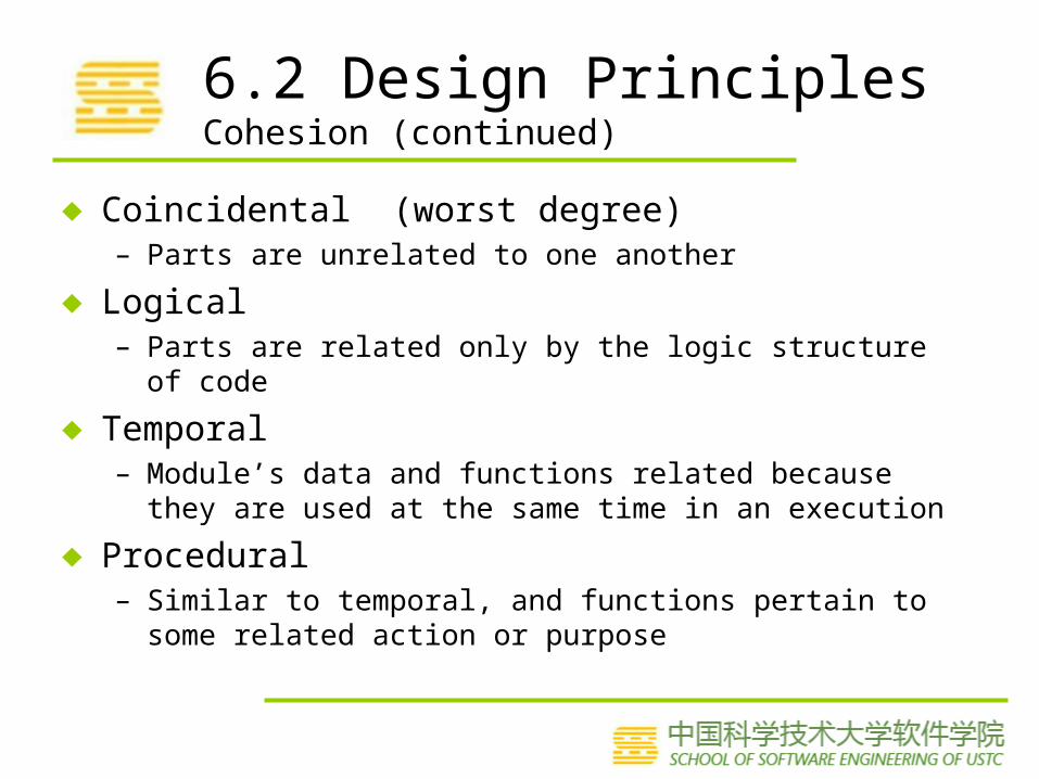
6.2 Design Principles Cohesion (continued)
♦ Coincidental (worst degree)– Parts are unrelated to one another
♦ Logical– Parts are related only by the logic structure of code
♦ Temporal– Module’s data and functions related because they are used at
the same time in an execution
♦ Procedural– Similar to temporal, and functions pertain to some related action
or purpose

6.2 Design Principles Cohesion (continued)
♦ Communication – Operates on the same data set
♦ Functional (ideal degree)– All elements essential to a single function are contained in one module,
and all of the elements are essential to the performance of the function
♦ Informational– Adaption of functional cohesion to data abstraction and object-
based design

6.2 Design Principles Interfaces
♦ An interface defines what services the software unit provides to the rest of the system, and how other units can access those services– For example, the interface to an object is the collection of the object’s
public operations and the operations’ signatures, which specify each operation’s name, parameters, and possible return values
♦ An interface must also define what the unit requires, in terms of services or assumptions, for it to work correctly
♦ A software unit’s interface describes what the unit requires of its environment, as well as what it provides to its environment

6.2 Design Principles Interfaces (continued)
♦ A software unit may have several interfaces that make different demands on its environment or that offer different levels of service
Data_________________________________ _________________
Operation 1 ____________________________________________________________________
Operation 2__________________________________ __________________________________
Module
Interface A
Operation 1 ()Operation 2 ()Operation 4 ()
Interface B
Operation 2 ()
Operation 3 ()
Operation 3____________________________________________________________________
Operation 4____________________________________________________________________

6.2 Design Principles Interfaces (continued)
♦ The specification of a software unit’s interface describes the externally visible properties of the software unit
♦ An interface specification should communicate to other system developers everything that they need to know to use our software unit correctly– Purpose– Preconditions (assumptions)– Protocols– Postconditions (visible effects)– Quality attributes

6.2 Design Principles Information Hiding
♦ Information hiding is distinguished by its guidance for decomposing a system: – Each software unit encapsulates a separate design decision that could
be changed in the future – Then the interfaces and interface specifications are used to describe
each software unit in terms of its externally visible properties
♦ Using this principle, modules may exhibit different kinds of cohesion– A module that hides a data representation may be informationally
cohesive– A module that hides an algorithm may be functionally cohesive
♦ A big advantage of information hiding is that the resulting software units are loosely coupled

6.2 Design Principles Incremental Development
♦ Given a design consisting of software units and their interfaces, we can use the information about the units’ dependencies to devise an incremental schedule of development
♦ Start by mapping out the units’ uses relation– relates each software unit to the other software units
on which it depends
♦ Uses graphs can help to identify progressively larger subsets of our system that we can implement and test incrementally

6.2 Design Principles Incremental Development (continued)
♦ Uses graphs for two designs– Fan-in refers to the number of units that use a
particular software unit– Fan-out refers to the number of unts used by
particular software unit

6.2 Design Principles Incremental Development (continued)
♦ We can try to break a cycle in the uses graph using a technique called sandwiching– One of the cycle’s units is decomposed into two units,
such that one of the new units has no dependencies– Sandwiching can be applied more than once, to break
either mutual dependencies in tightly coupled units or long dependency chains
(a) (b) (c)

6.2 Design Principles Abstraction
♦ An abstraction is a model or representation that omits some details so that it can focus on other details
♦ The definition is vague about which details are left out of a model, because different abstractions, built for different purposes, omit different kinds of details

6.2 Design Principles Generality
♦ Generality is the design principle that makes a software unit as universally applicable as possible, to increase the chance that it will be useful in some future system
♦ We make a unit more general by increasing the number of contexts in which can it be used. There are several ways of doing this:– Parameterizing context-specific information– Removing preconditions– Simplifying postconditions
6.2 Design Principles Generality (continued)
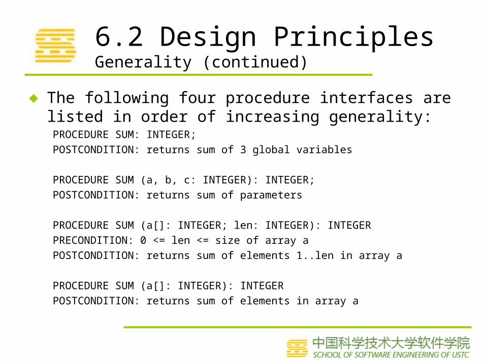
♦ The following four procedure interfaces are listed in order of increasing generality:PROCEDURE SUM: INTEGER;
POSTCONDITION: returns sum of 3 global variables
PROCEDURE SUM (a, b, c: INTEGER): INTEGER;
POSTCONDITION: returns sum of parameters
PROCEDURE SUM (a[]: INTEGER; len: INTEGER): INTEGER
PRECONDITION: 0 <= len <= size of array a
POSTCONDITION: returns sum of elements 1..len in array a
PROCEDURE SUM (a[]: INTEGER): INTEGER
POSTCONDITION: returns sum of elements in array a

6.3 OO DesignTerminology
♦ Four OO constructs: classes, objects, interfaces, and instance variables

6.3 OO DesignTerminology (continued)
♦ Polymorphism occurs when code is written in terms of interactions with an interface, but code behavior depends on the object associated with the interface at runtime and on the implementations of that object’s method
♦ Inheritance, object composition, and polymorphism are important features of an OO design that make the resulting system more useful in many ways

6.3 OO DesignInheritance vs. Object Composition

6.3 OO DesignSubstitutability( 可替代性 )
♦ Ideally, a subclass must preserve the behavior of its parent class, so that client code can treat instances of it as instances of the parent class
♦ Liskov Substitutability Principle– The subclass supports all of the methods of the parent class, and their signatures
are compatible– The subclass’s methods must satisfy the specifications of the parent class’s
methods• Precondition rule pre_parent pre⇒ _sub • Postcondition rule pre_parent (post⇒ _sub post⇒ _parent )
– The subclass must preserve all declared properties of the parent class
♦ As with most other design principles, substitutability is not a rigid design rule. Rather, the principle serves as a guideline for determining when it is safe not to reexamine the client modules of an extended class
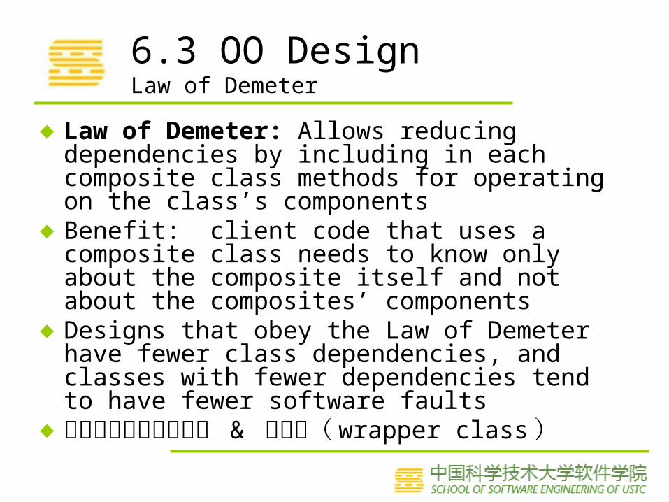
6.3 OO DesignLaw of Demeter
♦ Law of Demeter: Allows reducing dependencies by including in each composite class methods for operating on the class’s components
♦ Benefit: client code that uses a composite class needs to know only about the composite itself and not about the composites’ components
♦ Designs that obey the Law of Demeter have fewer class dependencies, and classes with fewer dependencies tend to have fewer software faults
♦ 不要和陌生人说话原则 & 包装类( wrapper class )

6.3 OO DesignDependency Inversion
♦ Dependency inversion is the last final OO design heuristic– used to reverse the direction of a dependency link between two
classes
♦ Dependency inversion works by introducing interfaces♦ The dependency inversion principle is used in the
definitions of several design patterns

6.4 Representing OO Designs in the UMLUML in the Process
♦ How UML is used in the development process
Requirements DesignArchitecture
UML use case
diagramsScenarios
UML activity
diagrams
UML state
diagrams
UML class
diagrams
UML object
diagrams
UML sequence diagrams
UML communicat
ion diagrams
UML package diagrams
UML component diagrams
UML deployment diagrams
Domain models
UML activity
diagrams

6.4 Representing OO Designs in the UMLTypes of Class Relationships
association
composition
aggregation
dependency
navigation
generalization

Royal Service Station Requirements
• Royal Service station provides three types of services
• The system must track bills, the product and services
• System to control inventory
• The system to track credit history, and payments overdue
• The system applies only to regular repeat customer
• The system must handle the data requirements for interfacing with other system
• The system must record tax and related information
• The station must be able to review tax record upon demand
• The system will send periodic message to customers
• Customer can rent parking space in the station parking lot
• The system maintain a repository of account information
• The station manager must be able to review accounting information upon demand
• The system can report an analysis of prices and discounts
• The system will automatically notify the owners of dormant accounts
• The system can not be unavailable for more than 24 hours
• The system must protect customer information from unauthorized access

Royal Service Station use case diagram
Manager

UML Class Diagram
♦ UML class diagrams describe the object types and their static relationships– Depict associations among objects and relationships between
types and subtypes– Diagrams should illustrate the attributes of each object, their
individual behaviors, and the restrictions on each class or object
♦ Look for and seek– Actors, physical objects, places, organizations, records,
transactions, collections of things, operations procedures, things manipulated by the system to be built

UML Class Diagram
• What needs to be “processed” in some way?• What items have multiple attributes?• When do you have more than one object in a
class?• What is based on the requirements
themselves, not derived from your understanding of the requirements?
• What attributes and operations are always applicable to a class or object?

Initial Grouping of Attributes and Classes: Step 1
Attributes Classes
Personal check Customer
Tax Maintenance
Price Services
Cash Fuel
Credit card Bill
Discounts Purchase
Station manager

Initial Grouping of Attributes and Classes: Step 2
Attributes Classes
Personal check Customer
Tax Maintenance
Price Services
Cash Parking
Credit card Fuel
Discounts Bill
Name Purchase
Address Maintenance reminder
Birthdate Station manager

Guidelines for Identifying Behaviors
• Imperative verbs• Passive verbs• Actions• Membership in• Management or ownership• Responsible for• Services provided by an organization

Initial Grouping of Attributes and Classes: Step 3
Attributes Classes
Personal checkTaxPriceCashCredit cardDiscountsNameAddressBirthdate
CustomerMaintenanceServicesParkingFuelBillPurchaseMaintenance reminderStation managerOverdue bill letterDormant account warningPartsAccountsInventoryCredit card systemPart ordering systemFuel ordering system
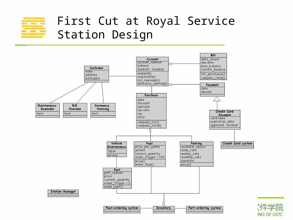
First Cut at Royal Service Station Design

UML Diagrams – Class Description Template
Class name: RefuelCategory: serviceExternal documents:Export control: PublicCardinality: nHierarchy:
Superclasses: ServiceAssociations:
<no rolename>: fuel in association updatesOperation name: price
Public member of: RefuelDocumentation:
// Calculates fuel final pricePreconditions:
gallons > 0Object diagram: (unspecified)

UML Diagrams – Class Description Template
Semantics:price = gallons * fuel.price_per_gallontax = price * purchase.tax_rateObject diagram: (unspecified)
Concurrency: sequentialPublic interface:
Operations:price
Private interface:Attributes:
gallonsImplementation:
Attributes:gallons
State machine: noConcurrency: sequentialPersistence: transient

Second Cut at Royal Service Station Design

Final Cut at Royal Service Station Design
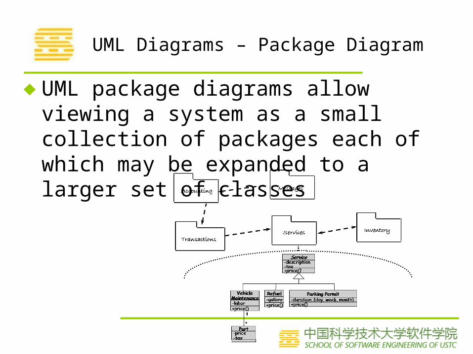
UML Diagrams – Package Diagram
♦ UML package diagrams allow viewing a system as a small collection of packages each of which may be expanded to a larger set of classes

UML Diagrams – SequenceDiagram
♦ Interaction diagrams describe how operations and behaviors are realized by the objects
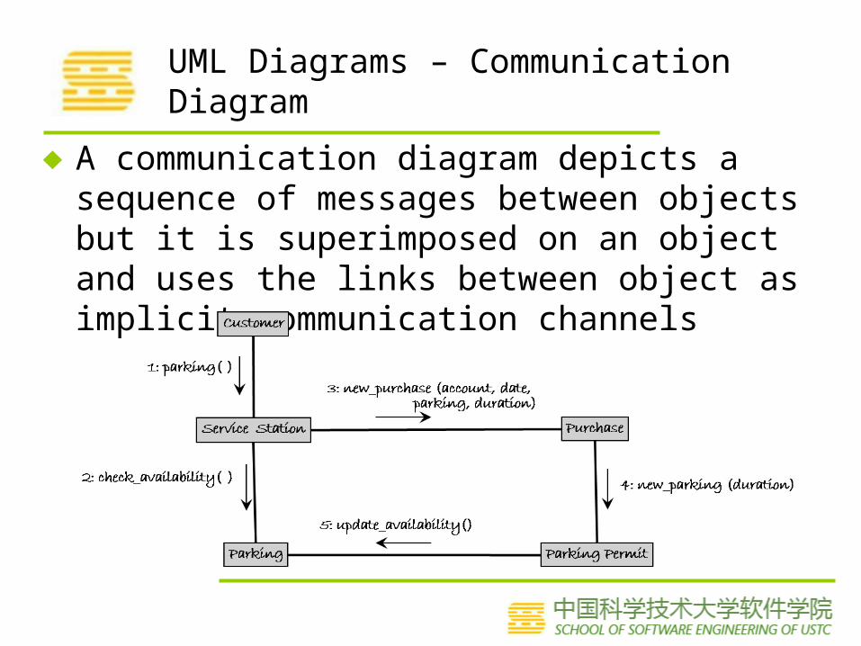
UML Diagrams – Communication Diagram
♦ A communication diagram depicts a sequence of messages between objects but it is superimposed on an object and uses the links between object as implicit communication channels

UML Diagrams – StateDiagram
♦ A state diagram shows the possible states an object can take, the events that trigger the transition between one state to the next, and the actions that result from each state change

UML Diagrams – State Diagram
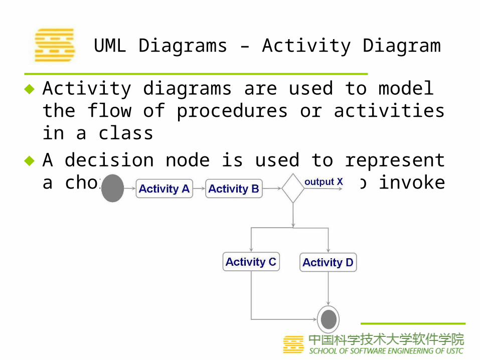
UML Diagrams – Activity Diagram
♦ Activity diagrams are used to model the flow of procedures or activities in a class
♦ A decision node is used to represent a choice of which activity to invoke

6.5 OO Design Patterns
• A design pattern codifies design decisions and best practices for solving a particular design problem according to design principles
• Design patterns are not the same as software libraries; they are not packaged solutions that can be used as is. Rather, they are templates for a solution that must be modified and adapted for each particular use

6.5 OO Design PatternsTemplate Method Pattern
• The Template Method pattern aims to reduce the amount of duplicate code among subclasses of the same parent class
– It is particularly useful when multiple subclasses have similar but not identical implementations of the same method
– This pattern addresses this problem by localizing the duplicate code structure in an abstract class from which the subclasses inherit
• The abstract class defines a template method that implements the common steps of an operation, and declares abstract primitive operations that represent the variation points

6.5 OO Design PatternsTemplate Method Pattern (continued)

6.5 OO Design PatternsFactory Method Pattern
• The Factory Method pattern is used to encapsulate the code that creates objects
• The factory Method pattern is similar to the Template method pattern
• The similar but not identical methods are the constructor methods that instantiate objects

6.5 OO Design PatternsStrategy Pattern
The Strategy pattern allows algorithms to be selected at runtimeIt is useful when various algorithms are available to an application
but the chose of best algorithm is not known

6.5 OO Design PatternsDecorator Pattern
The Decorator pattern is used to extend an object’s functionality at runtime
Decorator pattern is a flexible alternative to using inheritance at design time to create subclasses that support new features

6.5 OO Design PatternsObserver Pattern
The Observer pattern is an application of the publish–subscribe architecture style
Useful when software needs to notify multiple objects of key events

6.5 OO Design PatternsComposite Pattern
A composite object is a heterogeneous 异构 , possibly recursive 递归 , collection of objects that represents some composite entity
The composite pattern promotes the uses of a single uniform interface

6.5 OO Design PatternsVisitor Pattern
The Visitor pattern collects and encapsulates operation fragments into their own classes
Each operation is implemented as a separate subclass of an abstract Visitor class

6.5 OO Design PatternsApplication of Composite Pattern to Represent Math Expressions

6.6 Other Design ConsiderationsData Management
• Data management takes into account the system requirements concerning performance and space
• From an understanding of the data requirements and constraints, one lays out a design for the objects and their operations
• Four steps:– Identify the data, data structures, and relationships among them– Design services to manage the data structures and relationships– Find tools, such as database management systems, to implement
some of the data management tasks– Design classes and class hierarchies to oversee the data management
functions
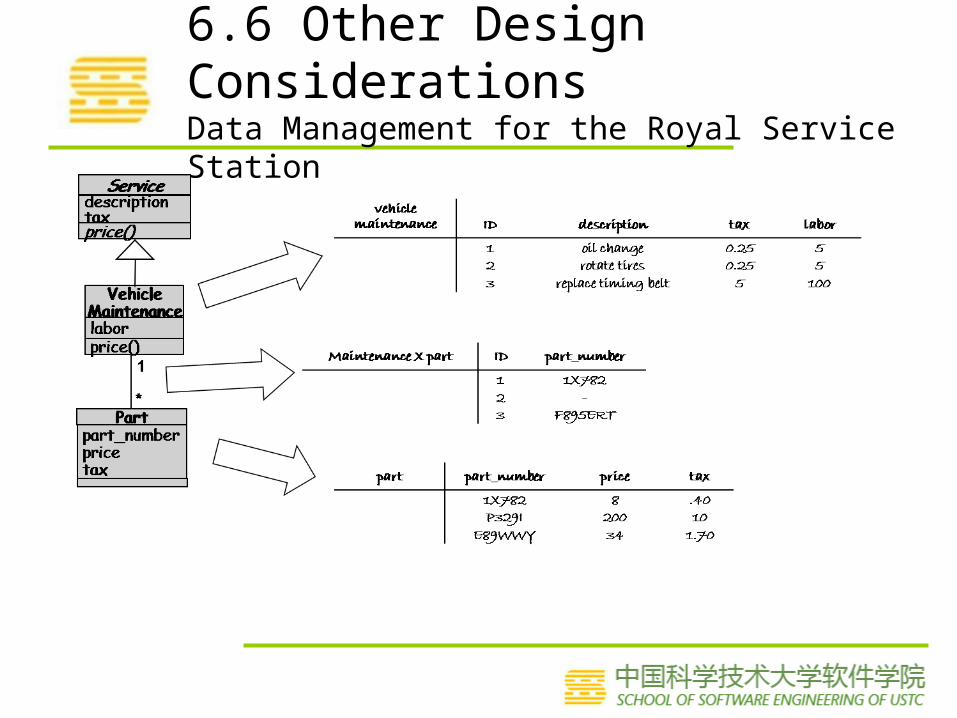
6.6 Other Design ConsiderationsData Management for the Royal Service Station

6.6 Other Design ConsiderationsDesigning User Interfaces
• Must consider several issues:– identifying the humans who will interact with the system– defining scenarios for each way that the system can
perform a task– designing a hierarchy of user commands– refining the sequence of user interactions with the system– designing relevant classes in the hierarchy to implement
the user-interface design– decisions– integrating the user-interface classes into the overall
system class hierarchy

6.6 Other Design ConsiderationsDesigning User Interfaces (continued)

6.6 Other Design ConsiderationsDesigning User Interfaces (continued)
6.6 Other Design ConsiderationsFrameworks
• A framework is a large reusable design for a specific application domain
• GUI editors, web applications, accounting systems• Different from software product lines
• Product lines are developed by a company for its own use
• Frameworks tend to be publically available resources like toolkits
• High-level architectures whose low-level details need to be filled-in

6.7 OO Measurement
♦ OO Size Measures♦ OO Design Quality Measures♦ Calculating the Degree of Cohesion

6.8 Design Documentation
• The details of the system architecture is documented in Software Architecture Document (SAD)
• SAD serves as a bridge between the requirements and the design
• Many ways to document the design• Design by contract: a particular approach that uses the
documentation only to capture the design but also to encourage interaction among developers

6.8 Design DocumentationDesign by Contract
Design contract between software provider and user

要点♦ Design Principles
– coupling and cohesion
♦ Inheritance, object composition, and polymorphism
♦ Strategy Pattern
♦ Observer Patter

谢谢大家!
References软件工程 - 理论与实践(第四版 影印版) Software Engineering: Theory and Practice (Fourth Edition),Shari Lawrence Pfleeger,Joanne M. Atlee ,高等教育出版社软件工程 - 理论与实践(第四版) Software Engineering: Theory and Practice (Fourth Edition),Shari Lawrence Pfleeger,Joanne M. Atlee, 杨卫东译 , 人民邮电出版社软件工程—实践者的研究方法( Software Engineering-A Practitioner’s Approach ) ; ( 美 ) Roger S. Pressman 著; 机械工业出版社 ISBN : 7-111-07282-0http://code.google.com/p/advancedsoftwareengineering/