Embed Size (px)
Citation preview
Page 13
Page 14
Detailed Design Study of North Java Corridor Flyover Project
Balaraja Flyover Substructure Design
KATAHIRA & ENGINEERS INTERNATIONAL
Page 1 9/16/2006
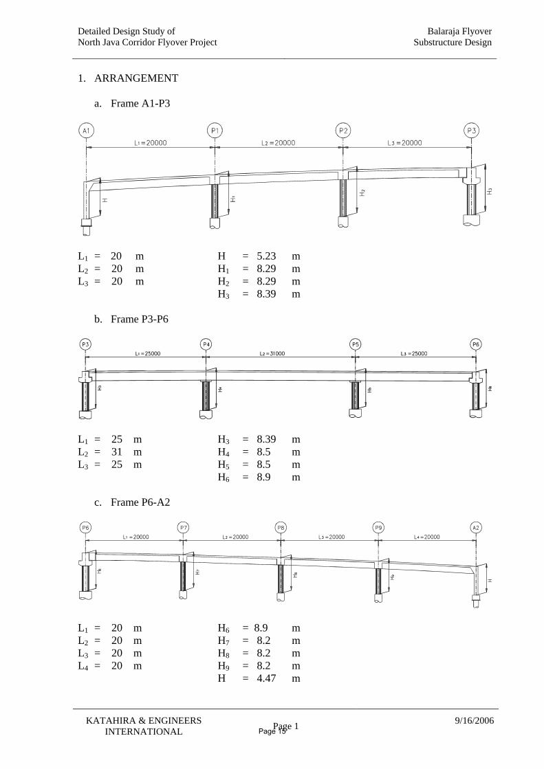
1. ARRANGEMENT
a. Frame A1-P3
L1 = 20 m H = 5.23 m L2 = 20 m H1 = 8.29 m L3 = 20 m H2 = 8.29 m H3 = 8.39 m
b. Frame P3-P6
L1 = 25 m H3 = 8.39 m L2 = 31 m H4 = 8.5 m L3 = 25 m H5 = 8.5 m H6 = 8.9 m
c. Frame P6-A2
L1 = 20 m H6 = 8.9 m L2 = 20 m H7 = 8.2 m L3 = 20 m H8 = 8.2 m L4 = 20 m H9 = 8.2 m H = 4.47 m
Page 15
Detailed Design Study of North Java Corridor Flyover Project
BALARAJA FLYOVER DETAILED DESIGN
SUBSTRUCTURE
Katahira & Engineers International
2. SECTION PROPERTIES and MATERIAL PROPERTIES
Page 16
Detailed Design Study of North Java Corridor Flyover Project
BALARAJA FLYOVER DETAILED DESIGN
SUBSTUCTURE
Katahira & Engineers International
8/18/2006
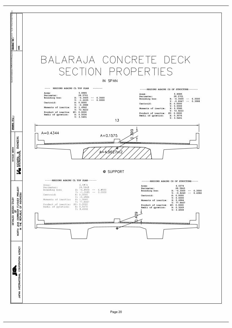
2.1 CONCRETE DECK SECTION PROPERTIES
Page 17
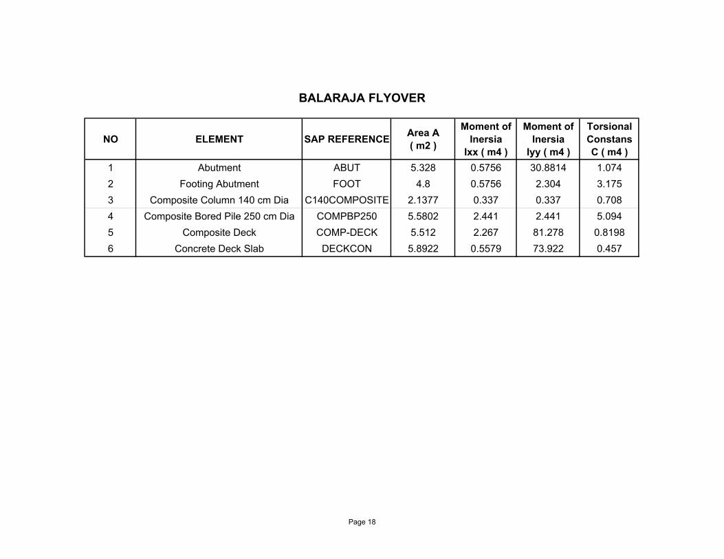
NO ELEMENT SAP REFERENCE Area A ( m2 )
Moment of Inersia
Ixx ( m4 )
Moment of Inersia
Iyy ( m4 )
Torsional Constans C ( m4 )
1 Abutment ABUT 5.328 0.5756 30.8814 1.0742 Footing Abutment FOOT 4.8 0.5756 2.304 3.1753 Composite Column 140 cm Dia C140COMPOSITE 2.1377 0.337 0.337 0.7084 Composite Bored Pile 250 cm Dia COMPBP250 5.5802 2.441 2.441 5.0945 Composite Deck COMP-DECK 5.512 2.267 81.278 0.81986 Concrete Deck Slab DECKCON 5.8922 0.5579 73.922 0.457
BALARAJA FLYOVER
Page 18
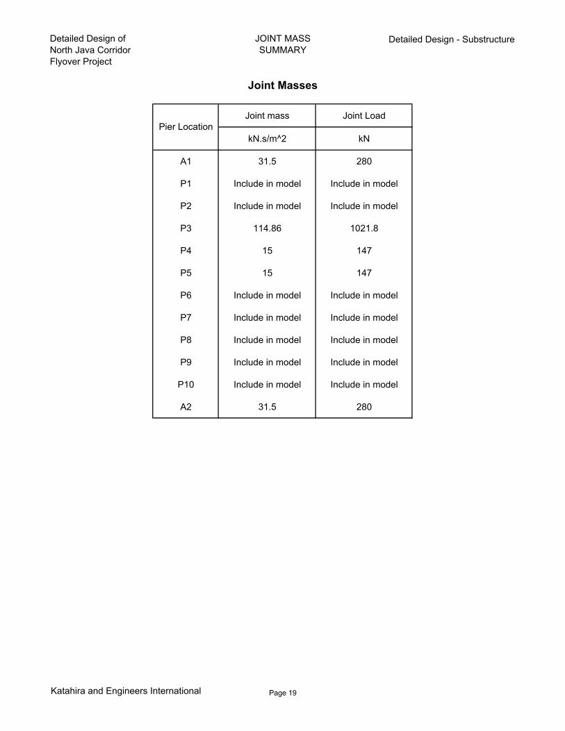
Detailed Design ofNorth Java Corridor Flyover Project
JOINT MASSSUMMARY
Detailed Design - Substructure
Joint mass Joint Load
kN.s/m^2 kN
A1 31.5 280
P1 Include in model Include in model
P2 Include in model Include in model
P3 114.86 1021.8
P4 15 147
P5 15 147
P6 Include in model Include in model
P7 Include in model Include in model
P8 Include in model Include in model
P9 Include in model Include in model
P10 Include in model Include in model
A2 31.5 280
Pier Location
Joint Masses
Katahira and Engineers International Page 19
Page 20
Detailed Design Study of North Java Corridor Flyover Project
BALARAJA FLYOVER DETAILED DESIGN
SUBSTUCTURE
Katahira & Engineers International
8/18/2006
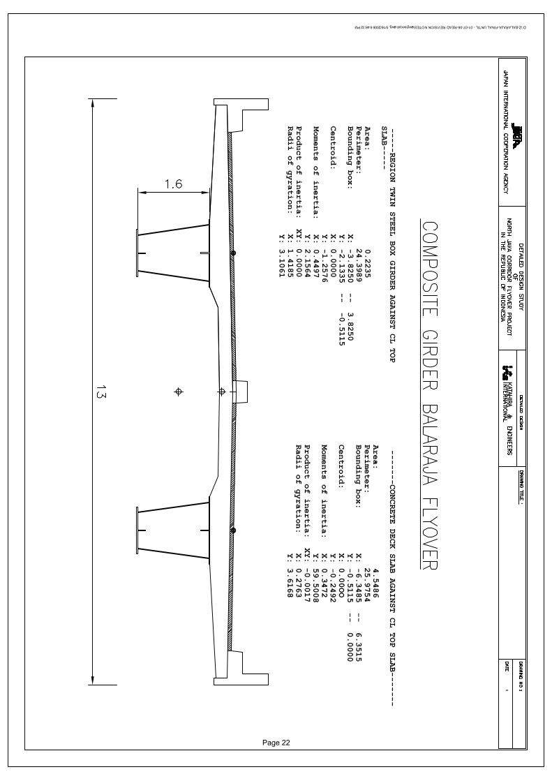
2.2 STEEL DECK SECTION PROPERTIES
Page 21
Page 22
Detailed Design Study of North Java Corridor Flyover Project
BALARAJA FLYOVER DETAILED DESIGN
SUBSTRUCTURE
Katahira & Engineers International
2.3 COMPOSITE COLUMN AND COMPOSITE
PILE TOP SECTION PROPERTIES
Page 23
Detailed Design Study ofNorth Java Corridor Flyover Project
Detailed Design SubstructureBalaraja Flyover
Torsion Properties
KATAHIRA & ENGINEERSINTERNATIONAL
Project: Detailed Design Study ofNorth Java Corridor Flyover Project
Calculation: Detailed Design SubstructureBalaraja FlyoverComposite Bored Piles & Coloumn Torsion Properties
Initial Data
Modulus of elasticity of steel Es 200000 MPa⋅:=
Characteristic strength of RCconcrete
fc 30 MPa⋅:=
Modulus of elasticity of concrete Ec 4700fc
MPa⋅ MPa⋅:= Ec 25743 MPa=
Modular ratio wth respect to concreteαc
EsEc
:= αc 7.769=
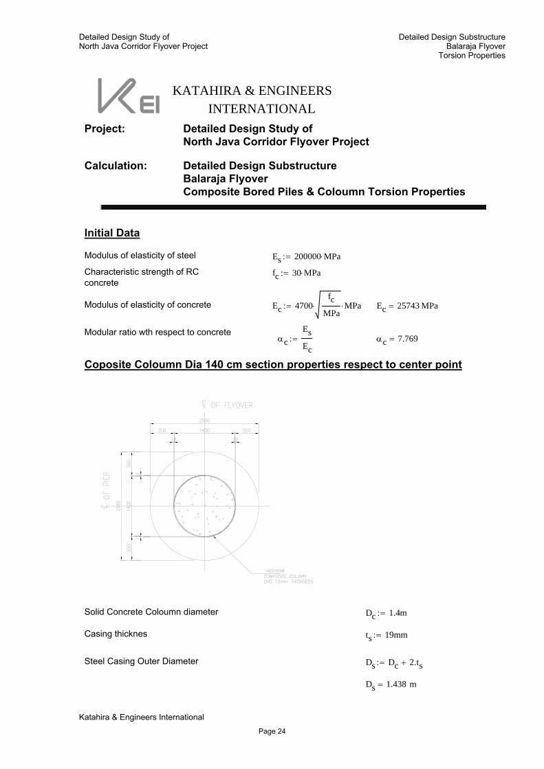
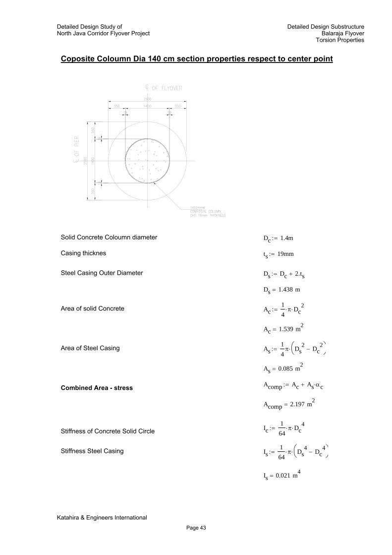
Coposite Coloumn Dia 140 cm section properties respect to center point
Solid Concrete Coloumn diameter Dc 1.4m:=
Casing thicknes ts 19mm:=
Steel Casing Outer Diameter Ds Dc 2.ts+:=
Ds 1.438 m=
Katahira & Engineers International
Page 24
Detailed Design Study ofNorth Java Corridor Flyover Project
Detailed Design SubstructureBalaraja Flyover
Torsion Properties
Area of solid Concrete Ac14π⋅ Dc
2⋅:=
Ac 1.539 m2=
Area of Steel Casing As14π Ds
2 Dc2
−⎛⎝
⎞⎠⋅:=
As 0.085 m2=
Acomp Ac As αc⋅+:=Combined Area - stress
Acomp 2.197 m2=
Ic164
π⋅ Dc4
⋅:=Stiffness of Concrete Solid Circle
Stiffness Steel Casing Is164
π⋅ Ds4 Dc
4−⎛
⎝⎞⎠⋅:=
Is 0.021 m4=
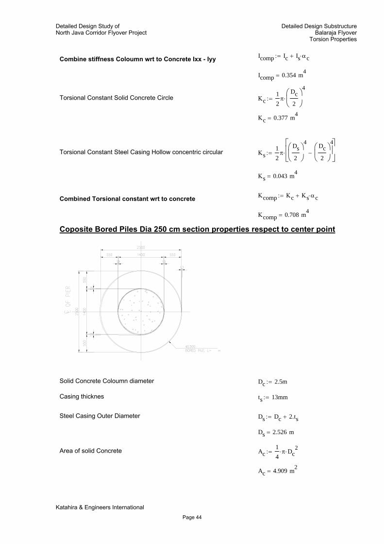
Icomp Ic Is αc⋅+:=Combine stiffness Coloumn wrt to Concrete Ixx - Iyy
Icomp 0.354 m4=
Torsional Constant Solid Concrete Circle Κc12π
Dc2
⎛⎜⎝
⎞⎟⎠
4
⋅:=
Κc 0.377 m4=
Torsional Constant Steel Casing Hollow concentric circular Κs12π
Ds2
⎛⎜⎝
⎞⎟⎠
4 Dc2
⎛⎜⎝
⎞⎟⎠
4
−⎡⎢⎢⎣
⎤⎥⎥⎦
⋅:=
Κs 0.043 m4=
Κcomp Κc Κs αc⋅+:=Combined Torsional constant wrt to concrete
Κcomp 0.708 m4=
Katahira & Engineers International
Page 25
Detailed Design Study ofNorth Java Corridor Flyover Project
Detailed Design SubstructureBalaraja Flyover
Torsion Properties
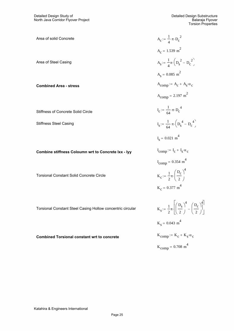
Coposite Bored Piles Dia 250 cm section properties respect to center point
Solid Concrete Coloumn diameter Dc 2.5m:=
Casing thicknes ts 13mm:=
Steel Casing Outer Diameter Ds Dc 2.ts+:=
Ds 2.526 m=
Area of solid Concrete Ac14π⋅ Dc
2⋅:=
Ac 4.909 m2=
Area of Steel Casing As14π Ds
2 Dc2
−⎛⎝
⎞⎠⋅:=
As 0.103 m2=
Acomp Ac As αc⋅+:=Combined Area - stress
Acomp 5.706 m2=
Ic164
π⋅ Dc4
⋅:=Stiffness of Concrete Solid Circle
Stiffness Steel Casing Is164
π⋅ Ds4 Dc
4−⎛
⎝⎞⎠⋅:=
Is 0.081 m4=
Katahira & Engineers International
Page 26
Detailed Design Study of North Java Corridor Flyover Project
BALARAJA FLYOVER DETAILED DESIGN
SUBSTRUCTURE
Katahira & Engineers International
2.4. ABUTMENT AND PIER COPING SECTION PROPERTIES
Page 27
KATAHIRA & ENGINEERSINTERNATIONAL
Project: Detailed Design Study ofNorth Java Corridor Flyover Project
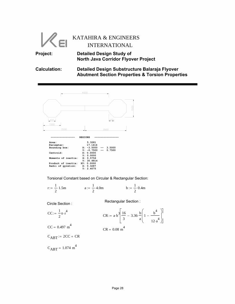
Calculation: Detailed Design Substructure Balaraja FlyoverAbutment Section Properties & Torsion Properties
---------------- REGIONS ----------------
Area: 5.3281Perimeter: 17.1414Bounding box: X: -3.5000 -- 3.5000 Y: -0.7500 -- 0.7500Centroid: X: 0.0000 Y: 0.0000Moments of inertia: X: 0.5756 Y: 30.8814Product of inertia: XY: 0.0000Radii of gyration: X: 0.3287 Y: 2.4075
Torsional Constant based on Circular & Rectangular Section:
r12
1.5⋅ m:= a12
4.0⋅ m:= b12
0.4⋅ m:=
Rectangular Section :Circle Section :
CC12π r4⋅:= CR a b3
⋅163
3.36ba⋅ 1
b4
12 a4⋅
−⎛⎜⎜⎝
⎞⎟⎟⎠
−⎡⎢⎢⎣
⎤⎥⎥⎦
:=
CC 0.497 m4= CR 0.08 m4
=
CABT 2CC CR+:=
CABT 1.074 m4=
Page 28
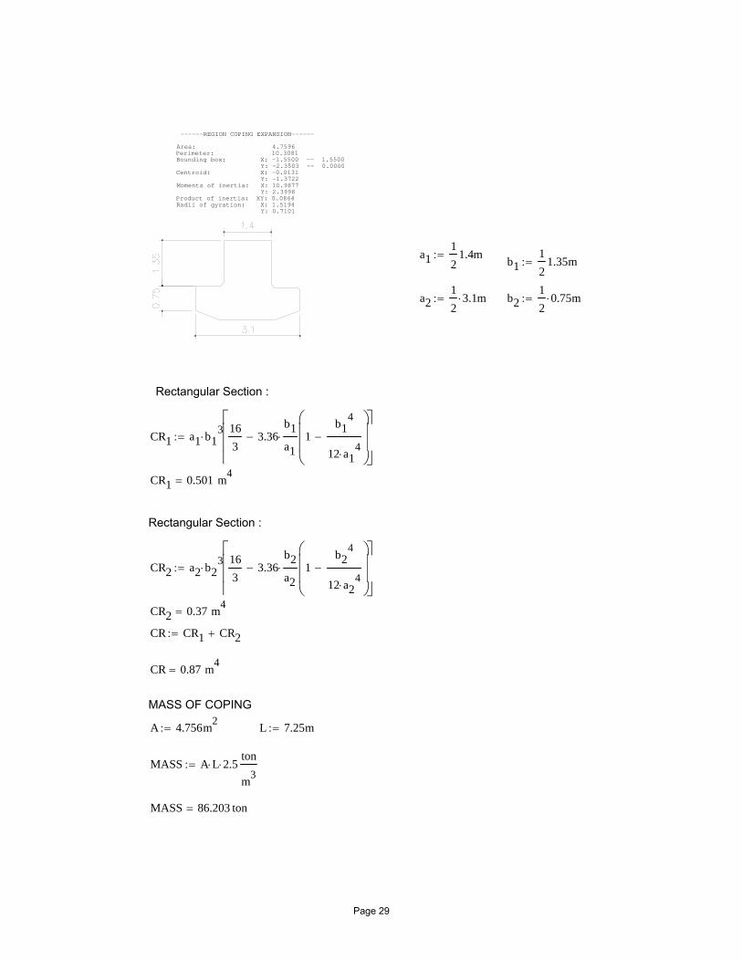
------REGION COPING EXPANSION------
Area: 4.7596Perimeter: 10.3081Bounding box: X: -1.5500 -- 1.5500 Y: -2.3503 -- 0.0000Centroid: X: -0.0131 Y: -1.3722Moments of inertia: X: 10.9877 Y: 2.3998Product of inertia: XY: 0.0864Radii of gyration: X: 1.5194 Y: 0.7101
a112
1.4m:= b112
1.35m:=
a212
3.1⋅ m:= b212
0.75⋅ m:=
Rectangular Section :
CR1 a1 b13
⋅163
3.36b1a1⋅ 1
b14
12 a14
⋅−
⎛⎜⎜⎝
⎞⎟⎟⎠
−⎡⎢⎢⎣
⎤⎥⎥⎦
:=
CR1 0.501 m4=
Rectangular Section :
CR2 a2 b23
⋅163
3.36b2a2⋅ 1
b24
12 a24
⋅−
⎛⎜⎜⎝
⎞⎟⎟⎠
−⎡⎢⎢⎣
⎤⎥⎥⎦
:=
CR2 0.37 m4=
CR CR1 CR2+:=
CR 0.87 m4=
MASS OF COPING
A 4.756m2:= L 7.25m:=
MASS A L⋅ 2.5⋅ton
m3:=
MASS 86.203 ton=
Page 29
Detailed Design Study of North Java Corridor Flyover Project
BALARAJA FLYOVER DETAILED DESIGN
SUBSTRUCTURE
Katahira & Engineers International
2.5. TORSION PROPERTIES
Page 30
Detailed Design Study ofNorth Java Corridor Flyover Project
Detailed Design SubstructureBalaraja Flyover
Torsion Properties
KATAHIRA & ENGINEERSINTERNATIONAL
Project: Detailed Design Study ofNorth Java Corridor Flyover Project
Calculation: Detailed Design SubstructureBalaraja FlyoverTorsion Properties
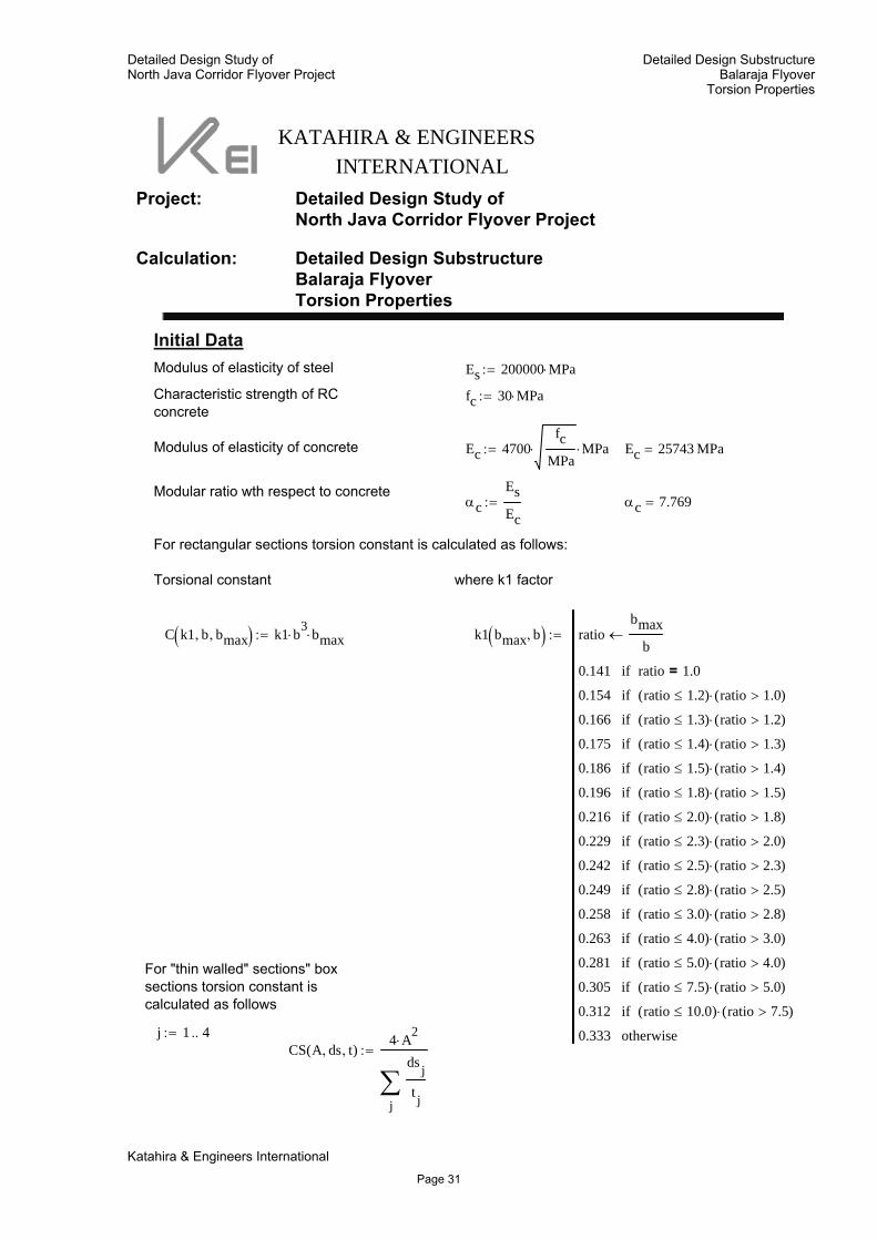
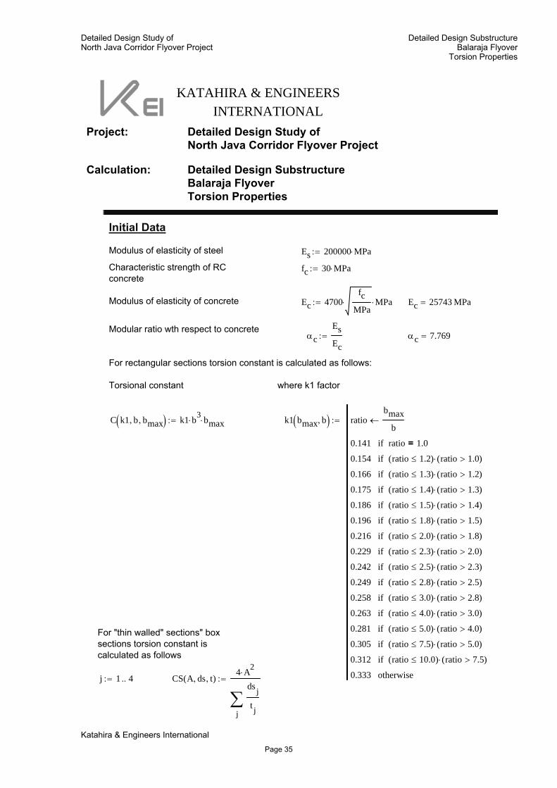
Initial DataModulus of elasticity of steel Es 200000 MPa⋅:=
Characteristic strength of RCconcrete
fc 30 MPa⋅:=
Modulus of elasticity of concrete Ec 4700fc
MPa⋅ MPa⋅:= Ec 25743 MPa=
Modular ratio wth respect to concreteαc
EsEc
:= αc 7.769=
For rectangular sections torsion constant is calculated as follows:
Torsional constant where k1 factor
C k1 b, bmax,( ) k1 b3⋅ bmax⋅:= k1 bmax b,( ) ratio
bmaxb
←
0.141 ratio 1.0=if
0.154 ratio 1.2≤( ) ratio 1.0>( )⋅if
0.166 ratio 1.3≤( ) ratio 1.2>( )⋅if
0.175 ratio 1.4≤( ) ratio 1.3>( )⋅if
0.186 ratio 1.5≤( ) ratio 1.4>( )⋅if
0.196 ratio 1.8≤( ) ratio 1.5>( )⋅if
0.216 ratio 2.0≤( ) ratio 1.8>( )⋅if
0.229 ratio 2.3≤( ) ratio 2.0>( )⋅if
0.242 ratio 2.5≤( ) ratio 2.3>( )⋅if
0.249 ratio 2.8≤( ) ratio 2.5>( )⋅if
0.258 ratio 3.0≤( ) ratio 2.8>( )⋅if
0.263 ratio 4.0≤( ) ratio 3.0>( )⋅if
0.281 ratio 5.0≤( ) ratio 4.0>( )⋅if
0.305 ratio 7.5≤( ) ratio 5.0>( )⋅if
0.312 ratio 10.0≤( ) ratio 7.5>( )⋅if
0.333 otherwise
:=
For "thin walled" sections" boxsections torsion constant iscalculated as follows
j 1 4..:=CS A ds, t,( )
4 A2⋅
j
ds j
t j∑
:=
Katahira & Engineers International
Page 31
Detailed Design Study ofNorth Java Corridor Flyover Project
Detailed Design SubstructureBalaraja Flyover
Torsion Properties
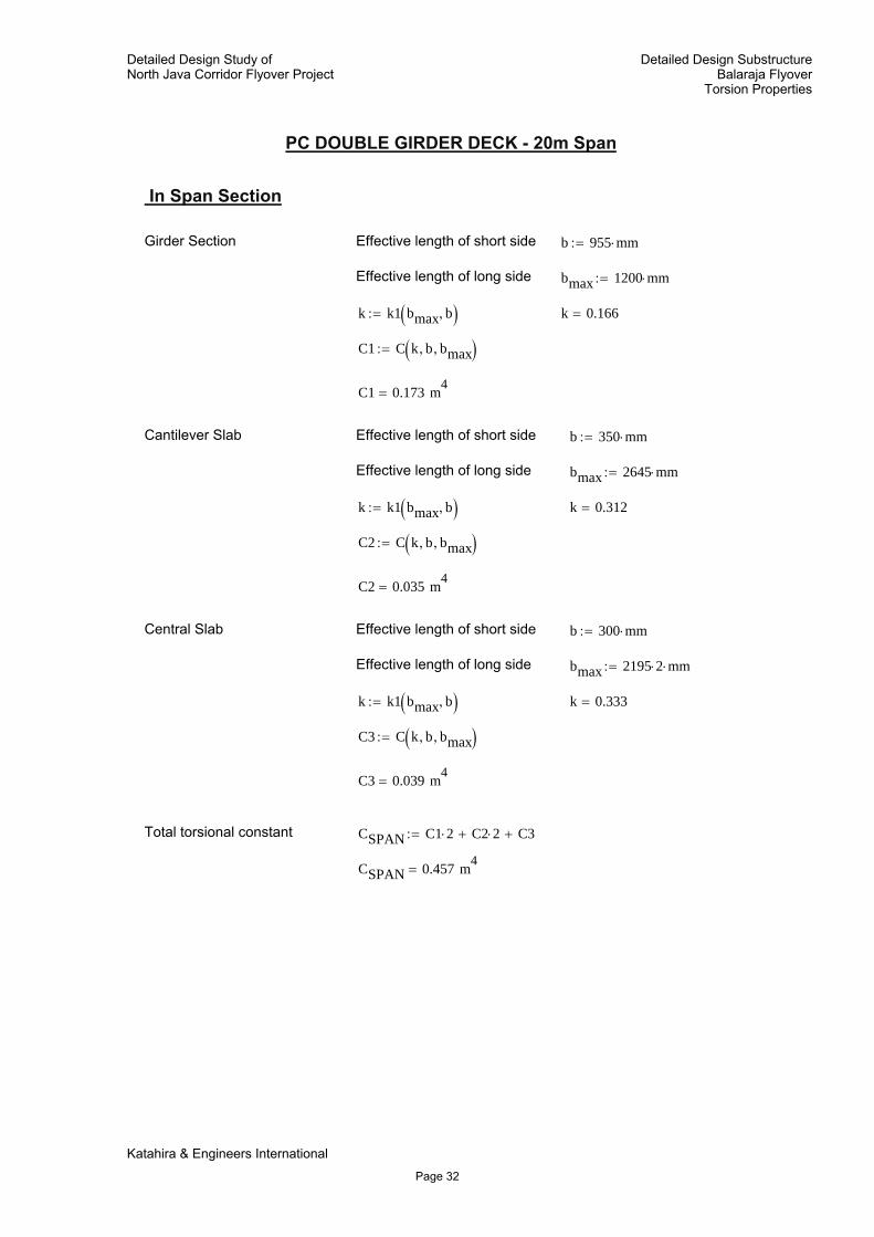
PC DOUBLE GIRDER DECK - 20m Span
In Span Section
Girder Section Effective length of short side b 955 mm⋅:=
Effective length of long side bmax 1200 mm⋅:=
k k1 bmax b,( ):= k 0.166=
C1 C k b, bmax,( ):=
C1 0.173 m4=
Cantilever Slab Effective length of short side b 350 mm⋅:=
Effective length of long side bmax 2645 mm⋅:=
k k1 bmax b,( ):= k 0.312=
C2 C k b, bmax,( ):=
C2 0.035 m4=
Central Slab Effective length of short side b 300 mm⋅:=
Effective length of long side bmax 2195 2⋅ mm⋅:=
k k1 bmax b,( ):= k 0.333=
C3 C k b, bmax,( ):=
C3 0.039 m4=
Total torsional constant CSPAN C1 2⋅ C2 2⋅+ C3+:=
CSPAN 0.457 m4=
Katahira & Engineers International
Page 32
Detailed Design Study ofNorth Java Corridor Flyover Project
Detailed Design SubstructureBalaraja Flyover
Torsion Properties
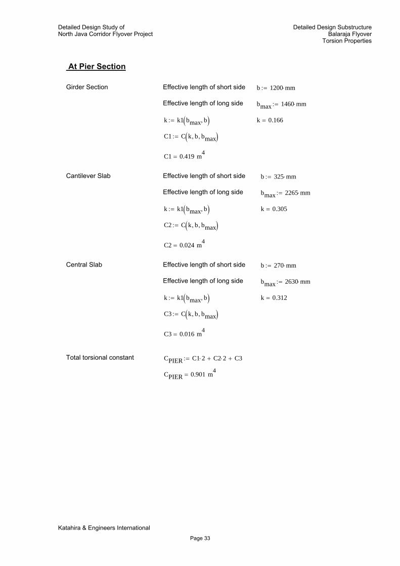
At Pier Section
Girder Section Effective length of short side b 1200 mm⋅:=
Effective length of long side bmax 1460 mm⋅:=
k k1 bmax b,( ):= k 0.166=
C1 C k b, bmax,( ):=
C1 0.419 m4=
Cantilever Slab Effective length of short side b 325 mm⋅:=
Effective length of long side bmax 2265 mm⋅:=
k k1 bmax b,( ):= k 0.305=
C2 C k b, bmax,( ):=
C2 0.024 m4=
Central Slab Effective length of short side b 270 mm⋅:=
Effective length of long side bmax 2630 mm⋅:=
k k1 bmax b,( ):= k 0.312=
C3 C k b, bmax,( ):=
C3 0.016 m4=
Total torsional constant CPIER C1 2⋅ C2 2⋅+ C3+:=
CPIER 0.901 m4=
Katahira & Engineers International
Page 33
Detailed Design Study ofNorth Java Corridor Flyover Project
Detailed Design SubstructureBalaraja Flyover
Torsion Properties
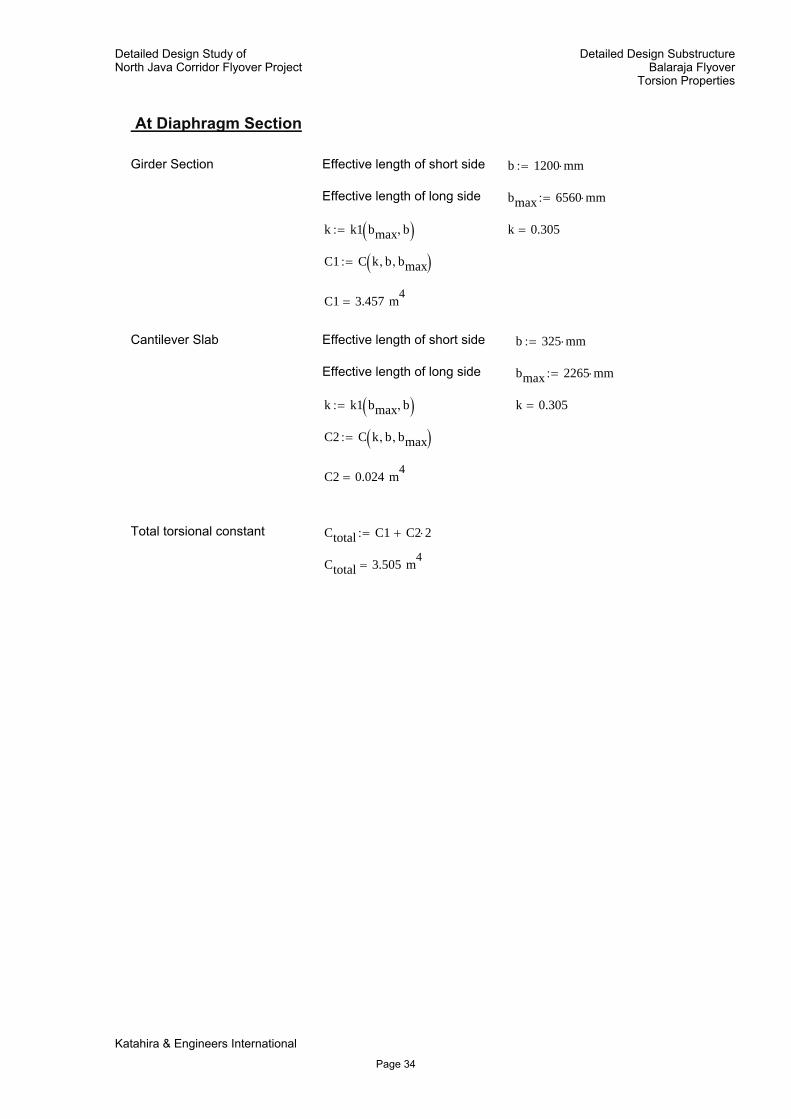
At Diaphragm Section
Girder Section Effective length of short side b 1200 mm⋅:=
Effective length of long side bmax 6560 mm⋅:=
k k1 bmax b,( ):= k 0.305=
C1 C k b, bmax,( ):=
C1 3.457 m4=
Cantilever Slab Effective length of short side b 325 mm⋅:=
Effective length of long side bmax 2265 mm⋅:=
k k1 bmax b,( ):= k 0.305=
C2 C k b, bmax,( ):=
C2 0.024 m4=
Total torsional constant Ctotal C1 C2 2⋅+:=
Ctotal 3.505 m4=
Katahira & Engineers International
Page 34
Detailed Design Study ofNorth Java Corridor Flyover Project
Detailed Design SubstructureBalaraja Flyover
Torsion Properties
KATAHIRA & ENGINEERSINTERNATIONAL
Project: Detailed Design Study ofNorth Java Corridor Flyover Project
Calculation: Detailed Design SubstructureBalaraja FlyoverTorsion Properties
Initial Data
Modulus of elasticity of steel Es 200000 MPa⋅:=
Characteristic strength of RCconcrete
fc 30 MPa⋅:=
Modulus of elasticity of concrete Ec 4700fc
MPa⋅ MPa⋅:= Ec 25743 MPa=
Modular ratio wth respect to concreteαc
EsEc
:= αc 7.769=
For rectangular sections torsion constant is calculated as follows:
Torsional constant where k1 factor
C k1 b, bmax,( ) k1 b3⋅ bmax⋅:= k1 bmax b,( ) ratio
bmaxb
←
0.141 ratio 1.0=if
0.154 ratio 1.2≤( ) ratio 1.0>( )⋅if
0.166 ratio 1.3≤( ) ratio 1.2>( )⋅if
0.175 ratio 1.4≤( ) ratio 1.3>( )⋅if
0.186 ratio 1.5≤( ) ratio 1.4>( )⋅if
0.196 ratio 1.8≤( ) ratio 1.5>( )⋅if
0.216 ratio 2.0≤( ) ratio 1.8>( )⋅if
0.229 ratio 2.3≤( ) ratio 2.0>( )⋅if
0.242 ratio 2.5≤( ) ratio 2.3>( )⋅if
0.249 ratio 2.8≤( ) ratio 2.5>( )⋅if
0.258 ratio 3.0≤( ) ratio 2.8>( )⋅if
0.263 ratio 4.0≤( ) ratio 3.0>( )⋅if
0.281 ratio 5.0≤( ) ratio 4.0>( )⋅if
0.305 ratio 7.5≤( ) ratio 5.0>( )⋅if
0.312 ratio 10.0≤( ) ratio 7.5>( )⋅if
0.333 otherwise
:=
For "thin walled" sections" boxsections torsion constant iscalculated as follows
j 1 4..:= CS A ds, t,( )4 A2⋅
j
ds j
t j∑
:=
Katahira & Engineers International
Page 35
Detailed Design Study ofNorth Java Corridor Flyover Project
Detailed Design SubstructureBalaraja Flyover
Torsion Properties
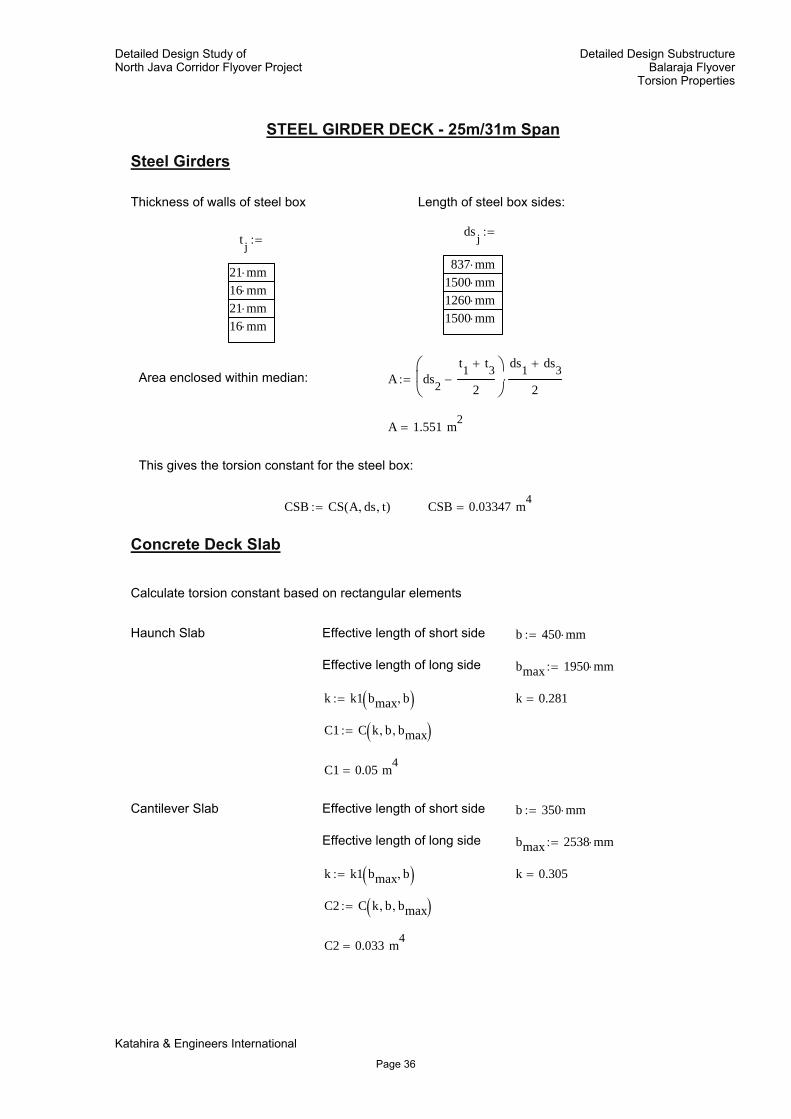
STEEL GIRDER DECK - 25m/31m Span
Steel Girders
Thickness of walls of steel box Length of steel box sides:
ds j
837 mm⋅1500 mm⋅1260 mm⋅1500 mm⋅
:=t j
21 mm⋅16 mm⋅21 mm⋅16 mm⋅
:=
Area enclosed within median: A ds2
t1 t3+
2−
⎛⎜⎝
⎞⎟⎠
ds1 ds3+
2⋅:=
A 1.551 m2=
This gives the torsion constant for the steel box:
CSB CS A ds, t,( ):= CSB 0.03347 m4=
Concrete Deck Slab
Calculate torsion constant based on rectangular elements
Haunch Slab Effective length of short side b 450 mm⋅:=
Effective length of long side bmax 1950 mm⋅:=
k k1 bmax b,( ):= k 0.281=
C1 C k b, bmax,( ):=
C1 0.05 m4=
Cantilever Slab Effective length of short side b 350 mm⋅:=
Effective length of long side bmax 2538 mm⋅:=
k k1 bmax b,( ):= k 0.305=
C2 C k b, bmax,( ):=
C2 0.033 m4=
Katahira & Engineers International
Page 36
Detailed Design Study ofNorth Java Corridor Flyover Project
Detailed Design SubstructureBalaraja Flyover
Torsion Properties
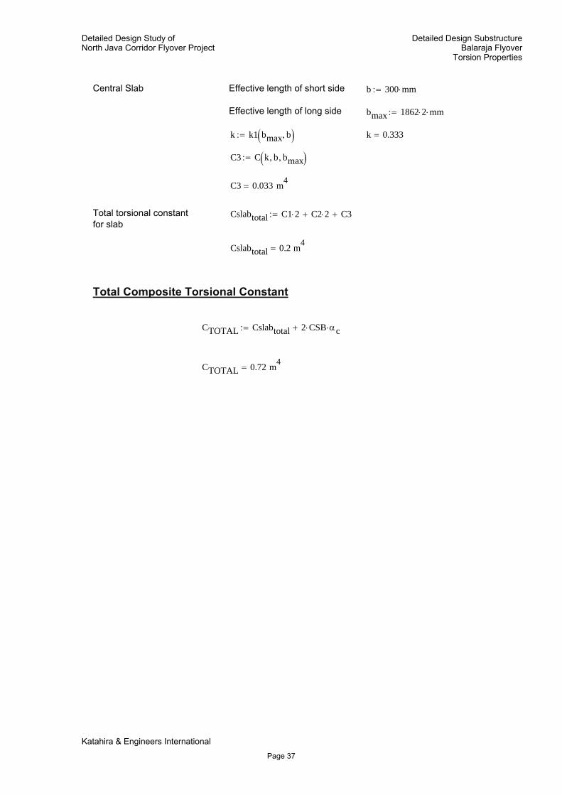
Central Slab Effective length of short side b 300 mm⋅:=
Effective length of long side bmax 1862 2⋅ mm⋅:=
k k1 bmax b,( ):= k 0.333=
C3 C k b, bmax,( ):=
C3 0.033 m4=
Total torsional constantfor slab
Cslabtotal C1 2⋅ C2 2⋅+ C3+:=
Cslabtotal 0.2 m4=
Total Composite Torsional Constant
CTOTAL Cslabtotal 2 CSB⋅ αc⋅+:=
CTOTAL 0.72 m4=
Katahira & Engineers International
Page 37
Detailed Design Study ofNorth Java Corridor Flyover Project
Detailed Design SubstructureBalaraja Flyover
Torsion Properties
KATAHIRA & ENGINEERSINTERNATIONAL
Project: Detailed Design Study ofNorth Java Corridor Flyover Project
Calculation: Detailed Design SubstructureBalaraja FlyoverTorsion Properties
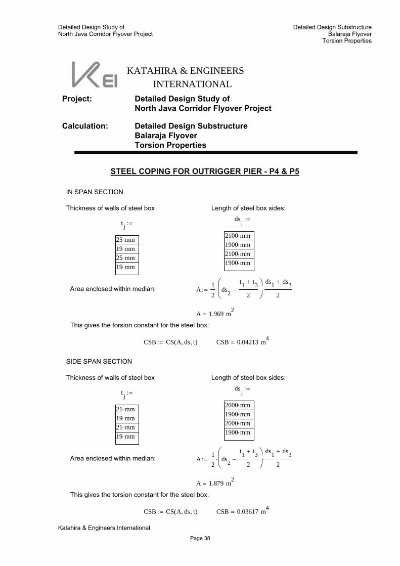
STEEL COPING FOR OUTRIGGER PIER - P4 & P5
IN SPAN SECTION
Thickness of walls of steel box Length of steel box sides:ds j
2100 mm⋅1900 mm⋅2100 mm⋅1900 mm⋅
:=t j
25 mm⋅19 mm⋅25 mm⋅19 mm⋅
:=
Area enclosed within median: A12
ds2
t1 t3+
2−
⎛⎜⎝
⎞⎟⎠
⋅ds1 ds3+
2⋅:=
A 1.969 m2=
This gives the torsion constant for the steel box:
CSB CS A ds, t,( ):= CSB 0.04213 m4=
SIDE SPAN SECTION
Thickness of walls of steel box Length of steel box sides:ds j
2000 mm⋅1900 mm⋅2000 mm⋅1900 mm⋅
:=t j
21 mm⋅19 mm⋅21 mm⋅19 mm⋅
:=
Area enclosed within median: A12
ds2
t1 t3+
2−
⎛⎜⎝
⎞⎟⎠
⋅ds1 ds3+
2⋅:=
A 1.879 m2=
This gives the torsion constant for the steel box:
CSB CS A ds, t,( ):= CSB 0.03617 m4=
Katahira & Engineers International
Page 38
Detailed Design Study ofNorth Java Corridor Flyover Project
Detailed Design SubstructureBalaraja Flyover
Torsion Properties
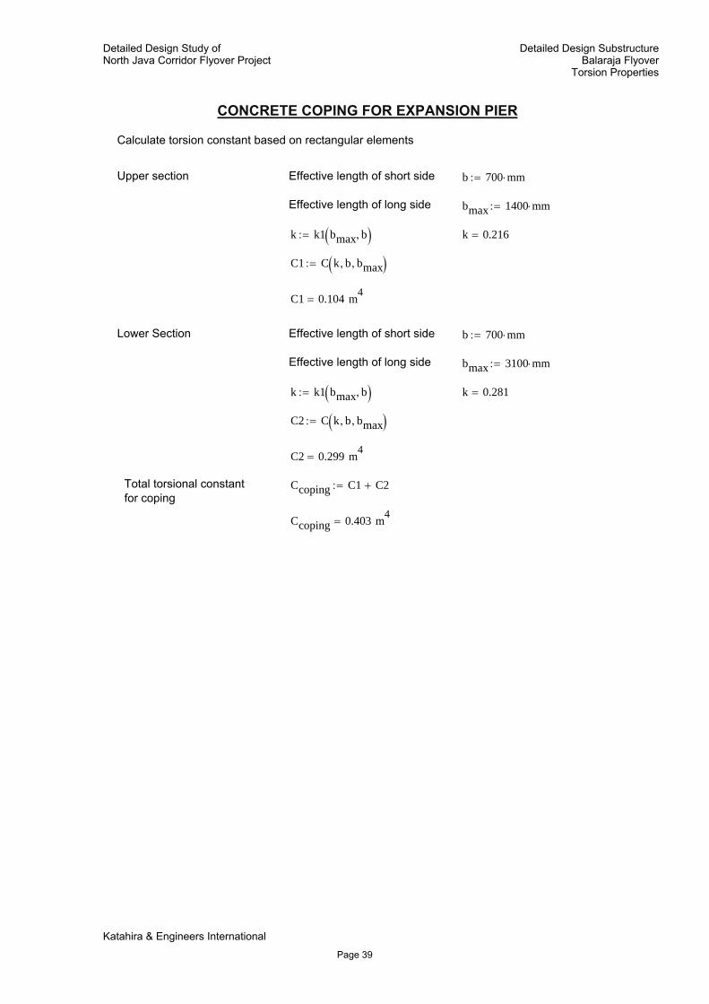
CONCRETE COPING FOR EXPANSION PIER
Calculate torsion constant based on rectangular elements
Upper section Effective length of short side b 700 mm⋅:=
Effective length of long side bmax 1400 mm⋅:=
k k1 bmax b,( ):= k 0.216=
C1 C k b, bmax,( ):=
C1 0.104 m4=
Lower Section Effective length of short side b 700 mm⋅:=
Effective length of long side bmax 3100 mm⋅:=
k k1 bmax b,( ):= k 0.281=
C2 C k b, bmax,( ):=
C2 0.299 m4=
Total torsional constantfor coping
Ccoping C1 C2+:=
Ccoping 0.403 m4=
Katahira & Engineers International
Page 39
Detailed Design Study ofNorth Java Corridor Flyover Project
Detailed Design SubstructureBalaraja Flyover
Torsion Properties
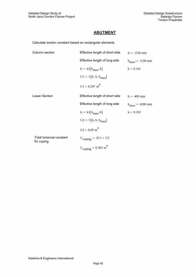
ABUTMENT
Calculate torsion constant based on rectangular elements
Column section Effective length of short side b 1150 mm⋅:=
Effective length of long side bmax 1150 mm⋅:=
k k1 bmax b,( ):= k 0.141=
C1 C k b, bmax,( ):=
C1 0.247 m4=
Lower Section Effective length of short side b 400 mm⋅:=
Effective length of long side bmax 4200 mm⋅:=
k k1 bmax b,( ):= k 0.333=
C2 C k b, bmax,( ):=
C2 0.09 m4=
Total torsional constantfor coping
Ccoping 2C1 C2+:=
Ccoping 0.583 m4=
Katahira & Engineers International
Page 40
Detailed Design Study ofNorth Java Corridor Flyover Project
Detailed Design SubstructureBalaraja Flyover
Torsion Properties
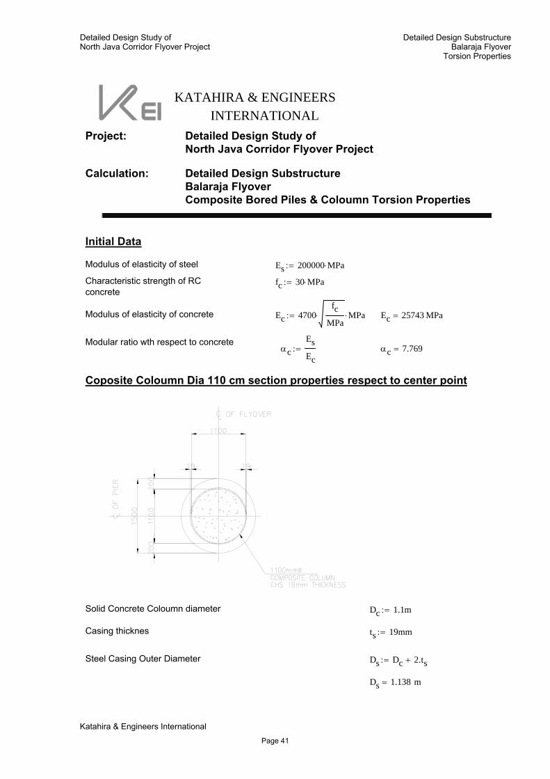
KATAHIRA & ENGINEERSINTERNATIONAL
Project: Detailed Design Study ofNorth Java Corridor Flyover Project
Calculation: Detailed Design SubstructureBalaraja FlyoverComposite Bored Piles & Coloumn Torsion Properties
Initial Data
Modulus of elasticity of steel Es 200000 MPa⋅:=
Characteristic strength of RCconcrete
fc 30 MPa⋅:=
Modulus of elasticity of concrete Ec 4700fc
MPa⋅ MPa⋅:= Ec 25743 MPa=
Modular ratio wth respect to concreteαc
EsEc
:= αc 7.769=
Coposite Coloumn Dia 110 cm section properties respect to center point
Solid Concrete Coloumn diameter Dc 1.1m:=
Casing thicknes ts 19mm:=
Steel Casing Outer Diameter Ds Dc 2.ts+:=
Ds 1.138 m=
Katahira & Engineers International
Page 41
Detailed Design Study ofNorth Java Corridor Flyover Project
Detailed Design SubstructureBalaraja Flyover
Torsion Properties
Area of solid Concrete Ac14π⋅ Dc
2⋅:=
Ac 0.95 m2=
Area of Steel Casing As14π Ds
2 Dc2
−⎛⎝
⎞⎠⋅:=
As 0.067 m2=
Acomp Ac As αc⋅+:=Combined Area - stress
Acomp 1.469 m2=
Ic164
π⋅ Dc4
⋅:=Stiffness of Concrete Solid Circle
Stiffness Steel Casing Is164
π⋅ Ds4 Dc
4−⎛
⎝⎞⎠⋅:=
Is 0.01 m4=
Icomp Ic Is αc⋅+:=Combine stiffness Coloumn wrt to Concrete Ixx - Iyy
Icomp 0.153 m4=
Torsional Constant Solid Concrete Circle Κc12π
Dc2
⎛⎜⎝
⎞⎟⎠
4
⋅:=
Κc 0.144 m4=
Torsional Constant Steel Casing Hollow concentric circular Κs12π
Ds2
⎛⎜⎝
⎞⎟⎠
4 Dc2
⎛⎜⎝
⎞⎟⎠
4
−⎡⎢⎢⎣
⎤⎥⎥⎦
⋅:=
Κs 0.021 m4=
Κcomp Κc Κs αc⋅+:=Combined Torsional constant wrt to concrete
Κcomp 0.306 m4=
Katahira & Engineers International
Page 42
Detailed Design Study ofNorth Java Corridor Flyover Project
Detailed Design SubstructureBalaraja Flyover
Torsion Properties
Coposite Coloumn Dia 140 cm section properties respect to center point
Solid Concrete Coloumn diameter Dc 1.4m:=
Casing thicknes ts 19mm:=
Steel Casing Outer Diameter Ds Dc 2.ts+:=
Ds 1.438 m=
Area of solid Concrete Ac14π⋅ Dc
2⋅:=
Ac 1.539 m2=
Area of Steel Casing As14π Ds
2 Dc2
−⎛⎝
⎞⎠⋅:=
As 0.085 m2=
Acomp Ac As αc⋅+:=Combined Area - stress
Acomp 2.197 m2=
Ic164
π⋅ Dc4
⋅:=Stiffness of Concrete Solid Circle
Stiffness Steel Casing Is164
π⋅ Ds4 Dc
4−⎛
⎝⎞⎠⋅:=
Is 0.021 m4=
Katahira & Engineers International
Page 43
Detailed Design Study ofNorth Java Corridor Flyover Project
Detailed Design SubstructureBalaraja Flyover
Torsion Properties
Icomp Ic Is αc⋅+:=Combine stiffness Coloumn wrt to Concrete Ixx - Iyy
Icomp 0.354 m4=
Torsional Constant Solid Concrete Circle Κc12π
Dc2
⎛⎜⎝
⎞⎟⎠
4
⋅:=
Κc 0.377 m4=
Torsional Constant Steel Casing Hollow concentric circular Κs12π
Ds2
⎛⎜⎝
⎞⎟⎠
4 Dc2
⎛⎜⎝
⎞⎟⎠
4
−⎡⎢⎢⎣
⎤⎥⎥⎦
⋅:=
Κs 0.043 m4=
Κcomp Κc Κs αc⋅+:=Combined Torsional constant wrt to concrete
Κcomp 0.708 m4=
Coposite Bored Piles Dia 250 cm section properties respect to center point
Solid Concrete Coloumn diameter Dc 2.5m:=
Casing thicknes ts 13mm:=
Steel Casing Outer Diameter Ds Dc 2.ts+:=
Ds 2.526 m=
Area of solid Concrete Ac14π⋅ Dc
2⋅:=
Ac 4.909 m2=
Katahira & Engineers International
Page 44
Detailed Design Study ofNorth Java Corridor Flyover Project
Detailed Design SubstructureBalaraja Flyover
Torsion Properties
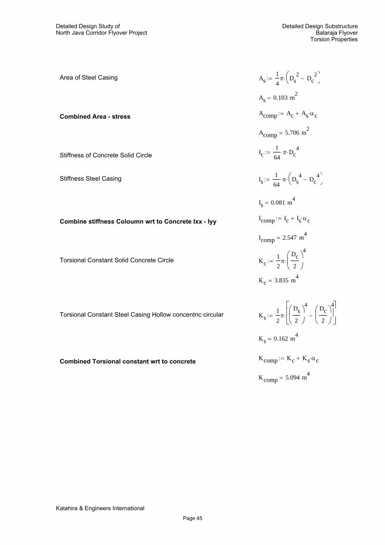
Area of Steel Casing As14π Ds
2 Dc2
−⎛⎝
⎞⎠⋅:=
As 0.103 m2=
Acomp Ac As αc⋅+:=Combined Area - stress
Acomp 5.706 m2=
Ic164
π⋅ Dc4
⋅:=Stiffness of Concrete Solid Circle
Stiffness Steel Casing Is164
π⋅ Ds4 Dc
4−⎛
⎝⎞⎠⋅:=
Is 0.081 m4=
Icomp Ic Is αc⋅+:=Combine stiffness Coloumn wrt to Concrete Ixx - Iyy
Icomp 2.547 m4=
Torsional Constant Solid Concrete Circle Κc12π
Dc2
⎛⎜⎝
⎞⎟⎠
4
⋅:=
Κc 3.835 m4=
Torsional Constant Steel Casing Hollow concentric circular Κs12π
Ds2
⎛⎜⎝
⎞⎟⎠
4 Dc2
⎛⎜⎝
⎞⎟⎠
4
−⎡⎢⎢⎣
⎤⎥⎥⎦
⋅:=
Κs 0.162 m4=
Κcomp Κc Κs αc⋅+:=Combined Torsional constant wrt to concrete
Κcomp 5.094 m4=
Katahira & Engineers International
Page 45
Detailed Design Study ofNorth Java Corridor Flyover Project
Detailed Design SubstructureBalaraja Flyover
Torsion Properties
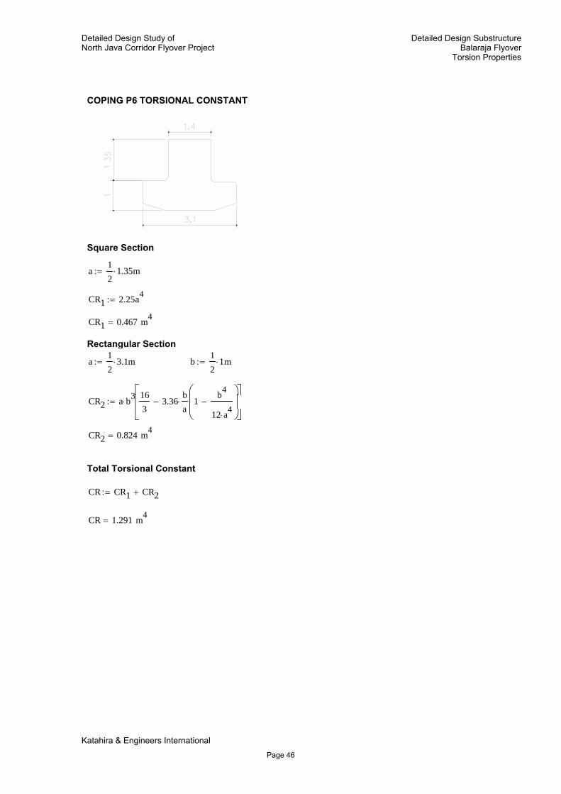
COPING P6 TORSIONAL CONSTANT
Square Section
a12
1.35⋅ m:=
CR1 2.25a4:=
CR1 0.467 m4=
Rectangular Section
a12
3.1⋅ m:= b12
1⋅ m:=
CR2 a b3⋅
163
3.36ba⋅ 1
b4
12 a4⋅
−⎛⎜⎜⎝
⎞⎟⎟⎠
−⎡⎢⎢⎣
⎤⎥⎥⎦
:=
CR2 0.824 m4=
Total Torsional Constant
CR CR1 CR2+:=
CR 1.291 m4=
Katahira & Engineers International
Page 46
Detailed Design Study of North Java Corridor Flyover Project
BALARAJA FLYOVER DETAILED DESIGN
SUBSTRUCTURE
Katahira & Engineers International
2.6 MATERIAL PROPERTIES
Page 47
Detailed Design Study of North Java Corridor Flyover Project
BALARAJA FLYOVER DETAILED DESIGN
SUBSTRUCTURE
Katahira & Engineers International
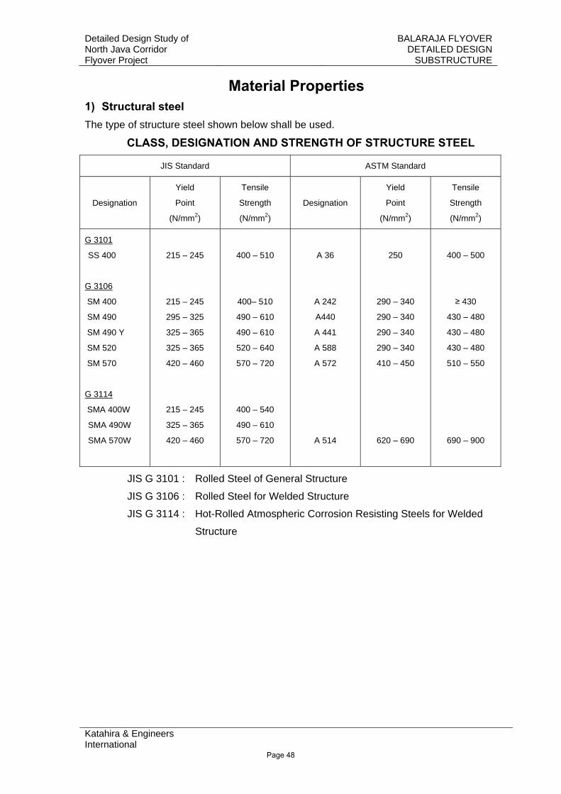
Material Properties 1) Structural steel The type of structure steel shown below shall be used.
CLASS, DESIGNATION AND STRENGTH OF STRUCTURE STEEL
JIS Standard ASTM Standard
Designation
Yield
Point
(N/mm2)
Tensile
Strength
(N/mm2)
Designation
Yield
Point
(N/mm2)
Tensile
Strength
(N/mm2)
G 3101
SS 400
G 3106
SM 400
SM 490
SM 490 Y
SM 520
SM 570
G 3114
SMA 400W
SMA 490W
SMA 570W
215 – 245
215 – 245
295 – 325
325 – 365
325 – 365
420 – 460
215 – 245
325 – 365
420 – 460
400 – 510
400– 510
490 – 610
490 – 610
520 – 640
570 – 720
400 – 540
490 – 610
570 – 720
A 36
A 242
A440
A 441
A 588
A 572
A 514
250
290 – 340
290 – 340
290 – 340
290 – 340
410 – 450
620 – 690
400 – 500
≥ 430
430 – 480
430 – 480
430 – 480
510 – 550
690 – 900
JIS G 3101 : Rolled Steel of General Structure
JIS G 3106 : Rolled Steel for Welded Structure
JIS G 3114 : Hot-Rolled Atmospheric Corrosion Resisting Steels for Welded
Structure
Page 48
Detailed Design Study of North Java Corridor Flyover Project
BALARAJA FLYOVER DETAILED DESIGN
SUBSTRUCTURE
Katahira & Engineers International
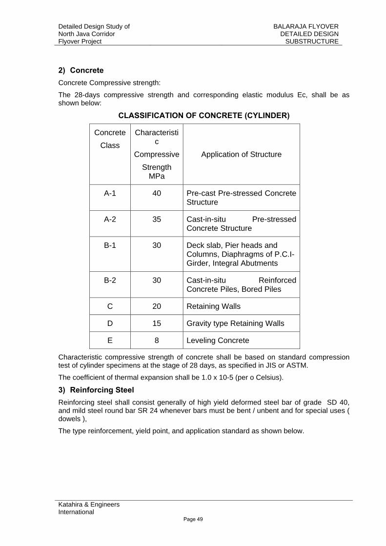
2) Concrete Concrete Compressive strength:
The 28-days compressive strength and corresponding elastic modulus Ec, shall be as shown below:
CLASSIFICATION OF CONCRETE (CYLINDER)
Concrete Class
Characteristic
CompressiveStrength
MPa
Application of Structure
A-1 40 Pre-cast Pre-stressed Concrete Structure
A-2 35 Cast-in-situ Pre-stressed Concrete Structure
B-1 30 Deck slab, Pier heads and Columns, Diaphragms of P.C.I-Girder, Integral Abutments
B-2 30 Cast-in-situ Reinforced Concrete Piles, Bored Piles
C 20 Retaining Walls
D 15 Gravity type Retaining Walls
E 8 Leveling Concrete
Characteristic compressive strength of concrete shall be based on standard compression test of cylinder specimens at the stage of 28 days, as specified in JIS or ASTM.
The coefficient of thermal expansion shall be 1.0 x 10⁻⁵ (per o Celsius).
3) Reinforcing Steel Reinforcing steel shall consist generally of high yield deformed steel bar of grade SD 40, and mild steel round bar SR 24 whenever bars must be bent / unbent and for special uses ( dowels ),
The type reinforcement, yield point, and application standard as shown below.
Page 49
Detailed Design Study of North Java Corridor Flyover Project
BALARAJA FLYOVER DETAILED DESIGN
SUBSTRUCTURE
Katahira & Engineers International
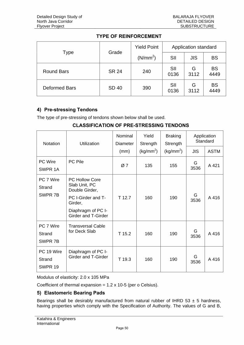
TYPE OF REINFORCEMENT
Yield Point Application standard Type Grade
(N/mm2) SII JIS BS
Round Bars SR 24 240 SII 0136
G 3112
BS 4449
Deformed Bars SD 40 390 SII 0136
G 3112
BS 4449
4) Pre-stressing Tendons The type of pre-stressing of tendons shown below shall be used.
CLASSIFICATION OF PRE-STRESSING TENDONS
Application Standard Notation Utilization
Nominal
Diameter
(mm)
Yield
Strength
(kg/mm2)
Braking
Strength
(kg/mm2) JIS ASTM
PC Wire
SWPR 1A
PC Pile Ø 7 135 155 G
3536 A 421
PC 7 Wire
Strand
SWPR 7B
PC Hollow Core Slab Unit, PC Double Girder,
PC I-Girder and T-Girder,
Diaphragm of PC I-Girder and T-Girder
T 12.7 160 190 G 3536 A 416
PC 7 Wire
Strand
SWPR 7B
Transversal Cable for Deck Slab T 15.2 160 190 G
3536 A 416
PC 19 Wire
Strand
SWPR 19
Diaphragm of PC I-Girder and T-Girder T 19.3 160 190 G
3536 A 416
Modulus of elasticity: 2.0 x 10⁵ MPa
Coefficient of thermal expansion = 1.2 x 10⁻⁵ (per o Celsius).
5) Elastomeric Bearing Pads Bearings shall be desirably manufactured from natural rubber of IHRD 53 ± 5 hardness, having properties which comply with the Specification of Authority. The values of G and B,
Page 50
Detailed Design Study of North Java Corridor Flyover Project
BALARAJA FLYOVER DETAILED DESIGN
SUBSTRUCTURE
Katahira & Engineers International
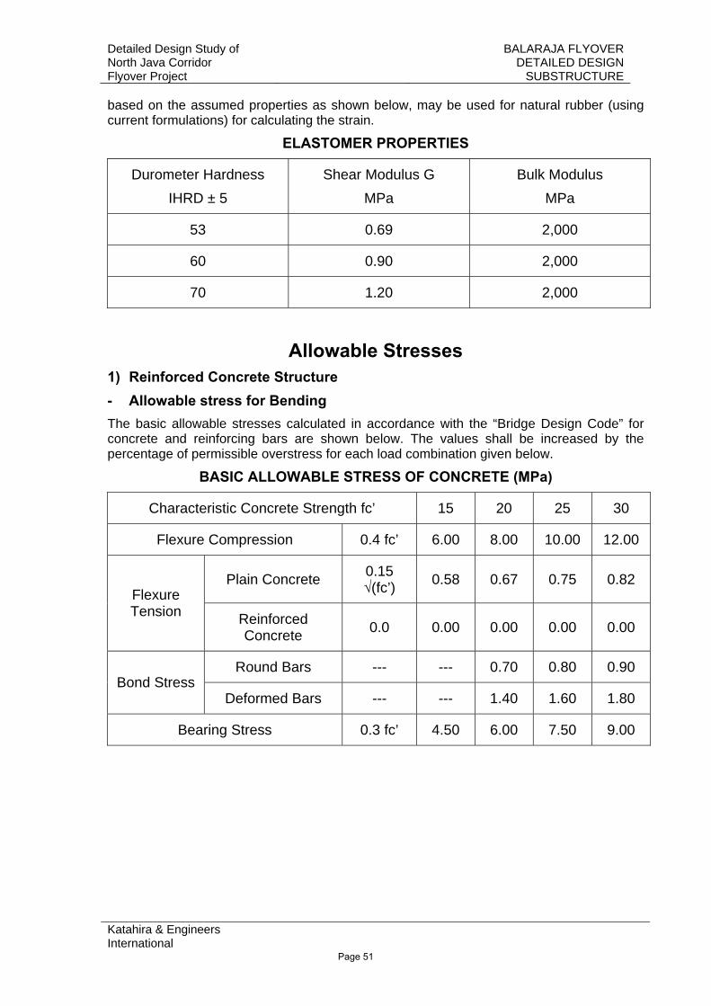
based on the assumed properties as shown below, may be used for natural rubber (using current formulations) for calculating the strain.
ELASTOMER PROPERTIES
Durometer Hardness IHRD ± 5
Shear Modulus G MPa
Bulk Modulus MPa
53 0.69 2,000
60 0.90 2,000
70 1.20 2,000
Allowable Stresses 1) Reinforced Concrete Structure - Allowable stress for Bending The basic allowable stresses calculated in accordance with the “Bridge Design Code” for concrete and reinforcing bars are shown below. The values shall be increased by the percentage of permissible overstress for each load combination given below.
BASIC ALLOWABLE STRESS OF CONCRETE (MPa)
Characteristic Concrete Strength fc’ 15 20 25 30
Flexure Compression 0.4 fc’ 6.00 8.00 10.00 12.00
Plain Concrete 0.15 √(fc’) 0.58 0.67 0.75 0.82
Flexure Tension Reinforced
Concrete 0.0 0.00 0.00 0.00 0.00
Round Bars --- --- 0.70 0.80 0.90 Bond Stress
Deformed Bars --- --- 1.40 1.60 1.80
Bearing Stress 0.3 fc’ 4.50 6.00 7.50 9.00
Page 51
Detailed Design Study of North Java Corridor Flyover Project
BALARAJA FLYOVER DETAILED DESIGN
SUBSTRUCTURE
Katahira & Engineers International
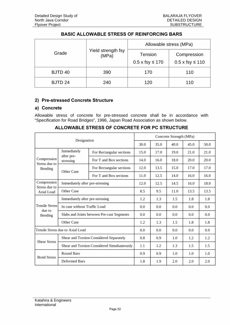
BASIC ALLOWABLE STRESS OF REINFORCING BARS
Allowable stress (MPa)
Grade Yield strength fsy (MPa) Tension
0.5 x fsy ≤ 170 Compression
0.5 x fsy ≤ 110
BJTD 40 390 170 110
BJTD 24 240 120 110
2) Pre-stressed Concrete Structure a) Concrete Allowable stress of concrete for pre-stressed concrete shall be in accordance with “Specification for Road Bridges”, 1996, Japan Road Association as shown below.
ALLOWABLE STRESS OF CONCRETE FOR PC STRUCTURE
30.0 35.0 40.0 45.0 50.0
For Rectangular sections 15.0 17.0 19.0 21.0 21.0
For T and Box sections 14.0 16.0 18.0 20.0 20.0
For Rectangular sections 12.0 13.5 15.0 17.0 17.0
For T and Box sections 11.0 12.5 14.0 16.0 16.0
12.0 12.5 14.5 16.0 18.0
8.5 9.5 11.0 13.5 13.5
1.2 1.3 1.5 1.8 1.8
0.0 0.0 0.0 0.0 0.0
0.0 0.0 0.0 0.0 0.0
1.2 1.3 1.5 1.8 1.8
0.0 0.0 0.0 0.0 0.0
0.8 0.9 1.0 1.2 1.2
Shear and Torsion Considered Simultaneously 1.1 1.2 1.3 1.5 1.5
0.9 0.9 1.0 1.0 1.0
1.8 1.9 2.0 2.0 2.0
Designation
Compression Stress due to
Bending
Immediately after pre-stressing
Other Case
Tensile Stress due to
Bending
Immediately after pre-stressing
In case without Traffic Load
Slabs and Joints between Pre-cast Segments
Other Case
Bond StressRound Bars
Deformed Bars
Concrete Strength (MPa)
Tensile Stress due to Axial Load
Shear StressShear and Torsion Considered Separately
Compression Stress due to Axial Load
Immediately after pre-stressing
Other Case
Page 52
Detailed Design Study of North Java Corridor Flyover Project
BALARAJA FLYOVER DETAILED DESIGN
SUBSTRUCTURE
Katahira & Engineers International
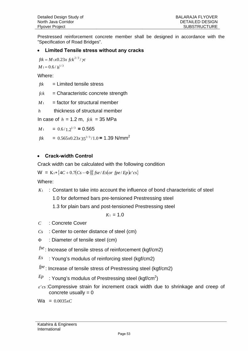
Prestressed reinforcement concrete member shall be designed in accordance with the ”Specification of Road Bridges”.
• Limited Tensile stress without any cracks
hMcfckxxMftk
3/11
3/21
/6.0/23.0
=
= γ
Where: ftk = Limited tensile stress
fck = Characteristic concrete strength
1M = factor for structural member
h thickness of structural member
In case of h = 1.2 m, fck = 35 MPa
1M = 2.1/6.0 3/1 = 0.565
ftk = 0.1/3523.0565.0 3/2xx = 1.39 N/mm2
• Crack-width Control Crack width can be calculated with the following condition W = ( ){ } ( ){ }csEpfpeorEsfseCsC '/ /7.041 εΦ−+∗Κ
Where: 1K : Constant to take into account the influence of bond characteristic of steel
1.0 for deformed bars pre-tensioned Prestressing steel 1.3 for plain bars and post-tensioned Prestressing steel
1K = 1.0 C : Concrete Cover
Cs : Center to center distance of steel (cm)
Φ : Diameter of tensile steel (cm) fse : Increase of tensile stress of reinforcement (kgf/cm2) Es : Young’s modulus of reinforcing steel (kgf/cm2) fpe : Increase of tensile stress of Prestressing steel (kgf/cm2) Ep : Young’s modulus of Prestressing steel (kgf/cm2)
cs'ε :Compressive strain for increment crack width due to shrinkage and creep of concrete usually = 0
Wa = xC0035.0
Page 53
Detailed Design Study of North Java Corridor Flyover Project
BALARAJA FLYOVER DETAILED DESIGN
SUBSTRUCTURE
Katahira & Engineers International
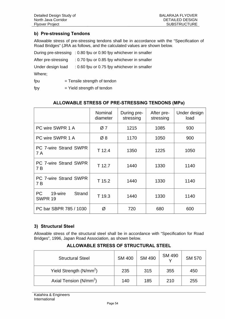
b) Pre-stressing Tendons Allowable stress of pre-stressing tendons shall be in accordance with the “Specification of Road Bridges” (JRA as follows, and the calculated values are shown below.
During pre-stressing : 0.80 fpu or 0.90 fpy whichever in smaller
After pre-stressing : 0.70 fpu or 0.85 fpy whichever in smaller
Under design load : 0.60 fpu or 0.75 fpy whichever in smaller
Where;
fpu = Tensile strength of tendon
fpy = Yield strength of tendon
ALLOWABLE STRESS OF PRE-STRESSING TENDONS (MPa)
Nominal diameter
During pre-stressing
After pre-stressing
Under design load
PC wire SWPR 1 A Ø 7 1215 1085 930
PC wire SWPR 1 A Ø 8 1170 1050 900
PC 7-wire Strand SWPR 7 A T 12.4 1350 1225 1050
PC 7-wire Strand SWPR 7 B T 12.7 1440 1330 1140
PC 7-wire Strand SWPR 7 B T 15.2 1440 1330 1140
PC 19-wire Strand SWPR 19 T 19.3 1440 1330 1140
PC bar SBPR 785 / 1030 Ø 720 680 600
3) Structural Steel Allowable stress of the structural steel shall be in accordance with “Specification for Road Bridges”, 1996, Japan Road Association, as shown below.
ALLOWABLE STRESS OF STRUCTURAL STEEL
Structural Steel SM 400 SM 490 SM 490 Y SM 570
Yield Strength (N/mm2) 235 315 355 450
Axial Tension (N/mm2) 140 185 210 255
Page 54
Detailed Design Study of North Java Corridor Flyover Project
BALARAJA FLYOVER DETAILED DESIGN
SUBSTRUCTURE
Katahira & Engineers International
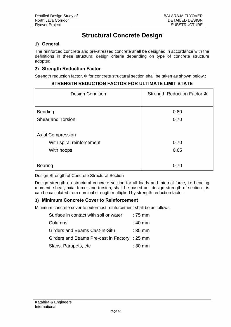
Structural Concrete Design 1) General The reinforced concrete and pre-stressed concrete shall be designed in accordance with the definitions in these structural design criteria depending on type of concrete structure adopted.
2) Strength Reduction Factor Strength reduction factor, Ф for concrete structural section shall be taken as shown below.:
STRENGTH REDUCTION FACTOR FOR ULTIMATE LIMIT STATE
Design Condition Strength Reduction Factor Ф
Bending Shear and Torsion Axial Compression With spiral reinforcement With hoops Bearing
0.80 0.70
0.70 0.65
0.70
Design Strength of Concrete Structural Section
Design strength on structural concrete section for all loads and internal force, i.e bending moment, shear, axial force, and torsion, shall be based on design strength of section , is can be calculated from nominal strength multiplied by strength reduction factor
3) Minimum Concrete Cover to Reinforcement Minimum concrete cover to outermost reinforcement shall be as follows:
Surface in contact with soil or water : 75 mm Columns : 40 mm Girders and Beams Cast-In-Situ : 35 mm Girders and Beams Pre-cast in Factory : 25 mm Slabs, Parapets, etc : 30 mm
Page 55
Detailed Design Study of North Java Corridor Flyover Project
BALARAJA FLYOVER DETAILED DESIGN
SUBSTRUCTURE
Katahira & Engineers International
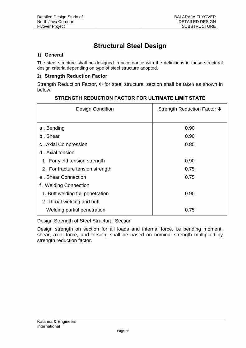
Structural Steel Design 1) General The steel structure shall be designed in accordance with the definitions in these structural design criteria depending on type of steel structure adopted.
2) Strength Reduction Factor Strength Reduction Factor, Ф for steel structural section shall be taken as shown in below.
STRENGTH REDUCTION FACTOR FOR ULTIMATE LIMIT STATE
Design Condition Strength Reduction Factor Ф
a . Bending b . Shear c . Axial Compression d . Axial tension 1 . For yield tension strength 2 . For fracture tension strength e . Shear Connection f . Welding Connection 1. Butt welding full penetration 2 .Throat welding and butt Welding partial penetration
0.90 0.90 0.85
0.90 0.75 0.75
0.90
0.75
Design Strength of Steel Structural Section Design strength on section for all loads and internal force, i.e bending moment, shear, axial force, and torsion, shall be based on nominal strength multiplied by strength reduction factor.
Page 56
Detailed Design Study of North Java Corridor Flyover Project
BALARAJA FLYOVER DETAILED DESIGN
SUBSTRUCTURE
Katahira & Engineers International
3. SOIL PROPERTIES
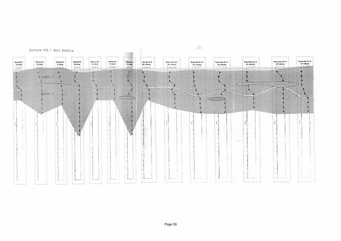
3.1. SOIL PROFILE
3.2. SUMMARY OF SPT’S
3.3. SUMMARY OF UNDISTURBED TESTS
3.4. SUMMARY OF DISTURBED TESTS
3.5. SOIL SPRINGS AND LATERAL BEARING CAPACITY OBTAINED FROM SPT CORRELATIONS
Page 57
Detailed Design Study of North Java Corridor Flyover Project
BALARAJA FLYOVER DETAILED DESIGN
SUBSTRUCTURE
Katahira & Engineers International
3.1 SOIL PROFILE
Page 58
Page 59