Embed Size (px)
Citation preview
1st Summer School on Multiwavelength Astronomy, X and Gamma-ray detectors 1
Detection techniques in X-ray and gamma-ray
astronomyF. Lebrun

1st Summer School on Multiwavelength Astronomy, X and Gamma-ray detectors 2
What it is all about
– Detecting X and gamma-ray photons (0.1 keV – 10 MeV) from a source of interest (sensitivity)
• Counting them (photometry)
• Measuring their energies (spectrometry)
• Measuring individually or collectively their direction (imaging)
• Recording their arrival time (timing)
• Measuring their polarity (polarimetry)
1st Summer School on Multiwavelength Astronomy, X and Gamma-ray detectors 3
Interactions of Photons with Matter
• Photons travel some considerable distance before undergoing a “catastrophic” interaction. All of the photon interactions of interest to us lead to partial or total transfer of the photon energy to electron energy.
• Thus the history of a photon in material is characterized by the sudden disappearance of the photon or by scattering through significant angles with significant energy loss.
• Penetration of photons is governed statistically via interaction probabilities which depend on energy and material.
1st Summer School on Multiwavelength Astronomy, X and Gamma-ray detectors 4
Linear and mass attenuation
• We will look at the three photon interaction types of relevance to this course:
– Photoelectric Absorption
– Compton Scattering
– Pair Production.
• As pointed out above, photon penetration in matter is governed statistically by the probability, per unit distance traveled, that a photon interacts by one physical process (interaction type) or another. This probability is called the linear attenuation coefficient, µ, and has the dimensions of inverse length (eg. cm-1).
• The coefficient µ depends on photon energy and on the material being traversed.
• The mass attenuation coefficient µ /ρ is obtained by dividing µ by the density ρ of the material. It is usually expressed in cm2g-1, and represents the probability of an interaction per g cm-2 of material traversed.

1st Summer School on Multiwavelength Astronomy, X and Gamma-ray detectors 5
Photoelectric absorption
Compton scattering
Pair creation
NIST: http://physics.nist.gov/PhysRefData/Xcom/html/xcom1.html
K edges
µ/ρ

1st Summer School on Multiwavelength Astronomy, X and Gamma-ray detectors 6
Electromagnetic interactions

1st Summer School on Multiwavelength Astronomy, X and Gamma-ray detectors 7
Photoelectric absorption
3- movement of an M shell orbital electron into the K orbital position with the emission of a fluorescent photon.
4- Also shown is the possible alternative, which is the movement of an L orbital electron into the vacancy.
1- incoming photon ejecting the photoelectron
1
3
4
2- The photoelectron direction follows an azimuth sine squared distribution peaking along the polarization direction
2
1st Summer School on Multiwavelength Astronomy, X and Gamma-ray detectors 8
Photoelectic absorption
• The photoelectric process is the predominant mode of interaction for gamma rays (or X-rays) of relatively low energy. The process is also enhanced for absorber materials of high atomic number Z. No single analytic expression is valid for the probability of photoelectric absorption (symbolized τ (tau)) per atom over all ranges of E and Z, but a rough approximation is
τ ~ Z n / E 3
• where the exponent n varies between 4 and 5 over the gamma-ray energy region of interest. This severe dependence of the photoelectric absorption probability on the atomic number of the absorber is a primary reason for the preponderance of high-Z materials (such as lead or tungsten in passive gamma-ray shields or CsI, CdTe or BGO as detectors).
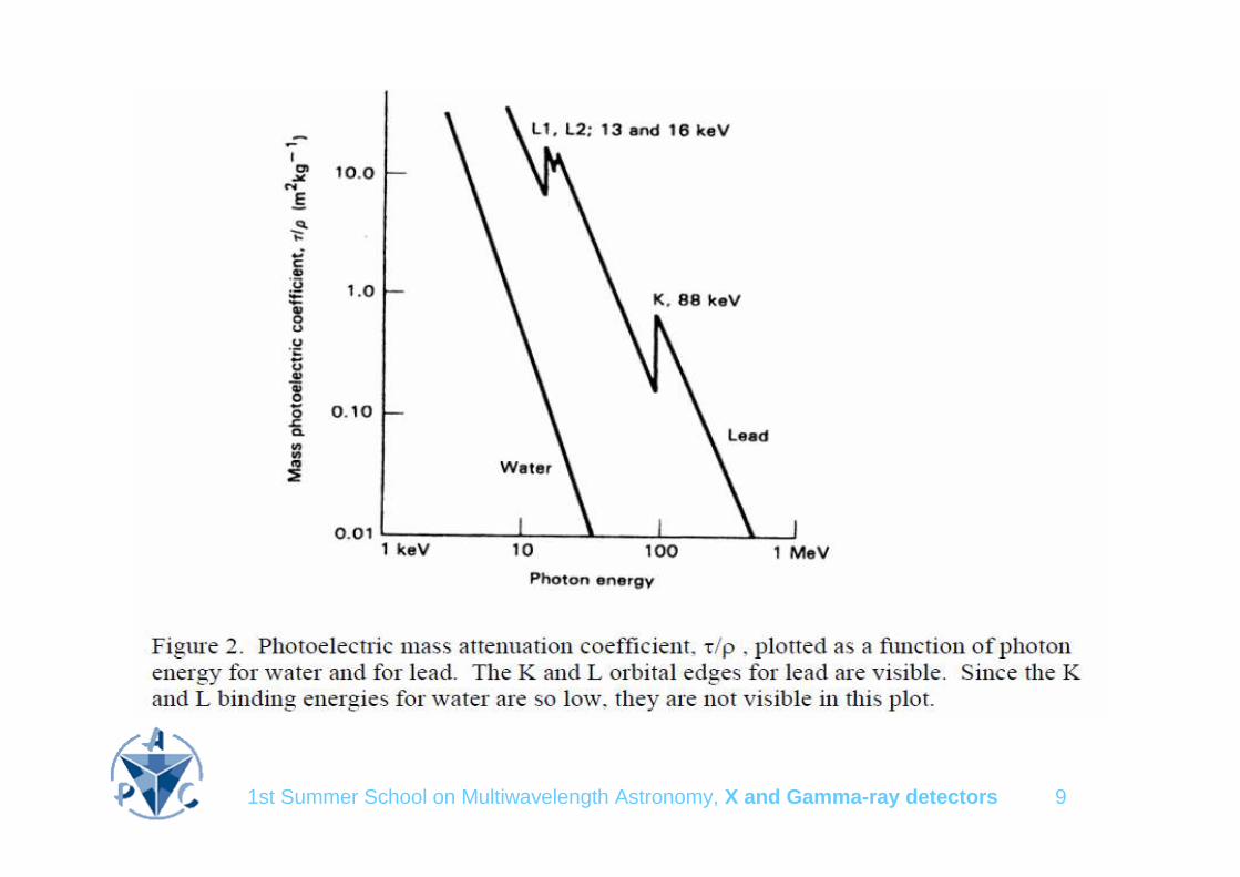
• The photoelectric interaction is most likely to occur if the energy of the incident photon is just greater than the binding energy of the electron with which it interacts. As a result, the plot of the attenuation coefficient as a function of the photon energy is a complicated relationship, with sharp peaks at the binding energies of the various orbital shells and with strong dependence on the atomic number of the atom.
• The photoelectron created in this process, which can sometimes be quite energetic, looses its kinetic energy in exactly the same way as any other light charged particle
1st Summer School on Multiwavelength Astronomy, X and Gamma-ray detectors 9
Photoelectric effect

1st Summer School on Multiwavelength Astronomy, X and Gamma-ray detectors 10
Compton scattering

1st Summer School on Multiwavelength Astronomy, X and Gamma-ray detectors 11
Compton Scattering
• energy and momentum conservation implies:
E’ = E / [1+ E (1-cosθ)], where E = hν / mec2
• Forward scatter: cosθ = 1, E’ = E (no interaction) and Ee= 0
• Backscatter: cosθ = -1, E’ = E / (1+2E) and Ee= 2E2 / (1 + 2E)
• However, the collided electron is generally not free and the link between the quantities E, E’ and cosθ will be affected in proportion of the electron binding energy. The error introduced (often referred to as the Doppler broadening) is important for low energy photons (E<1 MeV) and is larger for higher Z material
• The differential cross section is given by the Kein-Nishina formula:
dσ/dΩ = r02/2 (E’/E)2 (E’/E + E/E’ – sinθ2)

1st Summer School on Multiwavelength Astronomy, X and Gamma-ray detectors 12
Example of spectral response thin CdTe at 60 keV
Full absorption
peak
escape

1st Summer School on Multiwavelength Astronomy, X and Gamma-ray detectors 13
Example of spectral response thin CdTe at 122 keV
Full absorption
peak
escape
BackscatterpeakCompton
front
1st Summer School on Multiwavelength Astronomy, X and Gamma-ray detectors 14
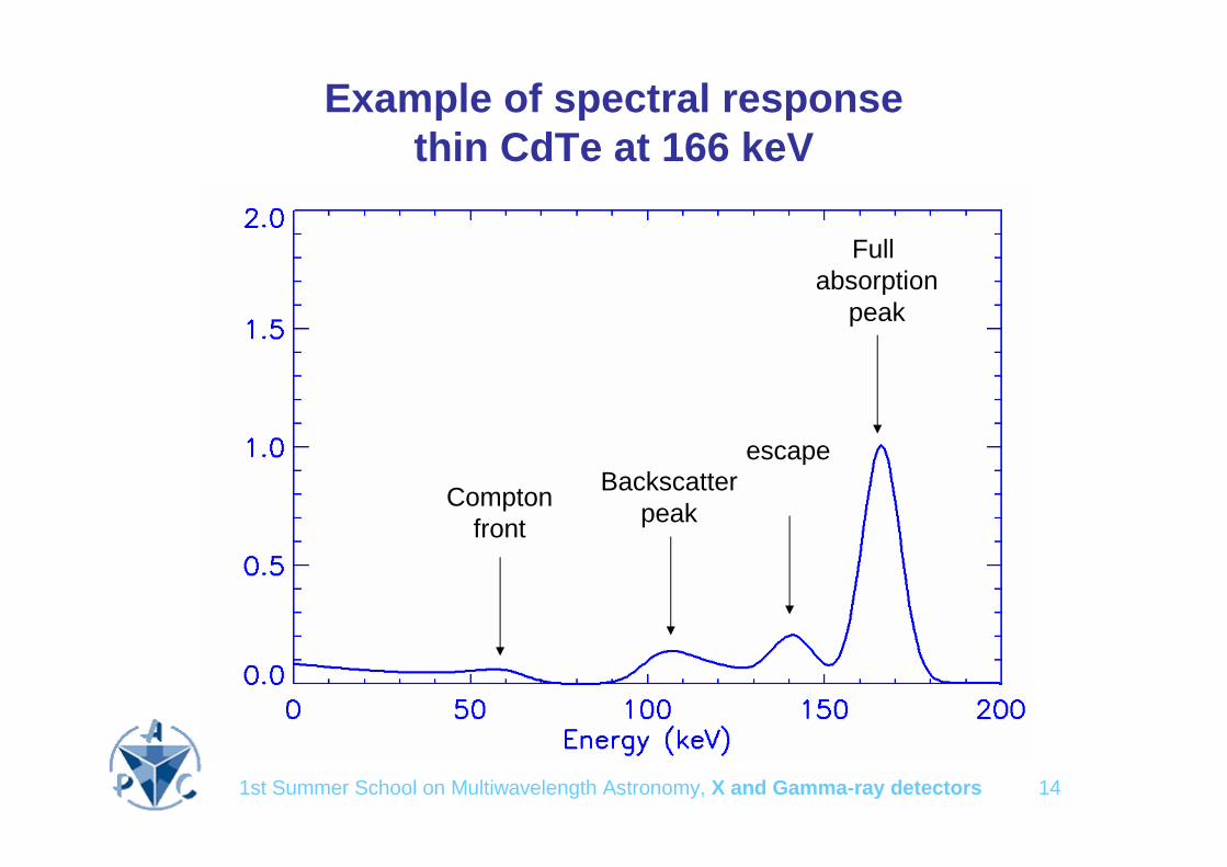
Example of spectral response thin CdTe at 166 keV
Full absorption
peak
escape
Comptonfront
Backscatterpeak
1st Summer School on Multiwavelength Astronomy, X and Gamma-ray detectors 15
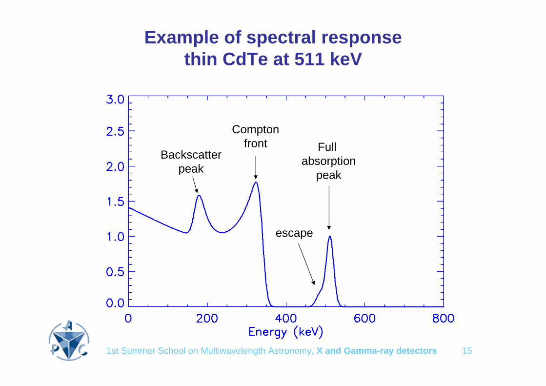
Example of spectral response thin CdTe at 511 keV
Full absorption
peak
escape
Comptonfront
Backscatterpeak

1st Summer School on Multiwavelength Astronomy, X and Gamma-ray detectors 16
Multiple interactions
In a thick target, a series of scatters may occur ending with a photoelectric absorption when the energy of the scattered photon is low enough.
Photoelectric absorption may be followed by fluorescent emission but the fluorescent photon may subsequently be absorbed in the detector
In both cases, if the target is a single detector, the total energy deposited is the energy of the incoming photon exactly as if a single photoelectric absorption had occurred

1st Summer School on Multiwavelength Astronomy, X and Gamma-ray detectors 17
Pair Production
• An energetic photon with an energy in excess of 1.02 MeV passing near the nucleus of an atom, is subjected to strong field effects and may disappear as a photon and reappear as a positive and negative electron pair. Since energy and momentum are not conserved within the system of the disappearing photon and the two emerging electrons, the nucleus is necessary to carry away some energy and momentum.
• Note that the two electrons produced, e- and e+, are not scattered orbital electrons, but are created, de novo, in the energy/mass conversion of the disappearing photon.
• Ee+ ≅ Ee- = ( hν −1.022 ) / 2 (MeV)
• Pair production becomes more likely with increasing photon energy, and the probability (symbolized κ (kappa)) increases with atomic number approximately as Z2.

1st Summer School on Multiwavelength Astronomy, X and Gamma-ray detectors 18
Pair production

1st Summer School on Multiwavelength Astronomy, X and Gamma-ray detectors 19
Polarimetry
Linear polarization affects all the interaction processes, i.e. the azimutal distribution of the interaction products is not flat
– Photoelectric absorption: the K shell electron escape direction follows a sine squared azimuth distribution peaking along the polarization direction
– Compton scatter: the directions of the scattered photon and electron are preferentially (sin2 φ) in a plane orthogonal to the polarization direction
– Pair production: the electronic pair is formed preferentially in the plane of polarization
1st Summer School on Multiwavelength Astronomy, X and Gamma-ray detectors 20
Interactions of electrons with matter
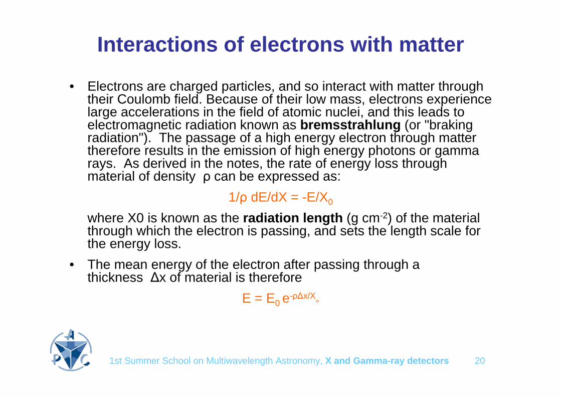
• Electrons are charged particles, and so interact with matter through their Coulomb field. Because of their low mass, electrons experience large accelerations in the field of atomic nuclei, and this leads to electromagnetic radiation known as bremsstrahlung (or "braking radiation"). The passage of a high energy electron through matter therefore results in the emission of high energy photons or gamma rays. As derived in the notes, the rate of energy loss through material of density ρ can be expressed as:
1/ρ dE/dX = -E/X0
where X0 is known as the radiation length (g cm-2) of the material through which the electron is passing, and sets the length scale for the energy loss.
• The mean energy of the electron after passing through a thickness ∆x of material is therefore
E = E0 e-ρ∆x/X°
1st Summer School on Multiwavelength Astronomy, X and Gamma-ray detectors 21
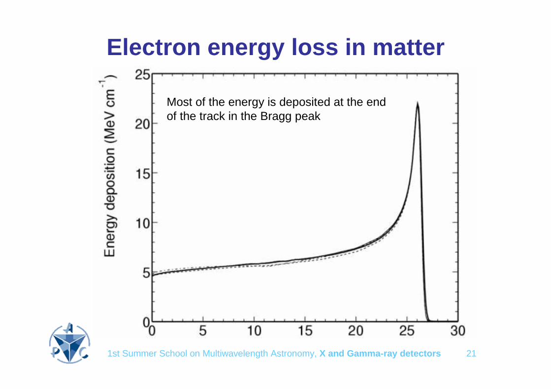
Electron energy loss in matter
Most of the energy is deposited at the end of the track in the Bragg peak

1st Summer School on Multiwavelength Astronomy, X and Gamma-ray detectors 22
Electron tracks in water
1st Summer School on Multiwavelength Astronomy, X and Gamma-ray detectors 23
Where are we ?
• Photons interact with matter and produce photoelectrons
• Photoelectrons loose their energy in ionizing atoms
• Lets speak now about the detector types able to measure this ionisation.
• They are– Gaseous ionisation chambers
– Solid state ionisation chambers (semiconductors)
– Scintillators

1st Summer School on Multiwavelength Astronomy, X and Gamma-ray detectors 24
Ionization chamber• Be a chamber enclosed between parallel electrodes distant by D
and be V the difference of potential between the electrodes
• While a charge q moves by dr in the electric field E=V/D parallel to dr, it produces a work dW = q*E*dr,
• This induces a drop dV = q/C dr/D of the difference of potential between the electrodes. The energy produced by the moving chargeis replenished by the external circuit, which supplies a charge dQ = q dr/D to the anode to keep the applied voltage constant.
• If n charges q are created at the same time in the chamber, the transient voltage-drop, or pulse, due to their drift up to the electrodes will be nq/C, i.e. is a measure of the number of charges created within the chamber.
• It is important to realize that the pulse is not produce by the arrival of the charges to the electrodes but by their transit between the electrodes. If a charge is trapped before arriving to the electrodes, it still contributes to the signal.

1st Summer School on Multiwavelength Astronomy, X and Gamma-ray detectors 25
Charge carrier properties
• Electrons (and holes) subject to a given electric field acquire a velocity proportional to the E field: v = µ E
• The constant of proportionality, µ is called mobility.
• Electrons (and holes) drifting under the effect of an electric field may be trapped.
• Their number decrease exponentially during the transit towards the electrodes so that a lifetime (τ) can be defined.
• µ and τ depends on the detector material, the temperature and may be affected by irradiation.

1st Summer School on Multiwavelength Astronomy, X and Gamma-ray detectors 26
Charge losses
• The term charge refers to the charge of a capacitance during the transit of the charge carriers.
• Loss means that this charge is lower than the number of elementary charges that have been created. This results from
• Charge trapping
• Ballistic losses (discharge of the capacitance during the charge drift time)
i
t
Without trapping
i
Trapping loss
Qt
t
t
ballistic loss
Q
e-+h
h

1st Summer School on Multiwavelength Astronomy, X and Gamma-ray detectors 27
Gaseous Detectors
• When a charged particle passes through a gas, free electrons andpositive ions are produced along its track. If no electric field is applied, ion pairs will recombine, and no signal is produced. By applying different strength fields, different types of detector can be realized.
• If a small field is applied, the electrons drift towards the electrodes. The signal collected is just the original ionization produced. This regime is exploited in an ionization chamber.
• When a larger field is present, the electrons are soon accelerated until they become ionizing themselves. In this way amplification is produced due to secondary ionization. At low gain, the resultant signal remains proportional to the original ionization, and this is known as operation in "proportional mode".

1st Summer School on Multiwavelength Astronomy, X and Gamma-ray detectors 28
Proportional Chambers• In an increased electric field, the electrons are accelerated and
produce secondary ionisation in an avalanche process.
• A gain, or gas multiplication, of 103 to 105 is then possible with a produced signal proportional to the original ionisation. A detector using this technique is known as a proportional counter.
• The simplest way of producing a local region of high electrical field is to use a cylindrical geometry with a very fine central "sense" wire acting as anode. In this way, the amplification region is surrounded by a lower field, and there is no danger of a direct breakdown between the electrodes.
• The maximum of the avalanche occurs very close to the wire. The electrons therefore have a very short drift distance before being collected at the anode, and so contribute little to the induced signal. The ions, however, even though they are more slowly moving (lower mobility), produce a significant signal as they travel through the region of large E.
• Used gas: Argon or Xenon

1st Summer School on Multiwavelength Astronomy, X and Gamma-ray detectors 29
Multiwire Proportional Chambers (MWPCs)
• A development of proportional chambers was to place many detectors in the same gas volume.
• This is done by positioning parallel fine anode wires about 2 mm apart between planar walls which form the cathode.
• If each wire is about 20 microns in diameter, an intense field will be produced in its vicinity, and each will act as an independent detector, if equipped with amplifier and readout electronics.
• The position resolution (perpendicular to the wires) will then be of the order of the wire spacing, though this can be improved to ~0.7 mm if the centroidof the wire pulses is used.
• Resolution in the perpendicular direction can be achieved by two means. – The cathode planes can be divided into independent strips. The centroid of the
induced pulses can then provide a measurement to about 0.1 mm.
– If the anode wires are made of resistive material, then reading out both ends and using charge division provides a resolution of the order of 0.1% of their length.

1st Summer School on Multiwavelength Astronomy, X and Gamma-ray detectors 30
Problems with Proportional Chambers
• Proportional chambers are used very successfully in a large number of experiments. They do, however, suffer from three potential problems: – Mechanical - very fine wires are strung under high mechanical
tension and significant electrostatic forces, and should be kept in their nominal position with a tolerance of the order of 50 microns.
– Physical and chemical breakdown of gases can lead to deposits on the cathode, which in turn can cause electrical discharge within the chamber.
– There are overall rate limitations, due to the build up of space-charge (mainly due to the slowly drifting positive ions).
1st Summer School on Multiwavelength Astronomy, X and Gamma-ray detectors 31
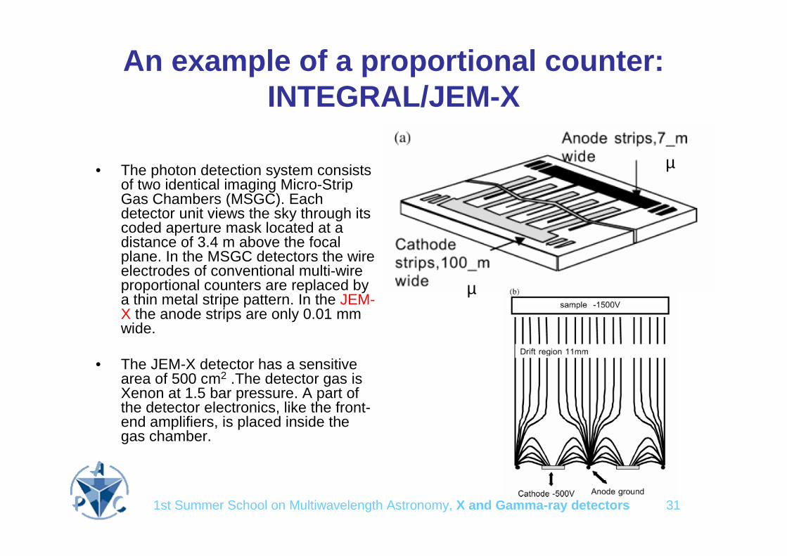
An example of a proportional counter: INTEGRAL/JEM-X
• The photon detection system consists of two identical imaging Micro-Strip Gas Chambers (MSGC). Each detector unit views the sky through its coded aperture mask located at a distance of 3.4 m above the focal plane. In the MSGC detectors the wire electrodes of conventional multi-wire proportional counters are replaced by a thin metal stripe pattern. In the JEM-X the anode strips are only 0.01 mm wide.
• The JEM-X detector has a sensitive area of 500 cm2 .The detector gas is Xenon at 1.5 bar pressure. A part of the detector electronics, like the front-end amplifiers, is placed inside the gas chamber.
µ
µ

1st Summer School on Multiwavelength Astronomy, X and Gamma-ray detectors 32
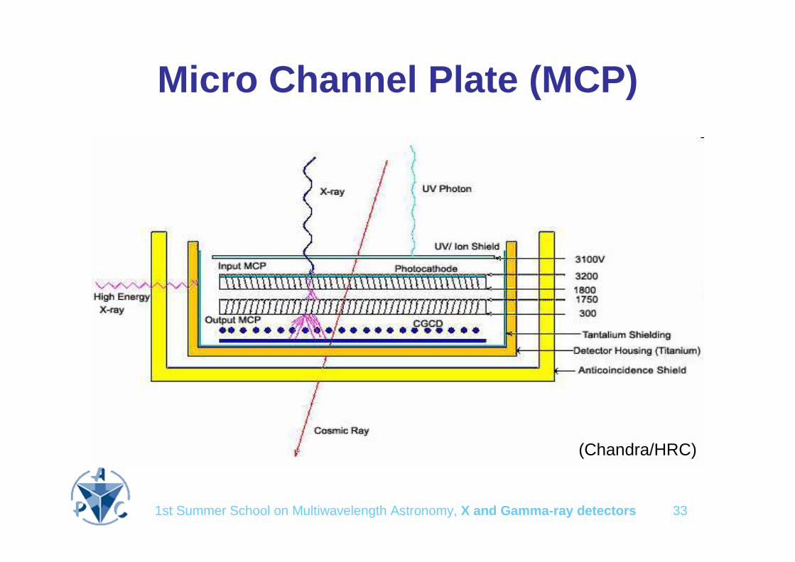
MCPs• A micro-channel plate (MCP) is a sort of planar electron multiplier
• It is a slab made from highly resistive material of typically 2 mm thickness with a regular array of tiny tubes or slots (microchannels) leading from one face to the opposite. The microchannels are typically ~ 10 µ in diameter and spaced apart by ~ 15 µ; they are parallel to each other and often enter the plate at a small angle to the surface (~8°from norm al).
• Under the presence of a strong electric field, a particle or photon that enters one of the channels through a small orifice is guaranteed to hit the wall of the channel (due to the channel being at an angle to the plate). The impact starts a cascade of electrons that propagates through the channel, which amplifies the original signal by several orders of magnitude depending on the electric field strength and the geometry of the micro-channel plate.
• After the cascade, the microchannel takes time to recover (or recharge) before it can detect another signal.
• The electrons exit the channels on the opposite side where they are themselves detected by additional means, often simply a single metal anode measuring total current. In some applications each channel is monitored independently to produce an image (e.g. Chandra/HRC).
1st Summer School on Multiwavelength Astronomy, X and Gamma-ray detectors 33
Micro Channel Plate (MCP)
(Chandra/HRC)

1st Summer School on Multiwavelength Astronomy, X and Gamma-ray detectors 34
Semiconductor detectors• They act as solid state ionization chambers
• Crossing charged particles or photoelectrons ionize atoms along their path
• Since a voltage is applied to the electrodes, the charge carriers (electrons and holes) drift towards the electrodes
• This drift induce a pulse of current
• Semiconductor detectors with a low bandgap require cooling (e.g. Geshould be operated at 80 K)
• The lower is the charge carrier pair creation energy, the better is the energy resolution
p+hv
-
+
e-h
e-
h
-
+

1st Summer School on Multiwavelength Astronomy, X and Gamma-ray detectors 35
Semiconductor detectors
0.610Maximum thickness (cm)
31-3380-5348-523214Z
1.222.11.510.661.12Band gap
4.24.24.422.963.62e-h pair creation energy
0.01204..610002000Hole lifetime (µs)
4002.5731900480Hole mobility (cm2 V-1 s-1)
0.01
8500
0.56
5.31
0.34
5?
GaAs
3.411.670.560.18µ/ ρ (cm2 g-1) @ 100 keV
0.050.100.342.33λ (cm) @ 100 keV
2.81.210001000Electron lifetime (µs)
7095039001350Electron Mobility (cm2 V-1 s-1)
6.36
3
HgI2
50005000 ?Τdec (ns)
5.85.322.33ρ (cm-3)
999TRL
CdTeGeSi

1st Summer School on Multiwavelength Astronomy, X and Gamma-ray detectors 36

1st Summer School on Multiwavelength Astronomy, X and Gamma-ray detectors 37
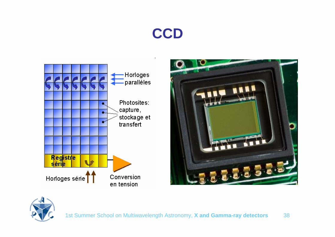
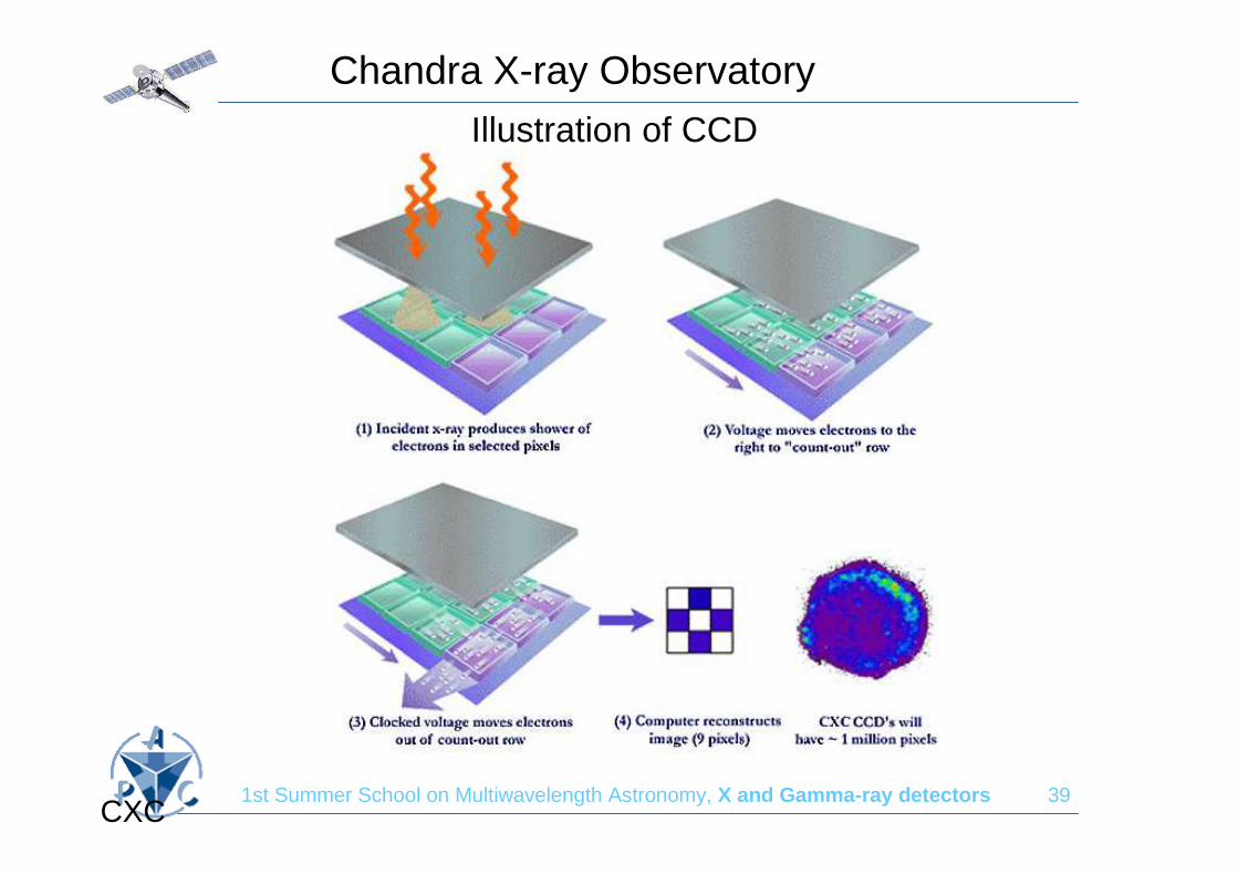
Imaging detectors (N 2 pixels)• CDDs
– Very large number of small pixels (e.g. <50µm)
– Number of readout channels = 1N
– Inconvenient: long reading time (~ 10-4 s)
– Example: XMM/EPIC
• Double Side Stripped detectors (DSSD)– Number of readout channels = 2N
– Inconvenient: capacitance noise
– Example: Fermi
• Pixel detectors– Number of readout channels = N2 (N2 pixels)
– Best energy resolution
– Inconvenient: high power consumption
– Examples: INTEGRAL/ISGRI, SVOM/Eclairs, SIMBOL-X/HED
1st Summer School on Multiwavelength Astronomy, X and Gamma-ray detectors 38
CCD
1st Summer School on Multiwavelength Astronomy, X and Gamma-ray detectors 39
Chandra X-ray Observatory
CXC
Illustration of CCD

1st Summer School on Multiwavelength Astronomy, X and Gamma-ray detectors 40
CDDs reading time
• The advantage is the reduction in electronics (encoders)
• But the reading time is the pain in the neck– Pile-up (affect spectroscopy)– Anticoïncidence systems are barely feasible

1st Summer School on Multiwavelength Astronomy, X and Gamma-ray detectors 41
Pixel cameras
• Each pixel is independent, i.e. has got its own trigger, FEE and read-out
• e.g. INTEGRAL/ISGRI, SIMBOL-X/HED

1st Summer School on Multiwavelength Astronomy, X and Gamma-ray detectors 42
Stripped cameras
Takeda et al., 2007

1st Summer School on Multiwavelength Astronomy, X and Gamma-ray detectors 43
Scintillators• In a scintillator, crossing charged particles or
photoelectrons ionize atoms along their path
• Recombination takes place and visible fluorescent light (scintillation) is emitted
• A fast visible light detector (PMT, Photodiode) collects the light and produce an electric pulse
p+
hv
1st Summer School on Multiwavelength Astronomy, X and Gamma-ray detectors 44
Scintillator properties• Stopping power: expressed in terms of mean
free path
• Light output: governs the energy resolution
• Decay time: in principle an intrinsic property of the crystals but it may be affected by light collection issues
• Refraction index: affects the light collection and therefore the decay time and the energy resolution
• Some scintillators are highly hygroscopic and require an hermetic envelop
1st Summer School on Multiwavelength Astronomy, X and Gamma-ray detectors 45
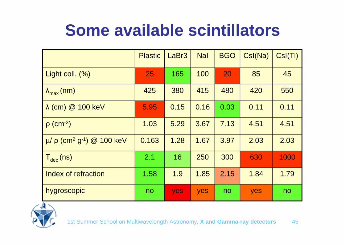
Some available scintillators
no
1.79
1000
2.03
4.51
0.11
550
45
CsI(Tl)
2.033.971.671.280.163µ/ ρ (cm2 g-1) @ 100 keV
0.110.030.160.155.95λ (cm) @ 100 keV
852010016525Light coll. (%)
yes
1.84
630
4.51
420
CsI(Na)
noyesyesnohygroscopic
2.151.851.91.58Index of refraction
300
7.13
480
BGO
250162.1Τdec (ns)
3.675.291.03ρ (cm-3)
415380425λmax (nm)
NaILaBr3Plastic

1st Summer School on Multiwavelength Astronomy, X and Gamma-ray detectors 46
Background
• The notion of background is more tricky than it seems at first sight. What is background for an observer may be signal for another one (e.g. 2 nearby sources, CXB etc.)
• Internal background: it is an effect of the spacecraft high energy particle environment. – Prompt:
• result of the energy loss of electrons, protons or ions through the detectors
• result of the interactions of secondary particles produced by spallation
– Delayed: due to the radioactive decay of unstable isotopes produced during spallation interactions

1st Summer School on Multiwavelength Astronomy, X and Gamma-ray detectors 47
Particle environment
• Radiation belts• South Atlantic Anomaly• Cosmic rays• Solar activity
– Outbursts– Cosmic ray modulation

1st Summer School on Multiwavelength Astronomy, X and Gamma-ray detectors 48
Radiation belts
Units are cm-3 s-1. From Daly E.J. (1988)
Protons Electrons

1st Summer School on Multiwavelength Astronomy, X and Gamma-ray detectors 49
South Atlantic Anomaly (SAA)
• Affects low earth orbit satellites (CGRO, RXTE, Chandra)
• RXTE: The PCA background is a function of time since SAA. There is radioactivation within the instrument, which decays on various timescales. To get an accurate estimate of the amount of activation, the HEXTE particle monitor is used, which remains on even during SAA passages. The PCA instrument itself is off during SAA passes, but the activation persists for several hours afterward.

1st Summer School on Multiwavelength Astronomy, X and Gamma-ray detectors 50
Solar activity
• Cosmic-rays (CR) are “modulated by the solar activity: i.e. the heliosphereexpands and recedes during the solar cycle
• This prevent more or less CR to approach the earth (rigidity cutoff modulation)
Number of sun spots
• As a result the detector internal background is inversely linked to the solar activity if the long lived radioisotopes produced by spallation are not dominant
1st Summer School on Multiwavelength Astronomy, X and Gamma-ray detectors 51
Solar outbursts
• Result of coronal mass ejection (mainly protons)
• Linked directly to solar activity (more frequent at solar maximum)
• Saturates counters of X and gamma-ray detectors (pile-up and dead time effects) and may be dangerous for PMTs
• The heliosphere inflates
• Cosmic-ray density is reduced near the earth
• Internal background of X and gamma-ray detectors may be reduced for a few days !

1st Summer School on Multiwavelength Astronomy, X and Gamma-ray detectors 52
Background components
• Low Earth Orbit
– CDB (FOV)
– Atmospheric emission
• CDB albedo
• CR-induced
– SAA (inclination > 5°)
• Prompt
• delayed
• High Earth Orbit
– CDB (FOV)
– CR-induced (solar modulation)
• Prompt
• delayed
RHESSI, Chandra, SWIFT, Fermi XMM-Newton, INTEGRAL
1st Summer School on Multiwavelength Astronomy, X and Gamma-ray detectors 53
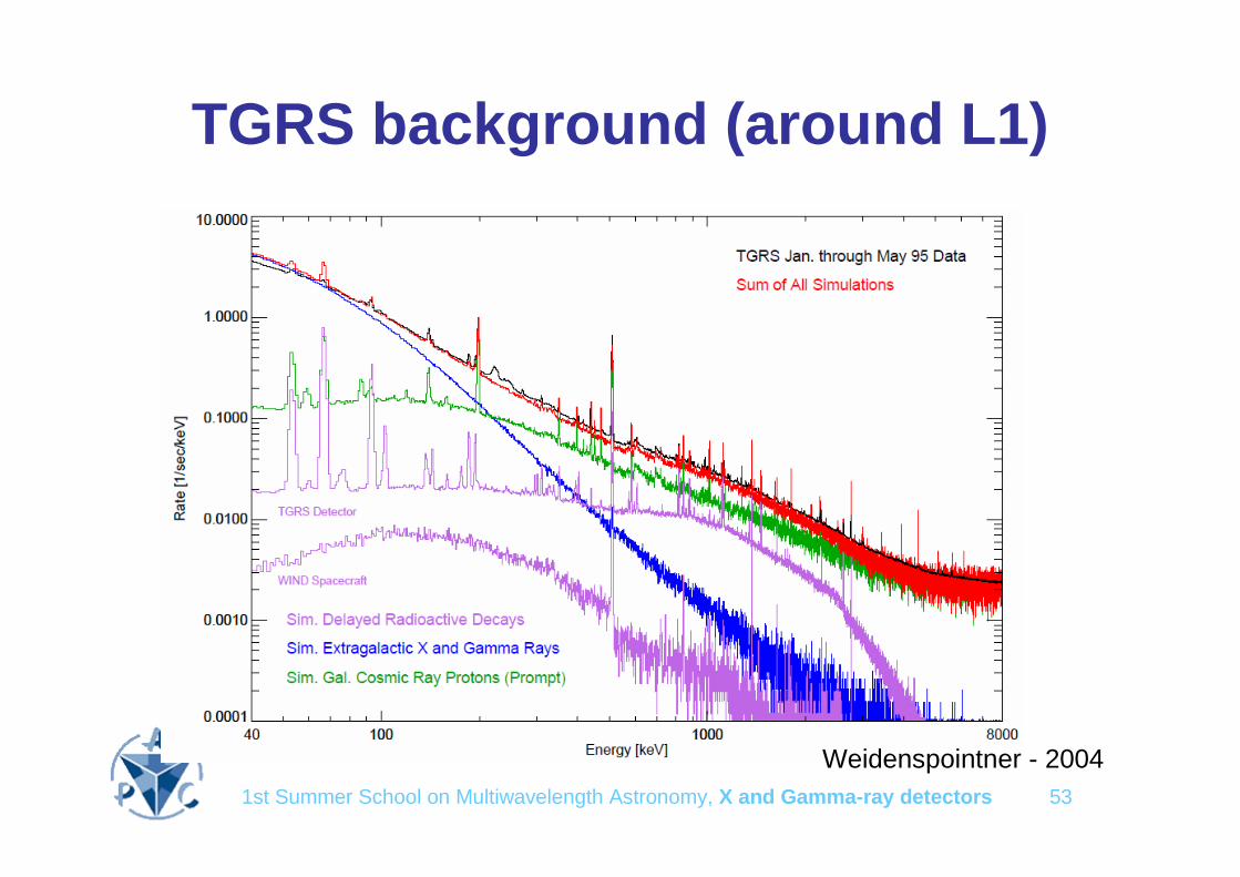
TGRS background (around L1)
Weidenspointner - 2004
1st Summer School on Multiwavelength Astronomy, X and Gamma-ray detectors 54
Background reduction• Passive shields (against CDB and other sources)
• Choice of materials (against delayed instrumental background)
• Choice of orbit: Low Equatorial Orbit (e.g. Bepposax) is best from BKG point of view but– Flip/flop or 50% efficiency
– Available tracking stations
– Batteries
– Not commercially interesting
• Anticoincidence (VETO) systems (against prompt instrumental background) – X-rays (Chandra, Simbol-X)
– Gamma-rays (INTEGRAL)
• Phoswich detectors
1st Summer School on Multiwavelength Astronomy, X and Gamma-ray detectors 55
Anticoïncidence systems (VETO)
• Most of the internal background is due to protons interactions in the detector and its surrounding material (spacecraft)
• Most CR protons are close to the ionisation minimum (1 GeV) and cannot be stopped
• During their material (detector) crossing they leave ample energy deposits that may saturate the electronics (GRANAT/SIGMA, INTEGRAL/PICsIT)
• They can collide with nuclei in the experiment and produce unstable spallation products
• These unstable nuclei decay with gamma-ray emission that can contribute to the background
• If the decay is prompt (less than a few microseconds), the proton passage being easily detected with a simple additional detector, it can provide a VETO signal to prevent the coding of the simultaneous events that triggered the main detector
• Anticoincidence detectors are usually scintillators with relatively poor spectral properties, either plastic (very fast) or high Z (CsI, BGO)

1st Summer School on Multiwavelength Astronomy, X and Gamma-ray detectors 56
Lets take an example: SIMBOL-X

1st Summer School on Multiwavelength Astronomy, X and Gamma-ray detectors 57
The focal plane assembly
• Spectro-imaging system 0.5-100 keV, fast reading
• Full size : 8x8 cm2, 128x128 pixels of 625 µµµµm• Operation at ~ -40°C
Low energydetector (450 µµµµm Silicon)
High energydetector (2 mm Cd(Zn)Te)
Active shielding

1st Summer School on Multiwavelength Astronomy, X and Gamma-ray detectors 58
Low energy detector (MPE/IAAT)
Macro Pixel Detector with integrated DEPFET (WFI)
• Low power consumption• Internal amplification• Active Pixel Sensor type• 100 % filling factor• Adjustable pixel size (50 µµµµm to 1 mm)
• Fast, parallel readout possible
625 µm²0 1000 2000 3000 4000 5000 6000 7000
1
10
100-20 °C
Cou
nts
Energy (eV)
~ 130 eV FWHM @ -20°C
• 4 quadrants in parallel • read-out : 4 µµµµs per row• Full frame in 256 µµµµs• Window mode possible

1st Summer School on Multiwavelength Astronomy, X and Gamma-ray detectors 59
High Energy Detector Basic Brick (CEA/Saclay)
• Electronics : 32 channel front end chip (IdeF-X)
• Hybridization : on going qualification of process, 64 pixels “caliste” modules realized
• Detectors : 2 mm thick pixellated CdTe or CdZnTe crystals
-18° / 400V / CdTeSchottky
1.0 keV
FWHM
1 mm / 64 pixels

1st Summer School on Multiwavelength Astronomy, X and Gamma-ray detectors 60
Phoswich detectorsPrinciple
• Use two scintillators with different decay time, e.g. NaI (250 ns) and CsI (1 µs), readout by a single PMT
• Reject all events with pulse duration longer than the decay time of the fastest scintillator (>500 ns)
Phoswich have proven to be very efficient in reducing the background
hν
p+
hν
1st Summer School on Multiwavelength Astronomy, X and Gamma-ray detectors 61
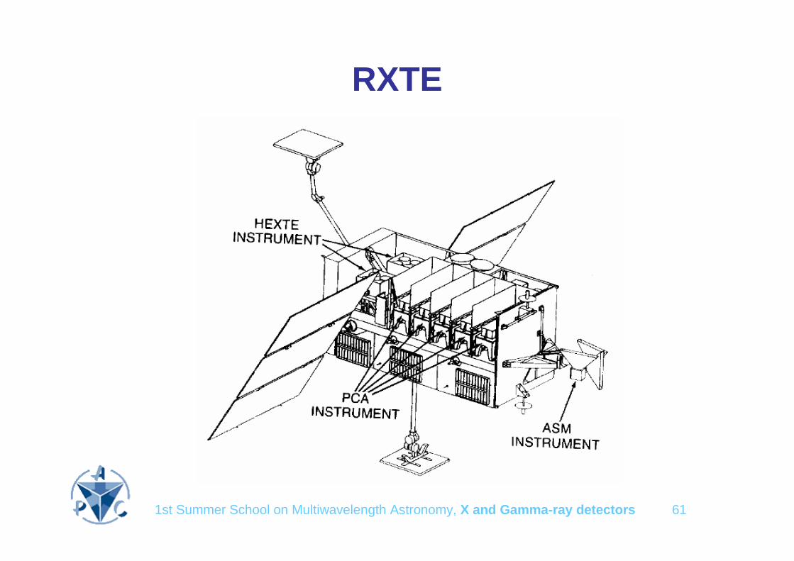
RXTE

1st Summer School on Multiwavelength Astronomy, X and Gamma-ray detectors 62
RXTE/HEXTE
NaI(Tl): 250 nsCsI(Na): 630 ns

1st Summer School on Multiwavelength Astronomy, X and Gamma-ray detectors 63
Compton telescopeEarth limb
Very wide FOVPoor angular resolution (>2°at 511 keV)Good BKG rejectionExcellent polarimeterVery clean spectral responseRequires good and fast imaging spectrometers
511 keV simulation

1st Summer School on Multiwavelength Astronomy, X and Gamma-ray detectors 64
Spectroscopy
In general semiconductors are better spectrometer than scintillators
• X-rays:
– Si (CCDs, STJ)
– Bolometers
• Gamma-rays:
– Cooled Ge (SPI)
– CdTe (SIMBOL-X)
– La Br3 (scintillator !)

1st Summer School on Multiwavelength Astronomy, X and Gamma-ray detectors 65
Gamma-ray experiment calibration
• Requires– X-ray generators (with
fluorescence targets)
– Radioactive sources
– Particle accelerators
• But– Compton scattering in the
surounding materials (e.g. floor, walls etc.)
– Finite distance of radioactive sources
Monte-Carlo simulations

1st Summer School on Multiwavelength Astronomy, X and Gamma-ray detectors 66
Monte-Carlo simulations
• Allows to compute– The sensitive area or ARF (Ancillary
Response Function): sensitive area– The spectral response or RMF (Redistribution
Matrix File)
• Necessary to– Interpolate the experiment response– Simulate trigger logics– Perform tests during flight
1st Summer School on Multiwavelength Astronomy, X and Gamma-ray detectors 67
In-flight calibration
Needed to account for
– Change in the response due to launch stress
– Thermal gradients (vacuum)
– Thermal variations (sun aspect angle)
– Missing ground measurements
– Detector aging
– Effects of irradiation (on detectors and electronics)

1st Summer School on Multiwavelength Astronomy, X and Gamma-ray detectors 68
INTEGRAL/IBIS/ISGRI gain drift
Solar flare

1st Summer School on Multiwavelength Astronomy, X and Gamma-ray detectors 69
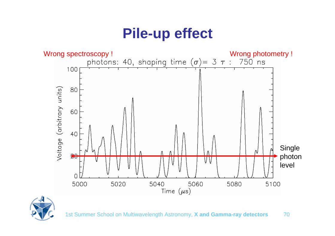
Photometry
• The need is the stability of the detector efficiency or a constant knowledge of it
• Very high fluxes (e.g. magnetars) require fast detectors and fast electronics or many small detectors to avoid pulse pile-up and dead time effects
1st Summer School on Multiwavelength Astronomy, X and Gamma-ray detectors 70
Pile-up effect
Single photon level
Wrong spectroscopy ! Wrong photometry !
1st Summer School on Multiwavelength Astronomy, X and Gamma-ray detectors 71
Dead time
It refers usually to the fraction of time (%) during which an instrument cannot make measurements.
• In some cases or circumstances it could be very large– Very high gamma-ray flux (e.g. bright magnetar outburst)
– Very high particle flux (radiation belts, SAA, Solar outburst)
• It can be due to – a VETO signal triggered by an anticoïncidence system. The rapidity
requirement is on both the main detector and the VETO detector !
– The unavailability of the system that is doing something else; in general not in the wait state, accumulating the signal or encoding it for example. In the very high gamma-ray flux, one way out (at the expense of power consumption) is to increase the number of detectors and decrease their sizes.

1st Summer School on Multiwavelength Astronomy, X and Gamma-ray detectors 72
Timing
High frequency periodic signals (e.g. millisecond pulsars) are usally not a problem for detectors. All you need is:
– a stable clock
– an accurate (~10 km) knowledge of the satellite position
– An accurate knowledge of the detector efficiency (instantaneous photometry)