Embed Size (px)
Citation preview
Vol. 122 (2012) ACTA PHYSICA POLONICA A No. 4
Determination of Stresses and Forces on the Orthodontic
System by Using Numerical Simulation
of the Finite Elements Method
J. Fer£eca, B. Gli²i¢b, I. �¢epanb, E. Markovi¢b, D. Stamenkovi¢b, I. Anºela,J. Fla²kera and R. Rudolfa,c
aUniversity of Maribor, Faculty of Mechanical Engineering, 17 Smetanova Str., 2000 Maribor, SloveniabUniversity of Belgrade, Faculty of Dental Medicine, 8 Dr Suboti¢a Str., 11000 Belgrade, Serbia
cZlatarna Celje d.d., 19 Kersnikova Str., 3000 Celje, Slovenia
(Received January 17, 2012; revised version April 20, 2012; in �nal form July 30, 2012)
This study was addressed to use knowledge about the orthodontic system with numerical simulation ofthe �nite elements method. For the �rst time we simulated the stresses on the orthodontic system and, in thismanner, calculated the orthodontic force on the tooth. A 3D orthodontic model or orthodontic system wasdesigned resembling moderate crowding in the dental arch with all supporting structures. CATIA V5 computersoftware was used to set up a model for the orthodontic system and ABAQUS was used for simulation of thestresses on the orthodontic system. Our attention was focused on the stresses on the tooth lateral incisor and itsperiodontal ligament. The results of the numerical simulation showed complex stresses on the tooth lateral incisorand its periodontal ligament. In this paper there is presented a calculation of the orthodontic force acting on thetooth lateral incisor due to the orthodontic wire. This orthodontic force was calculated from the stresses on thebracket. The calculated orthodontic force was in the area which is considered as the optimal orthodontic force formovement of the tooth.
PACS: 02.70.Dh, 81.40.Jj, 87.10.Kn, 87.19.Rr
1. Introduction
Malocclusion is the misalignment of teeth, or when therelationship between the upper and lower dental archesis incorrect. Malocclusions occur in all three planes ofspace and can a�ect each tooth in all three planes. Totalmalocclusion frequency varies with a mean of 46% [1].Of all malocclusions, crowding is the predominant intra--arch problem in patients seeking orthodontic treatmentin the United States and Western Europe [2, 3].In order to correct malocclusions orthodontic treat-
ment is needed. The preferred treatment option in thecorrection of malocclusions is the utilization of �xed or-thodontic appliances. Contemporary orthodontics relieson the use of �xed orthodontic appliances to solve themisalignment of teeth and bite problems by moving theteeth gradually into the normal position in the dentalarch. The �xed orthodontic appliance consists of brack-ets that are bonded to the teeth, as well as orthodonticwires. When the wire is engaged in the slot of the brack-ets it generates the forces necessary for orthodontic toothmovement [4�6].Each tooth is attached to the alveolar bone by a strong
network of parallel collagen �bres: the periodontal liga-
ment (PDL) is remodelled and renewed constantly dur-ing normal function. PDL has two major components:(1) cellular elements, and (2) the tissue �uid. Both com-ponents play an important role in normal function andallow the orthodontic movements of teeth [7]. The se-quence of events carried out by applying forces withinthe limits of physiological tolerance begins with the de-creased blood �ow through the PDL, followed by theresorption and apposition of the bone. A periodontalligament placed under pressure will result in bone re-sorption, whereas a periodontal ligament under tensionresults in bone formation. Within a few hours of apply-ing a light force, a series of chemical changes in the PDLbegins stimulating the cells to di�erentiate into osteo-clasts (responsible for bone resorption) and osteoblasts(responsible for bone apposition). The bone that op-poses the motion undergoes frontal resorption to allowfor dental displacement, whereas on the opposite side,the stress of the periodontal �bres results in the deposi-tion and production of a new bone. If orthodontic forcesstay light, frontal resorption on one side and appositionon the other will occur at the same rate. When a force ofgreat intensity is applied on the tooth, it causes a vascular
(659)
660 J. Fer£ec et al.
occlusion and cuts the blood supply to the PDL. In thiscase, aseptic necrosis occurs, resulting in an underminingbone resorption that does not start from the dental side,but comes from the alveolar region, causing the tissuedamage, hyalinization and pain. The process of underly-ing resorption is faster and more damaging compared tofrontal resorption [8�12].
In order to prevent undermining resorption light forcesshould be used during orthodontic treatment. The op-timum force used in orthodontic treatment should beenough to produce tooth movement without tissue dam-age and with maximum comfort for the patient. Exces-sive forces can lead to severe pain, damage of the peri-odontal ligament and root resorption [13]. Insu�cientforces extend the duration of the treatment. Deliveringoptimal force levels for controlled tooth movement re-mains of the utmost importance during orthodontic treat-ment. Light continuous orthodontic forces are preferred.The force needed to move the tooth is di�erent for eachtooth and depends on the kind of movement that is re-quired during orthodontic treatment [14]. For example;the force of 10�20 g/cm2 is needed for intrusion, and70�100 g/cm2 is the desirable force for translation [6].Optimum force level for tooth movement usually variesin the range of 0.09 to 0.98 N (9�100 g/cm2).
A variety of wires are used to generate the necessarybiomechanical forces associated with tooth movement,such as: stainless steel; nickel�titanium (NiTi); beta--titanium; and cobalt�chromium. Once the wire is ac-tivated or bent, it is the unloading or deactivating forcesthat produce the orthodontic tooth movement. Withcurrent orthodontic treatment nickel�titanium wires areoften used due to their superior mechanical properties,biocompatibility, ductility, resistance to corrosion, lowerelastic modulus, and special characteristics such as su-perelasticity and shape memory e�ect. The e�ect thatthe wire produces is a summary of properties of the wireitself and geometrical factors. Geometrical factors suchas: the cross-section of the wire (round, rectangular) andthe distance between the brackets, have a great impact onthe force level [9]. All of these factors should be addressedwhen the magnitude of orthodontic force is measured.There is still insu�cient knowledge of the direction, mag-nitude and distribution of the forces applied in orthodon-tic therapy, as well as their e�ect on the tooth and sur-rounding supportive structures. Until recently, much ofthe orthodontic biomechanics literature was restricted to2-dimensional experimental studies of the biomechanicalaspects of orthodontic force systems and, more recently,to 3-dimensional (3D) computer modelling.
There is little evidence regarding 3D experimentalmeasurements and analysis of orthodontic force systems[15�17]. Solutions using numerical methods began af-ter 1970, leading to the development of speci�c soft-ware packages. Research conducted by the �nite ele-ment method (FEM) in dental practice has been relatedmainly to dental implants, stress in periodontal ligamentsand displacements of teeth under the in�uence of exter-
nal forces [7, 18, 19]. The FEM enables the investiga-tion of the biomechanical issues involved in orthodontictreatment. In addition, it stimulates currently increasingscienti�c interest in tooth movement [20]. The develop-ment of a numerical model makes it possible to quantifyand evaluate the e�ects of orthodontic loads applied inorder to achieve tooth movement. One of the main fea-tures of the FEM lies in its potential to analyse complexstructures. In the case of tooth movement, the numericalmodel should resemble the clinical setting, including thetype of malocclusion and choice of brackets, as well asarch wires.Simulation of orthodontic tooth movement with a �xed
orthodontic appliance using FEM can help in the deter-mination of the forces produced by the orthodontic wire.The purpose of this article was to simulate the stresses
on the orthodontic system in the case of moderatelycrowded frontal teeth in the upper dental arch and toquantify the forces applied to teeth when di�erent NiTiwires were engaged in �xed orthodontic appliances.
2. Materials and methods model
The orthodontic 3D model for this study was built us-ing CATIA V5 software. A 3D model of a crowded cen-tral incisor, lateral incisor and canine in the upper dentalarch simulated real malocclusion (Fig. 1).
Fig. 1. Model of moderate crowding in the upper den-tal arch.
A �xed orthodontic appliance was used to simulate theorthodontic treatment in a case with moderate crowd-ing. Metal brackets were bonded to the teeth and wireinserted into the slots. Data for tooth dimensions wereobtained from the dental anatomy literature [21]. Theteeth were modelled using the orthographic views (top,front and side view) of the tooth. The teeth crowns in themodel had the following heights and mesio-distal widthsrespectively: 11.2 mm and 8.6 mm for the central incisor,9.8 mm and 6.6 mm for the lateral incisor and 10.6 mmand 7.6 mm for the canine. The root lengths were: 13 mmfor the central incisor, 13.4 mm for the lateral incisor and16.5 mm for the canine. The position of the teeth in themodel resembled moderate crowding in the upper dental
Determination of Stresses and Forces on the Orthodontic System . . . 661
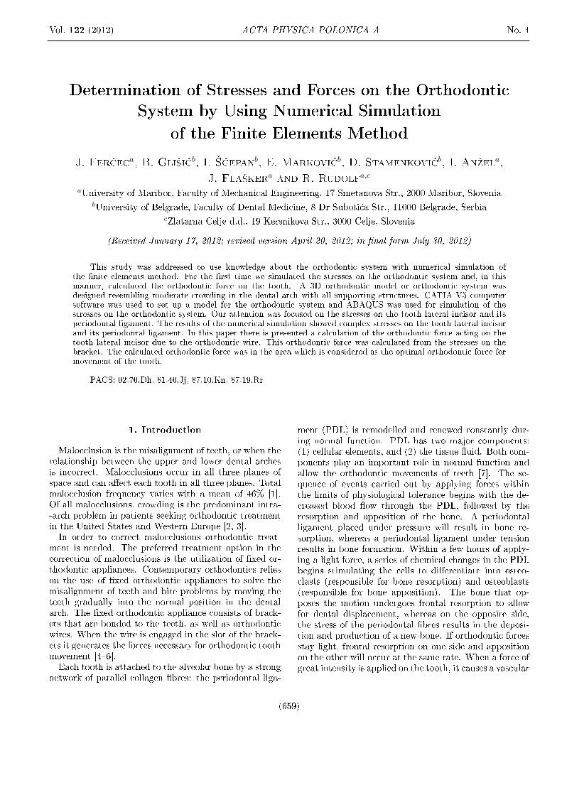
arch. The lateral incisor was moved 4 mm lingually and3 mm gingivally from its normal position in the dentalarch in order to present moderate crowding.
Fig. 2. CAD model of tooth position with boundaryconditions.
A 3D model of the upper frontal teeth was obtained,with the periodontal ligament modelled for the length ofthe whole root (0.25 mm in width) (Fig. 2). Supportivebone was modelled in a 2 mm thick layer, with underlyingcortical bone. The orthodontic NiTi wire was insertedinto the bracket slot of each tooth in the model. For themodel a wire of a diameter of 0.012′′ (0.305 mm) wastaken into consideration.
2.1. Material properties
The 3D model was based on the thesis that all mate-rials are isotropic materials, which means that there aretwo independent material constants. In order to simplifythe model, materials were considered to be homogeneous,meaning that linear and elastic material behaviour in-cluded two constants: Young's modulus and Poisson'sratio. The value of Young's modulus and Poisson's ratiofor the alveolar bone, periodontal ligament, tooth andbracket were taken from literature (Table I) [22].
TABLE I
Young's modulus and Poisson's ratio on separate seg-ments of the orthodontic system.
Linear-elasticmaterial parameters
used for:
Young's modulusof elasticity,E [MPa]
Poisson'sratio
alveolar bone 13800 [18] 0.30 [18]
teeth 20000 [18] 0.30 [18]
periodontal ligament 1 [22] 0.45 [22]
bracket (stainless steel) 180000 0.3
In the numerical simulation that was performed, threedi�erent NiTi orthodontic wires with various modulus ofelasticity (Table II) were used. The purpose of the nu-merical simulation was to determine the initial stresses
TABLE II
Material parameter of wiresfor ABAQUS model.
WireYoung's modulusof austenite,E [MPa]
1. 50000
2. 54000
3. 58000
and, consequently, the force when the wire was insertedinto the slot of the brackets and ligated. Although thebehaviour of NiTi wires in terms of superelasticity iscomplex, we simpli�ed the material properties and theYoung modulus of austenite for numerical analysis wastaken [23]. However, this theory says that when, un-der certain stresses austenitic structures change in themartensitic structure, we can suppose, as in our case,that the stresses on the wire are in the elastic regionof austenite. Data for Young's modulus of austenite forNiTi for various wires are presented in Table II [24]. Inall three wires Poisson's ratio was 0.3 [24].
2.2. Finite element model generation
The constructed model was transferred into theABAQUS/CAE 6.10-1 software for the numerical sim-ulation by the FEM. In our model we performed a staticanalysis. The boundary conditions in our model areshown in Fig. 2. Our model is a �xed one mounted in thealveolar bone. To simplify the numerical calculation we�xed the orthodontic wire rigidly in the bracket of thelateral incisor. Loads were placed on both ends of thewire with the tension load as shown in Fig. 2. With thiskind of load we are closer to the real case. The numericalmodel consists of 86315 �nite elements.
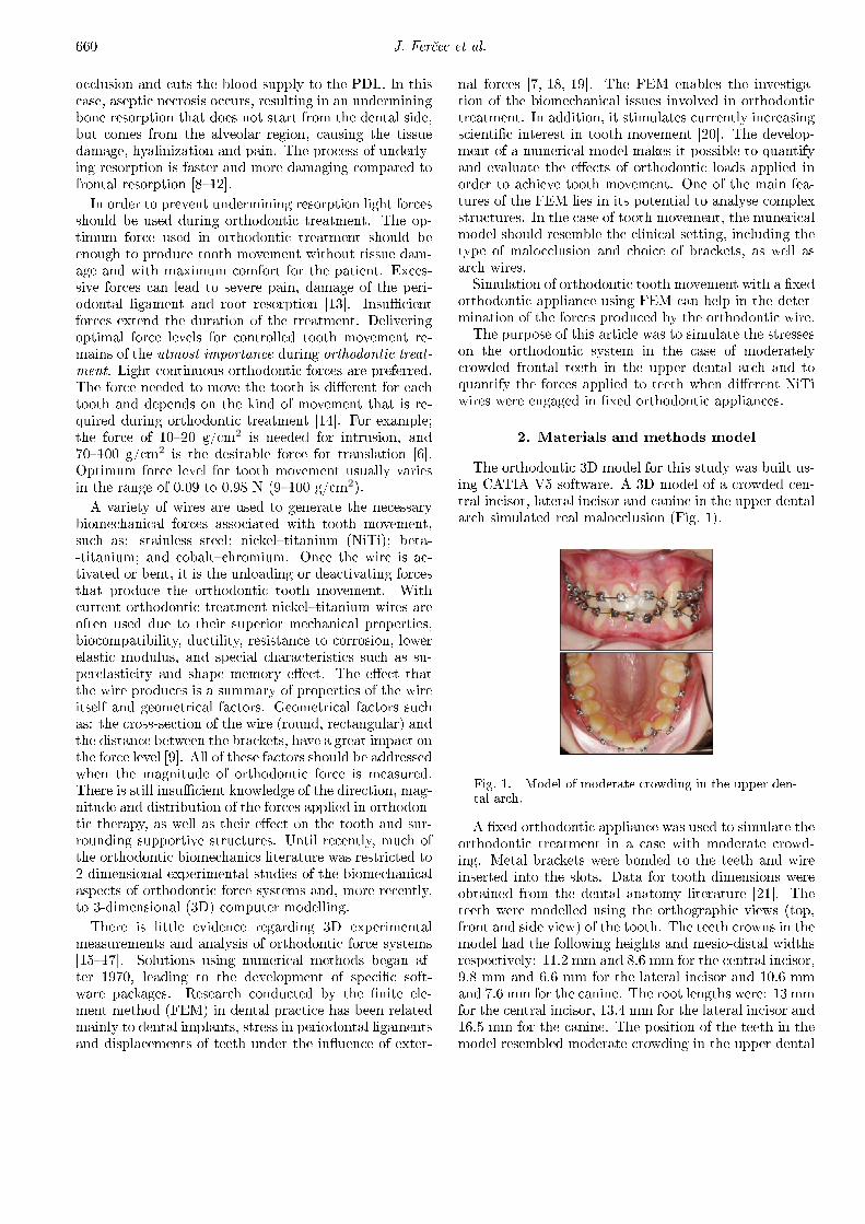
Fig. 3. The �nite-element mesh of the model.
With the automatic mesh generation of parts by tetra-hedral element, the following parts were meshed: alveo-lar bone, PDLs and teeth. The brackets and wire weremeshed by hexahedral �nite elements (Fig. 3). In real
662 J. Fer£ec et al.
orthodontic treatment, especially in the levelling stage,it is desirable for the wire to slide through the slot of thebracket as freely as possible having the least friction [25].In order to choose orthodontic wire wisely it is importantto know the friction properties between the wire and thebracket. Information about these properties in the lit-erature has not been consistent. It is very di�cult todetermine accurately the friction characteristics betweenthe wire and the bracket because the contact conditionsbetween them vary widely. For the friction coe�cientbetween wire (NiTi) and bracket (stainless steel) a valueof 0.3 [26] was taken from the literature. Other con-tacts between segments: alveolar bone-PDL, PDL-tooth,tooth-bracket were rigid.
2.3. Calculation of the force
The tooth was moved through the use of force appliedby the wire inserted into the slot of the bracket. By usingthe FEM the stresses were converted into force.
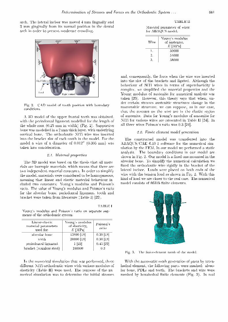
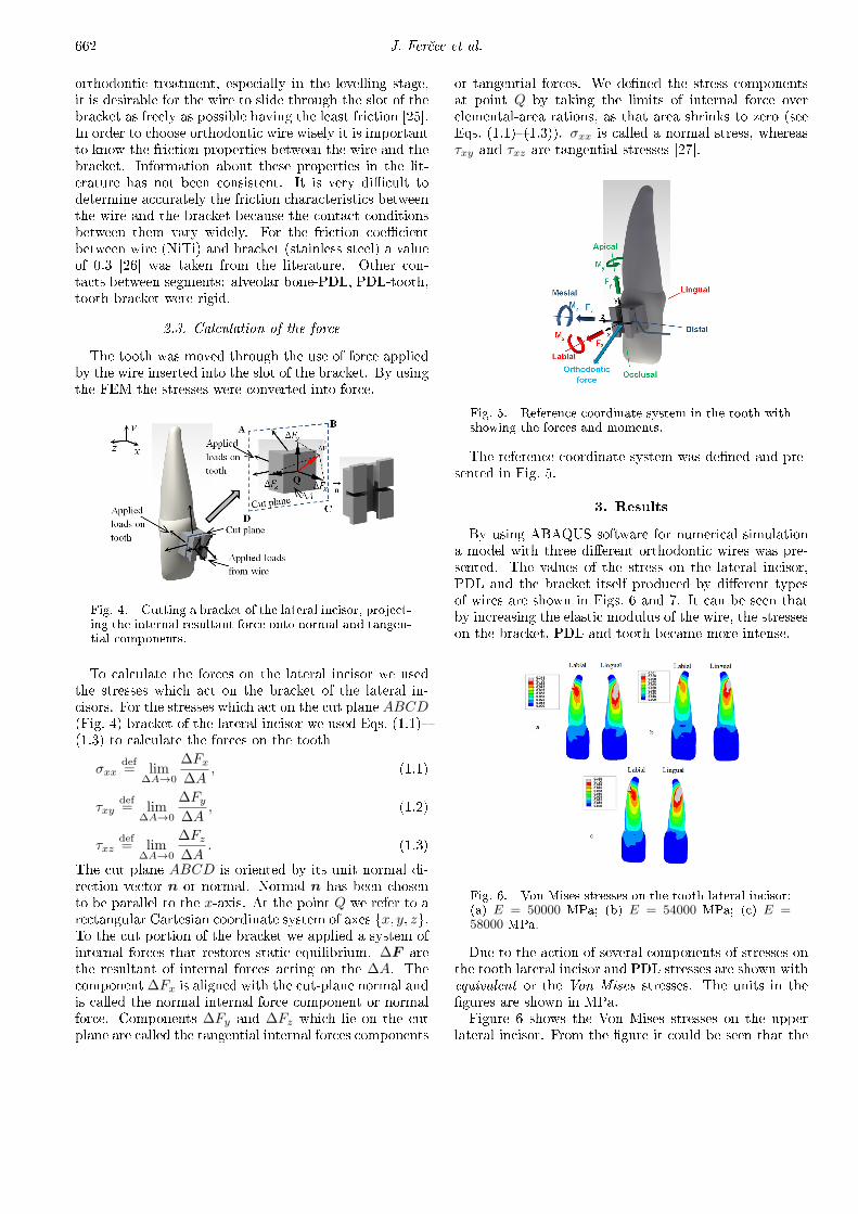
Fig. 4. Cutting a bracket of the lateral incisor, project-ing the internal resultant force onto normal and tangen-tial components.
To calculate the forces on the lateral incisor we usedthe stresses which act on the bracket of the lateral in-cisors. For the stresses which act on the cut plane ABCD(Fig. 4) bracket of the lateral incisor we used Eqs. (1.1)�(1.3) to calculate the forces on the tooth
σxxdef= lim
∆A→0
∆Fx
∆A, (1.1)
τxydef= lim
∆A→0
∆Fy
∆A, (1.2)
τxzdef= lim
∆A→0
∆Fz
∆A. (1.3)
The cut plane ABCD is oriented by its unit normal di-rection vector n or normal. Normal n has been chosento be parallel to the x-axis. At the point Q we refer to arectangular Cartesian coordinate system of axes {x, y, z}.To the cut portion of the bracket we applied a system ofinternal forces that restores static equilibrium. ∆F arethe resultant of internal forces acting on the ∆A. Thecomponent∆Fx is aligned with the cut-plane normal andis called the normal internal force component or normalforce. Components ∆Fy and ∆Fz which lie on the cutplane are called the tangential internal forces components
or tangential forces. We de�ned the stress componentsat point Q by taking the limits of internal force overelemental-area rations, as that area shrinks to zero (seeEqs. (1.1)�(1.3)). σxx is called a normal stress, whereasτxy and τxz are tangential stresses [27].
Fig. 5. Reference coordinate system in the tooth withshowing the forces and moments.
The reference coordinate system was de�ned and pre-sented in Fig. 5.
3. Results
By using ABAQUS software for numerical simulationa model with three di�erent orthodontic wires was pre-sented. The values of the stress on the lateral incisor,PDL and the bracket itself produced by di�erent typesof wires are shown in Figs. 6 and 7. It can be seen thatby increasing the elastic modulus of the wire, the stresseson the bracket, PDL and tooth became more intense.
Fig. 6. Von Mises stresses on the tooth lateral incisor:(a) E = 50000 MPa; (b) E = 54000 MPa; (c) E =58000 MPa.
Due to the action of several components of stresses onthe tooth lateral incisor and PDL stresses are shown withequivalent or the Von Mises stresses. The units in the�gures are shown in MPa.Figure 6 shows the Von Mises stresses on the upper
lateral incisor. From the �gure it could be seen that the
Determination of Stresses and Forces on the Orthodontic System . . . 663
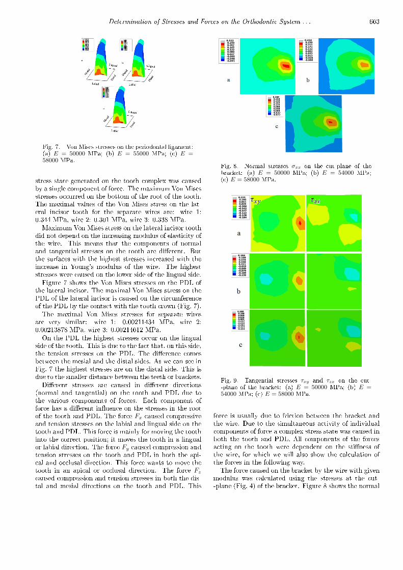
Fig. 7. Von Mises stresses on the periodontal ligament:(a) E = 50000 MPa; (b) E = 55000 MPa; (c) E =58000 MPa.
stress state generated on the tooth complex was causedby a single component of force. The maximum Von Misesstresses occurred on the bottom of the root of the tooth.The maximal values of the Von Mises stress on the lat-eral incisor tooth for the separate wires are: wire 1:0.344 MPa, wire 2: 0.301 MPa, wire 3: 0.338 MPa.Maximum Von Mises stress on the lateral incisor tooth
did not depend on the increasing modulus of elasticity ofthe wire. This means that the components of normaland tangential stresses on the tooth are di�erent. Butthe surfaces with the highest stresses increased with theincrease in Young's modulus of the wire. The higheststresses were caused on the lower side of the lingual side.Figure 7 shows the Von Mises stresses on the PDL of
the lateral incisor. The maximal Von Mises stress on thePDL of the lateral incisor is caused on the circumferenceof the PDL by the contact with the tooth crown (Fig. 7).The maximal Von Mises stresses for separate wires
are very similar: wire 1: 0.00211434 MPa, wire 2:0.00213878 MPa, wire 3: 0.00214612 MPa.On the PDL the highest stresses occur on the lingual
side of the tooth. This is due to the fact that, on this side,the tension stresses on the PDL. The di�erence comesbetween the mesial and the distal sides. As we can see inFig. 7 the highest stresses are on the distal side. This isdue to the smaller distance between the teeth or brackets.Di�erent stresses are caused in di�erent directions
(normal and tangential) on the tooth and PDL due tothe various components of forces. Each component offorce has a di�erent in�uence on the stresses in the rootof the tooth and PDL. The force Fx caused compressiveand tension stresses on the labial and lingual side on thetooth and PDL. This force is mainly for moving the toothinto the correct position; it moves the tooth in a lingualor labial direction. The force Fy caused compression andtension stresses on the tooth and PDL in both the api-cal and occlusal direction. This force wants to move thetooth in an apical or occlusal direction. The force Fz
caused compression and tension stresses in both the dis-tal and mesial directions on the tooth and PDL. This
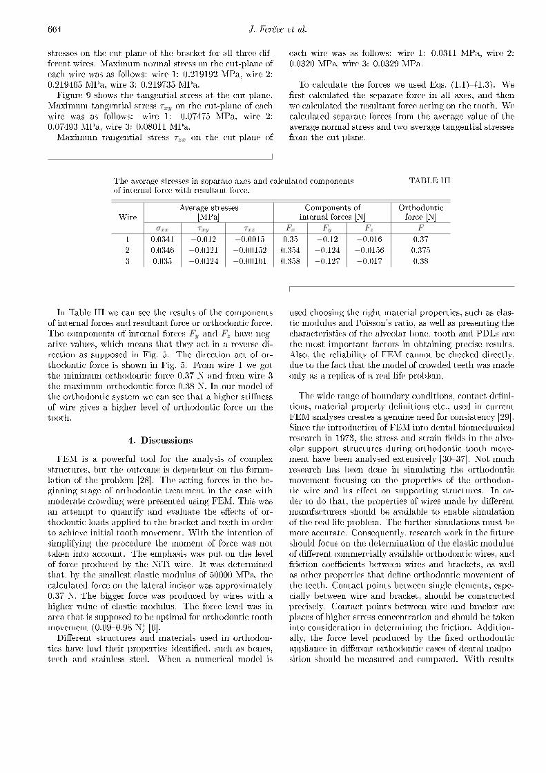
Fig. 8. Normal stresses σxx on the cut-plane of thebracket: (a) E = 50000 MPa; (b) E = 54000 MPa;(c) E = 58000 MPa.
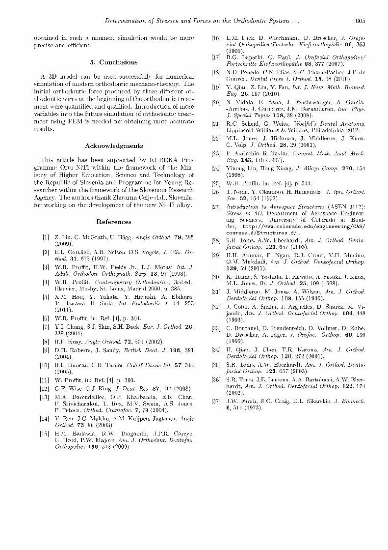
Fig. 9. Tangential stresses τxy and τzx on the cut--plane of the bracket: (a) E = 50000 MPa; (b) E =54000 MPa; (c) E = 58000 MPa.
force is usually due to friction between the bracket andthe wire. Due to the simultaneous activity of individualcomponents of force a complex stress state was caused inboth the tooth and PDL. All components of the forcesacting on the tooth were dependent on the sti�ness ofthe wire, for which we will also show the calculation ofthe forces in the following way.The force caused on the bracket by the wire with given
modulus was calculated using the stresses at the cut--plane (Fig. 4) of the bracket. Figure 8 shows the normal
664 J. Fer£ec et al.
stresses on the cut-plane of the bracket for all three dif-ferent wires. Maximum normal stress on the cut-plane ofeach wire was as follows: wire 1: 0.219192 MPa, wire 2:0.219465 MPa, wire 3: 0.219735 MPa.Figure 9 shows the tangential stress at the cut-plane.
Maximum tangential stress τxy on the cut-plane of eachwire was as follows: wire 1: 0.07475 MPa, wire 2:0.07493 MPa, wire 3: 0.08011 MPa.Maximum tangential stress τzx on the cut-plane of
each wire was as follows: wire 1: 0.0311 MPa, wire 2:0.0320 MPa, wire 3: 0.0329 MPa.
To calculate the forces we used Eqs. (1.1)�(1.3). We�rst calculated the separate force in all axes, and thenwe calculated the resultant force acting on the tooth. Wecalculated separate forces from the average value of theaverage normal stress and two average tangential stressesfrom the cut-plane.
TABLE IIIThe average stresses in separate axes and calculated componentsof internal force with resultant force.
WireAverage stresses
[MPa]Components of
internal forces [N]Orthodonticforce [N]
σxx τxy τxz Fx Fy Fz F
1 0.0341 −0.012 −0.0015 0.35 −0.12 −0.016 0.37
2 0.0346 −0.0121 −0.00152 0.354 −0.124 −0.0156 0.375
3 0.035 −0.0124 −0.00161 0.358 −0.127 −0.017 0.38
In Table III we can see the results of the componentsof internal forces and resultant force or orthodontic force.The components of internal forces Fy and Fz have neg-ative values, which means that they act in a reverse di-rection as supposed in Fig. 5. The direction act of or-thodontic force is shown in Fig. 5. From wire 1 we gotthe minimum orthodontic force 0.37 N and from wire 3the maximum orthodontic force 0.38 N. In our model ofthe orthodontic system we can see that a higher sti�nessof wire gives a higher level of orthodontic force on thetooth.
4. Discussions
FEM is a powerful tool for the analysis of complexstructures, but the outcome is dependent on the formu-lation of the problem [28]. The acting forces in the be-ginning stage of orthodontic treatment in the case withmoderate crowding were presented using FEM. This wasan attempt to quantify and evaluate the e�ects of or-thodontic loads applied to the bracket and teeth in orderto achieve initial tooth movement. With the intention ofsimplifying the procedure the moment of force was nottaken into account. The emphasis was put on the levelof force produced by the NiTi wire. It was determinedthat, by the smallest elastic modulus of 50000 MPa, thecalculated force on the lateral incisor was approximately0.37 N. The bigger force was produced by wires with ahigher value of elastic modulus. The force level was inarea that is supposed to be optimal for orthodontic toothmovement (0.09�0.98 N) [6].Di�erent structures and materials used in orthodon-
tics have had their properties identi�ed, such as bones,teeth and stainless steel. When a numerical model is
used choosing the right material properties, such as elas-tic modulus and Poisson's ratio, as well as presenting thecharacteristics of the alveolar bone, tooth and PDLs arethe most important factors in obtaining precise results.Also, the reliability of FEM cannot be checked directly,due to the fact that the model of crowded teeth was madeonly as a replica of a real life problem.
The wide range of boundary conditions, contact de�ni-tions, material property de�nitions etc., used in currentFEM analyses creates a genuine need for consistency [29].Since the introduction of FEM into dental biomechanicalresearch in 1973, the stress and strain �elds in the alve-olar support structures during orthodontic tooth move-ment have been analysed extensively [30�37]. Not muchresearch has been done in simulating the orthodonticmovement focusing on the properties of the orthodon-tic wire and its e�ect on supporting structures. In or-der to do that, the properties of wires made by di�erentmanufacturers should be available to enable simulationof the real life problem. The further simulations must bemore accurate. Consequently, research work in the futureshould focus on the determination of the elastic modulusof di�erent commercially available orthodontic wires, andfriction coe�cients between wires and brackets, as wellas other properties that de�ne orthodontic movement ofthe teeth. Contact points between single elements, espe-cially between wire and bracket, should be constructedprecisely. Contact points between wire and bracket areplaces of higher stress concentration and should be takeninto consideration in determining the friction. Addition-ally, the force level produced by the �xed orthodonticappliance in di�erent orthodontic cases of dental malpo-sition should be measured and compared. With results
Determination of Stresses and Forces on the Orthodontic System . . . 665
obtained in such a manner, simulation would be moreprecise and e�cient.
5. Conclusions
A 3D model can be used successfully for numericalsimulation of modern orthodontic mechano-therapy. Theinitial orthodontic force produced by three di�erent or-thodontic wires at the beginning of the orthodontic treat-ment were quanti�ed and quali�ed. Introduction of morevariables into the future simulation of orthodontic treat-ment using FEM is needed for obtaining more accurateresults.
Acknowledgments
This article has been supported by EUREKA Pro-gramme Orto-NiTi within the framework of the Min-istry of Higher Education, Science and Technology ofthe Republic of Slovenia and Programme for Young Re-searcher within the framework of the Slovenian ResearchAgency. The authors thank Zlatarna Celje d.d., Slovenia,for working on the development of the new Ni�Ti alloy.
References
[1] Z. Liu, C. McGrath, U. Hägg, Angle Orthod. 79, 585(2009).
[2] E.L. Gottlieb, A.H. Nelson, D.S. Vogels, J. Clin. Or-thod. 31, 675 (1997).
[3] W.R. Pro�t, H.W. Fields Jr., L.J. Moray, Int. J.Adult. Orthodon. Orthognath. Surg. 13, 97 (1998).
[4] W.R. Pro�t, Contemporary Orthodontics, 3rd.ed.,Elsevier, Mosby; St. Louis, Madrid 2000, p. 385.
[5] X.M. Hou, Y. Yahata, Y. Hayashi, A. Ebihara,T. Hanawa, H. Suda, Int. Endodontic J. 44, 253(2011).
[6] W.R. Pro�t, in: Ref. [4], p. 304.
[7] Y.I. Chang, S.J. Shin, S.H. Baek, Eur. J. Orthod. 26,339 (2004).
[8] R.P. Kusy, Angle Orthod. 72, 501 (2002).
[9] D.H. Roberts, J. Sandy, British Dent. J. 196, 391(2004).
[10] R.L. Duncan, C.H. Turner, Calcif Tissue Int. 57, 344(2005).
[11] W. Pro�t, in: Ref. [4], p. 303.
[12] G.E. Wise, G.J. King, J. Dent. Res. 87, 414 (2008).
[13] M.A. Darendeliler, O.P. Kharbanda, E.K. Chan,P. Srivicharnkul, T. Rex, M.V. Swain, A.S. Jones,P. Petocz, Orthod. Craniofac. 7, 79 (2004).
[14] Y. Ren, J.C. Maltha, A.M. Kuijpers-Jagtman, AngleOrthod. 73, 86 (2003).
[15] H.M. Badawia, R.W. Toogoodb, J.P.R. Careyc,G. Heod, P.W. Majore, Am. J. Orthodont. Dentofac.Orthopedics 136, 518 (2009).
[16] L.M. Fuck, D. Wiechmann, D. Drescher, J. Orofa-cial Orthopedics/Fortschr. Kieferorthopädie 66, 363(2005).
[17] B.G. Lapatki, O. Paul, J. Orofacial Orthopedics/Fortschritte Kieferorthopädie 68, 377 (2007).
[18] N.D. Penedo, C.N. Elias, M.C. ThoméPachec, J.P. deGouvêa, Dental Press J. Orthod. 15, 98 (2010).
[19] Y. Qian, Z. Liu, Y. Fan, Int. J. Num. Meth. Biomed.Eng. 26, 157 (2010).
[20] N. Vidala, E. Asua, J. Feuchtwanger, A. Garcia--Arribas, J. Gutierrez, J.M. Barandiaran, Eur. Phys.J. Special Topics 158, 39 (2008).
[21] R.C. Scheid, G. Weiss, Woelfel's Dental Anatomy,Lippincott Williams & Wilkins, Philadelphia 2012.
[22] M.L. Jones, J. Hickman, J. Middleton, J. Knox,C. Volp, J. Orthod. 28, 29 (2001).
[23] F. Auricchio, R. Taylor, Comput. Meth. Appl. Mech.Eng. 143, 175 (1997).
[24] Yinong Liu, Hong Xiang, J. Alloys Comp. 270, 154(1998).
[25] W.R. Pro�t, in: Ref. [4], p. 344.
[26] T. Noda, Y. Okamoto, H. Hamanaka, J. Jpn. Orthod.Soc. 52, 154 (1993).
[27] Introduction to Aerospace Structures (ASEN 3112);Stress in 3D, Department of Aerospace Engineer-ing Sciences, University of Colorado at Boul-der, http://www.colorado.edu/engineering/CAS/courses.d/Structures.d/ .
[28] S.R. Toms, A.W. Eberhardt, Am. J. Orthod. Dento-facial Orthop. 123, 657 (2003).
[29] H.H. Ammar, P. Ngan, R.J. Crout, V.H. Mucino,O.M. Mukdadi, Am. J. Orthod. Dentofacial Orthop.139, 59 (2011).
[30] K. Tanne, S. Yoshida, T. Kawata, A. Sasaki, J. Knox,M.L. Jones, Br. J. Orthod. 25, 109 (1998).
[31] J. Middleton, M. Jones, A. Wilson, Am. J. Orthod.Dentofacial Orthop. 109, 155 (1996).
[32] J. Cobo, A. Sicilia, J. Arguelles, D. Suarez, M. Vi-jande, Am. J. Orthod. Dentofacial Orthop. 104, 448(1993).
[33] C. Bourauel, D. Freudenreich, D. Vollmer, D. Kobe,D. Drescher, A. Jager, J. Orofac. Orthop. 60, 136(1999).
[34] H. Qian, J. Chen, T.R. Katona, Am. J. Orthod.Dentofacial Orthop. 120, 272 (2001).
[35] S.R. Toms, A.W. Eberhardt, Am. J. Orthod. Dento-facial Orthop. 123, 657 (2003).
[36] S.R. Toms, J.E. Lemons, A.A. Bartolucci, A.W. Eber-hardt, Am. J. Orthod. Dentofacial Orthop. 122, 174(2002).
[37] J.W. Farah, R.G. Craig, D.L. Sikarskie, J. Biomech.6, 511 (1973).