Embed Size (px)
Citation preview
1
Determination of Stresses at Inclusions in Single Crystal Superalloy using
HR-EBSD, Crystal Plasticity and Inverse Eigenstrain Analysis
M.E. Kartal
1,*, R. Kiwanuka
1 and F. P. E. Dunne
2
1Department of Engineering Science, University of Oxford, Parks Road, Oxford OX1 3PJ,
UK
2Department of Materials, Imperial College, London SW7 2AZ
Abstract
The complementary techniques of high-resolution electron backscatter diffraction (HR-
EBSD), crystal plasticity finite element modelling and the inverse method of eigenstrain are
utilized for evaluating stresses resulting from the mismatch in thermal expansivities of a
nickel single crystal containing a carbide particle. The EBSD method is employed to measure
the complete residual elastic strain tensor on the free surface of the nickel matrix around a
particular carbide particle. With these experimental results, the 3D inverse problem of
eigenstrain is reconstructed to determine the complete residual stresses local to the particle at
the sub-surface of the sample. A gradient-enhanced crystal plasticity finite element (CPFE)
model has been developed for the same sample and loading conditions, and detailed
comparisons of the eigenstrain and CPFE predicted stresses at the sub-surface of the sample
are presented. In addition, free-surface residual elastic strains measured by HR-EBSD and
predicted by the CPFE model are compared. Free-surface results show very good agreement,
but some differences are apparent for sub-surface results. The eigenstrain technique relies on
the assumption of uniform plastic strain in the direction normal to the free surface, and the
CPFE approach provides an assessment of this assumption. The free-surface effects of 3D
particle depth are also assessed.
Keywords: Residual stress; eigenstrain; HR-EBSD; crystal plasticity, nickel superalloys
*Corresponding author. Tel.: +44 1865 283489 E-mail: [email protected]
2
1. Introduction
Knowledge of the residual stresses which exist at key microstructural features in structural
materials plays an increasingly pivotal role in component lifing methodologies. Fatigue crack
nucleation, for example, is known to occur preferentially at second-phase particles (SPPs) in
aluminium alloys [1], and at agglomerates in powder metallurgy processed nickel alloys [2]
which act as stress raisers and the sites of highly localised slip. Modelling methods
appropriate for the microstructural level such as crystal plasticity and discrete dislocation
techniques are increasingly being employed in order to determine stress and plastic strain at
key fatigue-inducing microstructural features (grain boundaries, triple junctions, twins, SPPs)
[3]. Such models are growing in their sophistication providing additional microstructure-level
information such as lattice rotations and curvatures and densities of geometrically necessary
dislocations [3]. There is, therefore, great need for rigorously tested and validated models and
a powerful experimental technique which can facilitate this is high resolution EBSD [4].
However, the technique is generally confined to free-surface measurement, albeit with the
current resolution (tens of nanometers) enabling accurate elastic lattice strain (and hence
stress) and rotation to be calculated [5]. Recently, highly successful 3D HR-EBSD has been
reported [6], but this remains a destructive technique, and indeed the serial sectioning process
leads to a change of stress state from what originally existed sub-surface to one which
becomes approximately plane stress as material is machined away. Hence, the HR-EBSD-
measured strains are those corresponding to free-surface, plane stress conditions rather than
to those which existed before the serial sectioning process. Often, it is of more importance to
gain knowledge not of free-surface microstructural stress state, but that which occurs sub-
surface at the key microstructural features. For this reason, microstructural inverse
eigenstrain techniques have been established [7] for a given class of problem which utilise the
3
measurement of free-surface elastic strain from HR-EBSD in order to establish full field 3D
(sub-surface) stress distributions. The technique necessitates use of the commonly adopted
assumption of invariant sub-surface eigenstrain distribution (often meaning plastic strain),
and it is important that the validity of this simplification be tested. Previous work [12] also
employed crystal plasticity modelling to assess the agreement between HR-EBSD
measurements of free surface strains and crystal plasticity model predictions. However, this
work did not address the eigenstrain technique nor assess the role of the particle depth on
free-surface strain distribution. Hence, the aim of this work is multifold. Firstly, we aim to
demonstrate an independent validation of the recent development [7] that extends the
capability of the inverse problem of eigenstrain to determine residual stresses at sub-surface
single-crystal nickel – carbide particle interfaces. Secondly, we investigate the accuracy of
microstructure-based crystal plasticity modelling in capturing with fidelity the HR-EBSD-
measured elastic lattice strains local to the single crystal – SPP interface, and thirdly, the
effect of the sub-surface particle depth on the free-surface HR-EBSD-measured elastic strains
is investigated. In the presentation, length-scale–enhanced crystal plasticity finite element
modelling is introduced to simulate the single-crystal-particle material subjected to cooling
from 820 °C to 20 °C from a nominally stress-free state thus causing the development of
thermal mismatch strains as a result of the differing thermal expansivities of the Ni matrix
and the carbide particle. Detailed comparisons between 3D crystal model predictions and
HR-EBSD free-surface measurements are firstly presented. This is then followed by an
analysis of the sub-surface stresses developed local to the particle obtained from the
eigenstrain technique which are assessed against the crystal plasticity model predictions. An
assessment is then presented of the key assumptions utilized in the eigenstrain technique.
Finally, we examine the role of the particle out-of-plane length on influencing the free-
surface strain and stress distributions measured using HR-EBSD.
4
2. Experimental Background
The material used in this study (supplied by Rolls-Royce plc) is a high tantalum and niobium-
containing variant of the nickel superalloy MAR-M-002, which is widely used in the
manufacture of industrial gas turbine engine components, as well as in aero gas turbine
engines that operate at elevated temperature and at high stress. Changes in temperature for
this type of superalloy resulting from heat treatment processing result in residual stresses
around the carbide particles due to differences in thermal expansion coefficients between the
nickel matrix and the carbide particles.
The resulting free-surface strains developed around carbide particles determined using HR-
EBSD were reported in the work of Karamched and Wilkinson [8], and hence only a brief
description is given here. The material was aged for 16 hours at 820 °C to precipitate large γ′
(~20 m) particles within a single crystal Mar-M-002 matrix, followed by cooling to 20oC.
HR-EBSD was then carried out in order to determine, at a representative SPP, the bulk
single-crystal crystallographic orientation together with the details of the local lattice strains
and curvatures [8]. Figure 1 shows the geometry of the carbide particle-matrix combination
over which HR-EBSD measurements were performed. The origin of the coordinate system is
the centre of the free surface. EBSD patterns were obtained using a 1 mega pixels CCD
camera at full resolution on a tungsten filament JEOL-6500 FEG SEM with TSL EDAX OIM
DC v5.3 software, at 20 keV beam energy and using a probe current of approximately 10 nA.
All maps were obtained using a 250 nm step size, which is well above the spatial resolution
of the method. Lattice rotations and elastic strains in the sample result in small shifts in the
positions of zone axes and these small pattern shifts are measured using image-processing
based on cross-correlation analysis at four or more regions of interest [9,10] which enables
the determination of eight of the nine degrees of freedom. Since EBSD measurements are
5
obtained within a few tens of nanometers of the free surface, with the help of the plane stress
assumption, the last degree of freedom can be calculated. Hence, all six components in the
strain tensor and all three terms in the lattice rotation tensor are fully determined. In addition,
EBSD also enables determination of the crystallographic orientation and in the sample
studied here, the orientation was found to be ∅1 = 83.5°, ∅ = 91.5° and ∅2 = 0° in Bunge
notation.
3. Crystal Plasticity Model
In this section, we introduce the crystal plasticity finite element modelling technique
employed in this study to predict residual stresses/strains caused by mismatched thermal
expansivities between the single-crystal nickel alloy and the carbide particle due to thermal
cooling from 820 °C to 20 °C from a nominally stress-free state. The model takes account of
the activity on each individual slip system and dislocation type (edge versus screw) for
geometrically necessary dislocation (GND) accumulation.
Crystal plasticity kinematics depend upon deformation gradient F, which can be
multiplicatively decomposed into elastic and plastic parts as
𝑭 =𝜕𝒙
𝜕𝑿= 𝑭𝒆𝑭𝒑 with �̇�𝒑 = 𝑳𝒑𝑭𝒑 and 𝑳𝒑 = ∑ �̇�𝑖𝒔𝑖𝒏𝑖
𝑛
𝑖=1
, (1)
in which the plastic part of the velocity gradient Lp consists of contributions from each active
slip system, with normal vector ni and slip direction vector s
i corresponding to the i
th slip
system, and is computed according to a defined slip rule. The slip rule used here is that
developed by Dunne et al [11]
�̇�𝑖 = 𝜌𝑠𝑚𝑏𝑖2
𝜈𝑒𝑥𝑝 (−∆𝐹
𝑘𝑇) sinh (
(𝜏𝑖 − 𝜏𝑐𝑖 )𝛾0∆𝑉𝑖
𝑘𝑇) (2)
with
6
∆𝑉𝑖 = 𝑙𝑏𝑖2 where 𝑙 =
1
√𝜓(𝜌𝑠𝑠 + 𝜌𝐺 )
, (3)
in which 𝜌𝑠𝑚 and 𝜌𝑠
𝑠 are the mobile and sessile statistically-stored dislocation (SSD) densities,
and 𝜌𝐺 is the overall GND density, bi the Burger’s vector magnitude for slip system i, 𝜈 the
frequency of attempts (successful or otherwise) by dislocations to jump the energy barrier,
ΔF the Helmholtz free energy, k the Boltzman constant, T the temperature in Kelvin (K), τi
the resolved shear stress, 𝜏𝑐𝑖 the critical resolved shear stress, γ0 the shear strain that is work
conjugate to the resolved shear stress, ΔV the activation volume, l the pinning distance, and ψ
is a coefficient that indicates that not all sessile dislocations (SSDs or GNDs) necessarily act
as pinning points. Each slip system becomes active when the resolved shear stress is equal to
or greater than the critical resolved shear stress (τi≥
𝜏𝑐𝑖 ). Eq. (3) provides a length scale-
dependent slip rule because the density of GNDs is geometrically dependent [12]. The
densities of both mobile and immobile SSDs are, for simplicity, assumed to be the same and
we choose not to evolve the SSD density directly with deformation, but allow the dislocation
density to change as a result of the GND evolution which is described below.
The density of GNDs is calculated by using the relation between inelastic strain gradients and
dislocation densities [12] originally proposed by Nye [13] and subsequently developed by
Busso et al. [14] and Acharya and Bassani [15] but here is given with respect to the deformed
configuration as
𝑮 = ∑(𝒃𝑖𝝆𝐺𝑖 ) = (𝑐𝑢𝑟𝑙 𝑭𝒆−𝟏
)𝑇
𝑖
(4)
in which, 𝑭𝒆 is the elastic deformation gradient, the summation is over all active slip
systems, and G is introduced for convenience.
7
The solution of Eq. (4) potentially leads to a non-uniqueness problem (Arsenlis and Parks
[16] and Dunne et. al. [12]) in which the number of distinct dislocation types may exceed the
nine independent components of the Nye tensor, so that a unique solution for the dislocation
density may not be possible. In such circumstances, the GND density may be obtained by
solving Eq. (4) with an imposed constraint such as minimization of stored energy or
dislocation line length. The material model is implemented in to the commercial finite
element code ABAQUS using a user defined element (UEL), as described in [11].
The cross-sectional dimensions of the finite-element model were chosen to be the size of the
EBSD map (36μm height × 26μm wide). The geometry of the carbide on the free surface,
shown in Figure 1, is known from EBSD measurements. However, sub-surface, neither the
cross-sectional area nor depth of the carbide particle are known with certainty. As a result, in
the crystal modelling work, two depths of the carbide particle are considered to investigate its
effect on residual stresses/strains. The particle depth in the first crystal model is taken to be
75μm which is equal to the nickel matrix depth modelled. In the second model, the carbide
particle depth is taken to be 5 μm embedded within the nickel matrix of depth 25 m. In the
simulations the nickel sample is modelled as face-centered cubic (FCC) single crystal. We
assume that the carbide particle remains elastic. A three-dimensional finite element mesh
comprising 20-node brick elements with reduced integration is used for the discretization of
the samples as shown in Figure 2. The mesh is finer close to the nickel-carbide boundary to
allow for good resolution of plastic deformation.
The values of the material properties for the nickel alloy studied are as follows: Young’s
modulus 207 GPa, Poisson’s ratio 0.28, critical shear resolve stress 230 MPa, Burger’s vector
magnitude 3.5072 Å, Boltzman constant k =1.381 × 10⁻²³
JK−1
, the frequency of dislocation
jumps ν =1 × 10¹¹
s−1
, the activation energy F =3.45 × 10⁻²⁰
J, nominal strain γ0= 8.33x10⁻⁶
,
8
and ψ= 1.5x10⁻⁴
. The initial density of the mobile and sessile statistically stored dislocations
are taken to be 𝜌𝑠𝑚 = 𝜌𝑠
𝑠 =5 × 10¹⁰
m−2
, and the initial density of GNDs is taken to be zero.
The thermal expansion coefficient for the nickel alloy is taken to be 13.0× 10⁻⁶
K−1
and that
for the carbide particle is 9.5× 10⁻⁶
K−1
. The carbide material is assumed to be elastic and
isotropic with a Young’s modulus of 550 GPa and Poisson’s ratio of 0.24. The initial
temperature is taken to be 1093 K.
4. Inverse Problem of Eigenstrain
The principle of the inverse method used in this work is based on computing the eigenstrain
from the measured residual elastic strains on the free surface of the nickel matrix zone and
then the residual stresses are derived from the eigenstrain. The source of all residual stress is
incompatible strain in a body which is the so-called eigenstrain. Many researchers have
studied residual stresses in engineering components using eigenstrain [17-20]. The
motivation for using eigenstrain to determine residual stresses is that it is independent of
geometry. In other words, a change in geometry of a body alters the residual stress
distribution but not the eigenstrain and hence if the eigenstrain variation in the body is
known, the residual stress can be calculated for any configuration sectioned from this body.
The method used in this study aims to determine residual stresses at the sub-surface by means
of the measured residual elastic strain tensor on the free surface (Figure 1). The one
additional assumption for the inverse problem of eigenstrain in this work is that the
distribution of eigenstrain in the principal (longitudinal) direction is constant. This is because
of the fact that the experimental data set in this work is only available on the free surface (one
plane), and the variations of the eigenstrain components in the direction normal to the
measured surface may not be directly calculated without further information. Hence, the most
9
reasonable approximation is to assume that the eigenstrain distribution is uniform in that
direction.
The computation of the eigenstrain from the measured residual elastic strains can be achieved
by using the inverse solution technique which is widely used for residual stress measurement
methods such as incremental hole drilling [21] and crack compliance [22]. In previous studies
reported in the literature, only one non-zero eigenstrain component was assumed to exist [19]
or multiple eigenstrain components have been studied but their spatial variations were usually
limited to 1D [23] or 2D [18]. In the recent work of Kartal et al. [7], fully 3D inverse
eigenstrain analysis has been carried out. In other words, Kartal et al. [7] have demonstrated
the capability of the inverse problem of eigenstrain applicable for fully 3D sample geometry,
3D residual elastic strain components, 3D eigenstrain components, and 2D spatially varying
eigenstrain. Data reduction has been explicitly explained in the previous work [7], and hence
will only be briefly discussed in the next section.
It is assumed that the unknown eigenstrain variation (as a function of (x,y)) can be expressed
as the sum of basis functions:
𝜖𝑥𝑥∗ (𝑥, 𝑦) = ∑ 𝐴𝑖
𝑥𝑥𝑆𝑖(𝑥, 𝑦)
(𝑚+1)(𝑛+1)
𝑖=1
(5)
where 𝜖𝑥𝑥∗ is the unknown eigenstrain component (here, only one component of eigenstrain is
denoted; other unknown eigenstrain components can be expressed in a similar manner), 𝐴𝑖𝑥𝑥
are unknown coefficients of the series for the unknown eigenstrain component 𝜖𝑥𝑥∗ to be
calculated, and S represent bivariate Legendre polynomials which are the dot product of two
Legendre polynomials as basis functions such that
𝑆𝑖(𝑥, 𝑦) = 𝑃𝑘(𝑥)𝑃𝑙(𝑦). (6)

10
Legendre polynomials have been chosen as basis functions in this work. Here, the k index is
the order of the polynomials in the x direction (ranges from 0 to m), the l index is the order of
polynomials in the y direction (ranges 0 to n), and i=l+(n+1)k+1. Hence, the determination
of each eigenstrain component is accomplished by solutions of a number (m+1)(n+1) of
unknown coefficients. Assuming elastic behaviour and using superposition, the measured
residual elastic strains 𝑒(𝑚) can be represented by a linear combination of unknown
coefficients as [7]
{𝑒(𝑚)} = {𝐴}{𝐶}, (7)
in which C is the compliance matrix which constitutes the resulting residual elastic strain
tensor induced by each eigenstrain component for each term in iS and A is a coefficient
matrix involving all unknown values for each eigenstrain components [7]. In this case, the
measured residual elastic strain 𝑒(𝑚) is a column matrix including all residual elastic strain
data points on the measured surface for each component, and the compliance matrix C has i
columns for each eigenstrain component, and rows for all data points for the predicted
residual elastic strain tensor computed on the free surface.
The unknown coefficient matrix A is computed by means of a least squares fit between the
measured and eigenstrain data [7]:
{𝐴} = ([𝐶]𝑇[𝐶])−1[𝐶]𝑇{𝑒(𝑚)}. (8)
Once the unknown coefficients of the series expansion have been found using Eq. (8), the
eigenstrain distribution can be calculated from Eq. (5).
Note that the residual elastic strains obtained from EBSD were measured only on the free
surface of the nickel matrix region. In other words, the strain values in the carbide zone are
11
unknowns. However, because the carbide is a very hard material, it is fair to assume that it
shows no plasticity. Then, it follows that a constant eigenstrain (from thermal cooling) exists
in the carbide. This becomes one additional constant to fit along with the eigenstrains in the
matrix. Hence it is sufficient to utilize eigenstrain distributions in the nickel matrix only. In
other words, the zeroth order of the polynomial series (constant) used in the nickel matrix
region accounts for the difference in thermal expansions between the two materials.
Mathematically, eigenstrain can be expressed as a dot product of the anisotropic thermal
expansion tensor and unit temperature change. Therefore, any misfit strain can be imposed on
to an FE model by using thermal analysis. For implementation of the inverse eigenstrain
analysis, the residual elastic strain tensor obtained from EBSD on the free surface of the
nickel material was initially evaluated at the locations of the nodes in the finite element
model and they were assembled in the form of {𝑒(𝑚)}. Each term in the bivariate Legendre
basis function series was input into the nickel matrix region in the FE model as the known
eigenstrain distribution of each component (𝜖𝑥𝑥∗ , 𝜖𝑦𝑦
∗ , 𝜖𝑧𝑧∗ , 𝜖𝑥𝑦
∗ , 𝜖𝑥𝑧∗ and 𝜖𝑦𝑧
∗ ). Next the
resulting predicted elastic strain components were ’measured’ on the free surface of the
nickel matrix region in the FE model. After the compliance matrix was assembled, the
unknown coefficients were found by least squares solution of Eq. (8). Then, all the unknown
eigenstrain components were computed. Finally, these determined eigenstrain distributions
were then included in the FE model, resulting in elastic strains and the residual stresses. Note
that the Legendre polynomial is valid in the interval [–1:1] and therefore the co-ordinates
were normalized with dimensions of the thickness and the width before computing the values
for each eigenstrain component.
5. Results
12
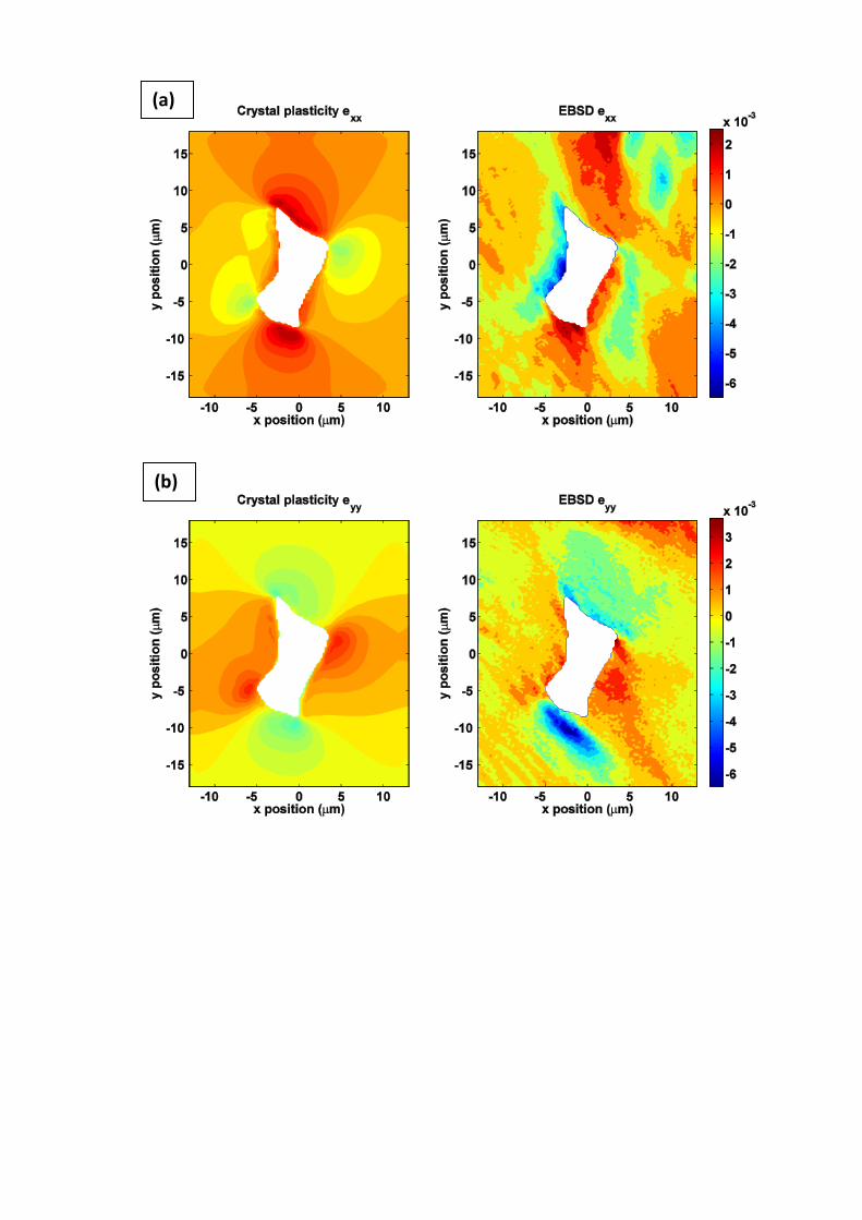
Figure 3 (a-d) shows contour plots of residual elastic strain components (𝑒𝑥𝑥, 𝑒𝑦𝑦, 𝑒𝑧𝑧 and
𝑒𝑥𝑦 respectively) obtained from high-resolution EBSD measurements local to the particle, on
the material free surface together with the corresponding CPFE results for the 75 m depth
model in which both particle and matrix are assumed to have the same depth, as shown in
Figure 2(a). Note that EBSD strain measurements are not available in the carbide particle.
Hence, strains within the carbide obtained from CPFE have not been shown in the field plots.
Dilatational strains resulting from temperature change are not captured by EBSD, so that in
order to make direct comparisons of the calculated CPFE results, the purely dilatational
strains and plastic strains have been subtracted from the total strains in order to generate the
distortional elastic strains.
As can be seen from the figures there are some aspects of the strains which are in good
agreement but others for which this is not the case. For example, the longitudinal strain
component ezz is found to be wrongly predicted in sign particularly very close to the particle.
In contrast, shear strain components predicted by CPFE are in good comparison with EBSD
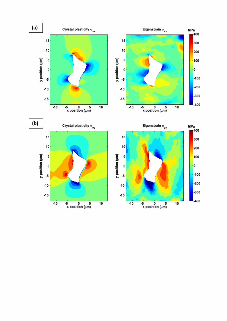
measurement. Figure 4(a-d) shows the contour plots of residual stress components (𝜎𝑥𝑥, 𝜎𝑦𝑦,
𝜎𝑧𝑧 and 𝜎𝑥𝑦) calculated using the CPFE and eigenstrain models at the subsurface ( z=-37.5
µm). While in-plane stress components obtained from the inverse method of eigenstrain show
similarities in comparison with those determined from the CPFE model, there are significant
differences for the longitudinal stress component. In order to illustrate the variation of the
residual stress component 𝜎𝑧𝑧 obtained from both methods, a line plot along y=0 is extracted
from the contour plot and shown in Figure 5. It is apparent that comparison shows very poor
agreement. A potential explanation for these differences is that the assumption made about
the carbide particle depth is wrong, and in order to investigate this, a second model is
analysed in which the particle depth is now taken to be considerably smaller than previously
assumed. In the second model, the carbide depth is now taken to be 5 µm within a 25 µm
13
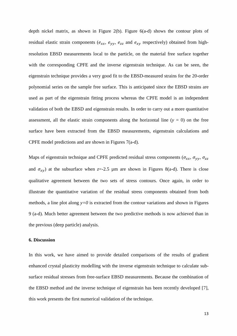
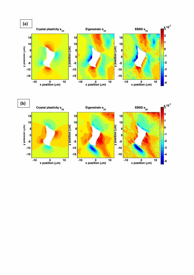
depth nickel matrix, as shown in Figure 2(b). Figure 6(a-d) shows the contour plots of
residual elastic strain components (𝑒𝑥𝑥, 𝑒𝑦𝑦, 𝑒𝑧𝑧 and 𝑒𝑥𝑦 respectively) obtained from high-
resolution EBSD measurements local to the particle, on the material free surface together
with the corresponding CPFE and the inverse eigenstrain technique. As can be seen, the
eigenstrain technique provides a very good fit to the EBSD-measured strains for the 20-order
polynomial series on the sample free surface. This is anticipated since the EBSD strains are
used as part of the eigenstrain fitting process whereas the CPFE model is an independent
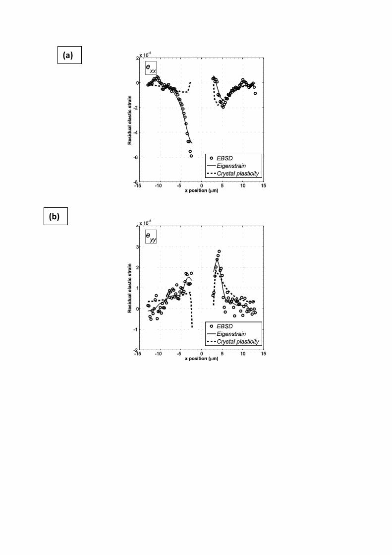
validation of both the EBSD and eigenstrain results. In order to carry out a more quantitative
assessment, all the elastic strain components along the horizontal line (y = 0) on the free
surface have been extracted from the EBSD measurements, eigenstrain calculations and
CPFE model predictions and are shown in Figures 7(a-d).
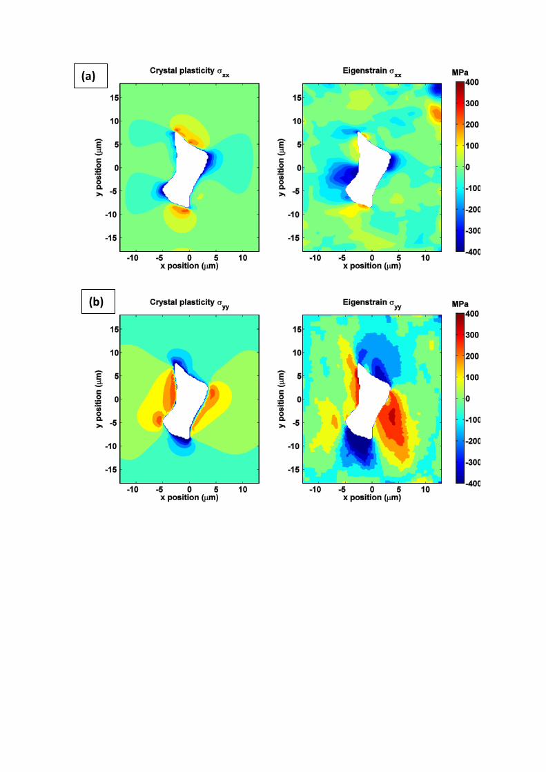
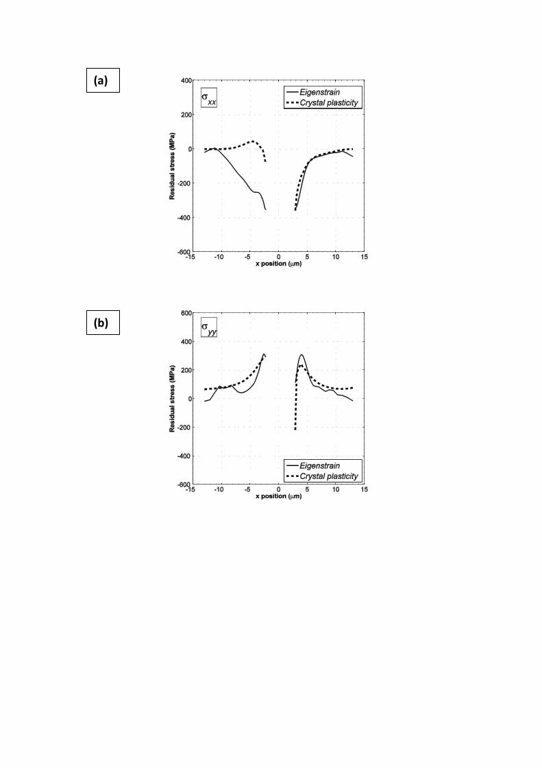
Maps of eigenstrain technique and CPFE predicted residual stress components (𝜎𝑥𝑥, 𝜎𝑦𝑦, 𝜎𝑧𝑧
and 𝜎𝑥𝑦) at the subsurface when z=-2.5 µm are shown in Figures 8(a-d). There is close
qualitative agreement between the two sets of stress contours. Once again, in order to
illustrate the quantitative variation of the residual stress components obtained from both
methods, a line plot along y=0 is extracted from the contour variations and shown in Figures
9 (a-d). Much better agreement between the two predictive methods is now achieved than in
the previous (deep particle) analysis.
6. Discussion
In this work, we have aimed to provide detailed comparisons of the results of gradient
enhanced crystal plasticity modelling with the inverse eigenstrain technique to calculate sub-
surface residual stresses from free-surface EBSD measurements. Because the combination of
the EBSD method and the inverse technique of eigenstrain has been recently developed [7],
this work presents the first numerical validation of the technique.
14
EBSD techniques (generally) give information only on free surfaces which can be quite
different to stress states which can exist sub-surface. Experimental observations in nickel
alloys show that fatigue crack nucleation is often associated with second phase particles
embedded within the primary phase matrix. In addition, geometrically necessary dislocations
can affect crack nucleation and growth [24], the initiation of recrystallization and the
nucleation of twinning. Hence, predictive lifing techniques require correctly determining
stress state and magnitude local to second phase particles at the appropriate length scale.
Thus, we have aimed to test the ability of the eigenstrain technique to provide this
information at a particular microstructural heterogeneity, and compared results with gradient-
enhanced crystal plasticity.
The approach is currently limited to problems containing only prismatic micro-structural
features. Consequently, some of the observed differences in the measured and predicted
results are due to the modelling assumptions made. For instance, while free-surface
modelling results have been compared properly with free-surface EBSD measurements, in the
model, the particle is assumed prismatic sub-surface; this is unlikely to be strictly the case in
reality. In addition, in the experimental Ni alloy material, while it is known that the carbide
particles are well-dispersed such that inter-particle effects are likely to be small, they cannot
be eliminated and the possibility always remains that additional local particles exist and
interact.
Comparisons of the sub-surface residual stresses from the CPFE model with the inverse
eigenstrain technique are promising, though there are some disagreements. Some of these
differences are attributed to the assumption made for the eigenstrain technique for which the
experimental data, on which the technique is based, is only available on the free surface (one
plane), and the variation of the eigenstrain components in the direction normal to the
measured surface therefore has to be assumed. In this work, the eigenstrains are assumed to
15
be invariant with particle depth. In order to investigate the validity of this assumption, the
variation of effective plastic strain from the CPFE model in Figure 2 (b) along the z-direction
from the free surface at the position y=0, x=3.4 µm (that is, very close to the nickel - carbide
boundary) is shown in Figure 10. As can be seen from the figure, crystal plasticity finite
element results produce a non-uniform plastic strain in the longitudinal direction, and this
therefore brings in to question the validity of the assumption being made for the eigenstrain
analysis. In addition, the assumptions being made in the crystal analysis may also be
reasonably questioned.
7. Conclusions
A 3D gradient-enhanced crystal plasticity finite element model has been developed for a
single-crystal nickel alloy sample containing a carbide particle subjected to cooling.
Comparisons of HR-EBSD-measured, CPFE and eigenstrain model-calculated elastic strains
at the sample free-surface show good quantitative agreement.
The elastic strains local to the embedded particle but now sub-surface are also predicted from
CPFE and eigenstrain modelling (in which the latter technique utilizes knowledge of the free
surface strains). The quality of the agreement is found to depend on the depth assumed for the
embedded particle, with better quantitative agreement being obtained for a shallow (as
opposed to prismatic, full-length) particle.
As expected, the key simplifying assumption made in the eigenstrain model that the 2D
inherent strain distribution remains uniform through the sample depth is found to lead to
differences in the CPFE and eigenstrain sub-surface elastic strain (and hence stress)
predictions. However, the results indicate that very good qualitative estimates of sub-surface
stresses are achievable using the eigenstrain technique with knowledge of EBSD free-surface
measurements.
16
8. References
1 . Hochhalter J.D., Littlewood D.J., Christ R.J., Veilleux M.G., Bozek J.E., Ingraffea, A.R.
and Maniatty A.M. (2010). A geometric approach to modeling microstructurally small fatigue
crack formation: II. Physically based modeling of microstructure-dependent slip localization
and actuation of the crack nucleation mechanism in AA 7075-T651. Modelling and
Simulation in Materials Science and Engineering., vol.18, 045004,
2. Dunne F.P.E., Wilkinson A.J and Allen R. (2007). Experimental and computational studies
of low cycle fatigue crack nucleation in a polycrystal. International Journal of Plasticity, vol.
23(2), pp.273-295.
3. Dunne F.P.E. (2014). Fatigue Crack Nucleation: Mechanistic modelling across the length
scales. Current Opinion in Solid State and Materials Science..
4. Wilkinson A.J., Clarke E.E., Britton T.B., Littlewood P. and Karamched P.S. (2010).High-
resolution electron backscatter diffraction: an emerging tool for studying local deformation.
The Journal of Strain Analysis for Engineering Design, vol. 45, pp. 365-375.
5. Dingley D.J., Wilkinson A.J., Meaden G. and Karamched P.S. (2010). Elastic strain tensor
measurement using electron backscatter diffraction in the SEM. Journal of Electron
Microscopy, vol. 59 (SUPPL. 1), pp. S155-S163.
6. Shade P., Groeber M., Schuren J. and Uchic M. (2013). Experimental measurement of
surface strains and local lattice rotations combined with 3D microstructure reconstruction
from deformed polycrystalline ensembles at the micro-scale. Integrating Materials and
Manufacturing Innovation, vol. 2 (5), pp. 1-14.
7. Kartal M.E., Dunne F.P.E. and Wilkinson A.J. (2012). Determination of the complete
micro-scale residual stress tensor at a sub-surface carbide particle in a single crystal
superalloy from free surface EBSD. Acta Materialia, vol. 60 (13-14), pp. 5300-5310.
8. Karamched P.S. and Wilkinson A.J. (2011). High resolution electron back-scatter
diffraction analysis of thermally and mechanically induced strains near carbide inclusions in a
superalloy. Acta Materialia, vol. 59 (1), pp. 263-272.
9. Wilkinson A.J., Meaden G. and Dingley, D.J. (2006). High resolution mapping of strains
and rotations using electron backscatter diffraction. Materials Science and Technology, vol.
22 (11), pp. 1271-1278.
10. Wilkinson A.J., Meaden G. and Dingley, D.J. (2006). High-resolution elastic strain
measurement from electron backscatter diffraction patterns: New levels of sensitivity.
Ultramicroscopy, vol. 106 (4-5), pp. 307-313.
11. Dunne F.P.E., Rugg D. and Walker A. (2007). Lengthscale-dependent, elastically
anisotropic, physically-based HCP crystal plasticity: Application to cold-dwell fatigue in Ti
alloys. International Journal of Plasticity, vol. 23 (6), pp.1061–1083.
17
12. Dunne F.P.E., Kiwanuka R. and Wilkinson A.J., (2012). Crystal plasticity analysis of
micro-deformation, lattice rotation and GND density. Proceedings of Royal Society A. , vol.
468, pp. 2509-2531.
13. Nye J.F. (1953). Some geometrical relations in dislocated crystals. Acta Metallurgica,
vol. 1 (2), pp. 153–162.
14. Busso E., Meissonier F.T. and O’Dowd N.P. (2000). Gradient-dependent deformation of
two-phase single crystals. Journal of the Mechanics and Physics of Solids, vol. 48 (11), pp.
2333–2361.
15. Acharya A. and Bassani J.L. (2000). Lattice incompatibility and a gradient theory of
crystal plasticity. Journal of the Mechanics and Physics of Solids, vol. 48 (8), pp. 1565-1595.
16. Arsenlis A. and Parks D.M. (1999). Crystallographic aspects of geometrically-necessary
and statistically-stored dislocation density. Acta Materialia, vol. 47 (5), pp. 1597-1611.
17. Kartal M.E., Liljedahl C.D.M., Gungor S., Edwards L. and Fitzpatrick M.E. (2008).
Determination of the profile of the complete residual stress tensor in a VPPA weld using the
multi-axial contour method. Acta Materialia, vol. 56 (16), pp. 4417-4428.
18. Song X. and Korsunsky A.M. (2011). Fully two-dimensional discrete inverse eigenstrain
analysis of residual stresses in a railway rail head. Journal of Applied Mechanics, vol. 78 (3),
031019.
19. Jun T.-S., Venter A.M. and Korsunsky A.M. (2011). Inverse eigenstrain analysis of the
effect of non-uniform sample shape on the residual stress due to shot peening, Experimental
Mechanics, vol. 51 (2), pp. 165-174.
20. Jun T.-S. and Korsunsky A.M. (2010). Evaluation of residual stresses and strains using
the eigenstrain reconstruction method. International Journal of Solids and Structures, vol. 47
(13), pp. 1678-1686.
21. Schajer G.S. (1981). Application of finite element calculations to residual stress
measurements. Journal of Engineering Materials and Technology, vol.103, pp.157-163.
22. Cheng W. and Finnie I. (1985). A method for measurement of axisymmetric residual
stresses in circumferentially welded thin-walled cylinders. Journal of Engineering Materials
and Technology, vol.107, pp.181-185.
23. Korsunsky A.M., Regino G.M., Latham D.P., Li H.Y. and Walsh M. J. (2007). Residual
stresses in rolled and machined nickel alloy plates: synchrotron x-ray diffraction
measurement and three-dimensional eigenstrain analysis. The Journal of Strain Analysis for
Engineering Design, vol. 42, pp. 1–12.
24. Sweeney. C.A., Vorster W., Leen S.B., Sakurada E., Dunne F.P.E. (2013). The role of
elastic anisotropy, length scale and crystallographic slip in fatigue crack nucleation. Journal
of Mechanics and Physics of Solids, vol. 61, pp. 1224–1240.
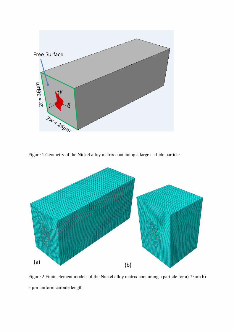
Figure 1 Geometry of the Nickel alloy matrix containing a large carbide particle
Figure 2 Finite element models of the Nickel alloy matrix containing a particle for a) 75μm b)
5 μm uniform carbide length.
(a)
(b)
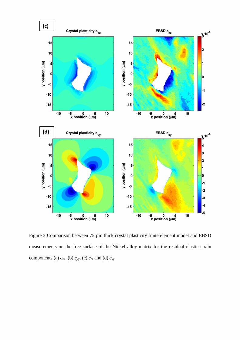
Figure 3 Comparison between 75 µm thick crystal plasticity finite element model and EBSD
measurements on the free surface of the Nickel alloy matrix for the residual elastic strain
components (a) exx, (b) eyy, (c) ezz and (d) exy
(c)
(d)
(a)
(b)
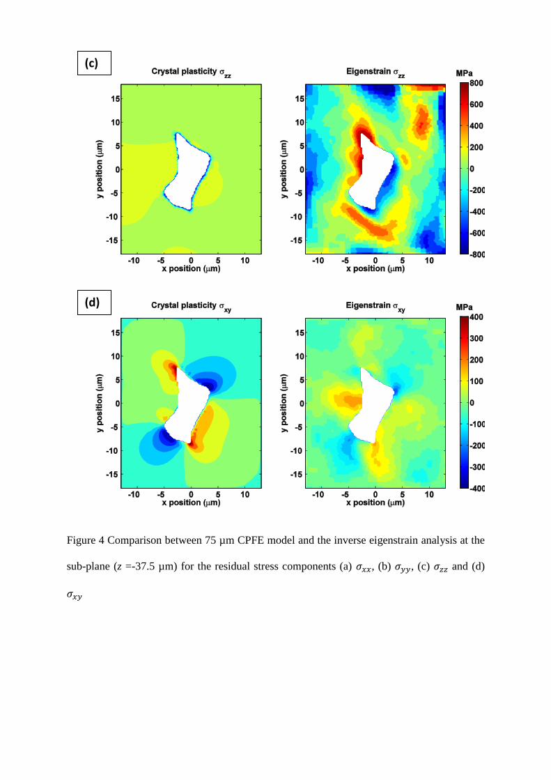
Figure 4 Comparison between 75 µm CPFE model and the inverse eigenstrain analysis at the
sub-plane (z =-37.5 µm) for the residual stress components (a) , (b) , (c) and (d)
(c)
(d)
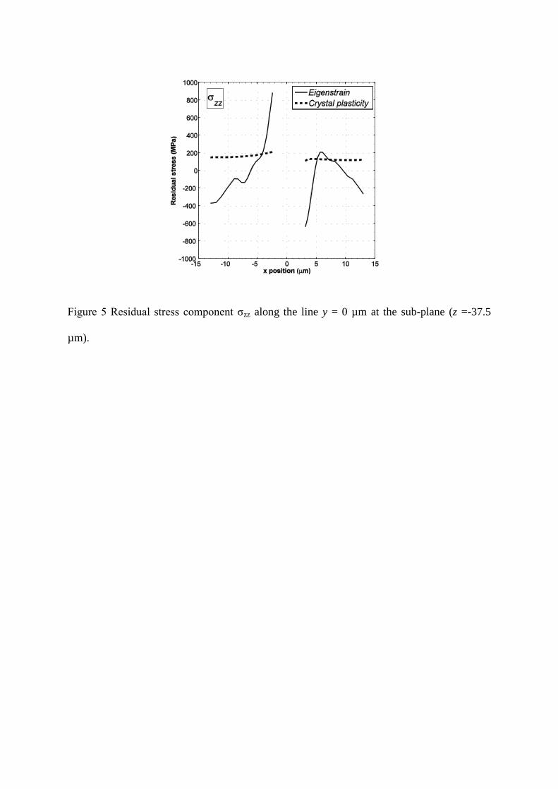
Figure 5 Residual stress component σzz along the line y = 0 µm at the sub-plane (z =-37.5
µm).
(b)
(a)
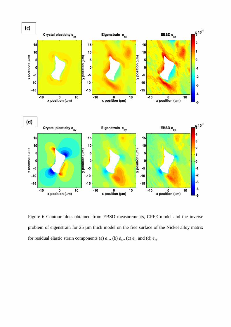
Figure 6 Contour plots obtained from EBSD measurements, CPFE model and the inverse
problem of eigenstrain for 25 µm thick model on the free surface of the Nickel alloy matrix
for residual elastic strain components (a) exx, (b) eyy, (c) ezz and (d) exy
(d)
(c)
(b)
(a)
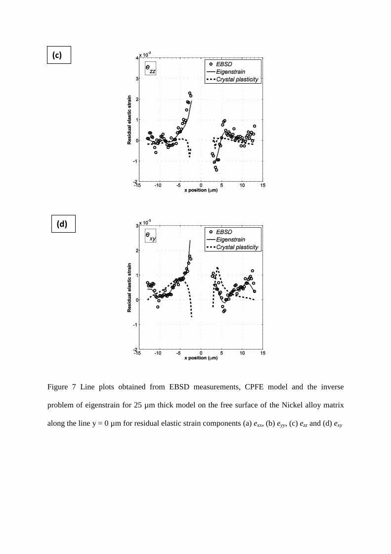
Figure 7 Line plots obtained from EBSD measurements, CPFE model and the inverse
problem of eigenstrain for 25 µm thick model on the free surface of the Nickel alloy matrix
along the line y = 0 µm for residual elastic strain components (a) exx, (b) eyy, (c) ezz and (d) exy
(d)
(c)
(b)
(a)
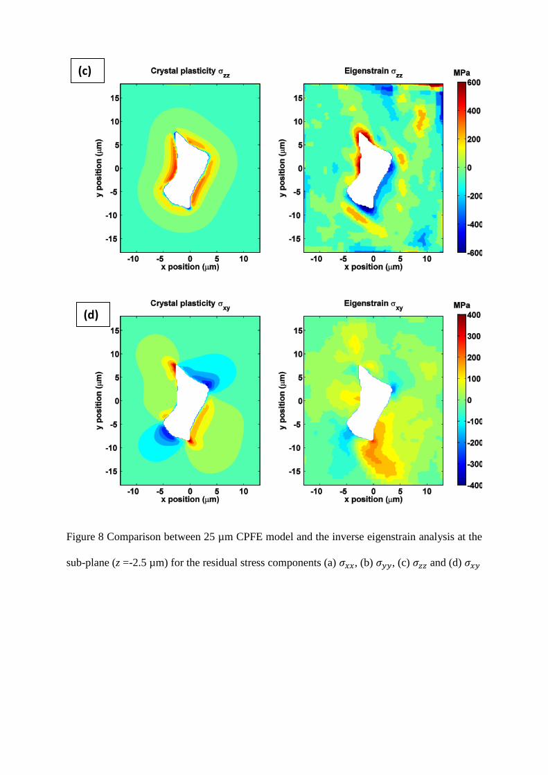
Figure 8 Comparison between 25 µm CPFE model and the inverse eigenstrain analysis at the
sub-plane (z =-2.5 µm) for the residual stress components (a) , (b) , (c) and (d)
(d)
(c)
(b)
(a)
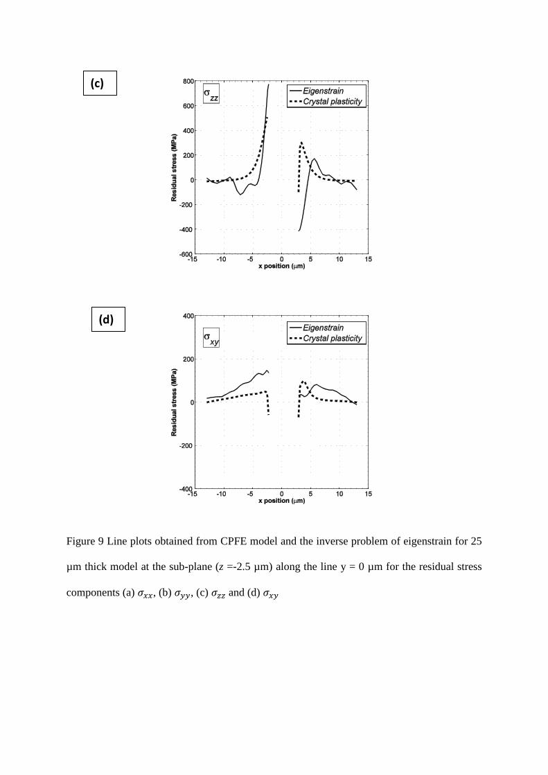
Figure 9 Line plots obtained from CPFE model and the inverse problem of eigenstrain for 25
µm thick model at the sub-plane (z =-2.5 µm) along the line y = 0 µm for the residual stress
components (a) , (b) , (c) and (d)
(d)
(c)
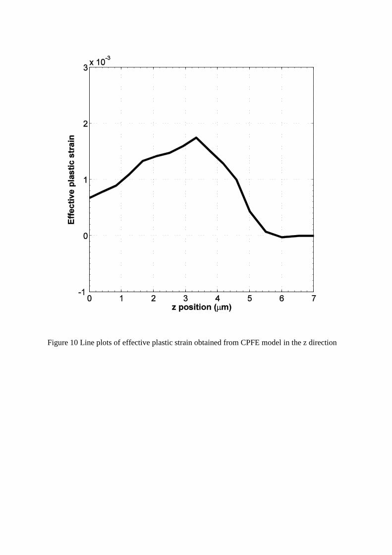
Figure 10 Line plots of effective plastic strain obtained from CPFE model in the z direction