Embed Size (px)
Citation preview
Developing a Tire Mill for 3D-Printing
With Recycled Materials
Max Troedsson
Division of Machine Design ᐧ Department of Design Sciences Faculty of Engineering LTH ᐧ Lund University ᐧ 2016
Developing a Tire Mill for 3D-Printing With Recycled Materials
Max Troedsson
Division of Machine Design ᐧ Department of Design Sciences
Faculty of Engineering LTH ᐧ Lund Univserity ᐧ 2016
Division of Design, Depart of Design Sciences Faculty of Engineering LTH, Lund University P.O. Box 118 SE-221 00 Lund Sweden
i
Preface and Acknowledgements As a project based on one meant for the favelas of Brazil, by Charlotta Engstrand, and commissioned by the Division of Machine Design, this Master thesis in Mechanical Engineering, Product Development has been executed at Lund University, Faculty of Engineering. This project would not have happened without the help and guidance of people whose input I value highly. I would like to start off by thanking my supervisor Prof. Olaf Diegel at the Division of Machine Design, for offering the opportunity to work with a project such as this, as well as being a running source of insight, and input, and for all the time he has made available for meetings with me despite having a very busy schedule. I would also like to thank my examiner, Prof. Giorgos Nikoleris for the feedback he has provided. Next, thanks to Sten Berge for workshop help, and to the staff at the workshops of LTH’s A-building and IKDC for using their tools and materials that were critical to the completion of this project. I would like to thank Oscar Holm as well as Jakob Wilson for bicycle related questions, and Jesper at Vulko here in Lund for readily providing me with a variety used tires. Finally, I would like to thank my parents for their support and encouragement during this project. My time in Lund has been a fantastic series of different challenges and amazing experiences. I look forward to facing both the challenges and opportunities that await me. Lund, June 2016 Max Troedsson
ii
Abstract This project builds on the project Charlotta Engstrand did under the fall semester of 2016. The 3D printer she developed used pulverised thermoplastics, as well as pulverised tires. Her project was directed specifically towards being applicable in the favelas of Brazil, to introduce 3D printing to those with economic means more realistic to their situation, primarily through using resources otherwise considered as waste. Both tires and thermoplastics are very easy to acquire, and are thusly to be considered an excellent resource, if viable. As a thermoplastic, PET bottles were used. As tires, both summer and friction tires were used. What this project aimed at solving was to develop and construct a proof of concept of a solution meant to pulverise a tire in an effective and easily accomplished way. This solution was meant to be constructed on-site with the resources available, as well as possible. The main focus has been to pulverise vulcanised rubber from tires, with a complimentary ground work done to produce an analogue solution for thermoplastics. Engstrand’s project mentioned the pulverisation of rubber to be a time-consuming process, which could be made more efficient to make her 3D printer more attractive to the areas meant for implementation. This choice of processing rubber was made due to the fact that tires are more difficult to recycle, and quickly proved to be the easiest of the two main materials to process, but also to make the project feasible within the available timeframe. The geographic focus of Engstrand’s project was widened for this report, to encompass both favelas and areas with similar conditions. Since tires contain a variety of materials, steel and textile among others, it was never the goal to process all the rubber in the tire. The part of the tire to be processed was the tread, since there often is a significant amount of rubber still easily available even though the tread itself may be worn out. Besides this, the sidewalls offered a pristine area for fastening the tire, to regulate its rotation to ensure an even processing of the tire circumference. First, different methods for pulverising the two materials were researched. This resulted in a method which worked best for each material: for rubber, a belt sander provided the best results; for plastics, an electric rasp did the same. Different solutions for how the tire was processed in the cheapest and best way were further researched. Thereafter, these ideas were tested, and new iterations were produced to solve the shortcomings of the previous versions. Late in the development process, the final version was modified to facilitate the collection of the produced rubber granulate. This collected granulate to a space suitable for a plate, a folded down plastic bag, or another surface suitable for collecting the pulverised rubber. Keywords: 3D-printing, recycled rubber, recycled plastic, low-cost, sustainability
iii
Sammanfattning Detta projekt gjordes för att komplettera det projekt Charlotta Engstrand gjorde under höstterminen 2015. Den 3D-printer som hon utvecklade använder sig av pulveriserad termoplast och pulveriserade bildäck. Hennes projekt riktade sig specifikt till att vara applicerbart i brasilianska favelor, för att introducera 3D-printing för dem på ekonomiska villkor som var mer realistiska för deras situation, huvudsakligen genom att använda resurser som annars räknas som avfall. Både bildäck och termoplast finns att tillgå enkelt och billigt, och är således en utmärkt resurs om detta är gångbart. Som termoplast användes PET-flaskor, och som däck användes både sommardäck och friktionsdäck. Det detta projektet ämnade att lösa var att utveckla och konstruera ett proof-of-concept på en lösning för att pulverisera däcket på ett effektivt och lätthanterligt sätt. Denna lösning är tänkt att kunna konstrueras på plats med de resurser som finns tillhands i så stor utsträckning som möjligt. Det huvudsakliga fokuset har varit på att pulverisera vulkaniserat gummi från bildäck, med tillhörande grundarbete för att kunna göra en motsvarande lösning för plast. I Engstrand’s projekt nämns detta som något som var tidskrävande och behöver kunna göras smidigare för att denna 3D-skrivare ska vara attraktiv för dess implementationsområde. Detta val gjordes eftersom gummit är svårast att återvinna och snabbt visade sig vara enklast att bearbeta av de två, men även för att projektet skulle kunna genomföras inom den givna tidsramen. Det geografiska fokus som Engstrands projekt hade har vidgats för denna rapport, och lösningen ämnar till att vara genomförbar i både favelor och i andra områden med liknande förutsättningar. Eftersom ett bildäck innehåller ett antal olika material, bl a stål och textil, var målet aldrig att bearbeta allt gummi som fanns i däcket. Den delen av däcket som bearbetades var mönstret, eftersom där ofta finns användbart och lättillgängligt gummi kvar även efter att mönstret eventuellt slitits ned. Dessutom erbjöd sidorna bäst fästyta för att reglera dess rotation för att sörja för en jämn bearbetningsyta runtom däcket. Först utforskades olika metoder för att pulverisera de båda materialen. Detta resulterade i en metod som fungerade bäst för vardera material: för gummiberarbetning gav slipmaskin med sandpappersband bäst resultat, och för plast gav elektriskt rivjärn bäst resultat. Olika lösningar på hur däcket skulle kunna bearbetas enkelt och billigt undersöktes. Därefter konstruerades och testades idéerna, och nya iterationer gjordes för att lösa tidigare versioners tillkortakommanden. Den slutgiltiga versionen modifierades sent i processen för att förenkla insamlingen av det producerade gummipulvret. Detta samlade det producerade gummipulvret inom en begränsad yta, inom vilken en tallrik, utvikt plastpåse, eller annan yta kunde läggas för att samla upp det av processen resulterande pulveriserade gummit.
iv
Table of Contents Abstract ...................................................................................................................................................ii
Sammanfattning .................................................................................................................................... iii
Table of Contents ................................................................................... Error! Bookmark not defined.
1 Introduction ......................................................................................................................................... 1
1.1 Background ................................................................................................................................. 1
1.2 Aims and Purposes .................................................................................................................... 1
1.3 Problem Formulation ................................................................................................................. 1
1.4 Objectives .................................................................................................................................... 2
1.5 Assumptions, Limitations, and Delimitations ......................................................................... 2
2 Method ................................................................................................................................................ 3
2.1 Product Design and Development Process ........................................................................... 3
2.1.1 Test Product Concept ........................................................................................................ 3
2.1.2 Initial Brainstorming ............................................................................................................ 4
2.2 Iteration 1: The Crate ................................................................................................................. 4
2.3 Iteration 2: The Crate with Brake Lever .................................................................................. 5
2.4 Iteration 3: The Wheeled Crate ................................................................................................ 6
2.5 Iteration 4: Crate with Bike Parts ............................................................................................. 7
2.6 Iteration 5: Peripheral Direct Drive .......................................................................................... 8
2.7 Iteration 6: Axial Direct Drive .................................................................................................... 9
2.8 For Plastic: The Electric Grater .............................................................................................. 11
3 Materials ........................................................................................................................................... 13
3.1 Pulverising tires ........................................................................................................................ 13
3.2 Pulverising plastics .................................................................................................................. 15
3.2.1 .............................................................................................................................................. 16
3.1 Acquiring materials .................................................................................................................. 16
4 Mill chassis design and setup ........................................................................................................ 17
4.1 Functions ................................................................................................................................... 17
4.2 Assembly ................................................................................................................................... 17
4.3 Design ........................................................................................................................................ 17
5 Materials Used ................................................................................................................................. 18
6 Final Results..................................................................................................................................... 19
6.1 Results from Method Testing ................................................................................................. 19
6.2 Results from Mill Iterations ..................................................................................................... 20
7 Discussion and Future Work ......................................................................................................... 21
v
7.1 Scope ......................................................................................................................................... 21
7.2 Method ....................................................................................................................................... 21
7.3 Choice of Materials .................................................................................................................. 21
7.4 Testing, Initial and Later .......................................................................................................... 21
7.5 Final Results ............................................................................................................................. 22
7.6 Time Schedule .......................................................................................................................... 22
7.7 Future Work .............................................................................................................................. 22
7.8 Self Evaluation .......................................................................................................................... 22
References .......................................................................................................................................... 24
............................................................................................................................................................... 24
Appendixes: See attached
Appendix A: Time Schedule
A1: Intended Time Schedule
A2: Actual Time Schedule
Appendix B: Drawings and Stencils
1
1 Introduction In this section, the project and its purpose is presented.
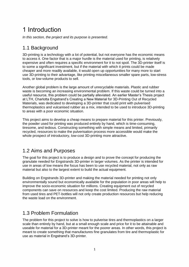
1.1 Background 3D-printing is a technology with a lot of potential, but not everyone has the economic means to access it. One factor that is a major hurdle is the material used for printing, is relatively expensive and often requires a specific environment for it to not spoil. The 3D-printer itself is to some a significant investment, but if the material with which it prints could be made cheaper and more readily available, it would open up opportunities for many more to start use 3D-printing to their advantage, like printing miscellaneous smaller spare parts, low-stress tools, or low-volume products to sell. Another global problem is the large amount of unrecyclable materials. Plastic and rubber waste is becoming an increasing environmental problem. If this waste could be turned into a useful resource, this problem could be partially alleviated. An earlier Master’s Thesis project at LTH, Charlotta Engstrand’s Creating a New Material for 3D-Printing Out of Recycled Materials, was dedicated to developing a 3D-printer that could print with pulverised thermoplastics and vulcanised rubber as a mix, intended to be used to introduce 3D-printing to areas with a poor economic situation. This project aims to develop a cheap means to prepare material for this printer. Previously, the powder used for printing was produced entirely by hand, which is time-consuming, tiresome, and tedious. Constructing something with simple means and limited, primarily recycled, resources to make the pulverisation process more accessible would make the whole prospect of introductory, low-cost 3D-printing more attractive.
1.2 Aims and Purposes The goal for this project is to produce a design and to prove the concept for producing the granulate needed for Engstrands 3D-printer in larger volumes. As the printer is intended for use in areas of low means the focus has been to use recycled material, not only as raw material but also to the largest extent to build the actual equipment. Building on Engstrands 3D-printer and making the material needed for printing not only environmentally sound but economically available for the population in poor areas will help to improve the socio-economic situation for millions. Creating equipment out of recycled components can save on resources and keep the cost limited. Producing the raw material from used tires and PET-bottles will not only create production resources but help reducing the waste load on the environment.
1.3 Problem Formulation The problem for this project to solve is how to pulverise tires and thermoplastics on a larger scale than entirely by hand, but at a small enough scale and price for it to be attainable and useable for material for a 3D-printer meant for the poorer areas. In other words, this project is meant to create something that manufactures fine granulates from tire and thermoplastic for use as material in Engstrand’s 3D-printer.
2
1.4 Objectives Examine methods suitable for manufacturing powder from both vulcanized rubber
from old tires and thermoplastic items.
Manufacture powders from both vulcanized rubber from old tires and thermoplastic
items.
Create a prototype for a proof of concept to produce these powders that is cheap to
produce and is possible to reproduce at low cost in areas with relatively scarce resources.
Create means for production and entrepreneurial activities in areas where resources are scarce without creating an increased environmental load.
1.5 Assumptions, Limitations, and Delimitations For this project, a number of assumptions, limitations, and delimitations had to be made, and are described below.
The rubber powder created will not be of an as high quality as might be possible, partly because of residual wood dust in the belt sander, but also from dirt on the tires, but also from miscellaneous dirt already on the tires. However, the scope of this project does not include optimisation of the powder quality. On top of this, the application area for this project does not necessarily lend itself at all to such care being taken.
In this project, there will only be a cursory attempt at pulverising plastic. The
reasoning behind this is that the tires are more troublesome to pulverise and therefore require a more thorough investigation into techniques to make this easier. There are multiple ways of varying ease with which to pulverise plastic with relatively readily available equipment, as will be described later on.
Testing the produced powder in the 3D-printer that Engstrand developed will not be
made in this project. This is because the printer in question seemed sufficiently difficult to assemble, clear out, and prepare for use that is was concluded sufficient that Engstrand’s work would suffice as basis for it working, so long as the powder produced was of the same or finer quality than that which was produced in her project. Hence, only production of pulverised material will be examined herein; all further testing to verify the viability of the material as material for 3D-printing, with regards to shrinkage, sedimenting in the printer, or anything of the sort will have to be covered in another project.
This project aims to develop a design and a proof of concept for pulverising tires.
Furthermore, a cursory study is made to do the same for thermoplastic 50 cl bottles. Many variations and improvements have to be made for this to be better suited for direct application in the poorer areas.
3
2 Method For this project, Ulrich & Eppinger’s Product Design and Development Process [1] was used as the primary source for a method process. However, the process described by Ulrich and Eppinger [1] was not used in its entirety, as this project only aims to cover a subprocess, namely proving the concept. Besides this, the specific methodology used is described below, both in its steps and in its deviations from the original sequence.
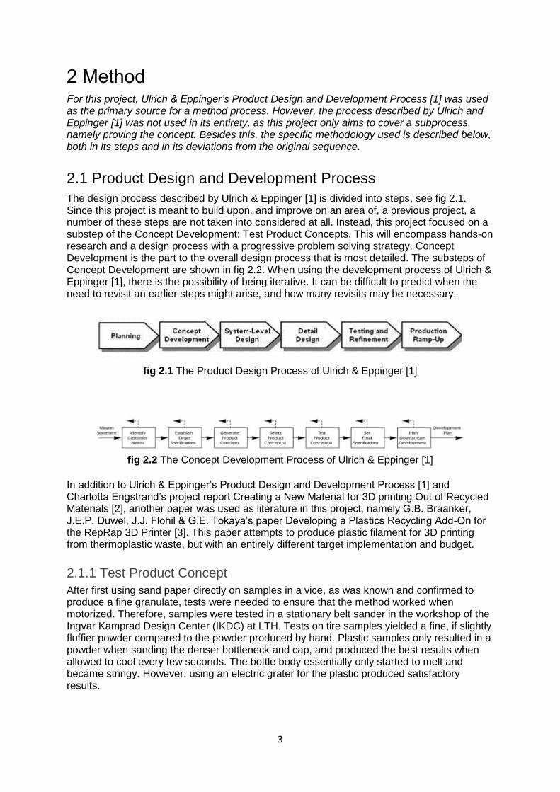
2.1 Product Design and Development Process The design process described by Ulrich & Eppinger [1] is divided into steps, see fig 2.1. Since this project is meant to build upon, and improve on an area of, a previous project, a number of these steps are not taken into considered at all. Instead, this project focused on a substep of the Concept Development: Test Product Concepts. This will encompass hands-on research and a design process with a progressive problem solving strategy. Concept Development is the part to the overall design process that is most detailed. The substeps of Concept Development are shown in fig 2.2. When using the development process of Ulrich & Eppinger [1], there is the possibility of being iterative. It can be difficult to predict when the need to revisit an earlier steps might arise, and how many revisits may be necessary.
fig 2.1 The Product Design Process of Ulrich & Eppinger [1]
fig 2.2 The Concept Development Process of Ulrich & Eppinger [1]
In addition to Ulrich & Eppinger’s Product Design and Development Process [1] and Charlotta Engstrand’s project report Creating a New Material for 3D printing Out of Recycled Materials [2], another paper was used as literature in this project, namely G.B. Braanker, J.E.P. Duwel, J.J. Flohil & G.E. Tokaya’s paper Developing a Plastics Recycling Add-On for the RepRap 3D Printer [3]. This paper attempts to produce plastic filament for 3D printing from thermoplastic waste, but with an entirely different target implementation and budget.
2.1.1 Test Product Concept
After first using sand paper directly on samples in a vice, as was known and confirmed to produce a fine granulate, tests were needed to ensure that the method worked when motorized. Therefore, samples were tested in a stationary belt sander in the workshop of the Ingvar Kamprad Design Center (IKDC) at LTH. Tests on tire samples yielded a fine, if slightly fluffier powder compared to the powder produced by hand. Plastic samples only resulted in a powder when sanding the denser bottleneck and cap, and produced the best results when allowed to cool every few seconds. The bottle body essentially only started to melt and became stringy. However, using an electric grater for the plastic produced satisfactory results.
4
2.1.2 Initial Brainstorming
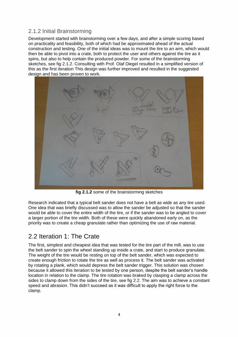
Development started with brainstorming over a few days, and after a simple scoring based on practicality and feasibility, both of which had be approximated ahead of the actual construction and testing. One of the initial ideas was to mount the tire to an arm, which would then be able to pivot into a crate, both to protect the user and others against the tire as it spins, but also to help contain the produced powder. For some of the brainstorming sketches, see fig 2.1.2. Consulting with Prof. Olaf Diegel resulted in a simplified version of this as the first iteration This design was further improved and resulted in the suggested design and has been proven to work.
fig 2.1.2 some of the brainstorming sketches
Research indicated that a typical belt sander does not have a belt as wide as any tire used. One idea that was briefly discussed was to allow the sander be adjusted so that the sander would be able to cover the entire width of the tire, or if the sander was to be angled to cover a larger portion of the tire width. Both of these were quickly abandoned early on, as the priority was to create a cheap granulate rather than optimizing the use of raw material.
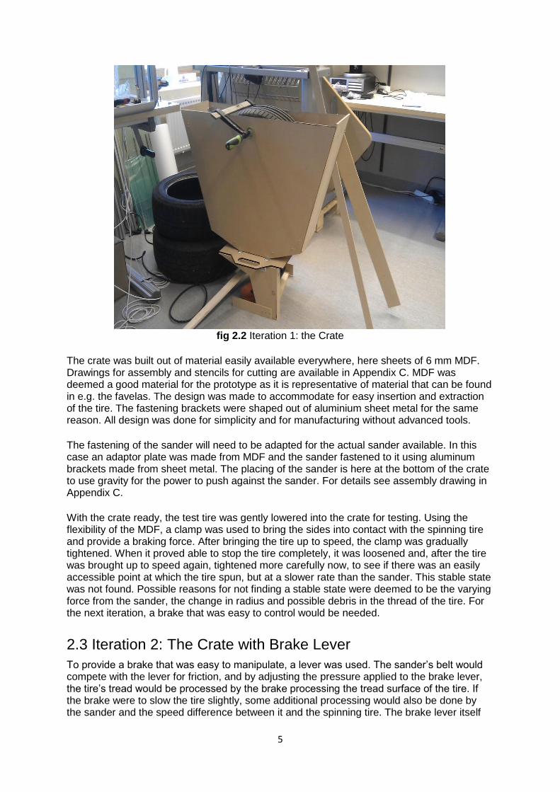
2.2 Iteration 1: The Crate The first, simplest and cheapest idea that was tested for the tire part of the mill, was to use the belt sander to spin the wheel standing up inside a crate, and start to produce granulate. The weight of the tire would be resting on top of the belt sander, which was expected to create enough friction to rotate the tire as well as process it. The belt sander was activated by rotating a plank, which would depress the belt sander trigger. This solution was chosen because it allowed this iteration to be tested by one person, despite the belt sander’s handle location in relation to the clamp. The tire rotation was braked by clasping a clamp across the sides to clamp down from the sides of the tire, see fig 2.2. The aim was to achieve a constant speed and abrasion. This didn’t succeed as it was difficult to apply the right force to the clamp.
5
fig 2.2 Iteration 1: the Crate
The crate was built out of material easily available everywhere, here sheets of 6 mm MDF. Drawings for assembly and stencils for cutting are available in Appendix C. MDF was deemed a good material for the prototype as it is representative of material that can be found in e.g. the favelas. The design was made to accommodate for easy insertion and extraction of the tire. The fastening brackets were shaped out of aluminium sheet metal for the same reason. All design was done for simplicity and for manufacturing without advanced tools. The fastening of the sander will need to be adapted for the actual sander available. In this case an adaptor plate was made from MDF and the sander fastened to it using aluminum brackets made from sheet metal. The placing of the sander is here at the bottom of the crate to use gravity for the power to push against the sander. For details see assembly drawing in Appendix C. With the crate ready, the test tire was gently lowered into the crate for testing. Using the flexibility of the MDF, a clamp was used to bring the sides into contact with the spinning tire and provide a braking force. After bringing the tire up to speed, the clamp was gradually tightened. When it proved able to stop the tire completely, it was loosened and, after the tire was brought up to speed again, tightened more carefully now, to see if there was an easily accessible point at which the tire spun, but at a slower rate than the sander. This stable state was not found. Possible reasons for not finding a stable state were deemed to be the varying force from the sander, the change in radius and possible debris in the thread of the tire. For the next iteration, a brake that was easy to control would be needed.
2.3 Iteration 2: The Crate with Brake Lever To provide a brake that was easy to manipulate, a lever was used. The sander’s belt would compete with the lever for friction, and by adjusting the pressure applied to the brake lever, the tire’s tread would be processed by the brake processing the tread surface of the tire. If the brake were to slow the tire slightly, some additional processing would also be done by the sander and the speed difference between it and the spinning tire. The brake lever itself
6
was an MDF-board with a smaller board covered with sandpaper. To simplify the construction as much as possible, the hinge for the brake lever was reduced to two nails through either side board into the short ends of a piece of plank screwed to the lever’s main MDF-board piece. After the tire had been lowered into the crate for testing, several tests were performed. After different attempts with varying pressure on the brake, the arm proved to work as a brake, but to be providing too much braking power. The tire’s rotation was stopped completely even when the brake was pushing down with only its own weight. The sander’s grip could have been increased with more pressure from the tire on the sander. However, this would only achieve the desired effect if the additional pressure on the tire was exerted by something allowed to spin freely and/or created very little friction between it and the tire, to keep it from acting as a brake in itself.
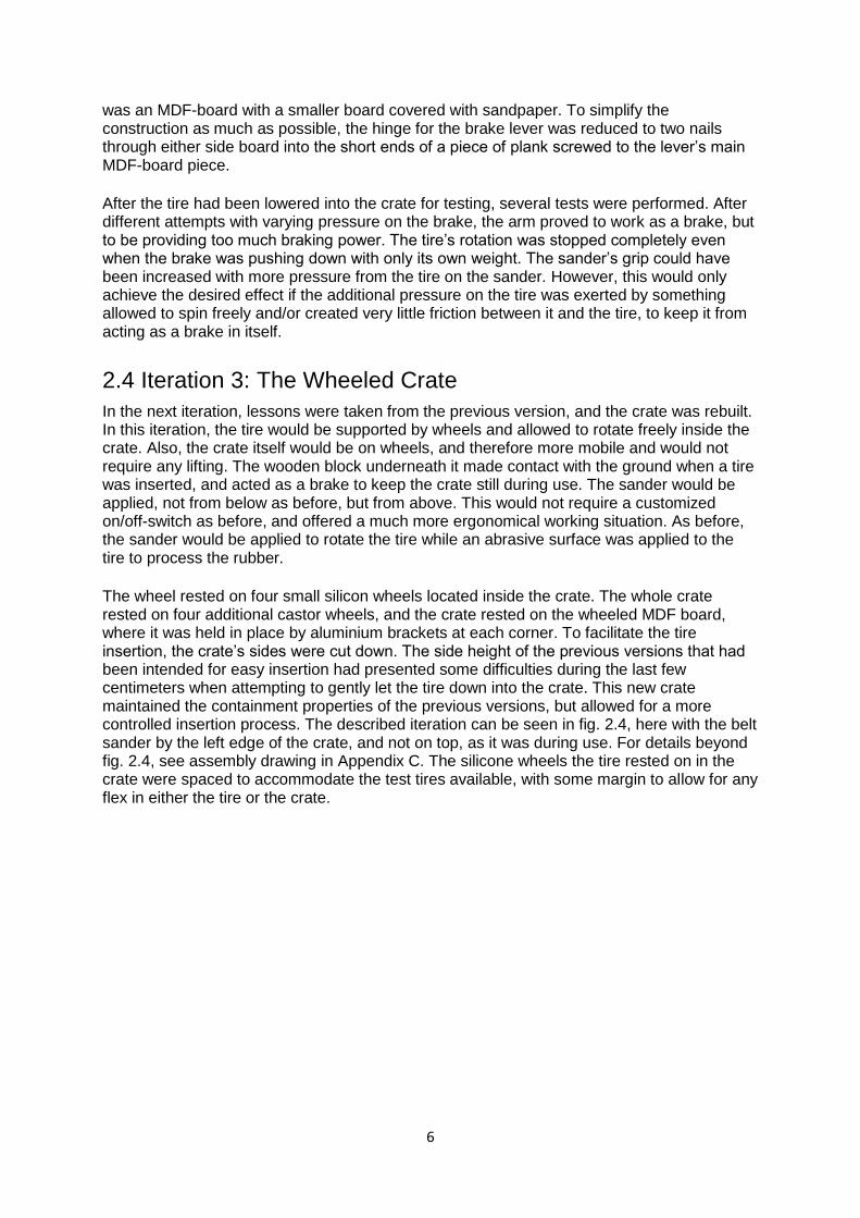
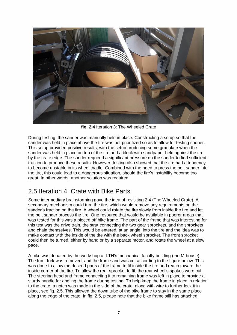
2.4 Iteration 3: The Wheeled Crate In the next iteration, lessons were taken from the previous version, and the crate was rebuilt. In this iteration, the tire would be supported by wheels and allowed to rotate freely inside the crate. Also, the crate itself would be on wheels, and therefore more mobile and would not require any lifting. The wooden block underneath it made contact with the ground when a tire was inserted, and acted as a brake to keep the crate still during use. The sander would be applied, not from below as before, but from above. This would not require a customized on/off-switch as before, and offered a much more ergonomical working situation. As before, the sander would be applied to rotate the tire while an abrasive surface was applied to the tire to process the rubber. The wheel rested on four small silicon wheels located inside the crate. The whole crate rested on four additional castor wheels, and the crate rested on the wheeled MDF board, where it was held in place by aluminium brackets at each corner. To facilitate the tire insertion, the crate’s sides were cut down. The side height of the previous versions that had been intended for easy insertion had presented some difficulties during the last few centimeters when attempting to gently let the tire down into the crate. This new crate maintained the containment properties of the previous versions, but allowed for a more controlled insertion process. The described iteration can be seen in fig. 2.4, here with the belt sander by the left edge of the crate, and not on top, as it was during use. For details beyond fig. 2.4, see assembly drawing in Appendix C. The silicone wheels the tire rested on in the crate were spaced to accommodate the test tires available, with some margin to allow for any flex in either the tire or the crate.
7
fig. 2.4 Iteration 3: The Wheeled Crate
During testing, the sander was manually held in place. Constructing a setup so that the sander was held in place above the tire was not prioritized so as to allow for testing sooner. This setup provided positive results, with the setup producing some granulate when the sander was held in place on top of the tire and a block with sandpaper held against the tire by the crate edge. The sander required a significant pressure on the sander to find sufficient traction to produce these results. However, testing also showed that the tire had a tendency to become unstable in its wheel cradle. Combined with the need to press the belt sander into the tire, this could lead to a dangerous situation, should the tire’s instability become too great. In other words, another solution was required.
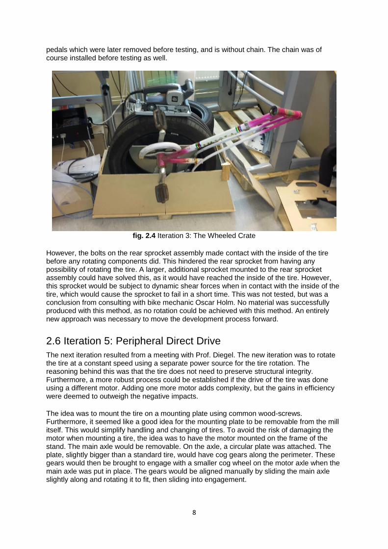
2.5 Iteration 4: Crate with Bike Parts Some intermediary brainstorming gave the idea of revisiting 2.4 (The Wheeled Crate). A secondary mechanism could turn the tire, which would remove any requirements on the sander’s traction on the tire. A wheel could rotate the tire slowly from inside the tire and let the belt sander process the tire. One resource that would be available in poorer areas that was tested for this was a pieced off bike frame. The part of the frame that was interesting for this test was the drive train, the strut connecting the two gear sprockets, and the sprockets and chain themselves. This would be entered, at an angle, into the tire and the idea was to make contact with the inside of the tire with the back wheel sprocket. The front sprocket could then be turned, either by hand or by a separate motor, and rotate the wheel at a slow pace. A bike was donated by the workshop at LTH’s mechanical faculty building (the M-house). The front fork was removed, and the frame and was cut according to the figure below. This was done to allow the desired parts of the frame to fit inside the tire and reach toward the inside corner of the tire. To allow the rear sprocket to fit, the rear wheel’s spokes were cut. The steering head and frame connecting it to remaining frame was left in place to provide a sturdy handle for angling the frame during testing. To help keep the frame in place in relation to the crate, a notch was made in the side of the crate, along with wire to further lock it in place, see fig. 2.5. This allowed the down tube of the bike frame to stay in the same place along the edge of the crate. In fig. 2.5, please note that the bike frame still has attached
8
pedals which were later removed before testing, and is without chain. The chain was of course installed before testing as well.
fig. 2.4 Iteration 3: The Wheeled Crate
However, the bolts on the rear sprocket assembly made contact with the inside of the tire before any rotating components did. This hindered the rear sprocket from having any possibility of rotating the tire. A larger, additional sprocket mounted to the rear sprocket assembly could have solved this, as it would have reached the inside of the tire. However, this sprocket would be subject to dynamic shear forces when in contact with the inside of the tire, which would cause the sprocket to fail in a short time. This was not tested, but was a conclusion from consulting with bike mechanic Oscar Holm. No material was successfully produced with this method, as no rotation could be achieved with this method. An entirely new approach was necessary to move the development process forward.
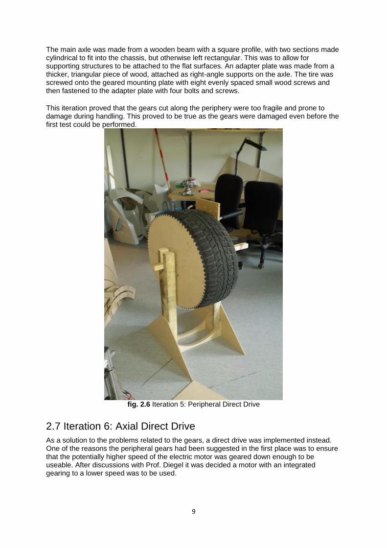
2.6 Iteration 5: Peripheral Direct Drive The next iteration resulted from a meeting with Prof. Diegel. The new iteration was to rotate the tire at a constant speed using a separate power source for the tire rotation. The reasoning behind this was that the tire does not need to preserve structural integrity. Furthermore, a more robust process could be established if the drive of the tire was done using a different motor. Adding one more motor adds complexity, but the gains in efficiency were deemed to outweigh the negative impacts. The idea was to mount the tire on a mounting plate using common wood-screws. Furthermore, it seemed like a good idea for the mounting plate to be removable from the mill itself. This would simplify handling and changing of tires. To avoid the risk of damaging the motor when mounting a tire, the idea was to have the motor mounted on the frame of the stand. The main axle would be removable. On the axle, a circular plate was attached. The plate, slightly bigger than a standard tire, would have cog gears along the perimeter. These gears would then be brought to engage with a smaller cog wheel on the motor axle when the main axle was put in place. The gears would be aligned manually by sliding the main axle slightly along and rotating it to fit, then sliding into engagement.
9
The main axle was made from a wooden beam with a square profile, with two sections made cylindrical to fit into the chassis, but otherwise left rectangular. This was to allow for supporting structures to be attached to the flat surfaces. An adapter plate was made from a thicker, triangular piece of wood, attached as right-angle supports on the axle. The tire was screwed onto the geared mounting plate with eight evenly spaced small wood screws and then fastened to the adapter plate with four bolts and screws. This iteration proved that the gears cut along the periphery were too fragile and prone to damage during handling. This proved to be true as the gears were damaged even before the first test could be performed.
fig. 2.6 Iteration 5: Peripheral Direct Drive
2.7 Iteration 6: Axial Direct Drive As a solution to the problems related to the gears, a direct drive was implemented instead. One of the reasons the peripheral gears had been suggested in the first place was to ensure that the potentially higher speed of the electric motor was geared down enough to be useable. After discussions with Prof. Diegel it was decided a motor with an integrated gearing to a lower speed was to be used.
10
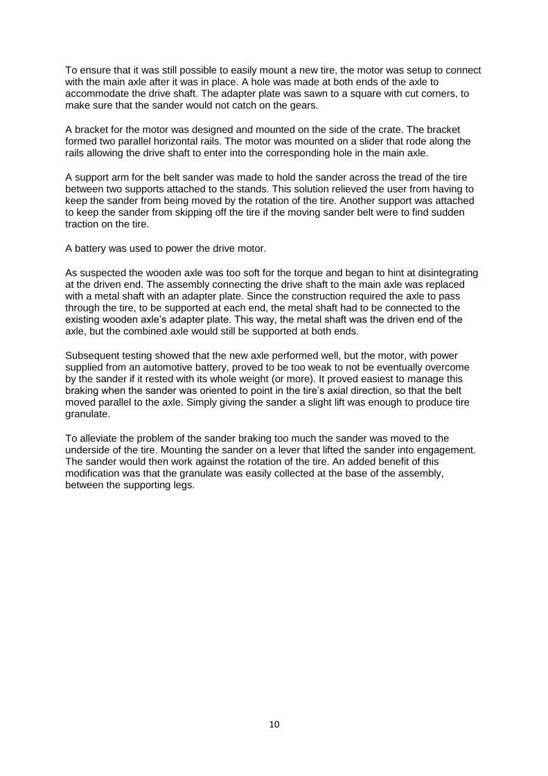
To ensure that it was still possible to easily mount a new tire, the motor was setup to connect with the main axle after it was in place. A hole was made at both ends of the axle to accommodate the drive shaft. The adapter plate was sawn to a square with cut corners, to make sure that the sander would not catch on the gears. A bracket for the motor was designed and mounted on the side of the crate. The bracket formed two parallel horizontal rails. The motor was mounted on a slider that rode along the rails allowing the drive shaft to enter into the corresponding hole in the main axle. A support arm for the belt sander was made to hold the sander across the tread of the tire between two supports attached to the stands. This solution relieved the user from having to keep the sander from being moved by the rotation of the tire. Another support was attached to keep the sander from skipping off the tire if the moving sander belt were to find sudden traction on the tire.
A battery was used to power the drive motor. As suspected the wooden axle was too soft for the torque and began to hint at disintegrating at the driven end. The assembly connecting the drive shaft to the main axle was replaced with a metal shaft with an adapter plate. Since the construction required the axle to pass through the tire, to be supported at each end, the metal shaft had to be connected to the existing wooden axle’s adapter plate. This way, the metal shaft was the driven end of the axle, but the combined axle would still be supported at both ends. Subsequent testing showed that the new axle performed well, but the motor, with power supplied from an automotive battery, proved to be too weak to not be eventually overcome by the sander if it rested with its whole weight (or more). It proved easiest to manage this braking when the sander was oriented to point in the tire’s axial direction, so that the belt moved parallel to the axle. Simply giving the sander a slight lift was enough to produce tire granulate. To alleviate the problem of the sander braking too much the sander was moved to the underside of the tire. Mounting the sander on a lever that lifted the sander into engagement. The sander would then work against the rotation of the tire. An added benefit of this modification was that the granulate was easily collected at the base of the assembly, between the supporting legs.
11
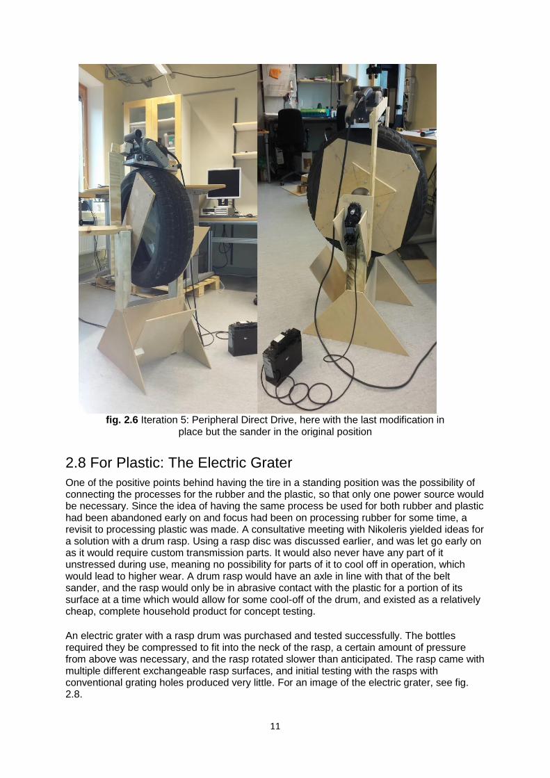
fig. 2.6 Iteration 5: Peripheral Direct Drive, here with the last modification in
place but the sander in the original position
2.8 For Plastic: The Electric Grater One of the positive points behind having the tire in a standing position was the possibility of connecting the processes for the rubber and the plastic, so that only one power source would be necessary. Since the idea of having the same process be used for both rubber and plastic had been abandoned early on and focus had been on processing rubber for some time, a revisit to processing plastic was made. A consultative meeting with Nikoleris yielded ideas for a solution with a drum rasp. Using a rasp disc was discussed earlier, and was let go early on as it would require custom transmission parts. It would also never have any part of it unstressed during use, meaning no possibility for parts of it to cool off in operation, which would lead to higher wear. A drum rasp would have an axle in line with that of the belt sander, and the rasp would only be in abrasive contact with the plastic for a portion of its surface at a time which would allow for some cool-off of the drum, and existed as a relatively cheap, complete household product for concept testing. An electric grater with a rasp drum was purchased and tested successfully. The bottles required they be compressed to fit into the neck of the rasp, a certain amount of pressure from above was necessary, and the rasp rotated slower than anticipated. The rasp came with multiple different exchangeable rasp surfaces, and initial testing with the rasps with conventional grating holes produced very little. For an image of the electric grater, see fig. 2.8.
12
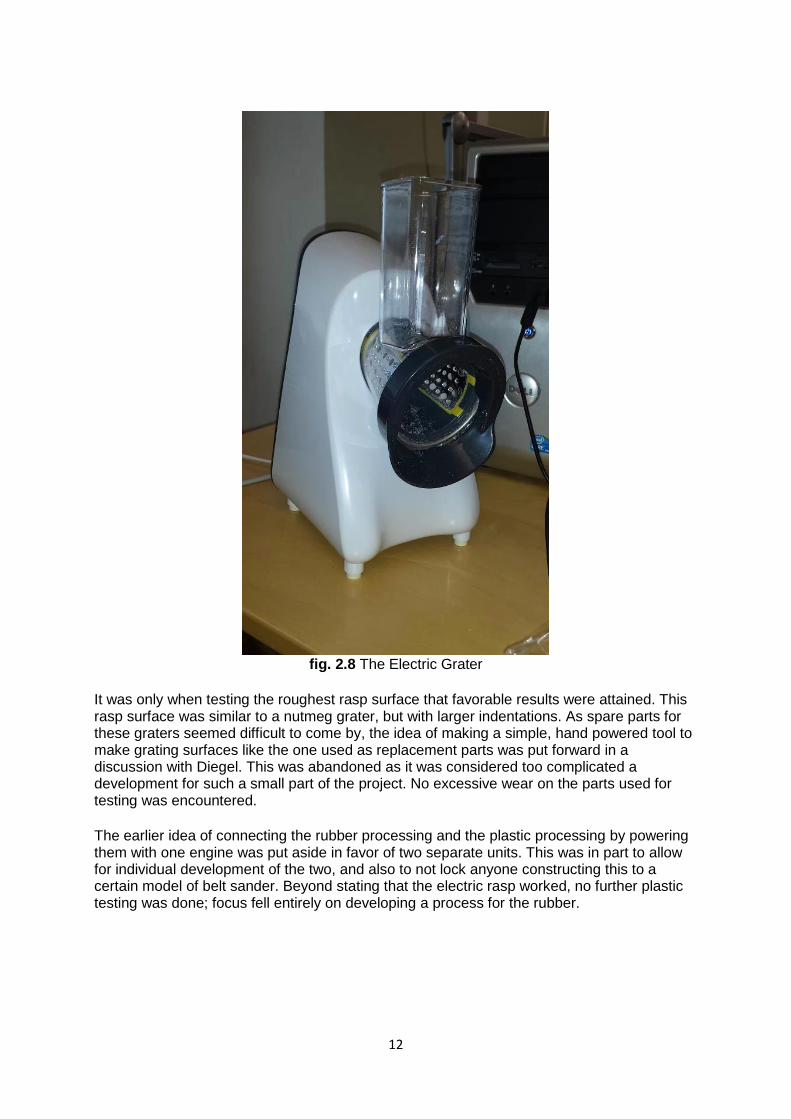
fig. 2.8 The Electric Grater
It was only when testing the roughest rasp surface that favorable results were attained. This rasp surface was similar to a nutmeg grater, but with larger indentations. As spare parts for these graters seemed difficult to come by, the idea of making a simple, hand powered tool to make grating surfaces like the one used as replacement parts was put forward in a discussion with Diegel. This was abandoned as it was considered too complicated a development for such a small part of the project. No excessive wear on the parts used for testing was encountered.
The earlier idea of connecting the rubber processing and the plastic processing by powering them with one engine was put aside in favor of two separate units. This was in part to allow for individual development of the two, and also to not lock anyone constructing this to a certain model of belt sander. Beyond stating that the electric rasp worked, no further plastic testing was done; focus fell entirely on developing a process for the rubber.
13
3 Materials As is described in Engstrand’s report, tires pulverised by sandpaper is fine enough for the printer for which this project is intended to help provide suitable and usable material for. This section describes characteristics of tires and a small range of different thermoplastics from a pulverisation perspective.
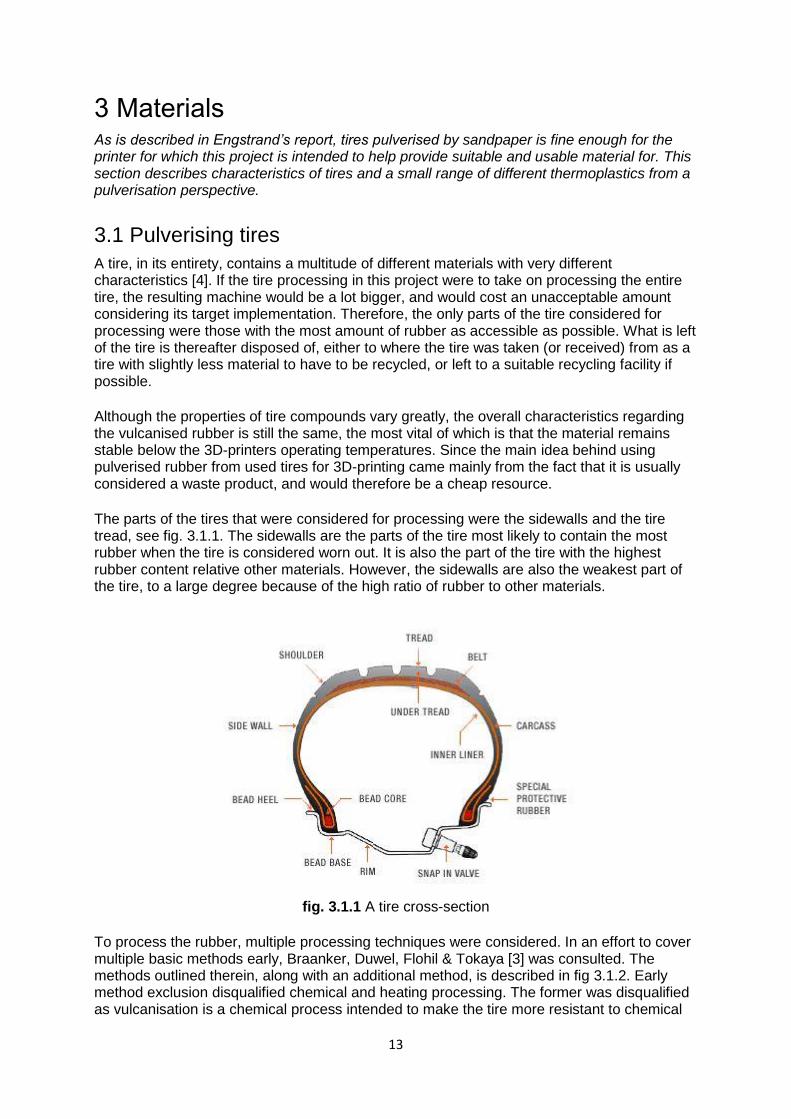
3.1 Pulverising tires A tire, in its entirety, contains a multitude of different materials with very different characteristics [4]. If the tire processing in this project were to take on processing the entire tire, the resulting machine would be a lot bigger, and would cost an unacceptable amount considering its target implementation. Therefore, the only parts of the tire considered for processing were those with the most amount of rubber as accessible as possible. What is left of the tire is thereafter disposed of, either to where the tire was taken (or received) from as a tire with slightly less material to have to be recycled, or left to a suitable recycling facility if possible. Although the properties of tire compounds vary greatly, the overall characteristics regarding the vulcanised rubber is still the same, the most vital of which is that the material remains stable below the 3D-printers operating temperatures. Since the main idea behind using pulverised rubber from used tires for 3D-printing came mainly from the fact that it is usually considered a waste product, and would therefore be a cheap resource. The parts of the tires that were considered for processing were the sidewalls and the tire tread, see fig. 3.1.1. The sidewalls are the parts of the tire most likely to contain the most rubber when the tire is considered worn out. It is also the part of the tire with the highest rubber content relative other materials. However, the sidewalls are also the weakest part of the tire, to a large degree because of the high ratio of rubber to other materials.
fig. 3.1.1 A tire cross-section
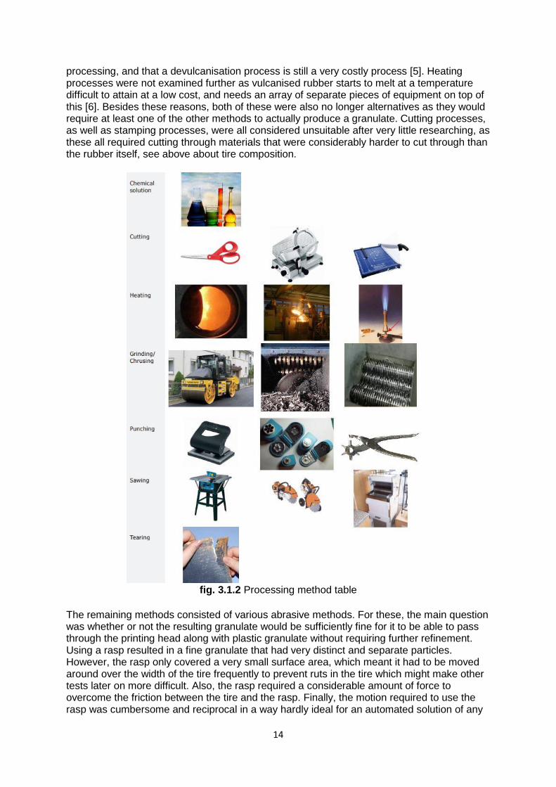
To process the rubber, multiple processing techniques were considered. In an effort to cover multiple basic methods early, Braanker, Duwel, Flohil & Tokaya [3] was consulted. The methods outlined therein, along with an additional method, is described in fig 3.1.2. Early method exclusion disqualified chemical and heating processing. The former was disqualified as vulcanisation is a chemical process intended to make the tire more resistant to chemical
14
processing, and that a devulcanisation process is still a very costly process [5]. Heating processes were not examined further as vulcanised rubber starts to melt at a temperature difficult to attain at a low cost, and needs an array of separate pieces of equipment on top of this [6]. Besides these reasons, both of these were also no longer alternatives as they would require at least one of the other methods to actually produce a granulate. Cutting processes, as well as stamping processes, were all considered unsuitable after very little researching, as these all required cutting through materials that were considerably harder to cut through than the rubber itself, see above about tire composition.
fig. 3.1.2 Processing method table
The remaining methods consisted of various abrasive methods. For these, the main question was whether or not the resulting granulate would be sufficiently fine for it to be able to pass through the printing head along with plastic granulate without requiring further refinement. Using a rasp resulted in a fine granulate that had very distinct and separate particles. However, the rasp only covered a very small surface area, which meant it had to be moved around over the width of the tire frequently to prevent ruts in the tire which might make other tests later on more difficult. Also, the rasp required a considerable amount of force to overcome the friction between the tire and the rasp. Finally, the motion required to use the rasp was cumbersome and reciprocal in a way hardly ideal for an automated solution of any
15
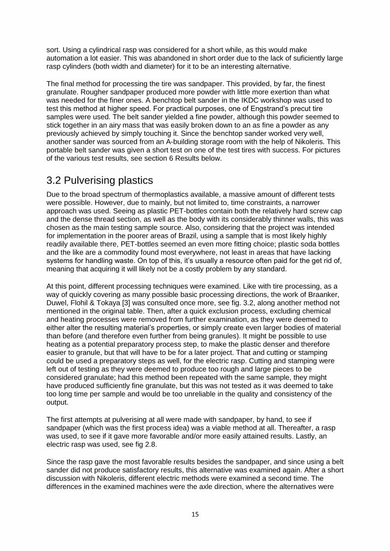
sort. Using a cylindrical rasp was considered for a short while, as this would make automation a lot easier. This was abandoned in short order due to the lack of suficiently large rasp cylinders (both width and diameter) for it to be an interesting alternative. The final method for processing the tire was sandpaper. This provided, by far, the finest granulate. Rougher sandpaper produced more powder with little more exertion than what was needed for the finer ones. A benchtop belt sander in the IKDC workshop was used to test this method at higher speed. For practical purposes, one of Engstrand’s precut tire samples were used. The belt sander yielded a fine powder, although this powder seemed to stick together in an airy mass that was easily broken down to an as fine a powder as any previously achieved by simply touching it. Since the benchtop sander worked very well, another sander was sourced from an A-building storage room with the help of Nikoleris. This portable belt sander was given a short test on one of the test tires with success. For pictures of the various test results, see section 6 Results below.
3.2 Pulverising plastics Due to the broad spectrum of thermoplastics available, a massive amount of different tests were possible. However, due to mainly, but not limited to, time constraints, a narrower approach was used. Seeing as plastic PET-bottles contain both the relatively hard screw cap and the dense thread section, as well as the body with its considerably thinner walls, this was chosen as the main testing sample source. Also, considering that the project was intended for implementation in the poorer areas of Brazil, using a sample that is most likely highly readily available there, PET-bottles seemed an even more fitting choice; plastic soda bottles and the like are a commodity found most everywhere, not least in areas that have lacking systems for handling waste. On top of this, it’s usually a resource often paid for the get rid of, meaning that acquiring it will likely not be a costly problem by any standard. At this point, different processing techniques were examined. Like with tire processing, as a way of quickly covering as many possible basic processing directions, the work of Braanker, Duwel, Flohil & Tokaya [3] was consulted once more, see fig. 3.2, along another method not mentioned in the original table. Then, after a quick exclusion process, excluding chemical and heating processes were removed from further examination, as they were deemed to either alter the resulting material’s properties, or simply create even larger bodies of material than before (and therefore even further from being granules). It might be possible to use heating as a potential preparatory process step, to make the plastic denser and therefore easier to granule, but that will have to be for a later project. That and cutting or stamping could be used a preparatory steps as well, for the electric rasp. Cutting and stamping were left out of testing as they were deemed to produce too rough and large pieces to be considered granulate; had this method been repeated with the same sample, they might have produced sufficiently fine granulate, but this was not tested as it was deemed to take too long time per sample and would be too unreliable in the quality and consistency of the output. The first attempts at pulverising at all were made with sandpaper, by hand, to see if sandpaper (which was the first process idea) was a viable method at all. Thereafter, a rasp was used, to see if it gave more favorable and/or more easily attained results. Lastly, an electric rasp was used, see fig 2.8. Since the rasp gave the most favorable results besides the sandpaper, and since using a belt sander did not produce satisfactory results, this alternative was examined again. After a short discussion with Nikoleris, different electric methods were examined a second time. The differences in the examined machines were the axle direction, where the alternatives were
16
either a vertical axle or a horizontal axle. An electric rasp with a horizontal axle was chosen and bought. For more on the reasoning behind this selection, see section 2.4 above.
3.2.1
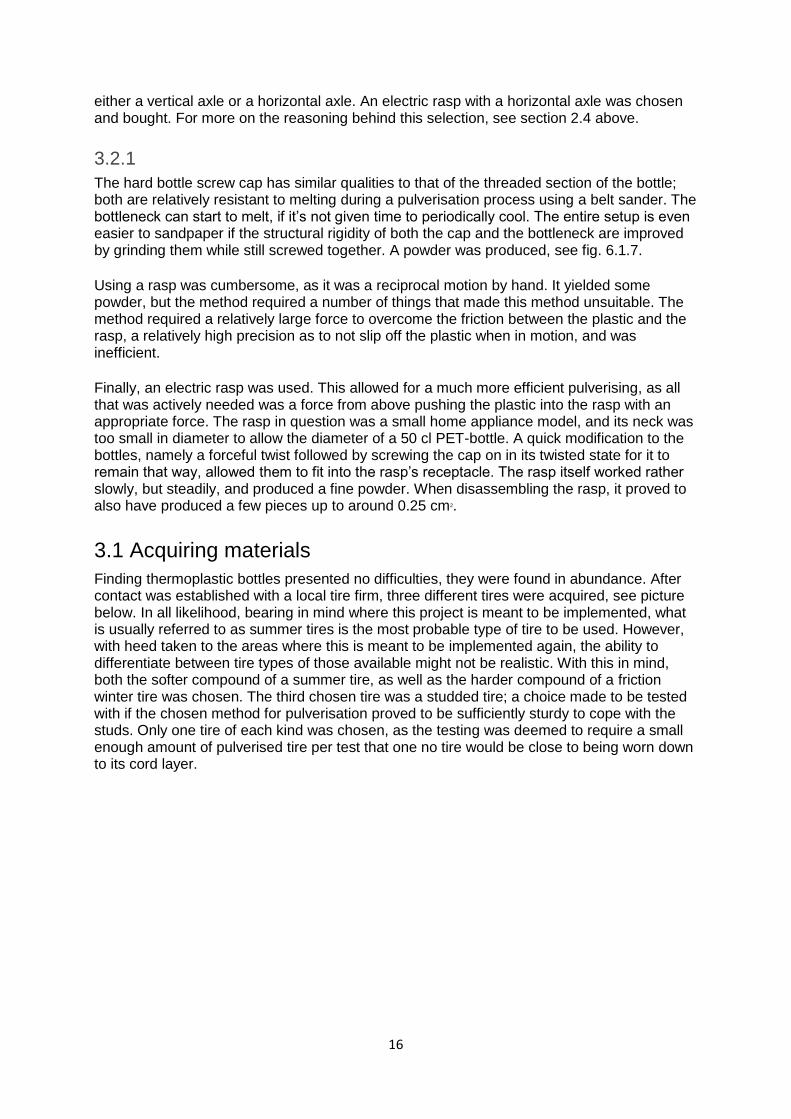
The hard bottle screw cap has similar qualities to that of the threaded section of the bottle; both are relatively resistant to melting during a pulverisation process using a belt sander. The bottleneck can start to melt, if it’s not given time to periodically cool. The entire setup is even easier to sandpaper if the structural rigidity of both the cap and the bottleneck are improved by grinding them while still screwed together. A powder was produced, see fig. 6.1.7. Using a rasp was cumbersome, as it was a reciprocal motion by hand. It yielded some powder, but the method required a number of things that made this method unsuitable. The method required a relatively large force to overcome the friction between the plastic and the rasp, a relatively high precision as to not slip off the plastic when in motion, and was inefficient. Finally, an electric rasp was used. This allowed for a much more efficient pulverising, as all that was actively needed was a force from above pushing the plastic into the rasp with an appropriate force. The rasp in question was a small home appliance model, and its neck was too small in diameter to allow the diameter of a 50 cl PET-bottle. A quick modification to the bottles, namely a forceful twist followed by screwing the cap on in its twisted state for it to remain that way, allowed them to fit into the rasp’s receptacle. The rasp itself worked rather slowly, but steadily, and produced a fine powder. When disassembling the rasp, it proved to also have produced a few pieces up to around 0.25 cm2.
3.1 Acquiring materials Finding thermoplastic bottles presented no difficulties, they were found in abundance. After contact was established with a local tire firm, three different tires were acquired, see picture below. In all likelihood, bearing in mind where this project is meant to be implemented, what is usually referred to as summer tires is the most probable type of tire to be used. However, with heed taken to the areas where this is meant to be implemented again, the ability to differentiate between tire types of those available might not be realistic. With this in mind, both the softer compound of a summer tire, as well as the harder compound of a friction winter tire was chosen. The third chosen tire was a studded tire; a choice made to be tested with if the chosen method for pulverisation proved to be sufficiently sturdy to cope with the studs. Only one tire of each kind was chosen, as the testing was deemed to require a small enough amount of pulverised tire per test that one no tire would be close to being worn down to its cord layer.
17
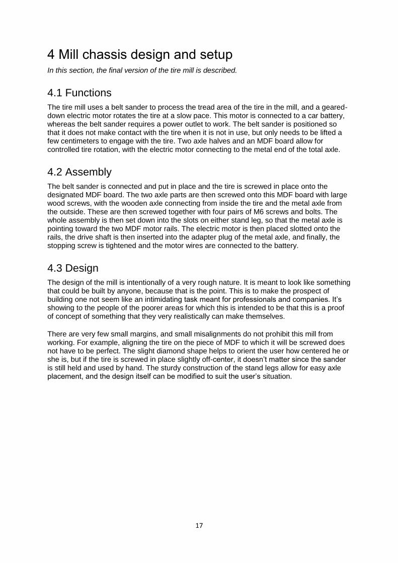
4 Mill chassis design and setup In this section, the final version of the tire mill is described.
4.1 Functions The tire mill uses a belt sander to process the tread area of the tire in the mill, and a geared-down electric motor rotates the tire at a slow pace. This motor is connected to a car battery, whereas the belt sander requires a power outlet to work. The belt sander is positioned so that it does not make contact with the tire when it is not in use, but only needs to be lifted a few centimeters to engage with the tire. Two axle halves and an MDF board allow for controlled tire rotation, with the electric motor connecting to the metal end of the total axle.
4.2 Assembly The belt sander is connected and put in place and the tire is screwed in place onto the designated MDF board. The two axle parts are then screwed onto this MDF board with large wood screws, with the wooden axle connecting from inside the tire and the metal axle from the outside. These are then screwed together with four pairs of M6 screws and bolts. The whole assembly is then set down into the slots on either stand leg, so that the metal axle is pointing toward the two MDF motor rails. The electric motor is then placed slotted onto the rails, the drive shaft is then inserted into the adapter plug of the metal axle, and finally, the stopping screw is tightened and the motor wires are connected to the battery.
4.3 Design The design of the mill is intentionally of a very rough nature. It is meant to look like something that could be built by anyone, because that is the point. This is to make the prospect of building one not seem like an intimidating task meant for professionals and companies. It’s showing to the people of the poorer areas for which this is intended to be that this is a proof of concept of something that they very realistically can make themselves. There are very few small margins, and small misalignments do not prohibit this mill from working. For example, aligning the tire on the piece of MDF to which it will be screwed does not have to be perfect. The slight diamond shape helps to orient the user how centered he or she is, but if the tire is screwed in place slightly off-center, it doesn’t matter since the sander is still held and used by hand. The sturdy construction of the stand legs allow for easy axle placement, and the design itself can be modified to suit the user’s situation.
18
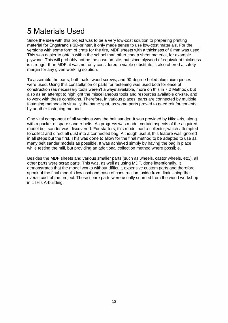
5 Materials Used Since the idea with this project was to be a very low-cost solution to preparing printing material for Engstrand’s 3D-printer, it only made sense to use low-cost materials. For the versions with some form of crate for the tire, MDF sheets with a thickness of 6 mm was used. This was easier to obtain within the school than other cheap sheet material, for example plywood. This will probably not be the case on-site, but since plywood of equivalent thickness is stronger than MDF, it was not only considered a viable substitute; it also offered a safety margin for any given working solution. To assemble the parts, both nails, wood screws, and 90-degree holed aluminium pieces were used. Using this constellation of parts for fastening was used both for ease of construction (as necessary tools weren’t always available, more on this in 7.2 Method), but also as an attempt to highlight the miscellaneous tools and resources available on-site, and to work with these conditions. Therefore, in various places, parts are connected by multiple fastening methods in virtually the same spot, as some parts proved to need reinforcements by another fastening method. One vital component of all versions was the belt sander. It was provided by Nikoleris, along with a packet of spare sander belts. As progress was made, certain aspects of the acquired model belt sander was discovered. For starters, this model had a collector, which attempted to collect and direct all dust into a connected bag. Although useful, this feature was ignored in all steps but the first. This was done to allow for the final method to be adapted to use as many belt sander models as possible. It was achieved simply by having the bag in place while testing the mill, but providing an additional collection method where possible. Besides the MDF sheets and various smaller parts (such as wheels, castor wheels, etc.), all other parts were scrap parts. This was, as well as using MDF, done intentionally. It demonstrates that the model works without difficult, expensive custom parts and therefore speak of the final model’s low cost and ease of construction, aside from diminishing the overall cost of the project. These spare parts were usually sourced from the wood workshop in LTH’s A-building.
19
6 Final Results The results gathered from testing the materials are described below. The results from the development process are also described in this section as well.
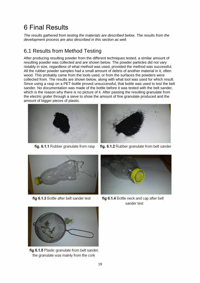
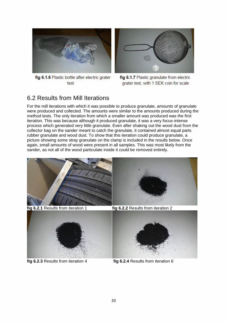
6.1 Results from Method Testing After producing resulting powder from the different techniques tested, a similar amount of resulting powder was collected and are shown below. The powder particles did not vary notably in size, regardless of what method was used, provided the method was successful. All the rubber powder samples had a small amount of debris of another material in it, often wood. This probably came from the tools used, or from the surfaces the powders were collected from. The results are shown below, along with what tool was used for which result. Since using a rasp on a PET-bottle proved unsuccessful, that bottle was used to test the belt sander. No documentation was made of the bottle before it was tested with the belt sander, which is the reason why there is no picture of it. After passing the resulting granulate from the electric grater through a sieve to show the amount of fine granulate produced and the amount of bigger pieces of plastic.
20
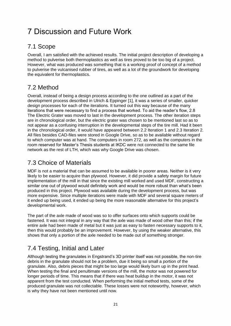
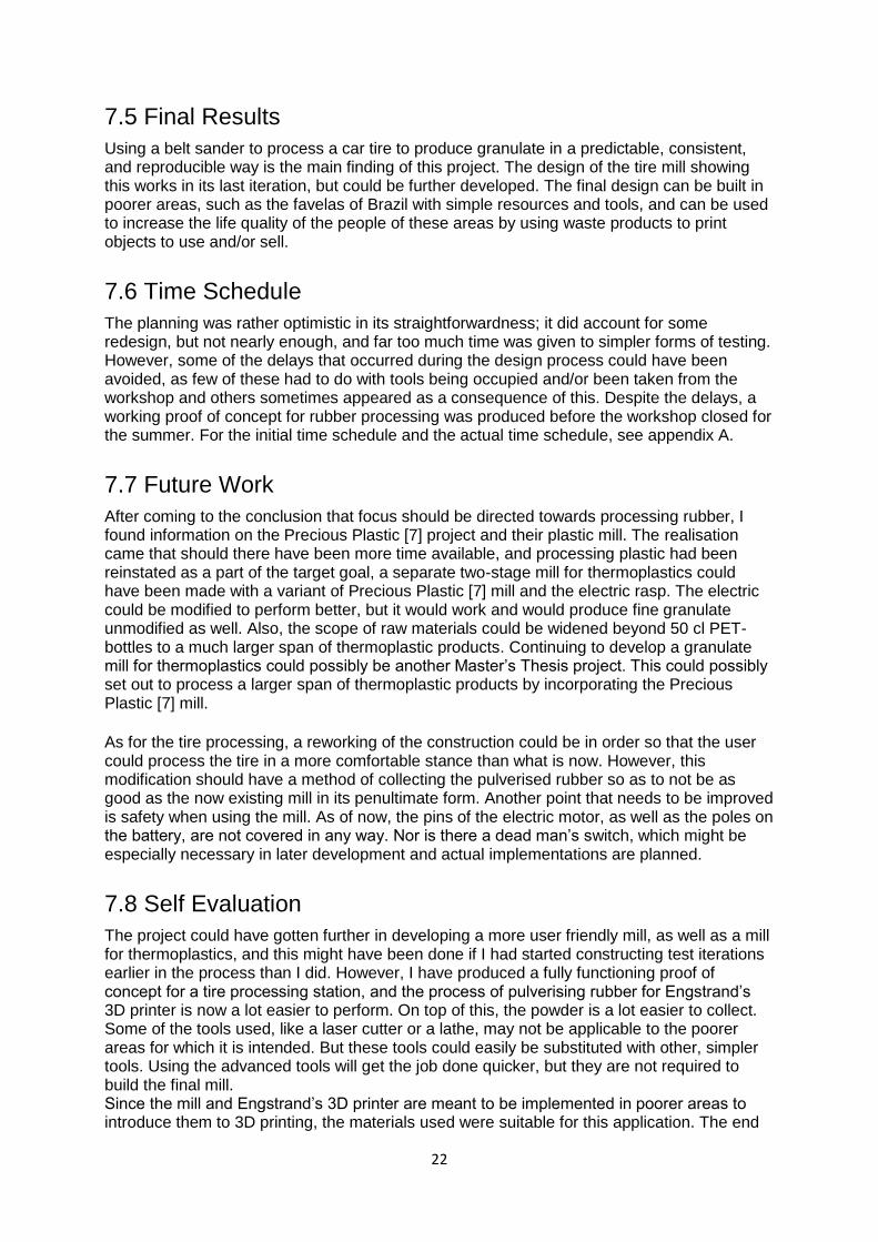
6.2 Results from Mill Iterations For the mill iterations with which it was possible to produce granulate, amounts of granulate were produced and collected. The amounts were similar to the amounts produced during the method tests. The only iteration from which a smaller amount was produced was the first iteration. This was because although it produced granulate, it was a very focus-intense process which generated very little granulate. Even after shaking out the wood dust from the collector bag on the sander meant to catch the granulate, it contained almost equal parts rubber granulate and wood dust. To show that this iteration could produce granulate, a picture showing some stray granulate on the clamp is included in the results below. Once again, small amounts of wood were present in all samples. This was most likely from the sander, as not all of the wood particulate inside it could be removed entirely.
fig 6.2.1 Results from iteration 1 fig 6.2.2 Results from iteration 2
fig 6.2.3 Results from iteration 4 fig 6.2.4 Results from iteration 6
21
7 Discussion and Future Work
7.1 Scope Overall, I am satisfied with the achieved results. The initial project description of developing a method to pulverise both thermoplastics as well as tires proved to be too big of a project. However, what was produced was something that is a working proof of concept of a method to pulverise the vulcanised rubber of tires, as well as a lot of the groundwork for developing the equivalent for thermoplastics.
7.2 Method Overall, instead of being a design process according to the one outlined as a part of the development process described in Ulrich & Eppinger [1], it was a series of smaller, quicker design processes for each of the iterations. It turned out this way because of the many iterations that were necessary to find a process that worked. To aid the reader’s flow, 2.8 The Electric Grater was moved to last in the development process. The other iteration steps are in chronological order, but the electric grater was chosen to be mentioned last so as to not appear as a confusing interruption in the developmental steps of the tire mill. Had it been in the chronological order, it would have appeared between 2.2 Iteration 1 and 2.3 Iteration 2. All files besides CAD-files were stored in Google Drive, so as to be available without regard to which computer was at hand. The computers in room 272, as well as the computers in the room reserved for Master’s Thesis students at IKDC were not connected to the same file network as the rest of LTH, which was why Google Drive was chosen.
7.3 Choice of Materials MDF is not a material that can be assumed to be available in poorer areas. Neither is it very likely to be easier to acquire than plywood. However, it did provide a safety margin for future implementation of the mill in that since the existing mill worked and used MDF, constructing a similar one out of plywood would definitely work and would be more robust than what’s been produced in this project. Plywood was available during the development process, but was more expensive. Since multiple iterations were made with MDF and several square meters of it ended up being used, it ended up being the more reasonable alternative for this project’s developmental work. The part of the axle made of wood was so to offer surfaces onto which supports could be fastened. It was not integral in any way that the axle was made of wood other than this; if the entire axle had been made of metal but it was just as easy to fasten necessary supports to it, then this would probably be an improvement. However, by using the weaker alternative, this shows that only a portion of the axle needed to be made out of something stronger.
7.4 Testing, Initial and Later Although testing the granulates in Engstrand’s 3D printer itself was not possible, the non-tire debris in the granulate should not be a problem, due it being so small a portion of the granulate. Also, debris pieces that might be too large would likely burn up in the print head. When testing the final and penultimate versions of the mill, the motor was not powered for longer periods of time. This means that if there was heat buildup in the motor, it was not apparent from the test conducted. When performing the initial method tests, some of the produced granulate was not collectable. These losses were not noteworthy, however, which is why they have not been mentioned until now.
22
7.5 Final Results Using a belt sander to process a car tire to produce granulate in a predictable, consistent, and reproducible way is the main finding of this project. The design of the tire mill showing this works in its last iteration, but could be further developed. The final design can be built in poorer areas, such as the favelas of Brazil with simple resources and tools, and can be used to increase the life quality of the people of these areas by using waste products to print objects to use and/or sell.
7.6 Time Schedule The planning was rather optimistic in its straightforwardness; it did account for some redesign, but not nearly enough, and far too much time was given to simpler forms of testing. However, some of the delays that occurred during the design process could have been avoided, as few of these had to do with tools being occupied and/or been taken from the workshop and others sometimes appeared as a consequence of this. Despite the delays, a working proof of concept for rubber processing was produced before the workshop closed for the summer. For the initial time schedule and the actual time schedule, see appendix A.
7.7 Future Work After coming to the conclusion that focus should be directed towards processing rubber, I found information on the Precious Plastic [7] project and their plastic mill. The realisation came that should there have been more time available, and processing plastic had been reinstated as a part of the target goal, a separate two-stage mill for thermoplastics could have been made with a variant of Precious Plastic [7] mill and the electric rasp. The electric could be modified to perform better, but it would work and would produce fine granulate unmodified as well. Also, the scope of raw materials could be widened beyond 50 cl PET-bottles to a much larger span of thermoplastic products. Continuing to develop a granulate mill for thermoplastics could possibly be another Master’s Thesis project. This could possibly set out to process a larger span of thermoplastic products by incorporating the Precious Plastic [7] mill. As for the tire processing, a reworking of the construction could be in order so that the user could process the tire in a more comfortable stance than what is now. However, this modification should have a method of collecting the pulverised rubber so as to not be as good as the now existing mill in its penultimate form. Another point that needs to be improved is safety when using the mill. As of now, the pins of the electric motor, as well as the poles on the battery, are not covered in any way. Nor is there a dead man’s switch, which might be especially necessary in later development and actual implementations are planned.
7.8 Self Evaluation The project could have gotten further in developing a more user friendly mill, as well as a mill for thermoplastics, and this might have been done if I had started constructing test iterations earlier in the process than I did. However, I have produced a fully functioning proof of concept for a tire processing station, and the process of pulverising rubber for Engstrand’s 3D printer is now a lot easier to perform. On top of this, the powder is a lot easier to collect. Some of the tools used, like a laser cutter or a lathe, may not be applicable to the poorer areas for which it is intended. But these tools could easily be substituted with other, simpler tools. Using the advanced tools will get the job done quicker, but they are not required to build the final mill. Since the mill and Engstrand’s 3D printer are meant to be implemented in poorer areas to introduce them to 3D printing, the materials used were suitable for this application. The end

23
result proved the principle of being able to produce tire granulate from car tires with the help of a belt sander to process the tire and an electric motor to rotate it. The development process yielded a possible design for showing this principle. In its implementation, the exact construction of the mill could vary, depending on the resources available, but the technique of using a belt sander and an electric motor would still work. This is the main conclusion of this project. This project has been a valuable experience, and while it showed once more that progress is made even when the desired results are not achieved, it also presented a challenge that was met and conquered.
24
References