Embed Size (px)
Citation preview
Development of FFRCT
Charles A. Taylor, Ph.D.
FFRCT
Founder, Chief Technology OfficerHeartFlow, Inc.
Consulting Professor of BioengineeringStanford University
January 6, 2012
TMP‐100‐012‐A
DisclosuresDisclosures
• Founder, Shareholder and Employee of HeartFlow, Inc.
2
HeartFlow Company OverviewHeartFlow Company Overview
• Computational fluid dynamics applied to cardiac CT N i i t f h d iscans - Non-invasive assessment of hemodynamic
significance of coronary artery lesions
• HeartFlow Inc founded in 2007 by Charles A Taylor• HeartFlow, Inc. founded in 2007 by Charles A. Taylor, Ph.D. and Christopher K. Zarins, M.D. based on technology developed in their labs at Stanford Universitytechnology developed in their labs at Stanford University
• HeartFlow team led by John H. Stevens, M.D., Chairman and CEO
• 103 patient, First-in-man DISCOVER-FLOW study published in JACC (Koo et al. 2011)
• 17 center, 285 patient prospective clinical trial (DeFACTO) will be completed imminently
3
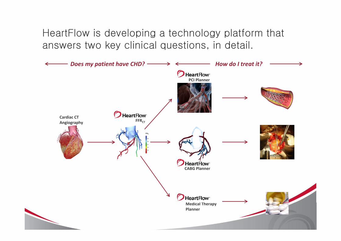
HeartFlow is developing a technology platform that answers two key clinical questions, in detail.
Does my patient have CHD? How do I treat it?
PCI Planner
Does my patient have CHD? How do I treat it?
FFRCardiac CT
FFRCTAngiography
CABG Planner
M di l ThMedical Therapy Planner
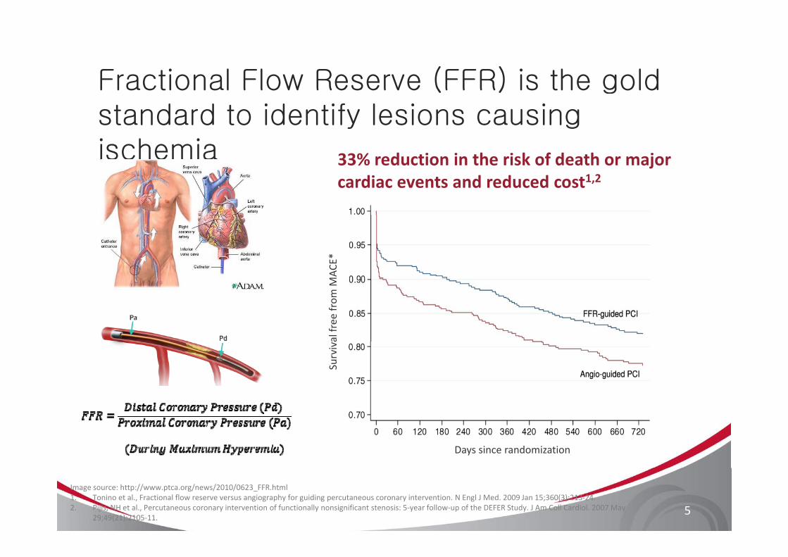
Fractional Flow Reserve (FFR) is the goldFractional Flow Reserve (FFR) is the gold standard to identify lesions causing ischemiaischemia 33% reduction in the risk of death or major
cardiac events and reduced cost1,2
MAC
E*al free
from
MSurviv
Days since randomization
5
Image source: http://www.ptca.org/news/2010/0623_FFR.html1. Tonino et al., Fractional flow reserve versus angiography for guiding percutaneous coronary intervention. N Engl J Med. 2009 Jan 15;360(3):213‐24. 2. Pijls, NH et al., Percutaneous coronary intervention of functionally nonsignificant stenosis: 5‐year follow‐up of the DEFER Study. J Am Coll Cardiol. 2007 May
29;49(21):2105‐11.
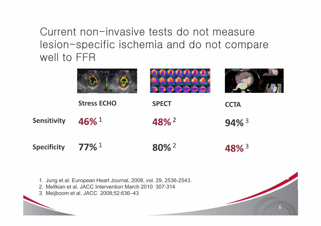
Current non-invasive tests do not measure lesion-specific ischemia and do not compare well to FFR
Stress ECHO CCTASPECT
46% 1 94% 348% 2Sensitivity
77% 1 48% 380% 2Specificity
1. Jung et al. European Heart Journal, 2008, vol. 29, 2536-2543.2. Mellkian et al. JACC Intervention March 2010 307-314
6
3. Meijboom et al. JACC 2008;52:636–43
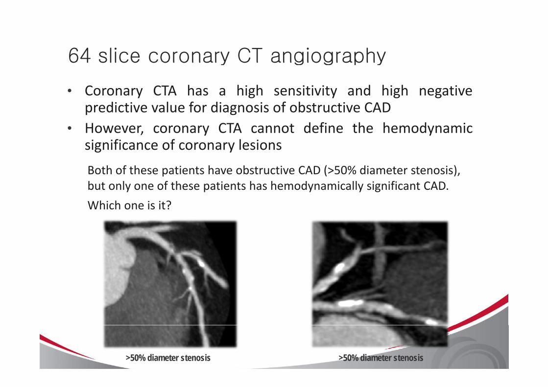
64 slice coronary CT angiography64 slice coronary CT angiography
• Coronary CTA has a high sensitivity and high negativepredictive value for diagnosis of obstructive CADpredictive value for diagnosis of obstructive CAD
• However, coronary CTA cannot define the hemodynamicsignificance of coronary lesionssignificance of coronary lesions
Both of these patients have obstructive CAD (>50% diameter stenosis), but only one of these patients has hemodynamically significant CAD.
Which one is it?
>50% diameter stenosis >50% diameter stenosis
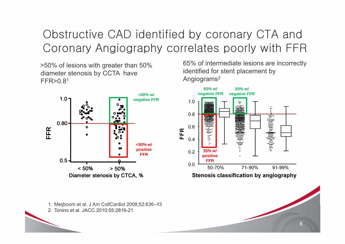
Obstructive CAD identified by coronary CTA and y yCoronary Angiography correlates poorly with FFR
>50% of lesions with greater than 50% 65% of intermediate lesions are incorrectly >50% of lesions with greater than 50% diameter stenosis by CCTA have FFR>0.81
yidentified for stent placement by Angiograms2
65% w/ negative FFR>50% w/
20% w/ negative FFRnegative FFR>50% w/
negative FFRnegative FFR
FFR
35% /<50% w/ positive 35% w/
positive FFR
positive FFR
1 Meijboom et al J Am CollCardiol 2008;52:636–43
8
1. Meijboom et al. J Am CollCardiol 2008;52:636 432. Tonino et al. JACC 2010;55:2816-21
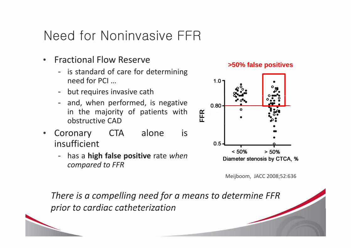
Need for Noninvasive FFRNeed for Noninvasive FFR
• Fractional Flow Reserve >50% false positives- is standard of care for determining
need for PCI …- but requires invasive cath
p
- and, when performed, is negativein the majority of patients withobstructive CAD FF
R
• Coronary CTA alone isinsufficient- has a high false positive rate when
compared to FFRMeijboom, JACC 2008;52:636
There is a compelling need for a means to determine FFR prior to cardiac catheterizationprior to cardiac catheterization
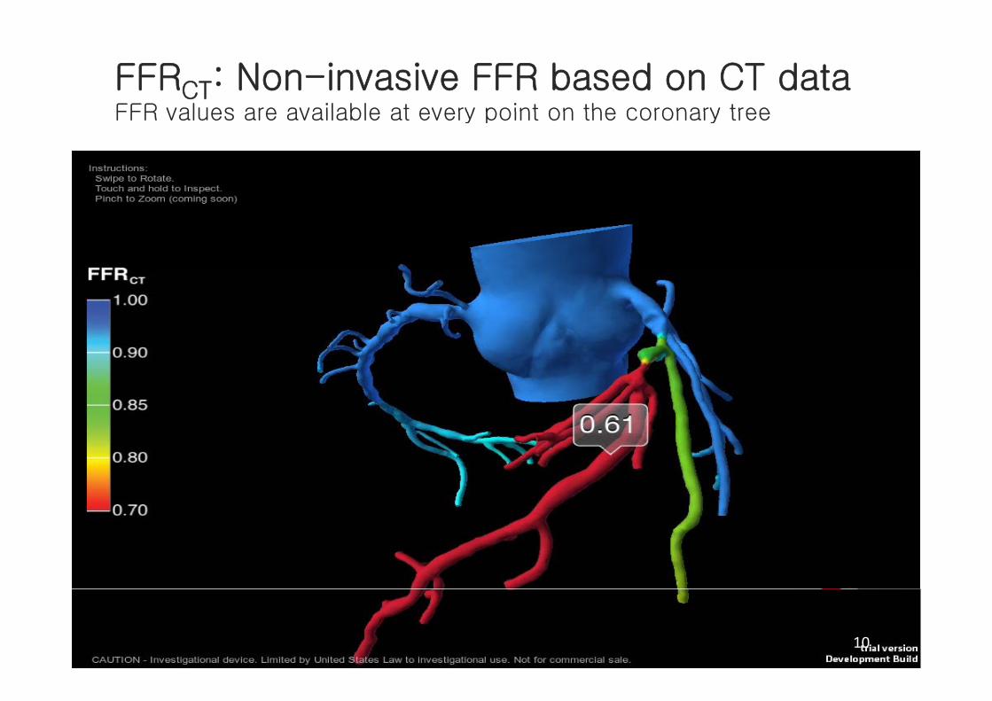
FFRCT: Non-invasive FFR based on CT dataFFR values are available at every point on the coronary treeFFR values are available at every point on the coronary tree
10
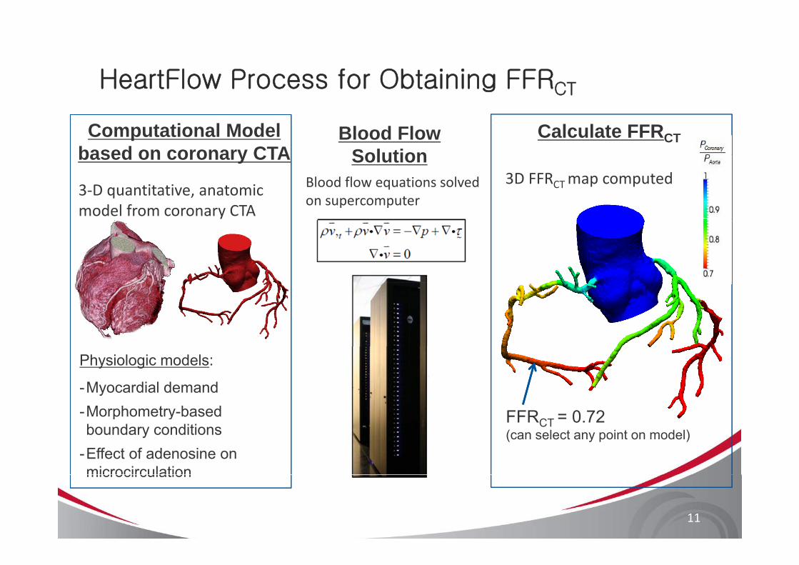
HeartFlow Process for Obtaining FFRCTg CT
Computational Model based on coronary CTA
Blood Flow Solution
Calculate FFRCT
3‐D quantitative, anatomic model from coronary CTA
Blood flow equations solved on supercomputer
3D FFRCT map computedbased on coronary CTA Solution
y
Physiologic models:
-Myocardial demandMorphometry based FFR 0 72-Morphometry-based boundary conditions
-Effect of adenosine on microcirculation
FFRCT = 0.72(can select any point on model)
11
microcirculation
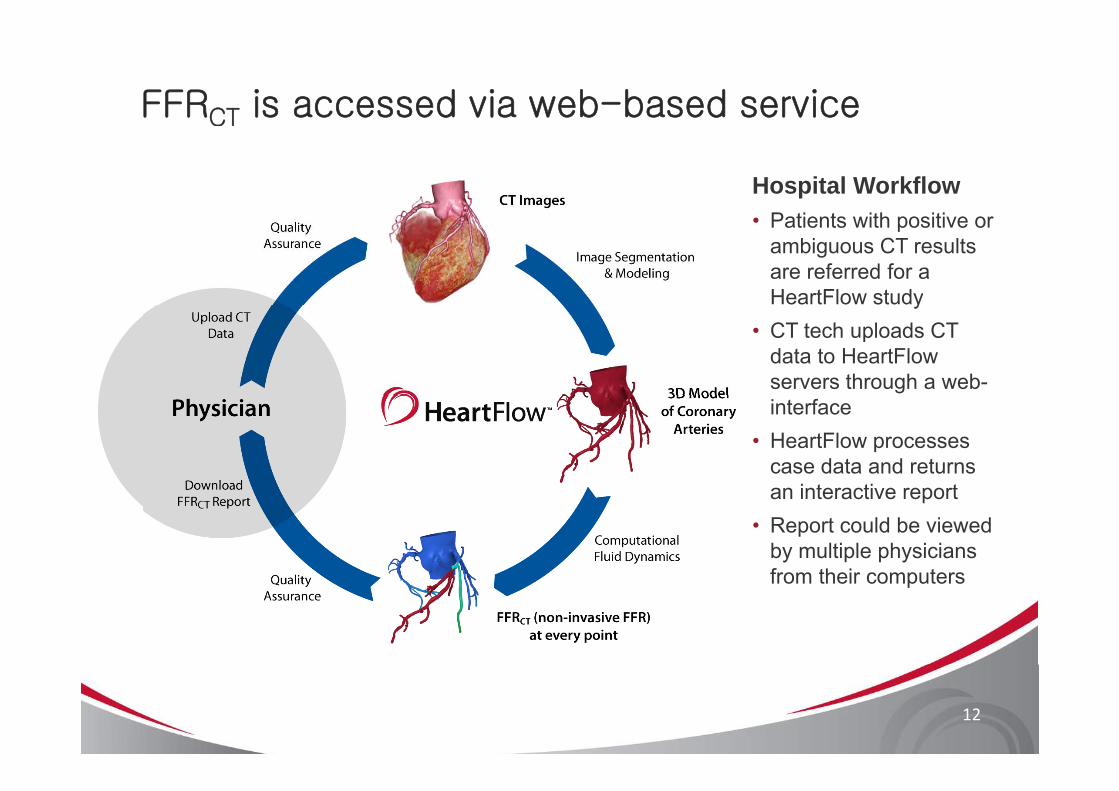
FFRCT is accessed via web-based service
Hospital WorkflowP ti t ith iti• Patients with positive or ambiguous CT results are referred for a HeartFlow studyy
• CT tech uploads CT data to HeartFlow servers through a web-interface
• HeartFlow processes case data and returns
i t ti tan interactive report• Report could be viewed
by multiple physicians from their computersfrom their computers
12
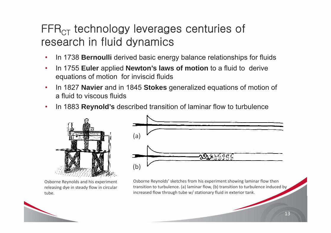
FFRCT technology leverages centuries of research in fluid dynamics
• In 1738 Bernoulli derived basic energy balance relationships for fluids• In 1755 Euler applied Newton’s laws of motion to a fluid to derive
equations of motion for inviscid fluids• In 1827 Navier and in 1845 Stokes generalized equations of motion of g q
a fluid to viscous fluids• In 1883 Reynold’s described transition of laminar flow to turbulence
(a)
(b)
Osborne Reynolds and his experiment releasing dye in steady flow in circular tube.
Osborne Reynolds’ sketches from his experiment showing laminar flow then transition to turbulence. (a) laminar flow, (b) transition to turbulence induced by increased flow through tube w/ stationary fluid in exterior tank.
( )
13
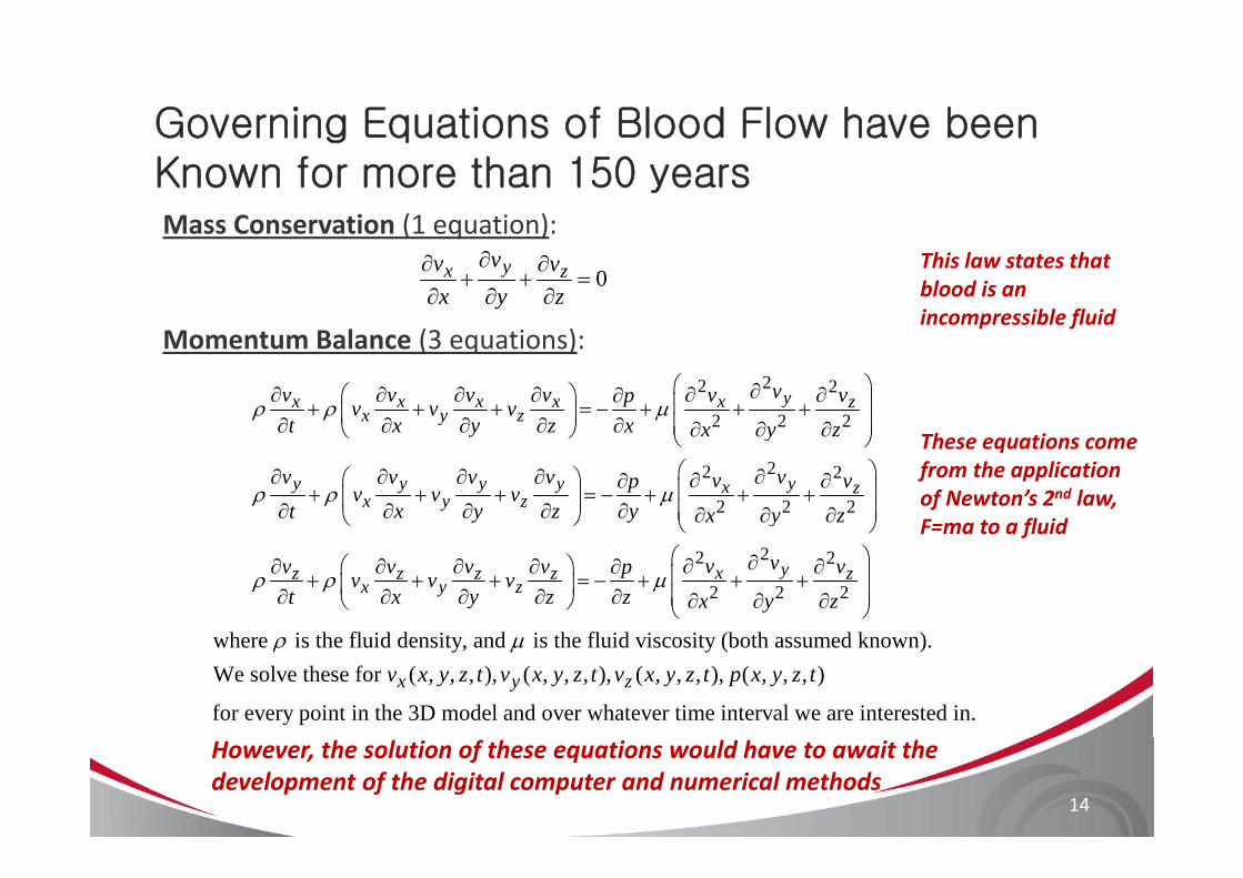
Governing Equations of Blood Flow have been
Mass Conservation (1 equation):
g qKnown for more than 150 years
Momentum Balance (3 equations):
0∂∂ ∂
+ + =∂ ∂ ∂
yx zvv vx y z
This law states thatblood is an incompressible fluid
Momentum Balance (3 equations):22 2
2 2 2
⎛ ⎞∂⎛ ⎞∂ ∂ ∂ ∂ ∂ ∂∂ ⎜ ⎟+ + + = − + + +⎜ ⎟∂ ∂ ∂ ∂ ∂ ⎜ ⎟∂ ∂ ∂⎝ ⎠ ⎝ ⎠
yx x x x x zx y z
vv v v v v vpv v vt x y z x x y z
ρ ρ μThese equations come
22 2
2 2 2
⎝ ⎠⎛ ⎞∂ ∂ ∂ ∂ ∂⎛ ⎞ ∂ ∂∂ ⎜ ⎟+ + + = − + + +⎜ ⎟∂ ∂ ∂ ∂ ∂ ⎜ ⎟∂ ∂ ∂⎝ ⎠ ⎝ ⎠
y y y y yx zx y z
y
v v v v vv vpv v vt x y z y x y z
ρ ρ μ
These equations come from the application of Newton’s 2nd law, F=ma to a fluid
2⎛ ⎞ ∂∂ ∂ ∂ ∂ ∂+ + + = − +⎜ ⎟∂ ∂ ∂ ∂ ∂⎝ ⎠
z z z zx y z
vv v v v pv v vt x y z z
ρ ρ μ2 2
2 2 2
⎛ ⎞∂ ∂⎜ ⎟+ +⎜ ⎟∂ ∂ ∂⎝ ⎠
yx zv vx y z
where is the fluid density and is the fluid viscosity (both assumed known)ρ μwhere is the fluid density, and is the fluid viscosity (both assumed known).We solve these for ( , , , ), ( , , , ), ( , , , ), ( , , , )
for every point in the 3D model and over whatever time x y zv x y z t v x y z t v x y z t p x y z t
ρ μ
interval we are interested in.
14
However, the solution of these equations would have to await the development of the digital computer and numerical methods

FFRCT technology leverages 50 years of CT gy g yResearch in Computational Fluid Dynamics
Computational fluid dynamics (CFD) quantifies fluidComputational fluid dynamics (CFD) quantifies fluidpressure and velocity, based on physical laws of massconservation and momentum balance and is widely used inythe aerospace and automotive industries for design andtesting
HeartFlow applies CFD to solve problems of human coronary blood flowImages courtesy of Prof. Charbel Farhat, Dept. of Aeronautics & Astronautics, Stanford University
15
HeartFlow applies CFD to solve problems of human coronary blood flow
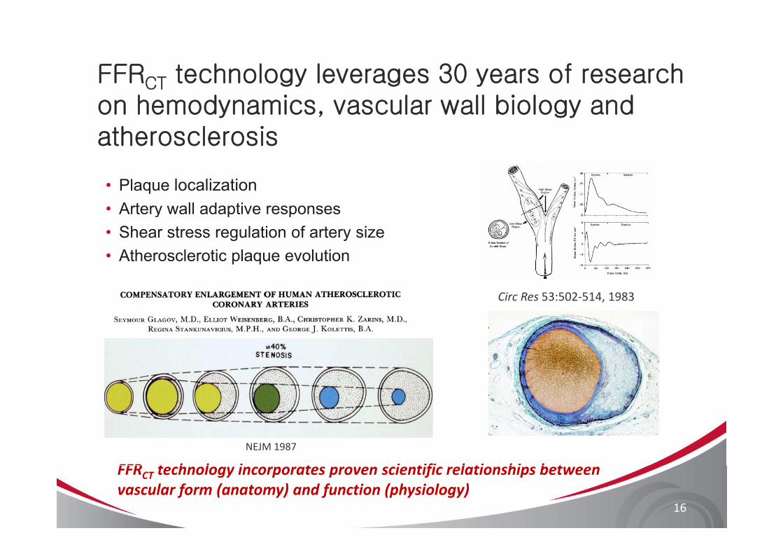
FFRCT technology leverages 30 years of research CT
on hemodynamics, vascular wall biology and atherosclerosis
• Plaque localization• Artery wall adaptive responseste y a adapt e espo ses• Shear stress regulation of artery size• Atherosclerotic plaque evolution
Circ Res 53:502‐514, 1983
NEJM 1987
FFR t h l i t i tifi l ti hi b t
16
FFRCT technology incorporates proven scientific relationships between vascular form (anatomy) and function (physiology)

FFRCT technology based on 15 years of research i ifi 3 d li f bl d flon patient-specific 3D modeling of blood flow
1995First patient specific 3D blood flow analysis
2005Anisotropic, adaptive and boundary layer mesh
2008Direct 3D image segmentation and
Patient specific treatment planning introduced
generation for cardiovascular flow
geometric modeling
2002Validation of patient
2006Physiologically realistic
2009‐10Development of methods for
specific blood flow analysis
outflow boundary conditions
Coupled blood flow and wall dynamics
modeling coronary flow and autoregulatory mechanisms
17
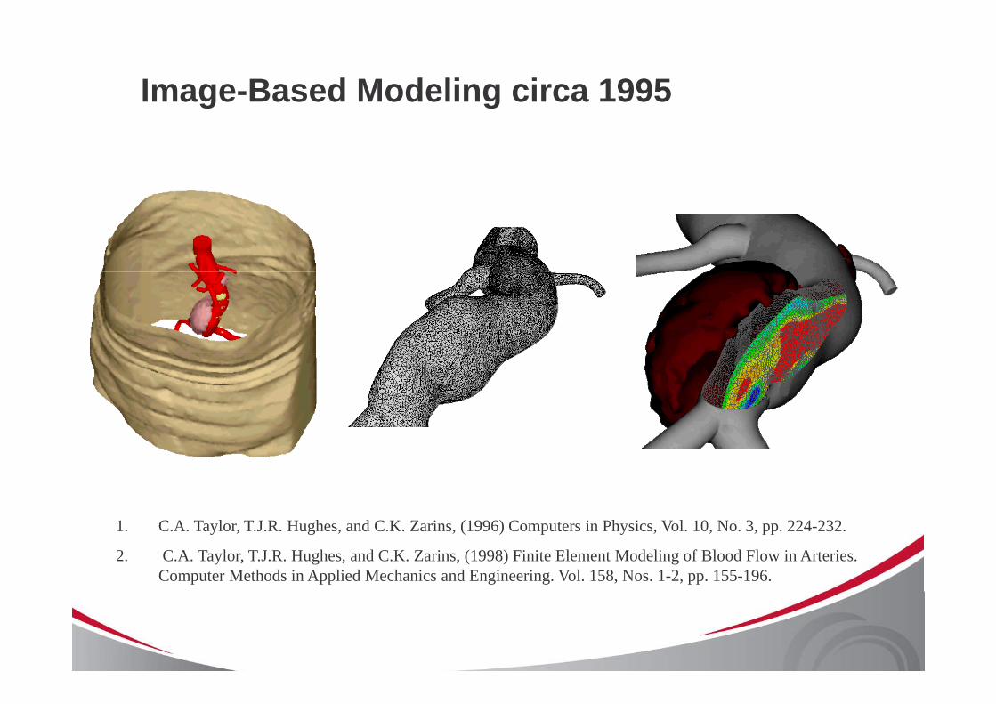
Image-Based Modeling circa 1995
AAA model constructed from Spiral CT data.
Velocity magnitude contours.
Spiral CT data. 1. C.A. Taylor, T.J.R. Hughes, and C.K. Zarins, (1996) Computers in Physics, Vol. 10, No. 3, pp. 224-232.
2. C.A. Taylor, T.J.R. Hughes, and C.K. Zarins, (1998) Finite Element Modeling of Blood Flow in Arteries. Computer Methods in Applied Mechanics and Engineering. Vol. 158, Nos. 1-2, pp. 155-196.
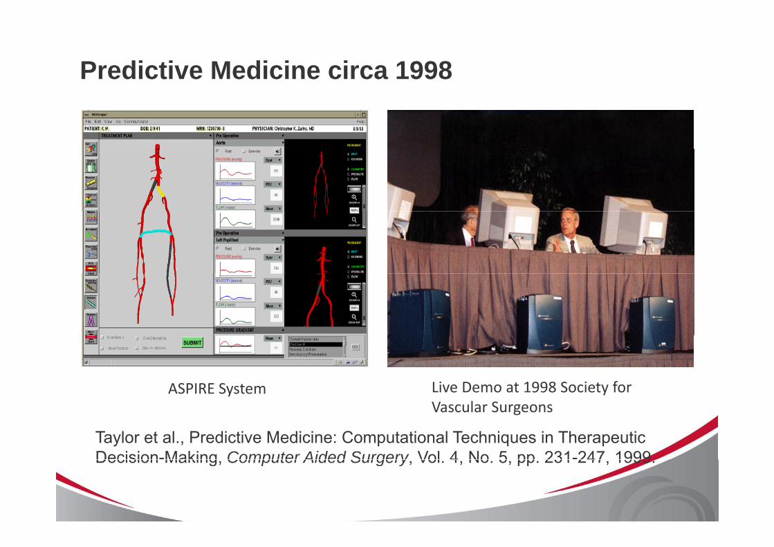
Predictive Medicine circa 1998
ASPIRE System Live Demo at 1998 Society for
Taylor et al., Predictive Medicine: Computational Techniques in Therapeutic Decision-Making Computer Aided Surgery Vol 4 No 5 pp 231-247 1999
Vascular Surgeons
Decision Making, Computer Aided Surgery, Vol. 4, No. 5, pp. 231 247, 1999.
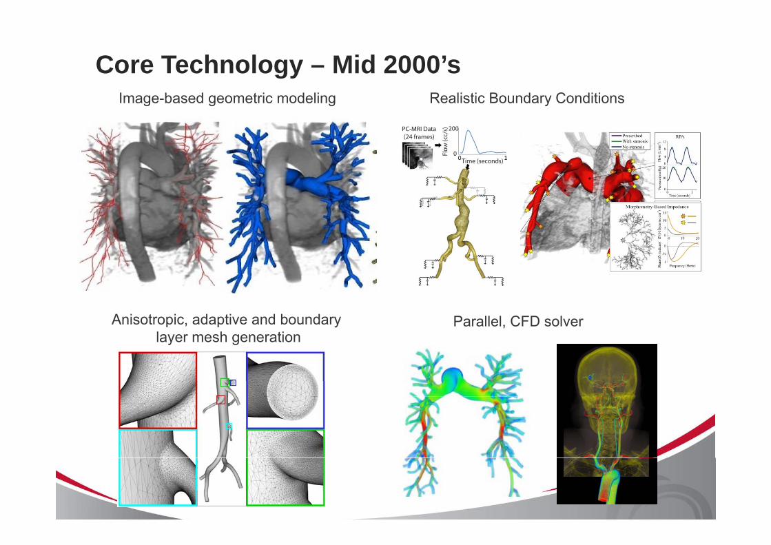
Core Technology – Mid 2000’sImage-based geometric modeling Realistic Boundary Conditions
Anisotropic, adaptive and boundary layer mesh generation
Parallel, CFD solverlayer mesh generation
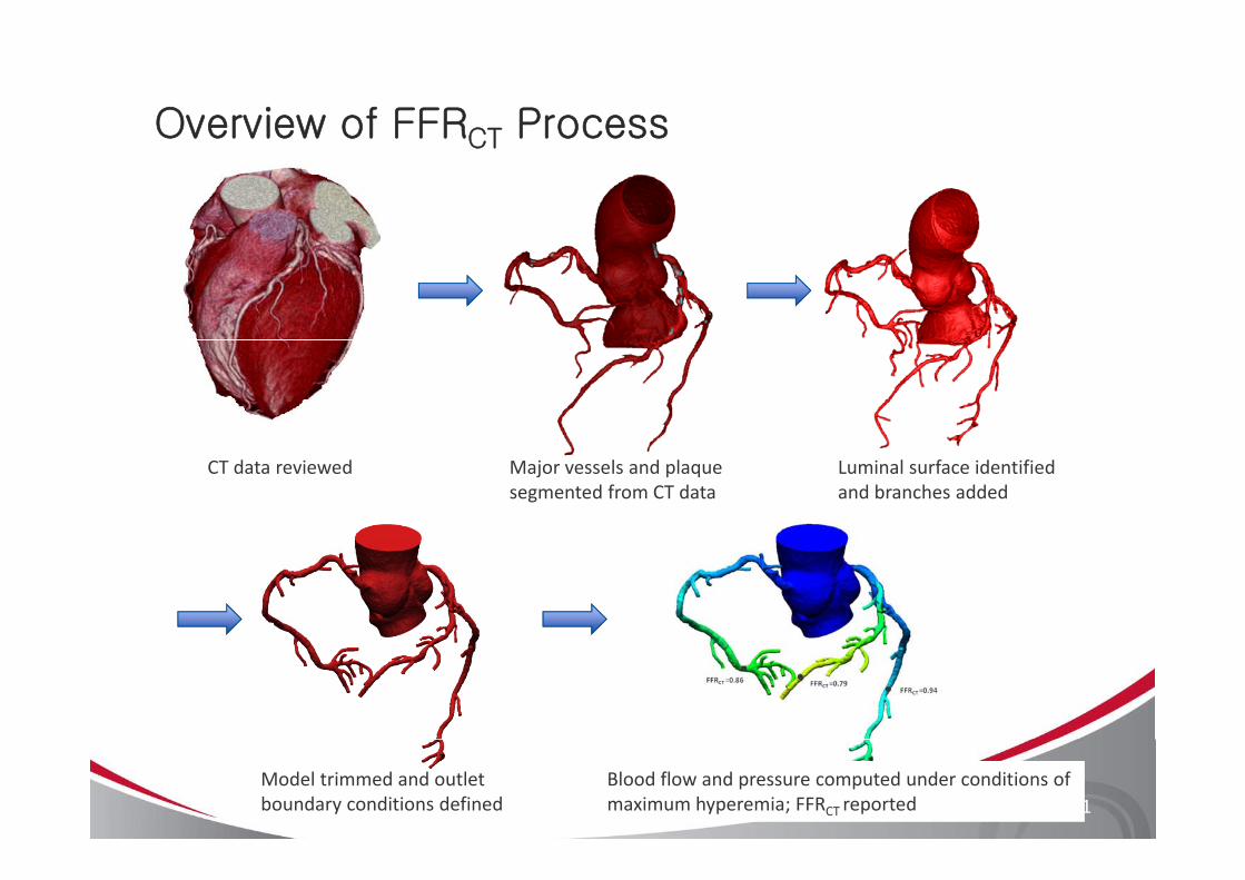
Overview of FFRCT ProcessCT
CT data reviewed Major vessels and plaque segmented from CT data
Luminal surface identified and branches added
Model trimmed and outlet boundary conditions defined
Blood flow and pressure computed under conditions of maximum hyperemia; FFRCT reported 21
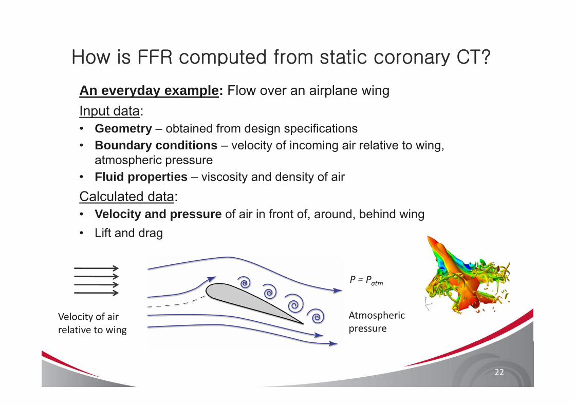
How is FFR computed from static coronary CT?p y
An everyday example: Flow over an airplane wingInput data:Input data:• Geometry – obtained from design specifications• Boundary conditions – velocity of incoming air relative to wing,
t h iatmospheric pressure• Fluid properties – viscosity and density of airCalculated data:• Velocity and pressure of air in front of, around, behind wing • Lift and drag
P = Patm
Velocity of air relative to wing
Atmospheric pressure
22
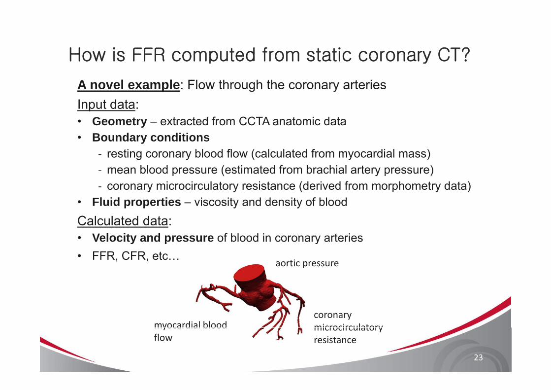
How is FFR computed from static coronary CT?p y
A novel example: Flow through the coronary arteriesInput data:Input data:• Geometry – extracted from CCTA anatomic data• Boundary conditions
ti bl d fl ( l l t d f di l )‐ resting coronary blood flow (calculated from myocardial mass)‐ mean blood pressure (estimated from brachial artery pressure)‐ coronary microcirculatory resistance (derived from morphometry data)
• Fluid properties – viscosity and density of bloodCalculated data:• Velocity and pressure of blood in coronary arteriesVelocity and pressure of blood in coronary arteries • FFR, CFR, etc…
aortic pressure
coronary microcirculatorymyocardial blood microcirculatory resistance
myocardial blood flow
23
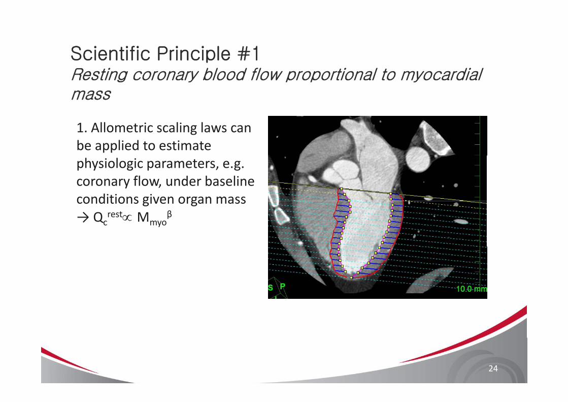
Scientific Principle #1Resting coronary blood flow proportional to myocardial mass
1. Allometric scaling laws can be applied to estimate physiologic parameters, e.g. coronary flow, under baseline conditions given organ massconditions given organ mass → Qc
rest∝ Mmyoβ
24
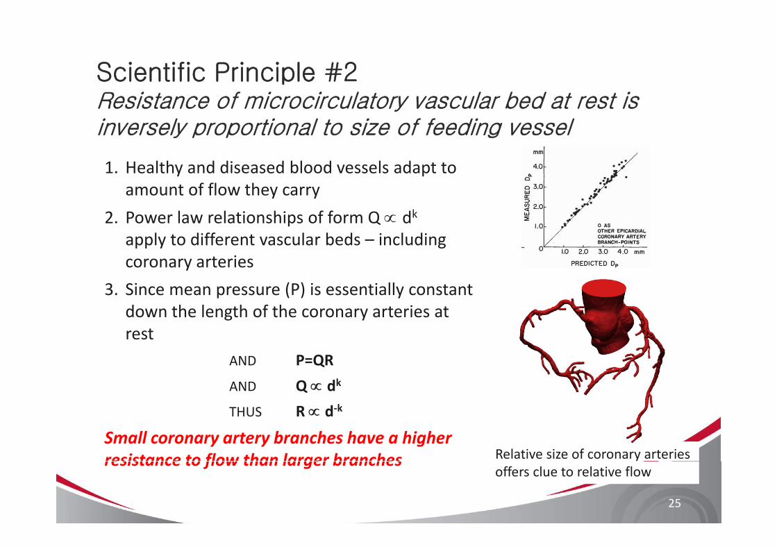
Scientific Principle #2Resistance of microcirculatory vascular bed at rest is inversely proportional to size of feeding vessel
1. Healthy and diseased blood vessels adapt to amount of flow they carry
2 P l l i hi f f Q dk2. Power law relationships of form Q ∝ dkapply to different vascular beds – including coronary arteries
3. Since mean pressure (P) is essentially constant down the length of the coronary arteries at restrest
AND P=QR
AND Q ∝ dk
THUS R ∝ d‐k
Small coronary artery branches have a higher resistance to flow than larger branches Relative size of coronary arteries
25
resistance to flow than larger branchesoffers clue to relative flow
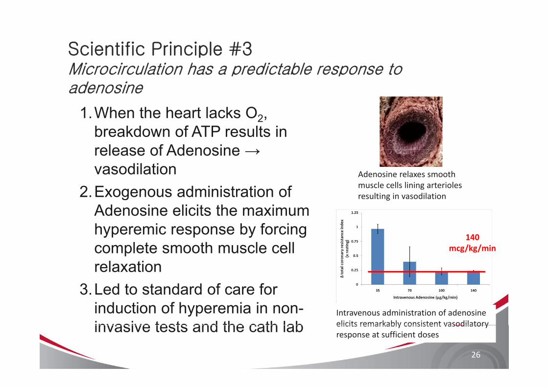
Scientific Principle #3Microcirculation has a predictable response to adenosine
1.When the heart lacks O2, breakdown of ATP results in release of Adenosine →release of Adenosine → vasodilation
2 Exogenous administration ofAdenosine relaxes smooth muscle cells lining arterioles
l i i dil i2.Exogenous administration of Adenosine elicits the maximum hyperemic response by forcing
resulting in vasodilation
140yp p y g
complete smooth muscle cell relaxation
140mcg/kg/min
3.Led to standard of care for induction of hyperemia in non-invasive tests and the cath lab
Intravenous administration of adenosine elicits remarkably consistent vasodilatory
26
invasive tests and the cath lab elicits remarkably consistent vasodilatoryresponse at sufficient doses

HeartFlow Process for Obtaining FFRCTg CT
Computational Model based on coronary CTA
Blood Flow Solution
Calculate FFRCT
3-D quantitative, anatomic model from coronary CTA
Blood flow equations solved on supercomputer
3D FFRCT map computed
based on coronary CTA Solution
Physiologic models:
-Myocardial demandMorphometry based FFR 0 72-Morphometry-based boundary conditions
-Effect of adenosine on microcirculation
FFRCT = 0.72(can select any point on model)
27
microcirculation
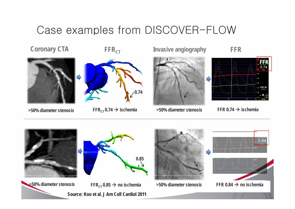
Case examples from DISCOVER-FLOW
Coronary CTA Invasive angiographyFFRCT FFR
Case examples from DISCOVER FLOW
FFR
0.74
>50% diameter stenosis >50% diameter stenosisFFRCT 0.74 ischemia FFR 0.74 ischemia
FFR
0.85
>50% diameter stenosis FFRCT 0.85 no ischemia FFR 0.84 no ischemia>50% diameter stenosis
Source: Koo et al. J Am Coll Cardiol 2011
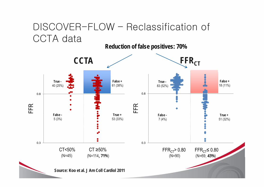
DISCOVER-FLOW – Reclassification of
Reduction of false positives: 70%
DISCOVER FLOW Reclassification of CCTA data
CCTA FFRCT
0 8 0 8
False +61 (38%)
False +18 (11%)
True -40 (25%)
True -83 (52%)
0.8
FFR
0.8
FFR
True +False True +False True +53 (33%)
False -5 (3%)
True +51 (32%)
False -7 (4%)
0.3
CT<50% CT ≥50%0.3
FFRCT> 0.80 FFRCT≤ 0.80 (N=69, 43%)(N=90)(N=114, 71%)(N=45) (N 69, 43%)(N 90)(N 114, 71%)( 5)
Source: Koo et al. J Am Coll Cardiol 2011 29
Frequently Asked Questionsq y
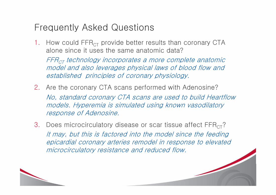
1. How could FFRCT provide better results than coronary CTA alone since it uses the same anatomic data?
FFRCT technology incorporates a more complete anatomic model and also leverages physical laws of blood flow and established principles of coronary physiologyestablished principles of coronary physiology.
2. Are the coronary CTA scans performed with Adenosine?
No standard coronary CTA scans are used to build HeartflowNo, standard coronary CTA scans are used to build Heartflowmodels. Hyperemia is simulated using known vasodilatoryresponse of Adenosine.
3. Does microcirculatory disease or scar tissue affect FFRCT?
It may, but this is factored into the model since the feeding epicardial coronary arteries remodel in response to elevatedepicardial coronary arteries remodel in response to elevated microcirculatory resistance and reduced flow.
Frequently Asked Questionsq y
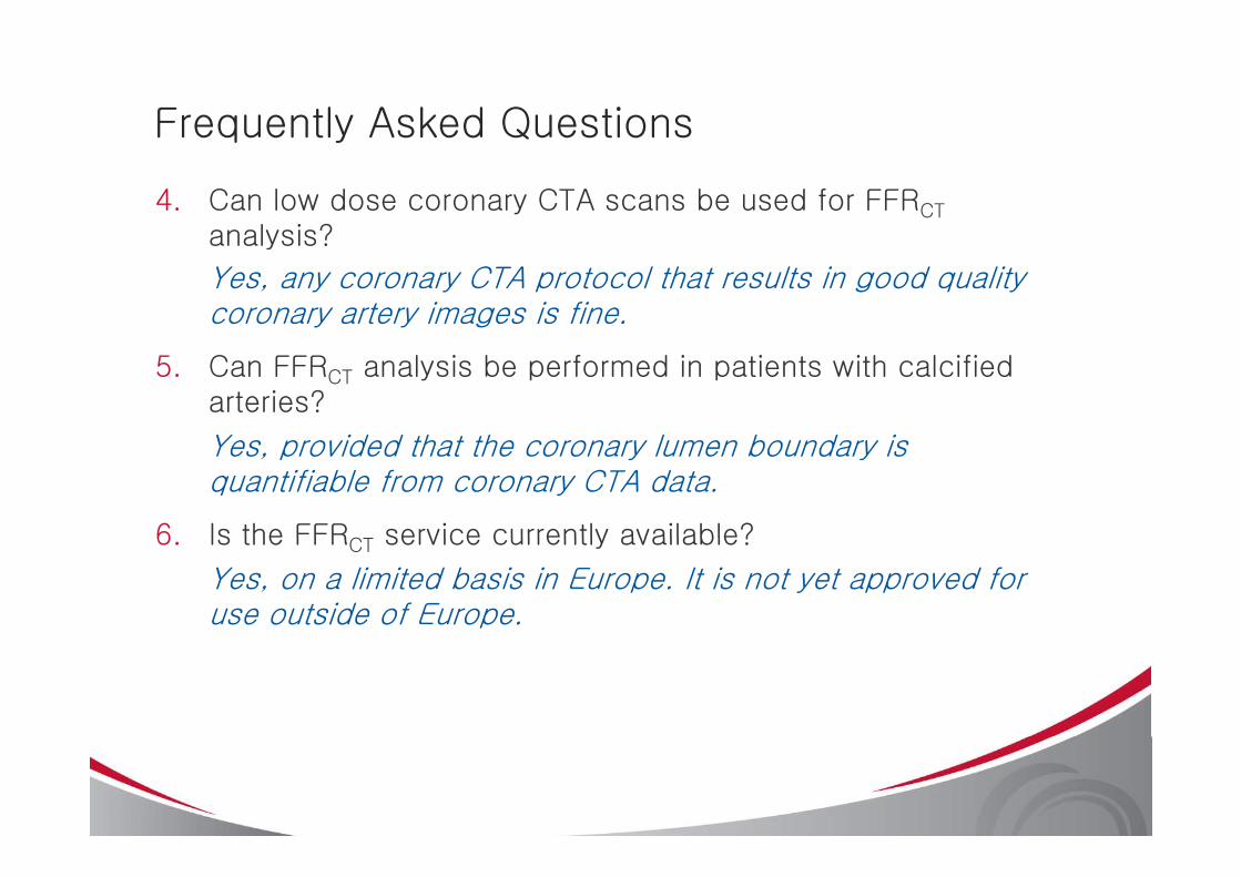
4. Can low dose coronary CTA scans be used for FFRCT
analysis?analysis?
Yes, any coronary CTA protocol that results in good quality coronary artery images is fine.
5. Can FFRCT analysis be performed in patients with calcified arteries?
Y id d th t th l b d iYes, provided that the coronary lumen boundary is quantifiable from coronary CTA data.
6 Is the FFRCT service currently available?6. Is the FFRCT service currently available?
Yes, on a limited basis in Europe. It is not yet approved for use outside of Europe.
SummarySummary
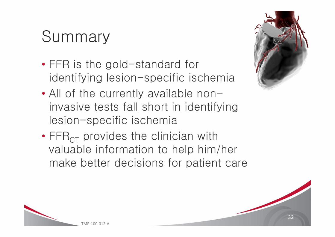
• FFR is the gold-standard for• FFR is the gold standard for identifying lesion-specific ischemia
All of the currently available non• All of the currently available non-invasive tests fall short in identifying lesion specific ischemialesion-specific ischemia
• FFRCT provides the clinician with l bl i f i h l hi /hvaluable information to help him/her
make better decisions for patient care
32TMP‐100‐012‐A