Embed Size (px)
Citation preview

Oct. 29, 2009
Kim, Han Gon
1
Development of Passive Aux. Feedwater System in ALWR in Korea
CONTEN TS
Ⅱ. Design of PAFSⅡ. Design of PAFS
Ⅰ. IntroductionⅠ. Introduction
Ⅲ. Preliminary AnalysisⅢ. Preliminary Analysis
Ⅳ. Separate Effect TestsⅣ. Separate Effect Tests
Ⅴ. Integral Effect TestsⅤ. Integral Effect Tests
Ⅵ. Future PlanⅥ. Future Plan
Introduction
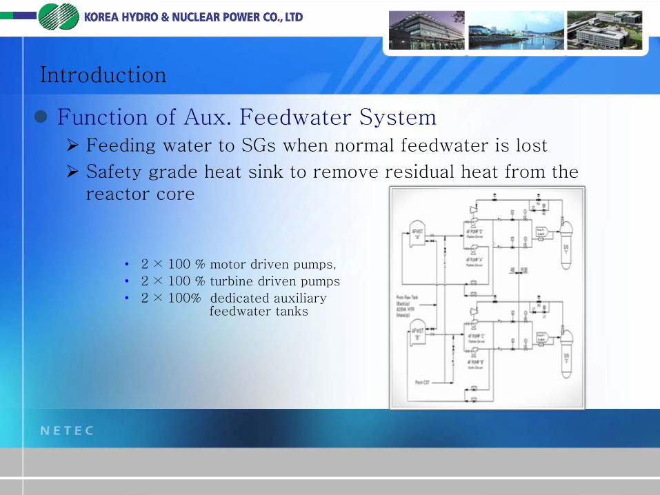
Function of Aux. Feedwater System
Feeding water to SGs when normal feedwater is lost
Safety grade heat sink to remove residual heat from the reactor core
•
2 ×
100 % motor driven pumps,
•
2 ×
100 % turbine driven pumps
•
2 ×
100% dedicated auxiliary feedwater tanks
Introduction
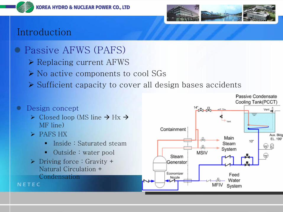
Passive AFWS (PAFS)
Replacing current AFWS
No active components to cool SGs
Sufficient capacity to cover all design bases accidents
Design concept
Closed loop (MS line
Hx
MF line)
PAFS HX
Inside : Saturated steam
Outside : water pool
Driving force : Gravity + Natural Circulation + Condensation
Introduction
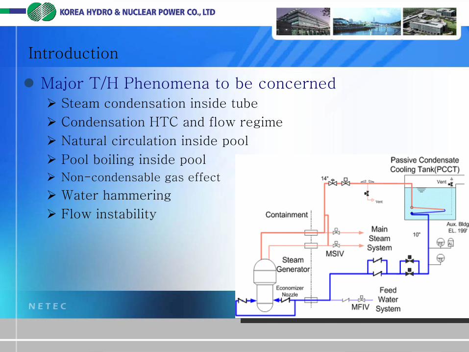
Major T/H Phenomena to be concerned
Steam condensation inside tube
Condensation HTC and flow regime
Natural circulation inside pool
Pool boiling inside pool
Non-condensable gas effect
Water hammering
Flow instability
Design of PAFS
Design Requirements
It has to remove the residual heat of core in case of DBA postulated SGs’
cool-down
The capacity of PAFS covers at least 8 hours hot shutdown operation without any operator action in case of SBO in order to prevent the core damage
All the power source is to be eliminated except the Class 1E DC

Design of PAFS
Design of Heat Exchanger
4 bundles consist of horizontally 62 U-tubes
Tube
ID : 44.8mm
OD : 50.8mm
Inclined angle: 3 °
Tube pitch : 114mm (Min.)
Header Diameter : 30”
Design of PAFS
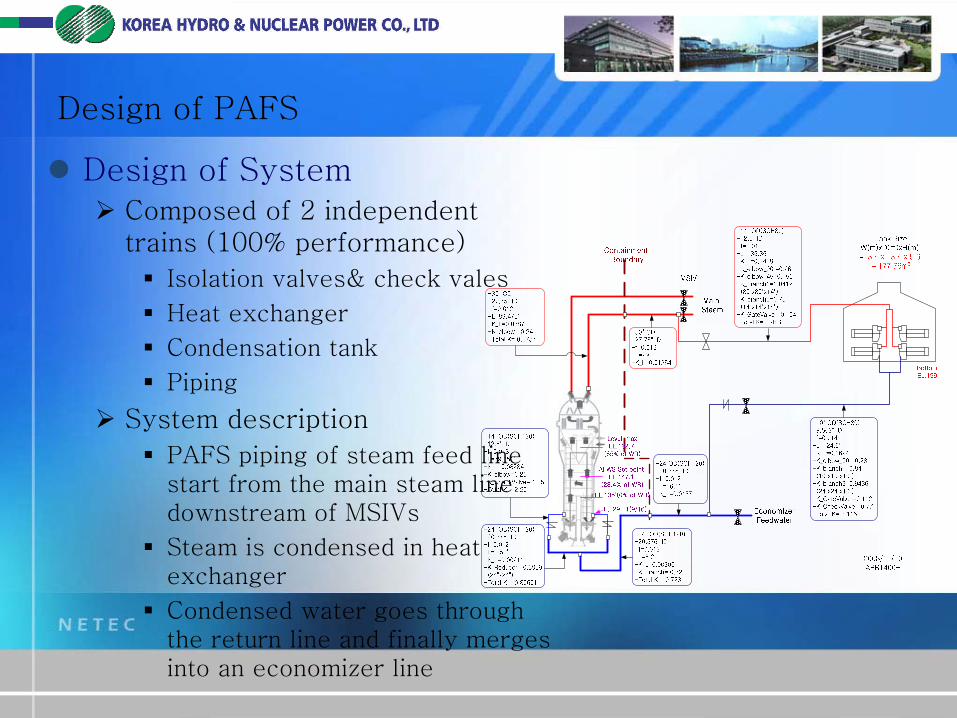
Design of System
Composed of 2 independent trains (100% performance)
Isolation valves& check vales
Heat exchanger
Condensation tank
Piping
System description
PAFS piping of steam feed line start from the main steam line downstream of MSIVs
Steam is condensed in heat exchanger
Condensed water goes through the return line and finally merges into an economizer line
Preliminary Performance Analysis
Purposes
To make initial sizing of HXs and system configuration
To get intuition for experiments
Tools
Best-estimate T/H code (MARS and RELAP5/Mod3.3]
Event
Loss of main feedwater accident for APR1400
Assumption
No operator action during an accident
Single failure : one PAFS valve open fail
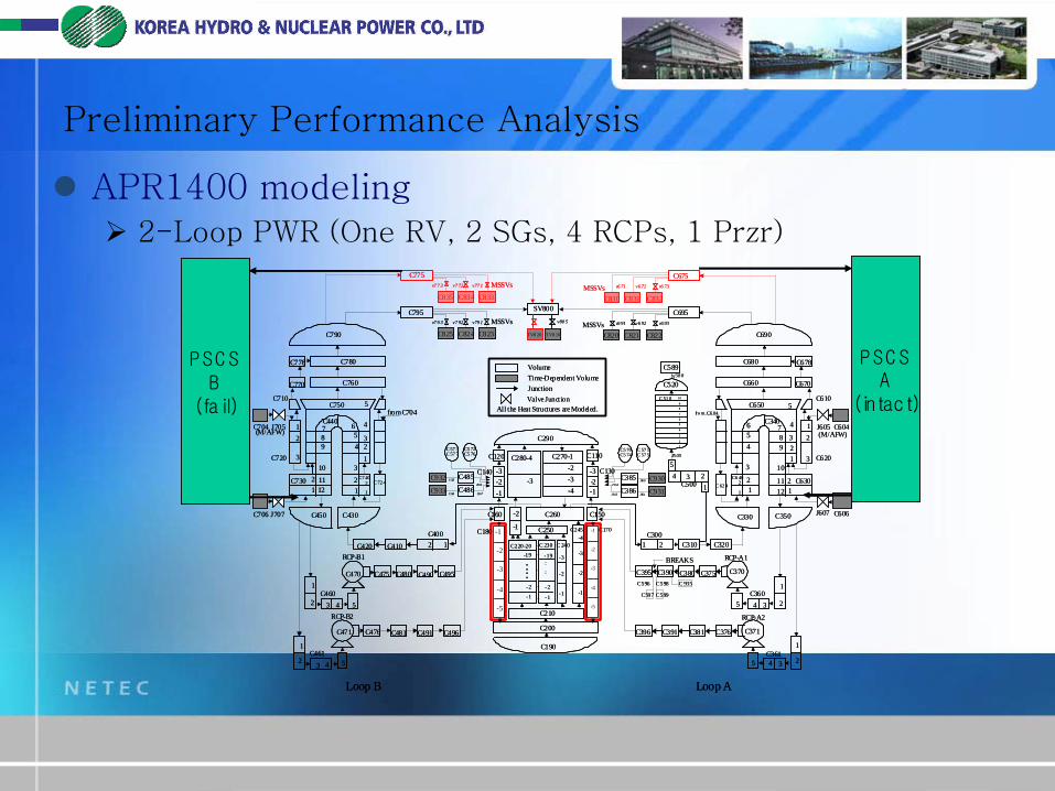
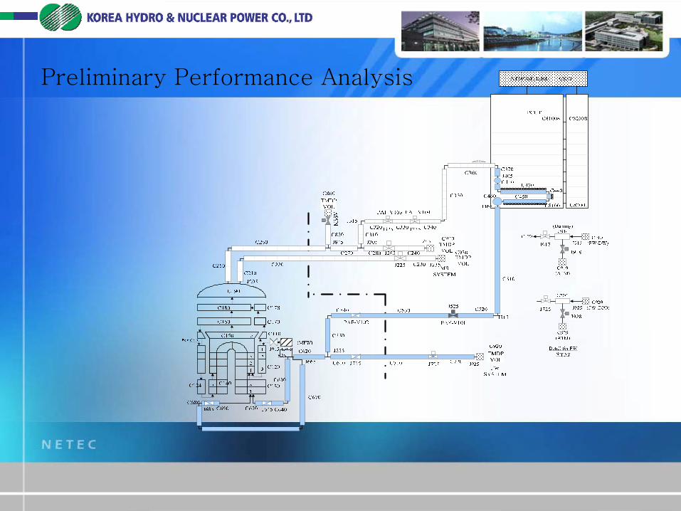
Preliminary Performance Analysis
APR1400 modeling
2-Loop PWR (One RV, 2 SGs, 4 RCPs, 1 Przr)
C790
C778 C780
C770 C760
C704
C706
C710
J705
J707
C720
12
3
C750 5
4
32
1
C440
12
3
45
6789
10
1112
from C704
C73012 C 72 4
C7 40
1
2
C450 C430
C4611
2
C4601
2 3 4 5
RCP-B1
C470 C475 C480 C490 C495
C420 C410
C40012
3 4 5
RCP-B2
C471 C476 C481 C491 C496
C695
C690
C680
C660
C678
C670
C610C650
123
4
5
C340
12
3
456 7
89
10
1112
fro m C6 04
C604
C606
J605
J607
C620
12
3
21
C630
C330 C350
C 62 41
2C6 40
C500 1234
5
C3611
2345
RCP-A2
C371C376C381C391C396
C3601
2345
RCP-A1
C370C375C380C390C395
C3001 2 C310 C320
Loop B Loop A
C820 C821
MSSVs MSSVs
BREAKS
C596 C598
C597 C599
(M/AFW) (M/AFW)
C822
C 935
C520
C 51 0
12
3
4
567
89
10
J5 05
C589
J562C932 C485
J563C933 C486
C5 76C 57 3 C5 72C 57 7
J566
J567
J560 C930C385
J561 C931C386
C5 74C 57 1C5 70C 57 5
J564
J565
VolumeTime-Dependent Volume
Valve JunctionJunction
All the Heat Structures are Modeled.
sj58 8
v6 91 v6 92 v6 93v79 1v7 92v7 9 3
C170-1
-2
-3
-4
C190
C200
C210
160C C150
-1
-2
-3
C245
C220-20-19
-1
-2
C 230
-19
-2
-1
::
::
C250
C260
C270-1-2-3
C280-4
C290
C140 -3-2-1
C110
C130-3-2-1-4
-3
-4
-5
-1
-2
-3
-4
-5
C180
-2
-1
C120
-3
-2
-1
C 240
C825 C823C824
SV800
v80 5
C795
TV8 10TV8 20
MSSVsv77 1v7 72v7 7 3
C835 C834
C775
C833
C675
C830 C831MSSVs
C832
v6 71 v6 72 v6 73
P SC SA
(intact)
P SC SB(fail)
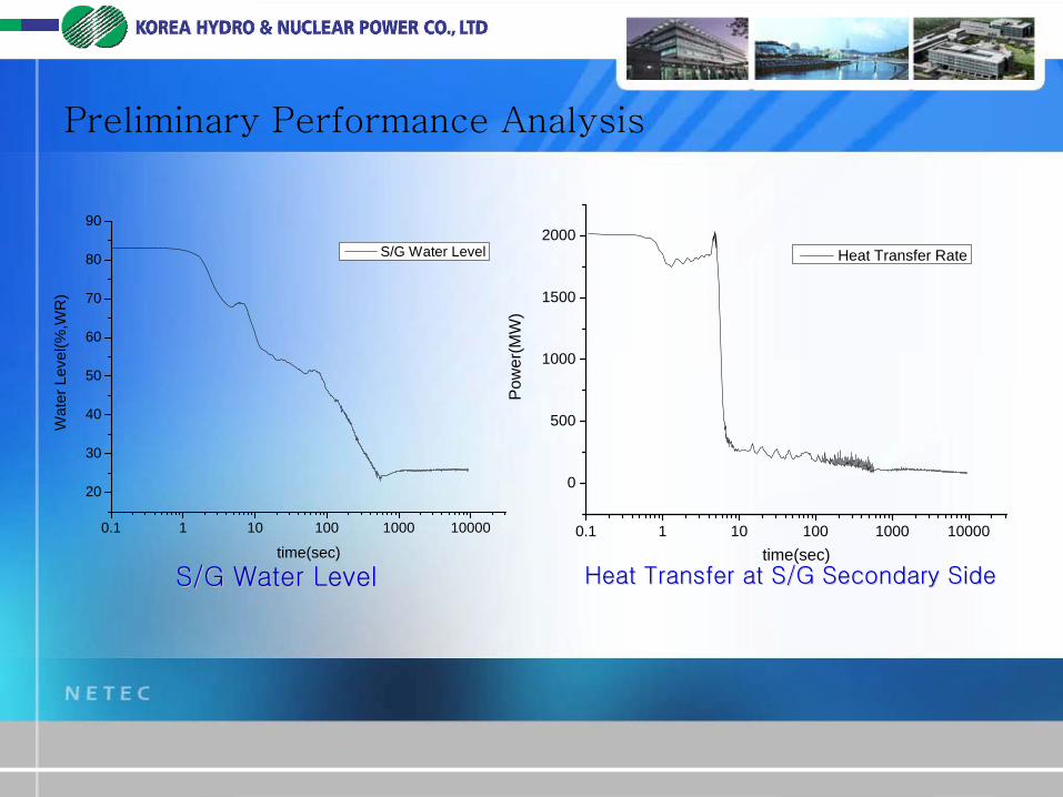
Preliminary Performance Analysis
Preliminary Performance Analysis
S/G Water LevelS/G Water Level Heat Transfer at S/G Secondary SideHeat Transfer at S/G Secondary Side
0.1 1 10 100 1000 10000
20
30
40
50
60
70
80
90
Wat
er L
evel
(%,W
R)
time(sec)
S/G Water Level
0.1 1 10 100 1000 10000
0
500
1000
1500
2000
Pow
er(M
W)
time(sec)
Heat Transfer Rate
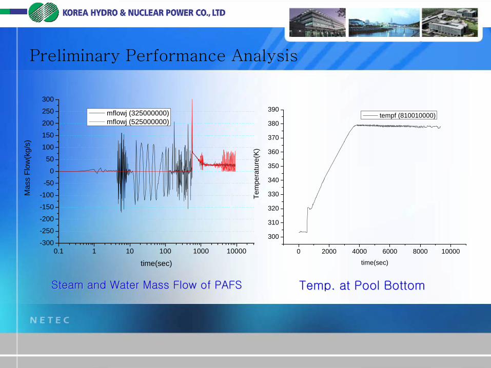
Preliminary Performance Analysis
Steam and Water Mass Flow of PAFSSteam and Water Mass Flow of PAFS
0.1 1 10 100 1000 10000-300
-250
-200
-150
-100
-50
0
50
100
150
200
250
300
Mas
s Fl
ow(k
g/s)
time(sec)
mflowj (325000000) mflowj (525000000)
Temp. at Pool BottomTemp. at Pool Bottom
0 2000 4000 6000 8000 10000
300
310
320
330
340
350
360
370
380
390
Tem
pera
ture
(K)
time(sec)
tempf (810010000)
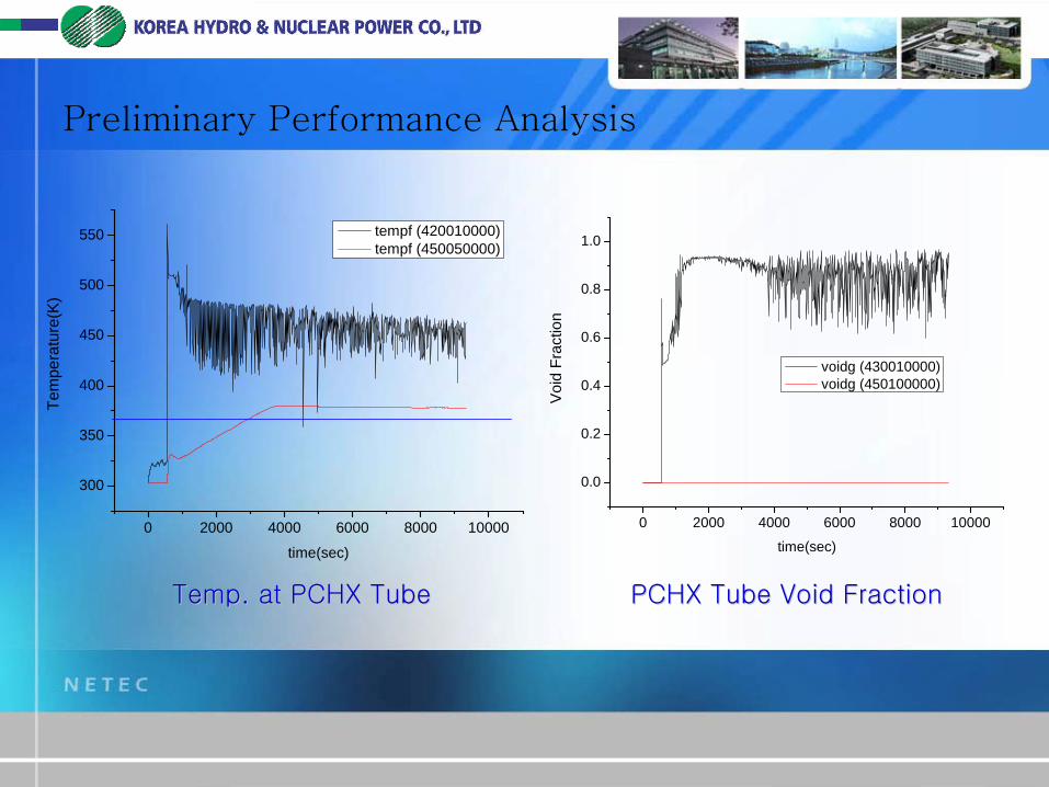
Preliminary Performance Analysis
Temp. at PCHX TubeTemp. at PCHX Tube
0 2000 4000 6000 8000 10000
300
350
400
450
500
550
Tem
pera
ture
(K)
time(sec)
tempf (420010000) tempf (450050000)
PCHX Tube Void FractionPCHX Tube Void Fraction
0 2000 4000 6000 8000 10000
0.0
0.2
0.4
0.6
0.8
1.0
Voi
d Fr
actio
ntime(sec)
voidg (430010000) voidg (450100000)
Separate Effect Tests (SET)
Purposes
To measure condensation HTC
To identify flow regime along the tube
To identify non-condensable gas effect
To measure natural circulation capability in the pool
To measure flow instability
Characteristics of the facility
Scaling : 1/124 volume scale (full height)
Water pool : conserve geometric shape
HX tubes : 1/1 area and length, 1/124 # of tubes

Separate Effect Tests
Test facility
Steam Generator (SG)
100 bar, 1.5MW Heat Generation
PAFS Tank
Full height, reduced area
SG Pressure Control Sys.
Exhausted Steam Dump Sys
PAFS Tank Filling and Heating Sys.
Initial De-gassing Sys.

Separate Effect Tests
Measurement system
PAFS Tank
130 Thermo-couples to measure natural circulation
130 void fraction sensors and visual windows
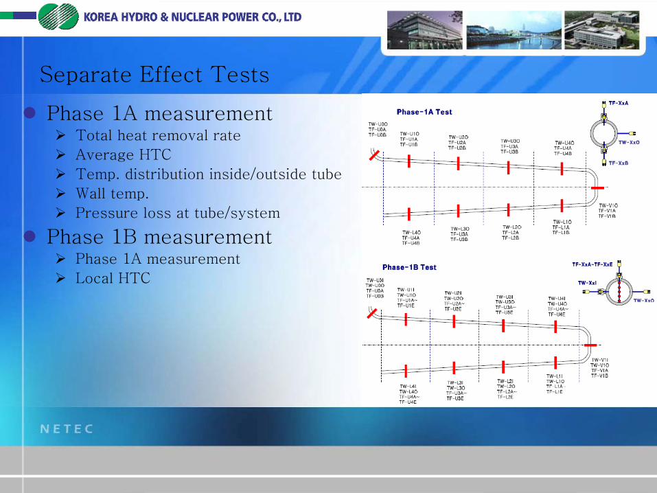
Separate Effect Tests
Phase 1A measurement
Total heat removal rate
Average HTC
Temp. distribution inside/outside tube
Wall temp.
Pressure loss at tube/system
Phase 1B measurement
Phase 1A measurement
Local HTC

Separate Effect Tests
Phase 2 measurement
Flow regime
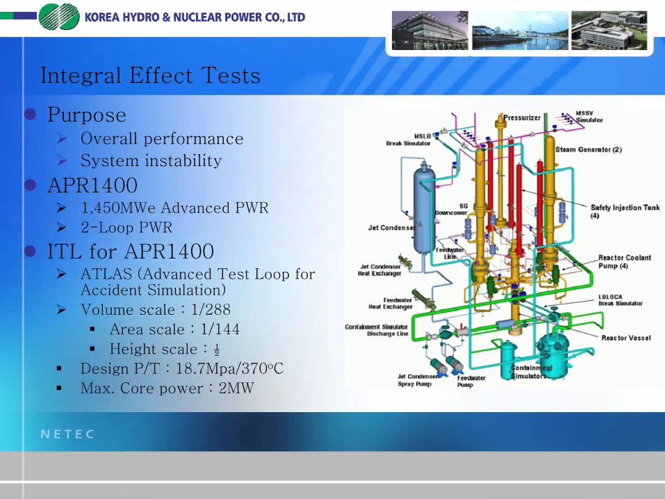
Integral Effect Tests
Purpose
Overall performance
System instability
APR1400
1,450MWe Advanced PWR
2-Loop PWR
ITL for APR1400
ATLAS (Advanced Test Loop for Accident Simulation)
Volume scale : 1/288
Area scale : 1/144
Height scale : ½
Design P/T : 18.7Mpa/370oC
Max. Core power : 2MW

Integral Effect Tests
IET using ATLAS
PAFS at one SG
Height scale : ½
Water pool : ATLAS scale
Steam line : pressure drop scale
Water line : pressure drop and volume scale
HXs
Conserve condensation HTC and flow regime
Local scaling

Current Status and Future Plan
‘07 ‘08 ‘09 ‘10 ‘11 ‘12
DesignBasic Design
Detail Design
Analysis
Preliminary analysis
Safety analysis
TestSET
IET
Current