Embed Size (px)
Citation preview
Development of the magnet
power supplies at
The Australian Synchrotron
Sean Murphy
POCPA - 2012
Introduction
• Upgrading storage ring magnet power supplies to Danfysik 9100 series modules
• Upgrade of the dipole power supply controller
• Shielding of the dipole cables
• Development of pulsed power supplies for top-up operation
Introduction
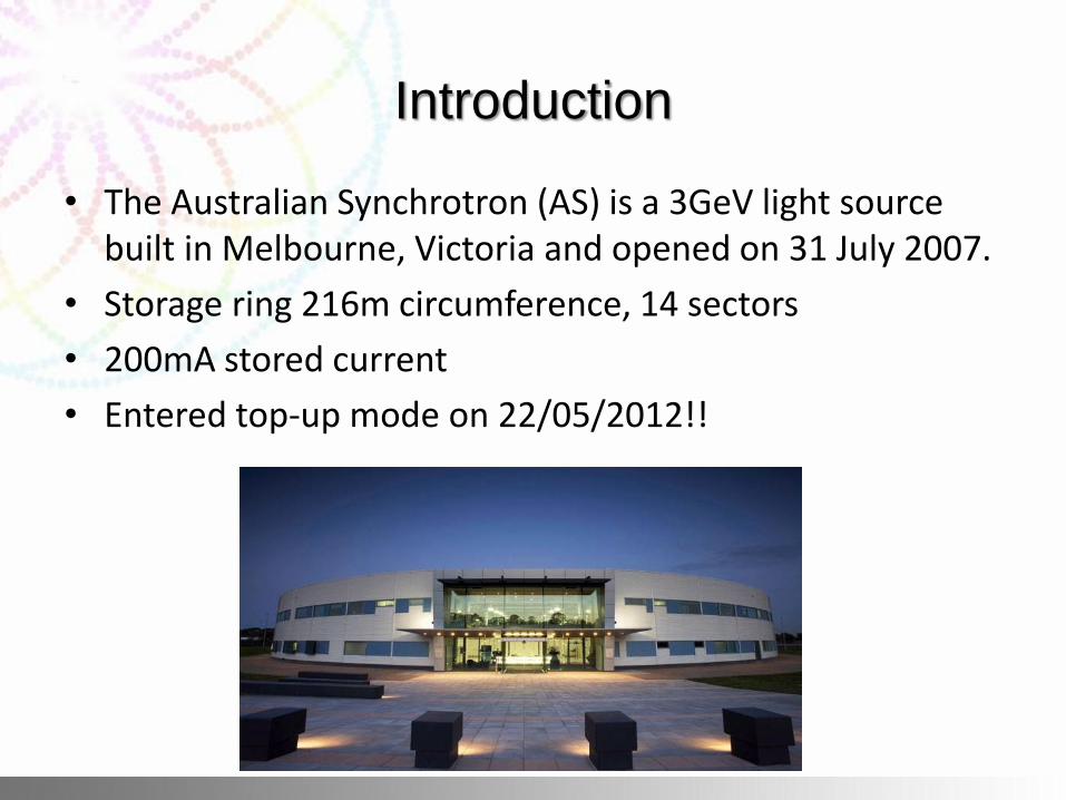
• The Australian Synchrotron (AS) is a 3GeV light source built in Melbourne, Victoria and opened on 31 July 2007.
• Storage ring 216m circumference, 14 sectors
• 200mA stored current
• Entered top-up mode on 22/05/2012!!
SR Magnet Power Supply Upgrade
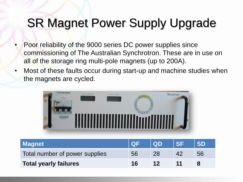
• Poor reliability of the 9000 series DC power supplies since
commissioning of The Australian Synchrotron. These are in use on
all of the storage ring multi-pole magnets (up to 200A).
• Most of these faults occur during start-up and machine studies when
the magnets are cycled.
Magnet QF QD SF SD
Total number of power supplies 56 28 42 56
Total yearly failures 16 12 11 8
SR Magnet Power Supply Upgrade
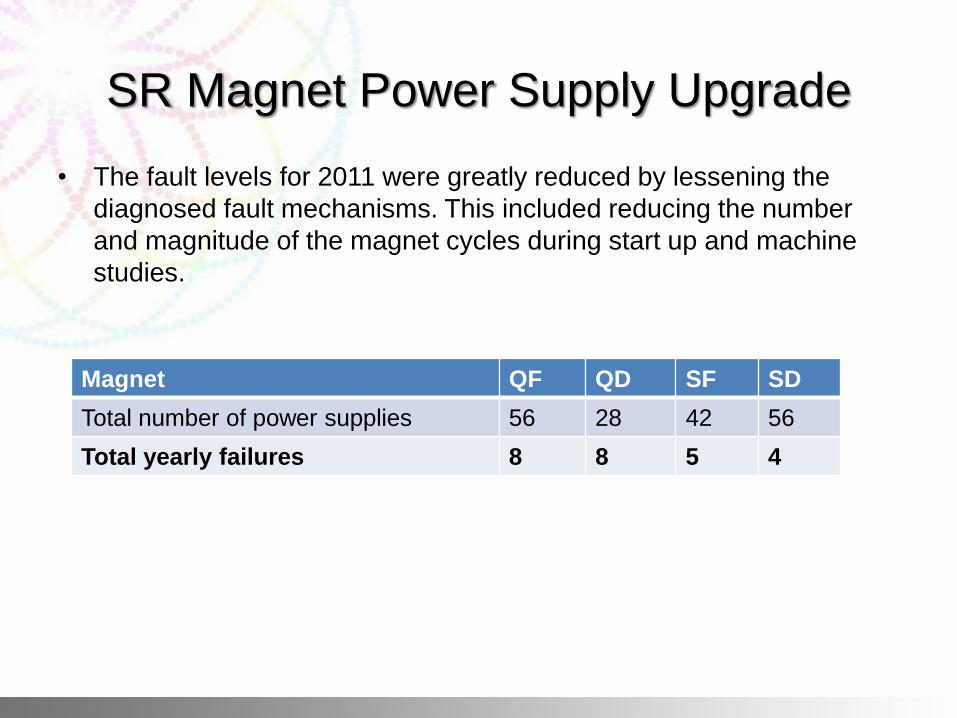
• The fault levels for 2011 were greatly reduced by lessening the
diagnosed fault mechanisms. This included reducing the number
and magnitude of the magnet cycles during start up and machine
studies.
Magnet QF QD SF SD
Total number of power supplies 56 28 42 56
Total yearly failures 8 8 5 4
SR Magnet Power Supply Upgrade
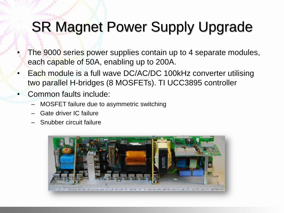
• The 9000 series power supplies contain up to 4 separate modules,
each capable of 50A, enabling up to 200A.
• Each module is a full wave DC/AC/DC 100kHz converter utilising
two parallel H-bridges (8 MOSFETs). TI UCC3895 controller
• Common faults include:
– MOSFET failure due to asymmetric switching
– Gate driver IC failure
– Snubber circuit failure
SR Magnet Power Supply Upgrade
• Improved reliability of the newer 9100 series Danfysik power supply
was proven after extensive testing.
• The 9100 series modules include key design changes including:
– Galvanic isolation using gate drive transformers
– Separate ground for control electronics
– Relocated control circuit and rerouted PCB, shortened signal paths
– Heavy duty snubber circuit
SR Magnet Power Supply Upgrade
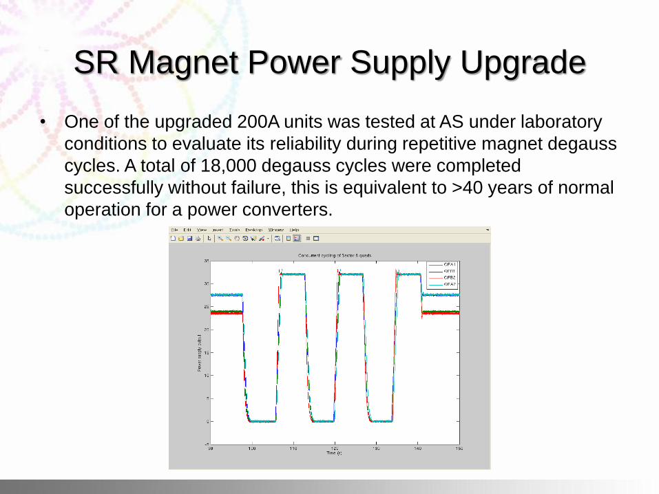
• One of the upgraded 200A units was tested at AS under laboratory
conditions to evaluate its reliability during repetitive magnet degauss
cycles. A total of 18,000 degauss cycles were completed
successfully without failure, this is equivalent to >40 years of normal
operation for a power converters.
SR Magnet Power Supply Upgrade
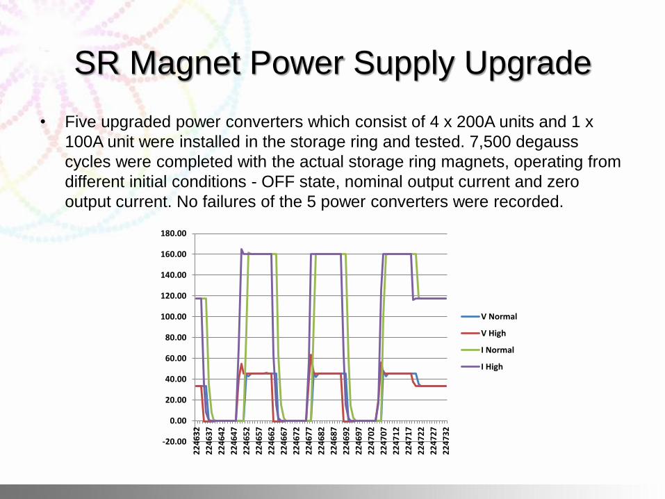
• A typical magnet cycle program would be:
• The power supply goes to 160A for 5 seconds.
• The power supply starts at 0A for 5 seconds.
• The power supply goes to 160A for 5 seconds.
• The power supply starts at 0A for 5 seconds.
• The power supply goes to 160A for 5 seconds.
• The power supply goes to 118A for 30 seconds and repeats.
SR Magnet Power Supply Upgrade
• Five upgraded power converters which consist of 4 x 200A units and 1 x
100A unit were installed in the storage ring and tested. 7,500 degauss
cycles were completed with the actual storage ring magnets, operating from
different initial conditions - OFF state, nominal output current and zero
output current. No failures of the 5 power converters were recorded.
-20.00
0.00
20.00
40.00
60.00
80.00
100.00
120.00
140.00
160.00
180.00
22
46
32
22
46
37
22
46
42
22
46
47
22
46
52
22
46
57
22
46
62
22
46
67
22
46
72
22
46
77
22
46
82
22
46
87
22
46
92
22
46
97
22
47
02
22
47
07
22
47
12
22
47
17
22
47
22
22
47
27
22
47
32
V Normal
V High
I Normal
I High
SR Magnet Power Supply Upgrade
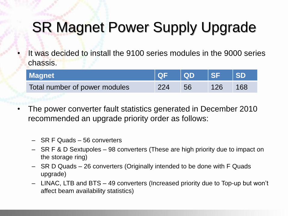
• It was decided to install the 9100 series modules in the 9000 series
chassis.
• The power converter fault statistics generated in December 2010
recommended an upgrade priority order as follows:
– SR F Quads – 56 converters
– SR F & D Sextupoles – 98 converters (These are high priority due to impact on
the storage ring)
– SR D Quads – 26 converters (Originally intended to be done with F Quads
upgrade)
– LINAC, LTB and BTS – 49 converters (Increased priority due to Top-up but won’t
affect beam availability statistics)
Magnet QF QD SF SD
Total number of power modules 224 56 126 168
SR Magnet Power Supply Upgrade
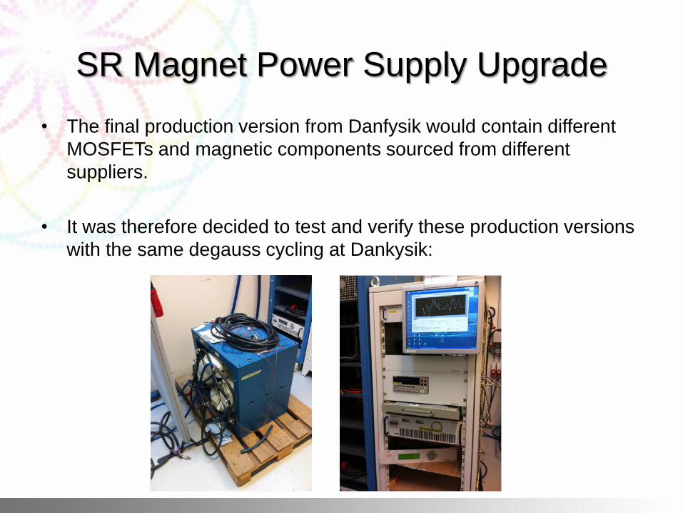
• The final production version from Danfysik would contain different
MOSFETs and magnetic components sourced from different
suppliers.
• It was therefore decided to test and verify these production versions
with the same degauss cycling at Dankysik:
SR Magnet Power Supply Upgrade
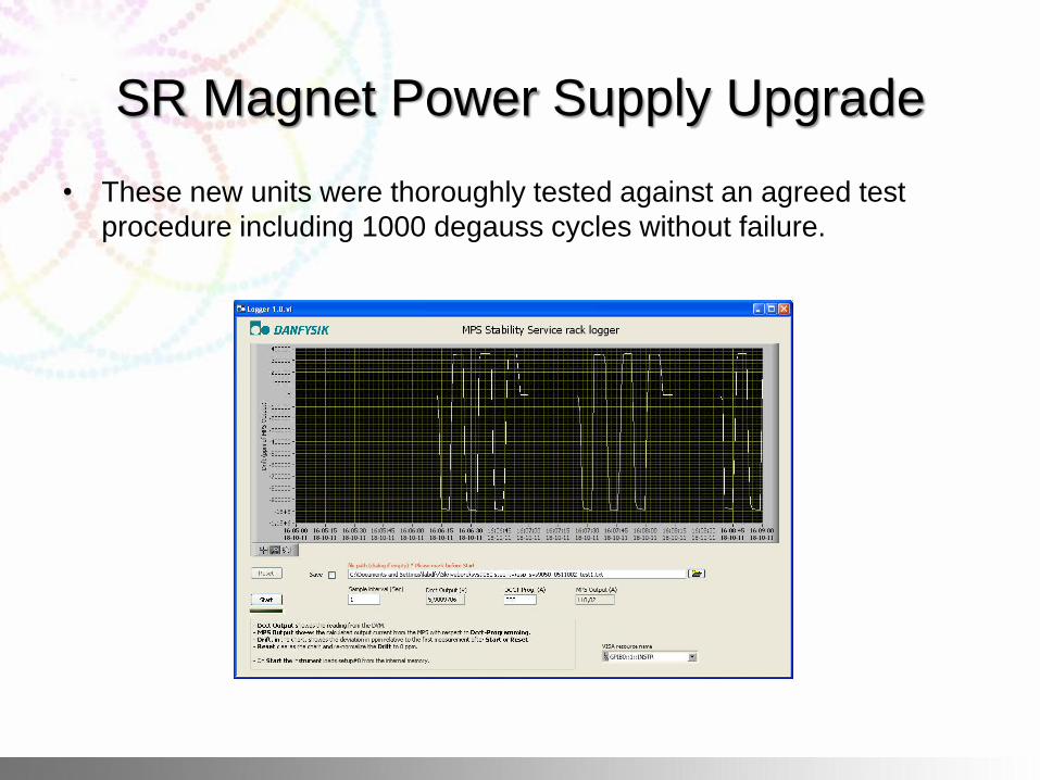
• These new units were thoroughly tested against an agreed test
procedure including 1000 degauss cycles without failure.
SR Magnet Power Supply Upgrade
• All 56 SR Focus Quadrupole power converters were upgraded in
January 2012. Each unit was degauss cycled a minimum of 100
times.
• They have since been operational to present without a failure.
• Phase 2: Sept 2012 – Upgrade approximately 49 Sextupole and 14
D Quadrupole magnet power converters and procure enough power
modules to hold adequate stock of spares.
Dipole Power Supply Shielding
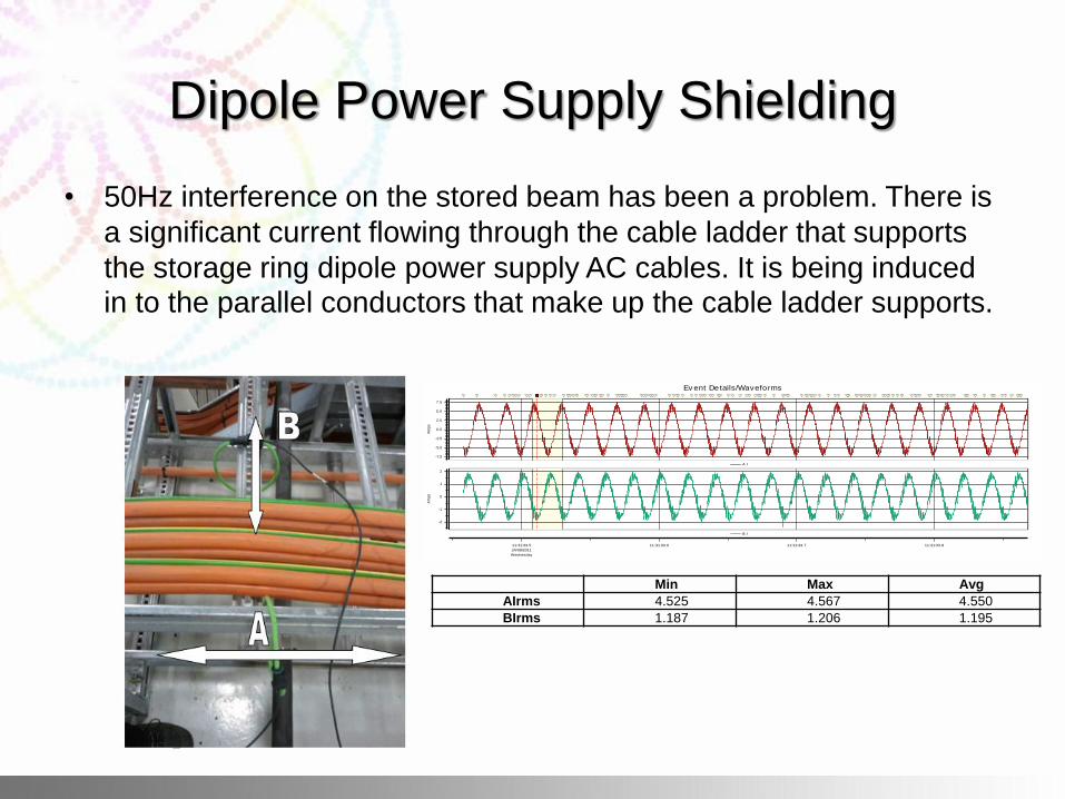
• 50Hz interference on the stored beam has been a problem. There is
a significant current flowing through the cable ladder that supports
the storage ring dipole power supply AC cables. It is being induced in to the parallel conductors that make up the cable ladder supports.
Min Max Avg
AIrms 4.525 4.567 4.550
BIrms 1.187 1.206 1.195
Ev ent Details/Waveforms
11:31:33.5
24/08/2011
Wednesday
11:31:33.6 11:31:33.7 11:31:33.8
-7.5
-5.0
-2.5
0.0
2.5
5.0
7.5
Am
ps
A I
-2
-1
0
1
2
Am
ps
B I
Dipole Power Supply Shielding
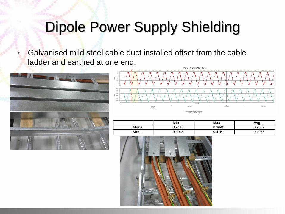
• Galvanised mild steel cable duct installed offset from the cable
ladder and earthed at one end:
Event #21 at 12/10/2011 12:01:24.039
A-BV Severe Arcing Full Cyc
Phase 362.6 Deg
Ev ent Details/Waveforms
12:01:24.1
12/10/2011
Wednesday
12:01:24.2 12:01:24.3 12:01:24.4
-1.5
-1.0
-0.5
0.0
0.5
1.0
1.5
Am
ps
A I
-0.50
-0.25
0.00
0.25
0.50
0.75
Am
ps
B I
Min Max Avg
AIrms 0.9414 0.9640 0.9509
BIrms 0.3945 0.4151 0.4036
Dipole Power Supply Shielding
• Due to the adequate shielding capabilities of the steel conduit, and
the ease with which it can be installed on the dipole power supply
AC cables, it is strongly recommended to fully shield these cables
from the power supply, to the cable gantry. This will reduce the EMF
radiated from these cables and the subsequent induced 50Hz noise
by at least 75%.
• Relocation of the dipole power supply with only the output DC
cables running across the machine to the dipole magnets would
reduce the induced current significantly; the only changing magnetic
field would be due to the ripple on the output current. This would
require a suitable location to be found, and suitable cabling and
plumbing for cooling water to be installed to this new location.
Dipole Power Supply Controller
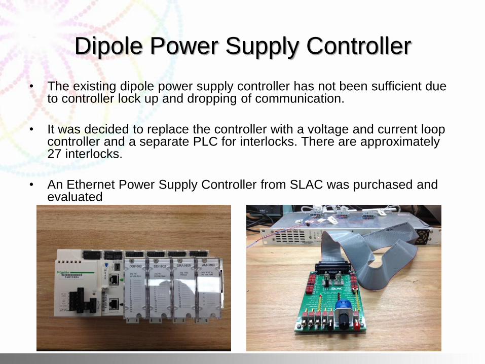
• The existing dipole power supply controller has not been sufficient due to controller lock up and dropping of communication.
• It was decided to replace the controller with a voltage and current loop controller and a separate PLC for interlocks. There are approximately 27 interlocks.
• An Ethernet Power Supply Controller from SLAC was purchased and evaluated
Calibrate septum board between open and
closed loop operation • The Australian Synchrotron is moving to top up mode which requires
repeatable single pulses every two minutes of the septum magnets in addition to continuous 1Hz operation (8000A in 600us).
• The solution to this is to operate the septum magnet in closed loop for 1Hz, and open loop for single pulses.
• During 1Hz ‘full fill’ the system needs to be in closed loop due to temperature drift of the magnet (significantly reduced by a new heatsink) and open loop during ‘top-up’ pulses due to the duration of time between pulses.
• The septum had to be calibrated to bring closed loop operation to within approximately 200ppm of the open loop single pulses. The power supplies were originally rated to ±500ppm.
• A trim pot was used to bring the closed-loop output current to within calibration of the open loop by biasing the error
Calibrate septum board between open and
closed loop operation
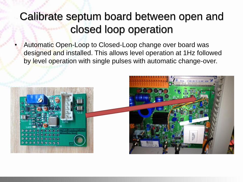
• Automatic Open-Loop to Closed-Loop change over board was
designed and installed. This allows level operation at 1Hz followed
by level operation with single pulses with automatic change-over.
Calibrate septum board between open and
closed loop operation
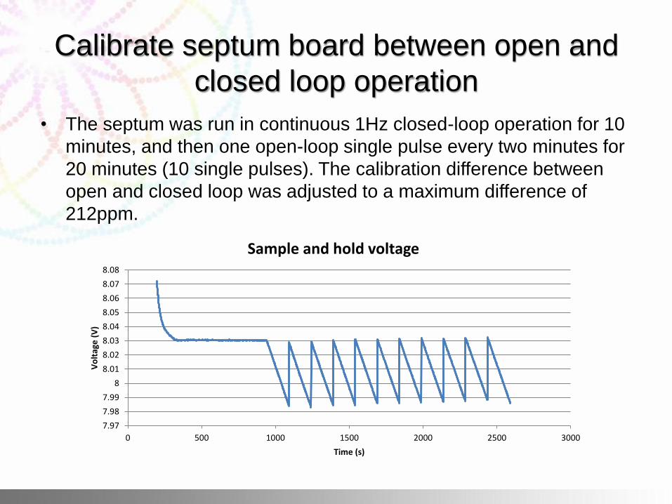
• The septum was run in continuous 1Hz closed-loop operation for 10
minutes, and then one open-loop single pulse every two minutes for
20 minutes (10 single pulses). The calibration difference between
open and closed loop was adjusted to a maximum difference of
212ppm.
7.97
7.98
7.99
8
8.01
8.02
8.03
8.04
8.05
8.06
8.07
8.08
0 500 1000 1500 2000 2500 3000
Vo
ltag
e (
V)
Time (s)
Sample and hold voltage
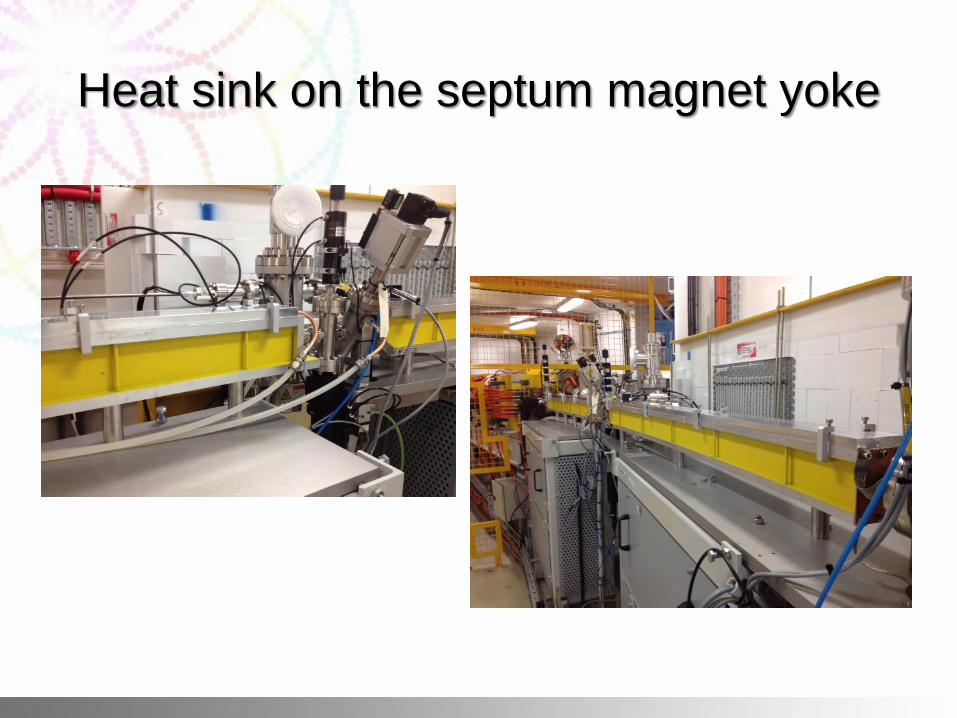
Heat sink on the septum magnet yoke
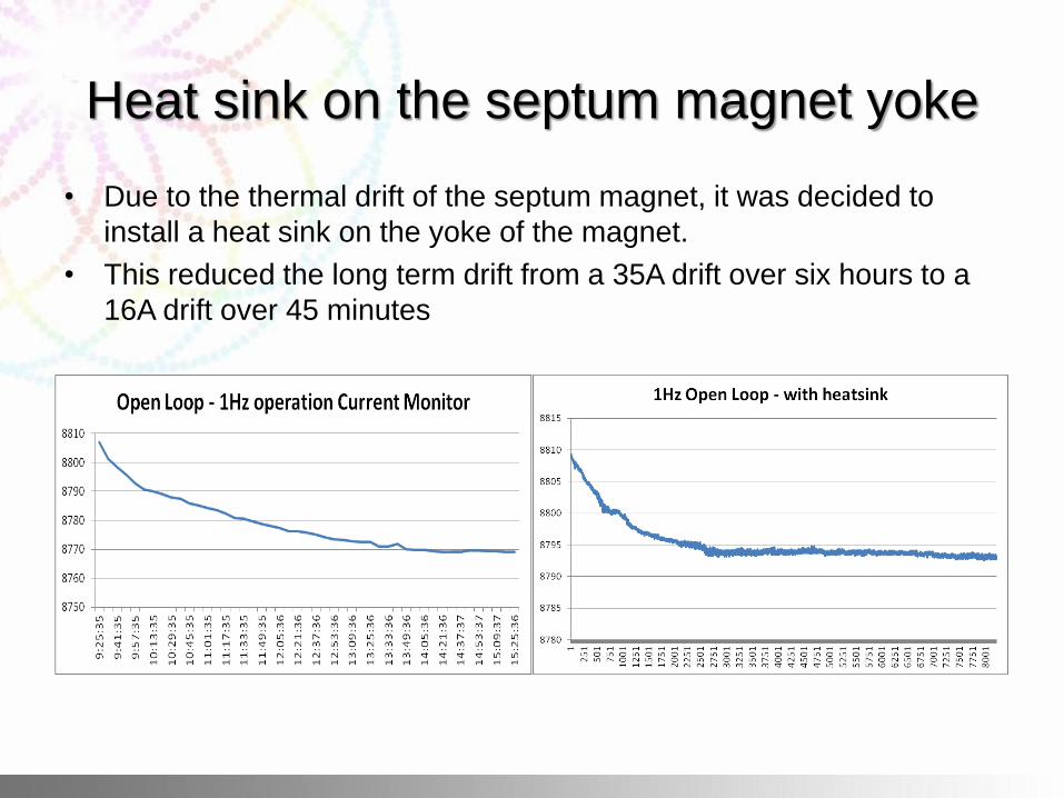
• Due to the thermal drift of the septum magnet, it was decided to
install a heat sink on the yoke of the magnet.
• This reduced the long term drift from a 35A drift over six hours to a
16A drift over 45 minutes
Heat sink on the septum magnet yoke
Shielding of the Septum Magnet controller
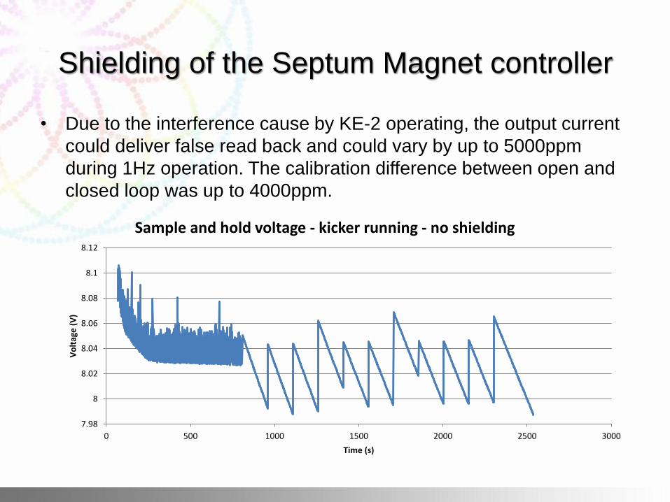
• Due to the interference cause by KE-2 operating, the output current
could deliver false read back and could vary by up to 5000ppm
during 1Hz operation. The calibration difference between open and
closed loop was up to 4000ppm.
7.98
8
8.02
8.04
8.06
8.08
8.1
8.12
0 500 1000 1500 2000 2500 3000
Vo
ltag
e (
V)
Time (s)
Sample and hold voltage - kicker running - no shielding
Shielding of the Septum Magnet controller
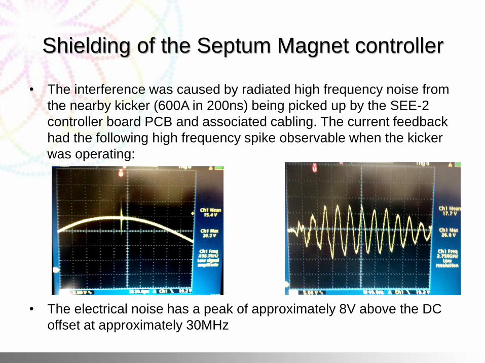
• The interference was caused by radiated high frequency noise from
the nearby kicker (600A in 200ns) being picked up by the SEE-2
controller board PCB and associated cabling. The current feedback
had the following high frequency spike observable when the kicker
was operating:
• The electrical noise has a peak of approximately 8V above the DC
offset at approximately 30MHz
Shielding of the Septum Magnet controller
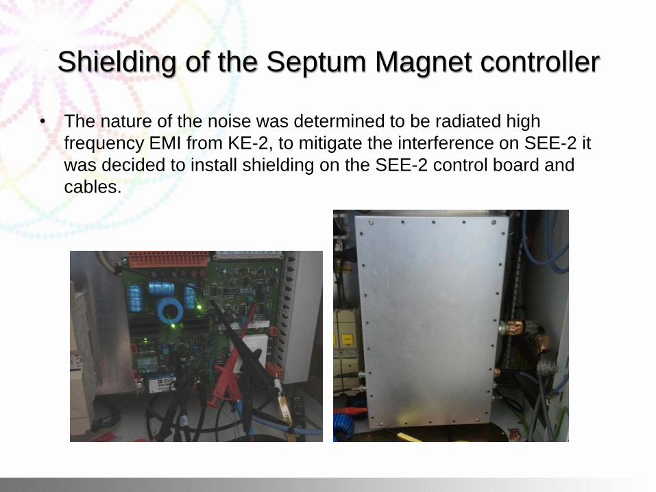
• The nature of the noise was determined to be radiated high
frequency EMI from KE-2, to mitigate the interference on SEE-2 it
was decided to install shielding on the SEE-2 control board and
cables.
Shielding of the Septum Magnet controller
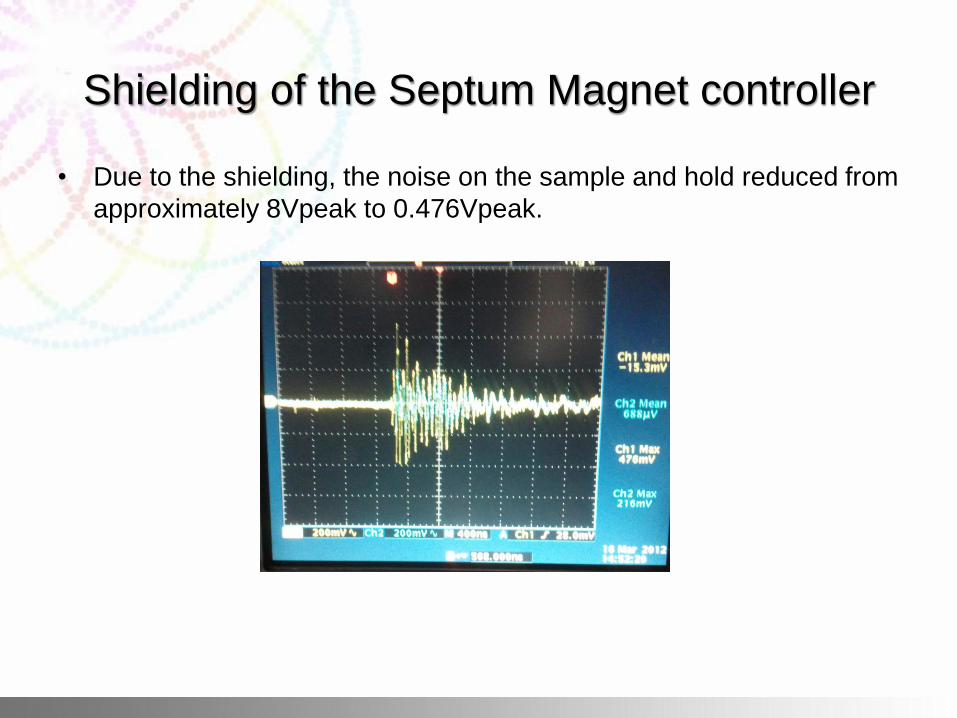
• Due to the shielding, the noise on the sample and hold reduced from
approximately 8Vpeak to 0.476Vpeak.
Shielding of the Septum Magnet controller
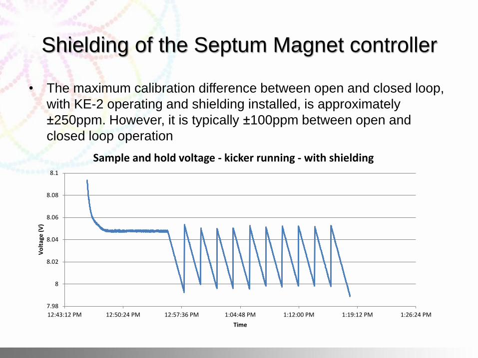
• The maximum calibration difference between open and closed loop,
with KE-2 operating and shielding installed, is approximately
±250ppm. However, it is typically ±100ppm between open and
closed loop operation
7.98
8
8.02
8.04
8.06
8.08
8.1
12:43:12 PM 12:50:24 PM 12:57:36 PM 1:04:48 PM 1:12:00 PM 1:19:12 PM 1:26:24 PM
Vo
ltag
e (
V)
Time
Sample and hold voltage - kicker running - with shielding
Septum Magnet induced currents
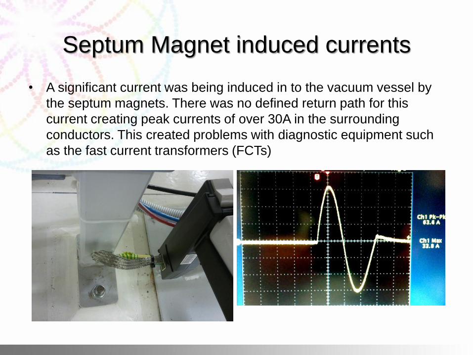
• A significant current was being induced in to the vacuum vessel by
the septum magnets. There was no defined return path for this
current creating peak currents of over 30A in the surrounding
conductors. This created problems with diagnostic equipment such
as the fast current transformers (FCTs)
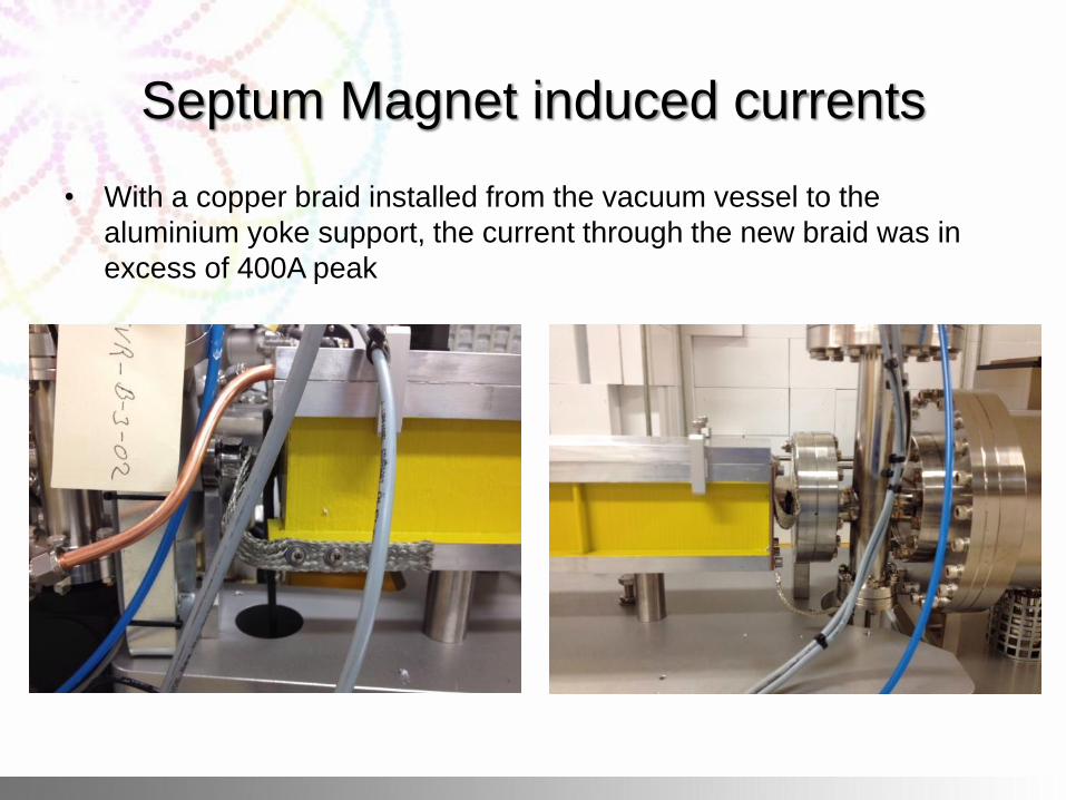
Septum Magnet induced currents
• With a copper braid installed from the vacuum vessel to the
aluminium yoke support, the current through the new braid was in
excess of 400A peak
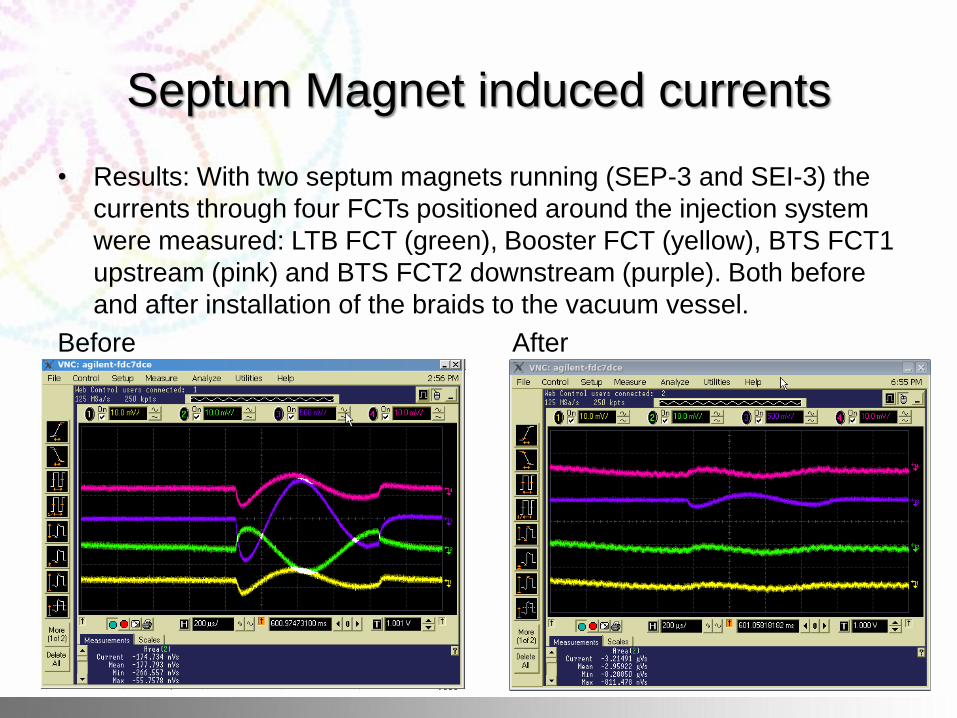
Septum Magnet induced currents
• Results: With two septum magnets running (SEP-3 and SEI-3) the
currents through four FCTs positioned around the injection system
were measured: LTB FCT (green), Booster FCT (yellow), BTS FCT1
upstream (pink) and BTS FCT2 downstream (purple). Both before
and after installation of the braids to the vacuum vessel.
Before After
Kicker Magnet return path
• Originally by design, the return current passed down
vacuum vessel.
• There were other parallel return paths (earth loops)
which caused current to flow throughout the earthing
system and vacuum vessel.
• A better design would be a single connection to earth
and a dual feed through design to keep the magnet
conductor floating.
• The HV is at 18kV and 4kV across the vacuum vessel
was measured.
• Thyratron pulse at 1Hz, 600A peak for 200ns; total time
500ns
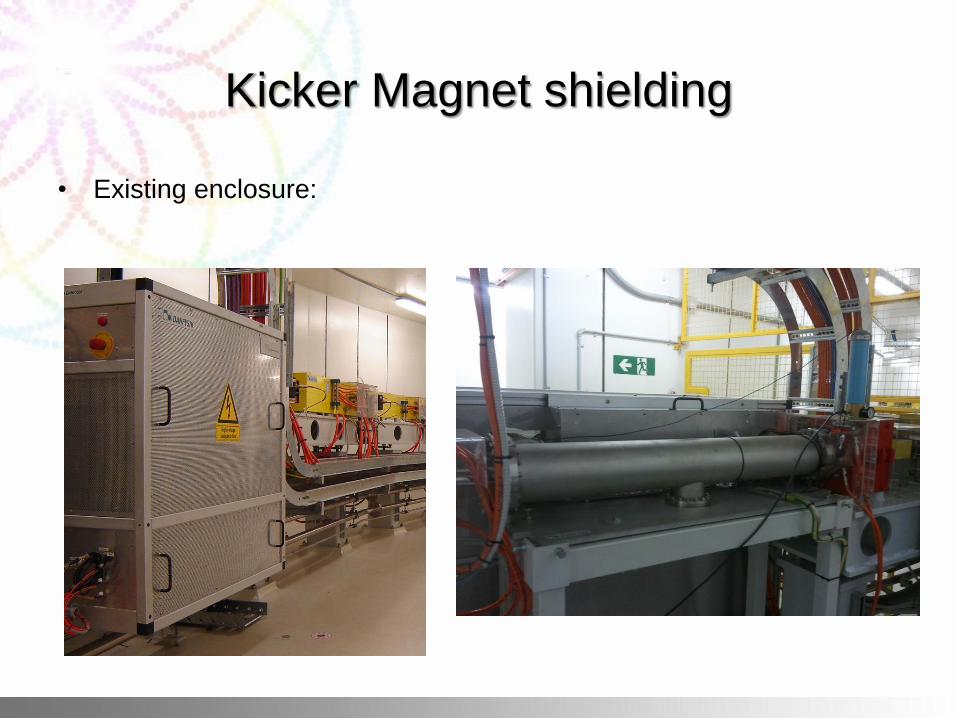
Kicker Magnet shielding
• Existing enclosure:
Kicker Magnet shielding
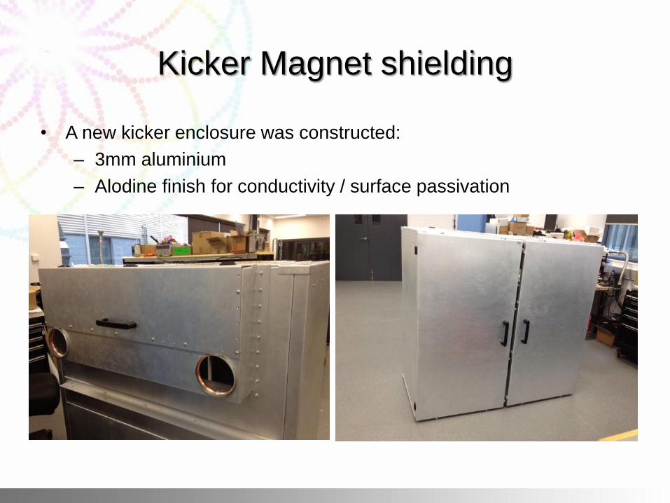
• A new kicker enclosure was constructed:
– 3mm aluminium
– Alodine finish for conductivity / surface passivation
Kicker Magnet shielding
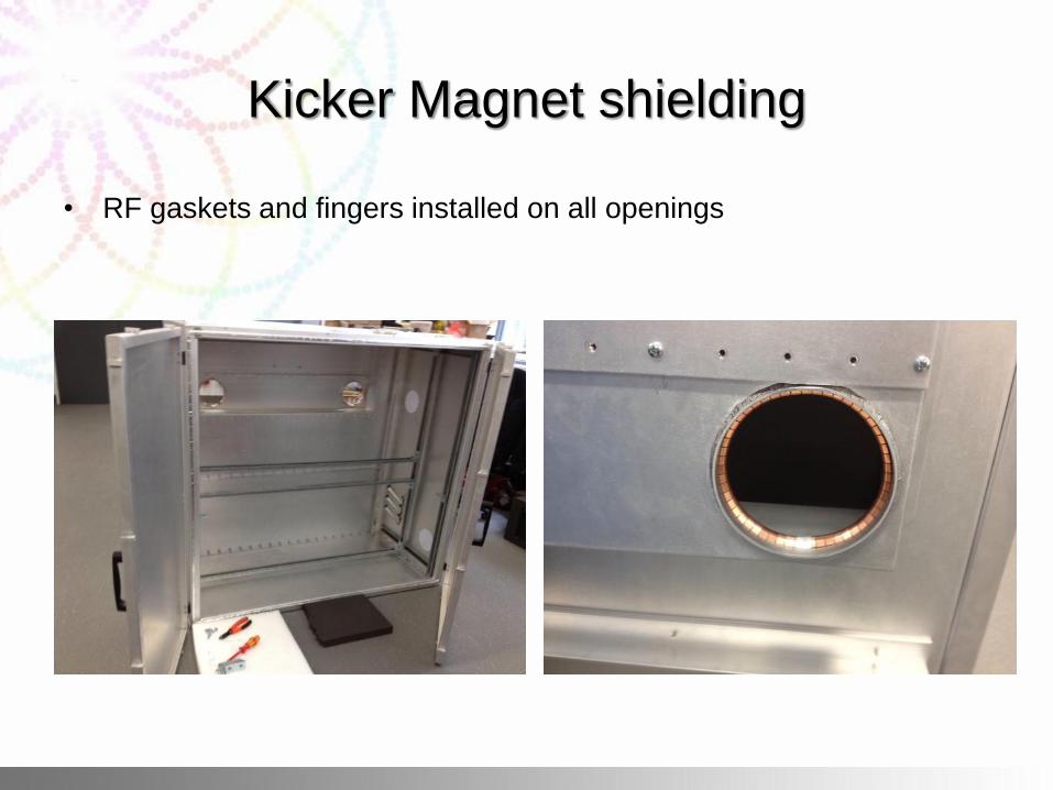
• RF gaskets and fingers installed on all openings
Kicker Magnet shielding
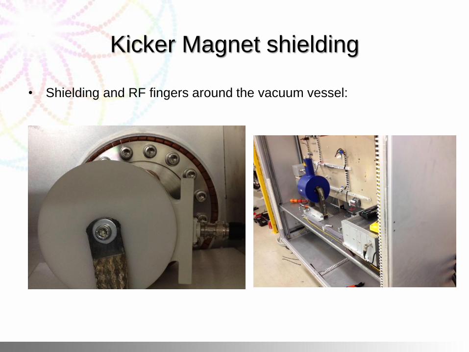
• Shielding and RF fingers around the vacuum vessel:
Kicker Magnet shielding
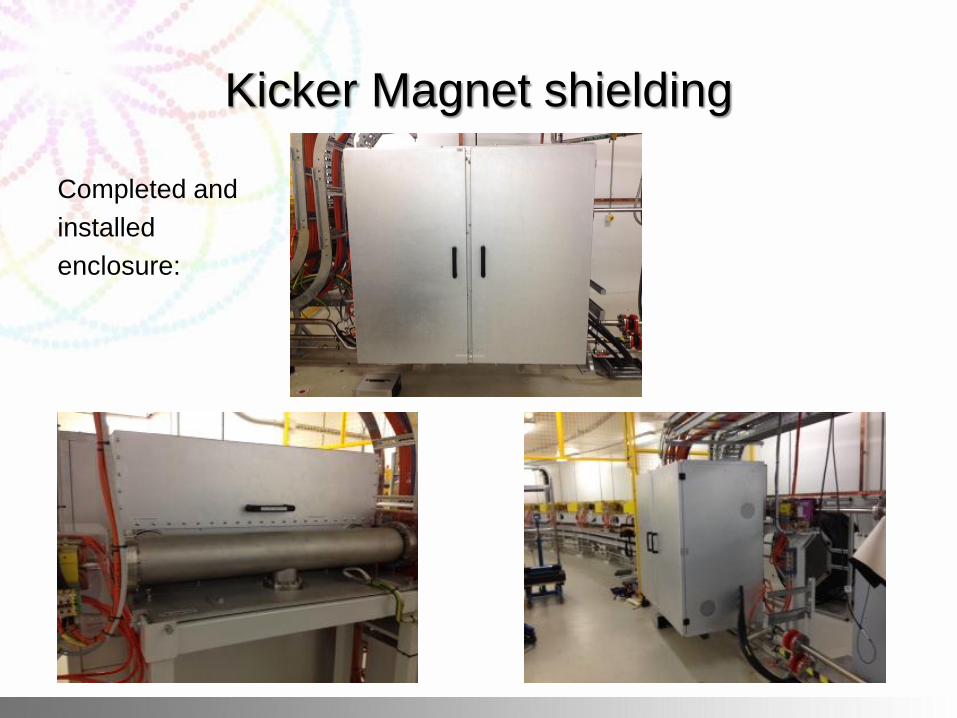
Completed and
installed
enclosure:
Kicker Magnet shielding
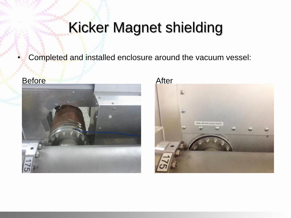
• Completed and installed enclosure around the vacuum vessel:
Before After
Kicker Magnet shielding
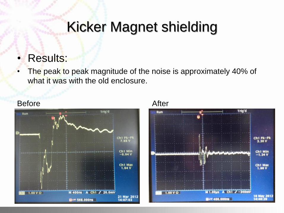
• Results: • The peak to peak magnitude of the noise is approximately 40% of
what it was with the old enclosure.
Before After
New Development – Fast Global Feedback
• Looking at developing in-house low current linear power
supplies with analogue control for the purpose of fast
global feedback.
• FGF has the aim of reducing noise and taking the 50Hz
out of the beam.
• The sextupole yokes may have additional windings
added for the purposes of FGF, so as not to effect the
existing correctors.
• This is still being investigated.
Acknowledgements
• Steve Griffiths
• Wes Hoffman
• Brian Jensen
• Adam Michalczyk
• Noel Basten
• And the rest of the electrical team