Embed Size (px)
Citation preview

請使用封面資料夾中的檔案DEX210 V2_Manual_Cover_Front_Final_Outl ined.ai

.2.
Inhaltsverzeichnis
Before you begin .3.
Assembly .3.
Safety Notes – IMPORTANT .4.
Symbol Reference Key .7.
Assembly Instructions .9.
Exploded View .58.
Parts List Standard Parts .71.
Parts List Option Parts .72.
Team Durango Ltd .75.
.3.
.3.
.5.
.7.
.9.
.58.
.71.
.72.
.75.
Bevor Sie anfangen .3.
Zusammenbau .3.
Sicherheitswarnungen – WICHTIG .5.
Symbol Schlüssel .7.
Montage Anleitung .9.
Explosionsansicht .58.
Ersatzteileliste .71.
Tuningteileliste .72.
Team Durango Ltd .75.
.3.
.3.
.6.
.7.
.9.
.58.
.71.
.72.
.75.
Contents
.3.
DEX210v2
DEX210v2DEX210v2
Team Durango
DEX210v2
DEX210v2Team Durango
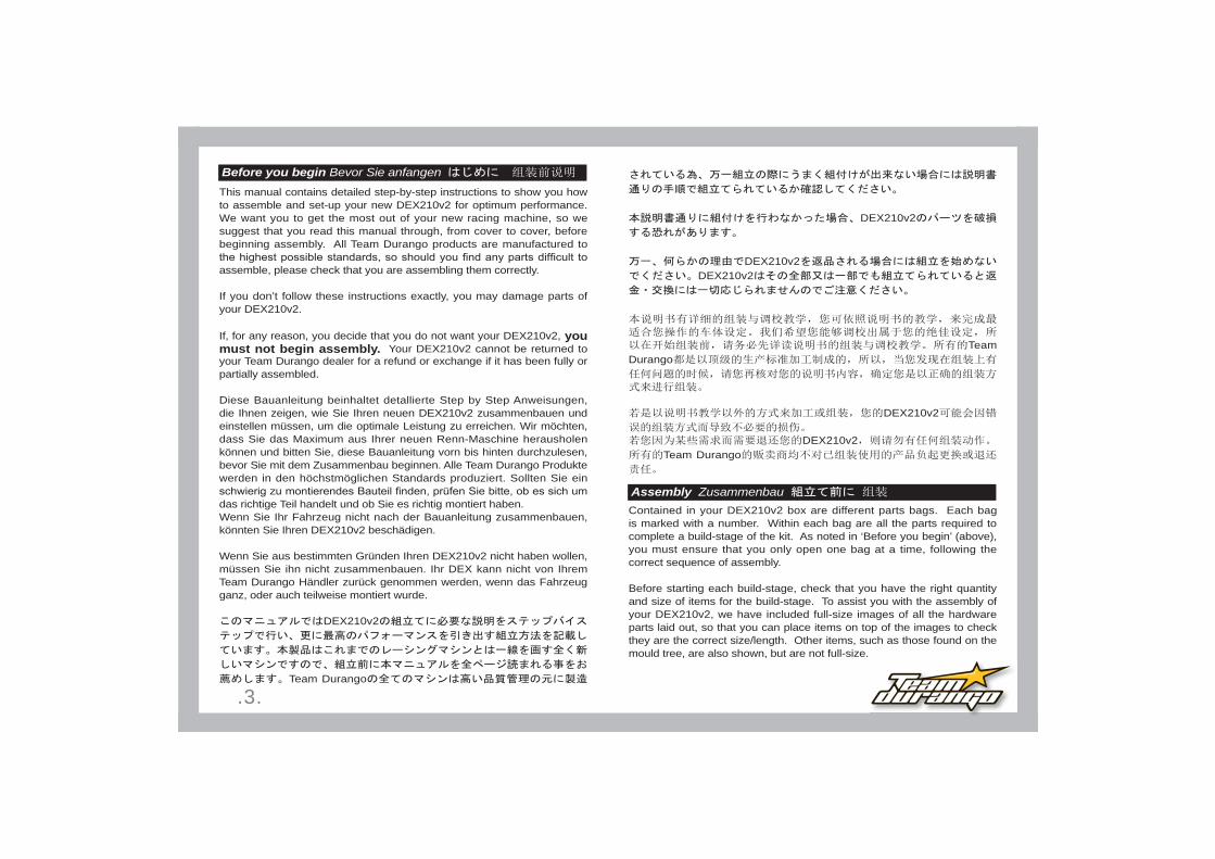
Before you begin Bevor Sie anfangen
Contained in your DEX210v2 box are different parts bags. Each bag is marked with a number. Within each bag are all the parts required to complete a build-stage of the kit. As noted in ‘Before you begin’ (above), you must ensure that you only open one bag at a time, following the correct sequence of assembly.
Before starting each build-stage, check that you have the right quantity and size of items for the build-stage. To assist you with the assembly of your DEX210v2, we have included full-size images of all the hardware parts laid out, so that you can place items on top of the images to check they are the correct size/length. Other items, such as those found on the mould tree, are also shown, but are not full-size.
This manual contains detailed step-by-step instructions to show you how to assemble and set-up your new DEX210v2 for optimum performance. We want you to get the most out of your new racing machine, so we suggest that you read this manual through, from cover to cover, before beginning assembly. All Team Durango products are manufactured to
assemble, please check that you are assembling them correctly.
If you don’t follow these instructions exactly, you may damage parts of your DEX210v2.
If, for any reason, you decide that you do not want your DEX210v2, you must not begin assembly. Your DEX210v2 cannot be returned to your Team Durango dealer for a refund or exchange if it has been fully or partially assembled.
Diese Bauanleitung beinhaltet detallierte Step by Step Anweisungen, die Ihnen zeigen, wie Sie Ihren neuen DEX210v2 zusammenbauen und einstellen müssen, um die optimale Leistung zu erreichen. Wir möchten, dass Sie das Maximum aus Ihrer neuen Renn-Maschine herausholen können und bitten Sie, diese Bauanleitung vorn bis hinten durchzulesen, bevor Sie mit dem Zusammenbau beginnen. Alle Team Durango Produkte werden in den höchstmöglichen Standards produziert. Sollten Sie ein
das richtige Teil handelt und ob Sie es richtig montiert haben.Wenn Sie Ihr Fahrzeug nicht nach der Bauanleitung zusammenbauen, könnten Sie Ihren DEX210v2 beschädigen.
Wenn Sie aus bestimmten Gründen Ihren DEX210v2 nicht haben wollen, müssen Sie ihn nicht zusammenbauen. Ihr DEX kann nicht von Ihrem Team Durango Händler zurück genommen werden, wenn das Fahrzeug ganz, oder auch teilweise montiert wurde.
DEX210v2
Team Durango
Assembly Zusammenbau
.4.
Der Inhalt Ihres DEX210v2 Baukastens enthält verschiede Teile-Beutel. Jeder Beutel ist mit einer Nummer markiert. In jedem Beutel sind genau die Teile, die sie für den Zusammenbau eines Bauabschnittes benötigen. Stellen Sie sicher, dass jeweils immer nur ein Beutel geöffnet ist, folgend der Baustufen.
Bevor Sie mit dem Zusammenbau beginnen, stellen Sie sicher, dass alle benötigten Teile im Beutel enthalten sind. Um Ihnen zu helfen, haben wir alle Teile in Originalgröße abgebildet. So können Sie Ihre Teile im Zweifel auf die Abbildung legen, um die Größe/Dimension zu prüfen. Andere Teile, wie Teile eines Plastik-Baums sind auch zu sehen, aber nicht in voller Größe.
DEX210v2
DEX210v2
DEX210v2
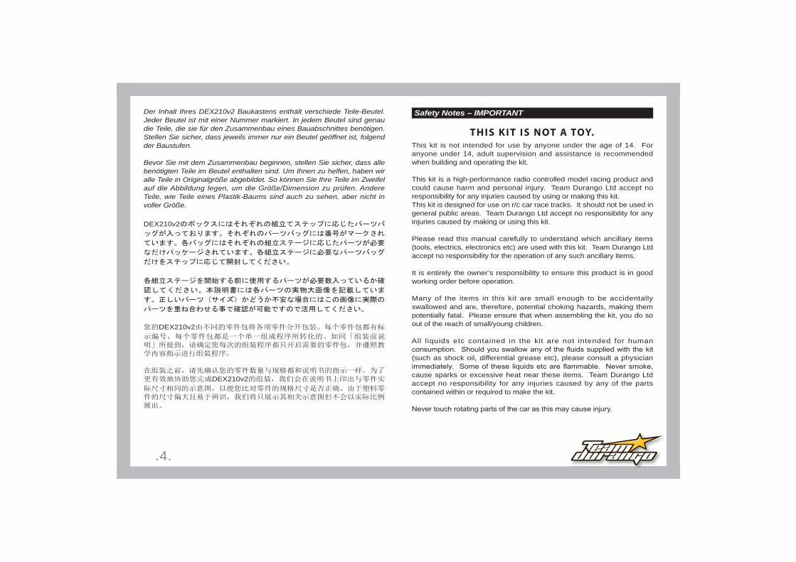
Safety Notes – IMPORTANT
THIS KIT IS NOT A TOY.
This kit is not intended for use by anyone under the age of 14. For anyone under 14, adult supervision and assistance is recommended when building and operating the kit.
This kit is a high-performance radio controlled model racing product and could cause harm and personal injury. Team Durango Ltd accept no responsibility for any injuries caused by using or making this kit.This kit is designed for use on r/c car race tracks. It should not be used in general public areas. Team Durango Ltd accept no responsibility for any injuries caused by making or using this kit.
Please read this manual carefully to understand which ancillary items (tools, electrics, electronics etc) are used with this kit. Team Durango Ltd accept no responsibility for the operation of any such ancillary items.
It is entirely the owner’s responsibility to ensure this product is in good working order before operation.
Many of the items in this kit are small enough to be accidentally swallowed and are, therefore, potential choking hazards, making them potentially fatal. Please ensure that when assembling the kit, you do so out of the reach of small/young children.
All liquids etc contained in the kit are not intended for human
(such as shock oil, differential grease etc), please consult a physician
cause sparks or excessive heat near these items. Team Durango Ltd accept no responsibility for any injuries caused by any of the parts contained within or required to make the kit.

.5.
Do not run your car in poor light or if it goes out of sight. Any impairment to your vision may result in damage to your car or, worse, injury to others or their property.
As a radio controlled device, your car is subject to radio interference from things beyond your control. Any such interference may cause a loss of control of your car, so please consider this possibility at all times.
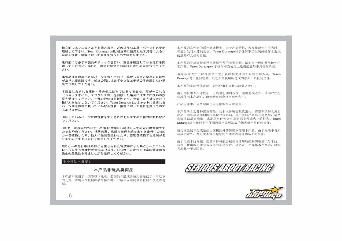
Sicherheitswarnungen – WICHTIG
Dieses Fahr zeug ist kein Spielzeug
Dieser Baukasten ist nicht geeignet für Jugendliche unter 14 Jahren. Bei Jugendlichen unter 14 Jahren muss eine erwachsene Person für den Zusammenbau und den Betrieb des Modells anwesend sein.
Dieses Modell ist ein Hochleistung Wettbewerbsfahrzeug und könnte erheblichen Schaden und Verletzungen hervorrufen. Team Durango Ltd übernimmt keinerlei Haftung für eventuelle Schaden, die beim Zusammenbau, oder Betrieb des Modells hervorgerufen werden.
Dieses Modell ist für den Betrieb auf Rennstrecken ausgelegt. Es sollte nicht auf öffentlichen Bereichen betrieben werden. Team Durango Ltd übernimmt keine Verantwortung für den Zusammenbau, oder Betrieb dieses Modells.
Bitte lesen Sie die Bauanleitung genau durch, um sicherzustellen, welche weiteren Werkzeuge, oder Elektronik zum Zusammenbau und Betrieb des Modells notwendig sind. Team Durango übernimmt keine Verantwortung für den Gebrauch dieser zusätzlichen Gegenstände.
Für den einwandfreien Zusammenbau und Betrieb ist Modells ist alleinig der Besitzer verantwortlich.
Einige der Bauteile sind sehr klein und könnten eingeatmet werden, was Erstickungen hervorrufen könnte. Stellen Sie sicher, dass keine Kleinkinder in die Nähe des Arbeitsbereichen kommen können.
Alle Flüssigkeiten des Baukastens sind nicht zum Verzehr geeignet. Sollten Sie eine Flüssigkeit versehendlich verschlucken, begeben Sie sich sofort zum Arzt.Einige Teile des Baukastens sind leicht entzündlich. Rauchen Sie niemals beim Zusammenbau und Betrieb dieses Modells. Funken könnten Teile des Modells entzünden. Team Durango Ltd übernimmt keine Verantwortung für Verletzungen, die während des Zusammenbaus, oder Betrieb des Modells durch diese Dinge hervorgerufen werden können.
Berühren Sie niemals rotierende Teile des Modells. Dies könnte ernsthafte Verletzungen hervorrufen.
Betreiben Sie niemals das Modell bei schlechten Licht, oder wenn es außer Sichtweite ist. Jede Störung Ihrer Sicht, kann Ihr Modell beschädigen, oder schlimmer noch, Personen, oder Eigentum beschädigen.
Als ferngesteuertes Modell kann Ihr Modell Interferenzen ausgesetzt sein, die die Kontrolle des Modells stören können. Jegliche Interferenz kann Ihr Modell außer Kontrolle bringen. Bitte beachten Sie stets diesen Umstand.
14 13
Team Durango Ltd
.6.
Team Durango
Team Durango
Team Durango
Team Durango
Team Durango Ltd
R/C
Team Durango Ltd
R/CR/C
R/C R/CR/C
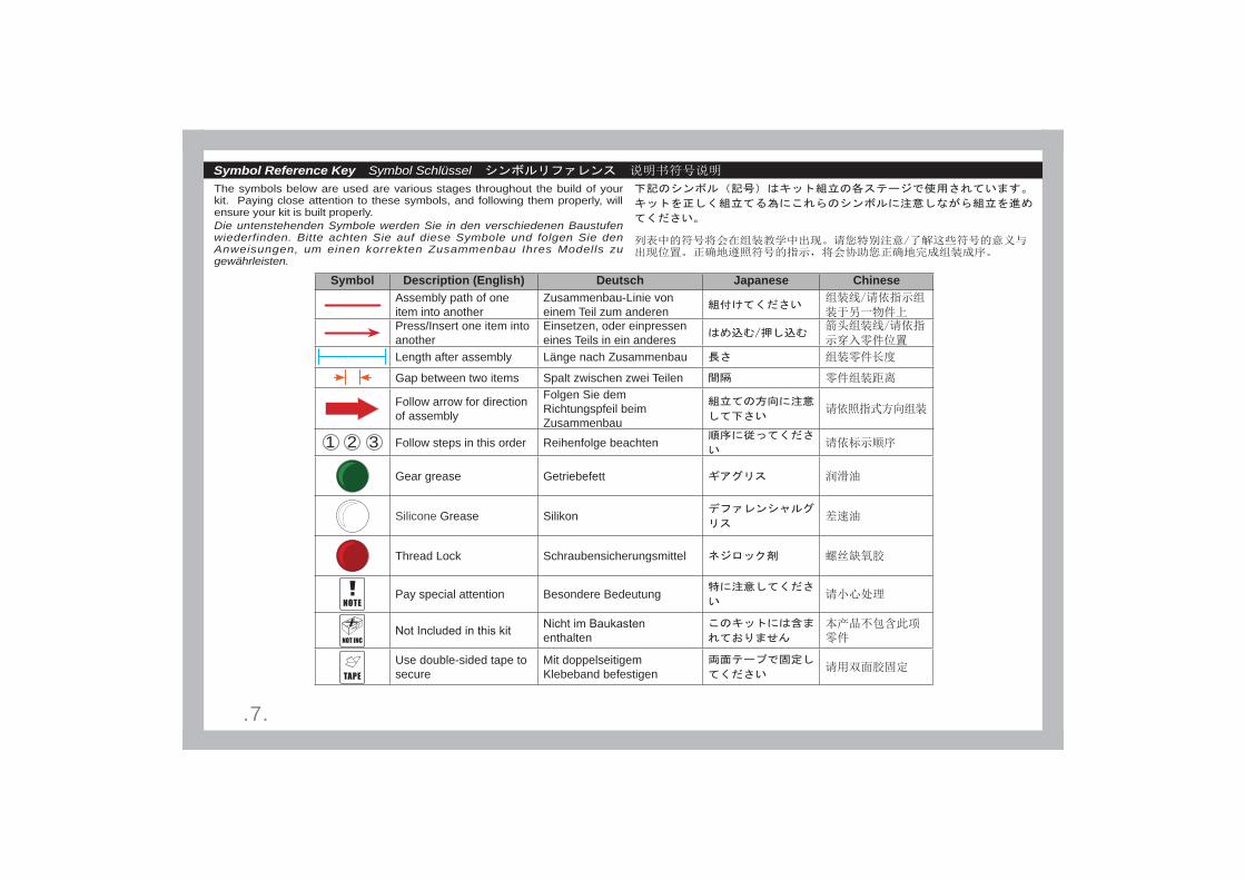
Symbol Description (English) Deutsch Japanese ChineseAssembly path of one item into another
Zusammenbau-Linie von einem Teil zum anderen
Press/Insert one item into another
Einsetzen, oder einpressen eines Teils in ein anderes
Length after assembly Länge nach Zusammenbau
Gap between two items Spalt zwischen zwei Teilen
Follow arrow for direction of assembly
Folgen Sie dem Richtungspfeil beim Zusammenbau
Follow steps in this order Reihenfolge beachten
Gear grease Getriebefett
Silicone Grease Silikon
Thread Lock Schraubensicherungsmittel
Pay special attention Besondere Bedeutung
enthalten
Use double-sided tape to secure
Mit doppelseitigem Klebeband befestigen
.7.
The symbols below are used are various stages throughout the build of your kit. Paying close attention to these symbols, and following them properly, will ensure your kit is built properly.Die untenstehenden Symbole werden Sie in den verschiedenen Baustufen wiederfinden. Bitte achten Sie auf diese Symbole und folgen Sie den Anweisungen, um einen korrekten Zusammenbau Ihres Modells zu gewährleisten.
321
Symbol Reference Key Symbol Schlüssel

.8.
Transmitter
Required items (not included in k it)
ReceiverS er vo
Cross Wrench
M 3 m mM 4 m m
Control ler
Hex Driver
1 . 5 m m
1 . 3 m m / 0 . 0 5 i n c h
2 m m 2 . 5 m m
Needlenose Pl iers
Diff and Shock Oil
Batter y Charger
M o tor
AA Batter y
2S LiPO batter y
64dp Pinion
Double -sided Tape
TyresInser ts
C A glue

.9.
Assembly Instruc tions

.10.
1:1
A1
C S M 3 x 6 m m7 0 4 0 0 4 x 2
7 0 4 0 0 6
7 0 4 0 0 4
7 0 4 0 0 4
7 0 4 0 0 6
3 2 0 2 1 5 - 2
3 2 0 2 1 5 - 1
3 2 0 2 4 0
7 0 4 0 0 6
7 0 4 0 0 6
3 2 0 2 6 9 - 4
7 0 4 0 0 6
7 0 4 0 0 6
C S M 3 x 8 m m7 0 4 0 0 6 x 8
A
.11.
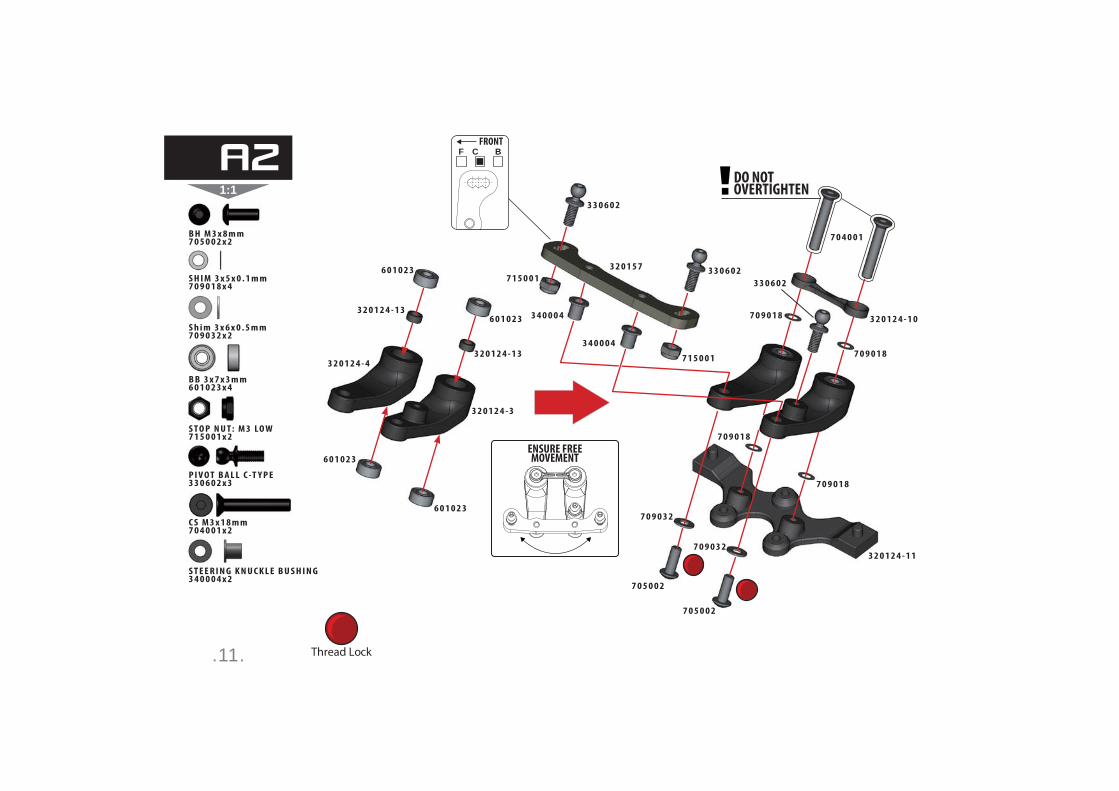
1:1DO NOTOVERTIGHTEN
ENSURE FREEMOVEMENT
F C BFRONT
Thread Lock
S T E E R I N G K N U C K L E B U S H I N G3 4 0 0 0 4 x 2
S T O P N U T : M 3 LO W7 1 5 0 0 1 x 2
P I V O T B A L L C -T Y P E3 3 0 6 0 2 x 3
C S M 3 x 1 8 m m7 0 4 0 0 1 x 2
B H M 3 x 8 m m7 0 5 0 0 2 x 2
B B 3 x 7 x 3 m m6 0 1 0 2 3 x 4
S H I M 3 x 5 x 0 . 1 m m7 0 9 0 1 8 x 4
S h i m 3 x 6 x 0 . 5 m m 7 0 9 0 3 2 x 2
3 4 0 0 0 4
3 4 0 0 0 4
7 1 5 0 0 1
7 1 5 0 0 1
3 2 0 1 5 7
3 3 0 6 0 2
3 3 0 6 0 2
3 3 0 6 0 2
7 0 4 0 0 1
7 0 5 0 0 2
7 0 5 0 0 2
7 0 9 0 3 2
7 0 9 0 3 26 0 1 0 2 3
6 0 1 0 2 3
6 0 1 0 2 3
6 0 1 0 2 3
3 2 0 1 2 4 - 1 3
3 2 0 1 2 4 - 1 3
3 2 0 1 2 4 - 1 1
3 2 0 1 2 4 - 1 0
3 2 0 1 2 4 - 3
3 2 0 1 2 4 - 47 0 9 0 1 8
7 0 9 0 1 8
7 0 9 0 1 8
7 0 9 0 1 8
A2

.12.
1:1
C S M 3 x 6 m m7 0 4 0 0 4 x 3
7 0 4 0 0 47 0 4 0 0 4
7 0 4 0 0 4
A3
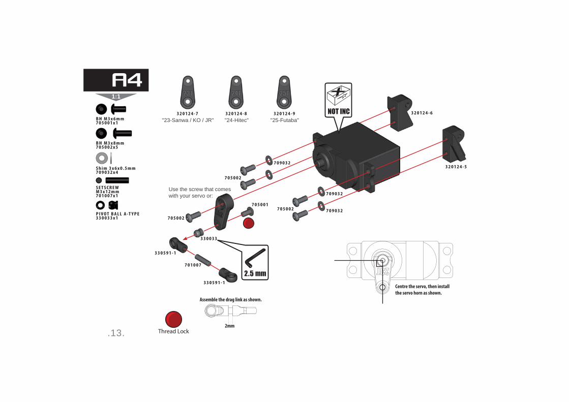
.13.
1:1
3 2 0 1 2 4 - 7 3 2 0 1 2 4 - 8 3 2 0 1 2 4 - 9
"23-Sanwa / KO / JR" "24-Hitec" "25-Futaba"
Centre the servo, then install
the servo horn as shown.
2mm
Assemble the drag link as shown.
Thread Lock
B H M 3 x 8 m m7 0 5 0 0 2 x 5
S E T S C R E W M 3 x 1 2 m m7 0 1 0 0 7 x 1
B H M 3 x 6 m m7 0 5 0 0 1 x 1
P I V O T B A L L A -T Y P E3 3 0 0 3 3 x 1
S h i m 3 x 6 x 0 . 5 m m 7 0 9 0 3 2 x 4
7 0 5 0 0 2
7 0 1 0 0 7
3 3 0 5 9 1 - 1
3 3 0 5 9 1 - 1
3 3 0 0 3 3
3 2 0 1 2 4 - 6
3 2 0 1 2 4 - 5
7 0 5 0 0 1
7 0 9 0 3 2
7 0 9 0 3 2
7 0 9 0 3 2
7 0 5 0 0 2
7 0 5 0 0 2
Use the screw that comeswith your servo or:
A4
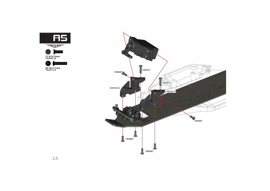
.14.
1:1
C S M 3 x 1 0 m m7 0 4 0 0 7 x 6
B H M 3 x 1 4 m m7 0 5 0 1 1 x 2 7 0 5 0 1 1
7 0 4 0 0 7
7 0 4 0 0 7
7 0 4 0 0 7
7 0 4 0 0 7
3 2 0 1 2 4 - 1
3 2 0 1 2 4 - 2
7 0 5 0 1 1
A5

.15.
1:11
2mm2
C S M 3 x 1 8 m m7 0 4 0 0 1 x 4
C S M 3 x 1 4 m m7 0 4 0 0 5 x 4
P i v o t B a l l C -Ty p e 1 0 m m L o n g3 3 0 6 0 1 x 2
C S M 3 x 1 2 m m7 0 4 0 0 3 x 2
7 0 4 0 0 5
7 0 4 0 0 5
7 0 4 0 0 1
7 0 4 0 0 3
7 0 4 0 0 3
3 2 0 1 2 3 - 2
3 2 0 1 2 3 - 2
3 2 0 1 2 3 - 1
3 3 0 5 7 8 - 43 3 0 5 9 8 - 1
3 3 0 6 0 1
3 3 0 3 6 3 - 1
3 3 0 3 6 3 - 1
3 3 0 6 0 1
B1
B

.16.
1:1
Set droop screws level
with wishbone as shown
3 5 m m
1:1
3 3 0 3 5 2
B H M 3 x 1 0 m m7 0 5 0 0 5 x 2
S E T S C R E W M 4 x 8 m m7 0 1 0 1 0 x 2
7 0 5 0 0 5
3 3 0 3 5 2 7 0 1 0 1 0
3 3 0 5 9 4 - 1
3 3 0 5 9 4 - 2
3 3 0 3 4 83 2 0 2 6 9 - 2
B2
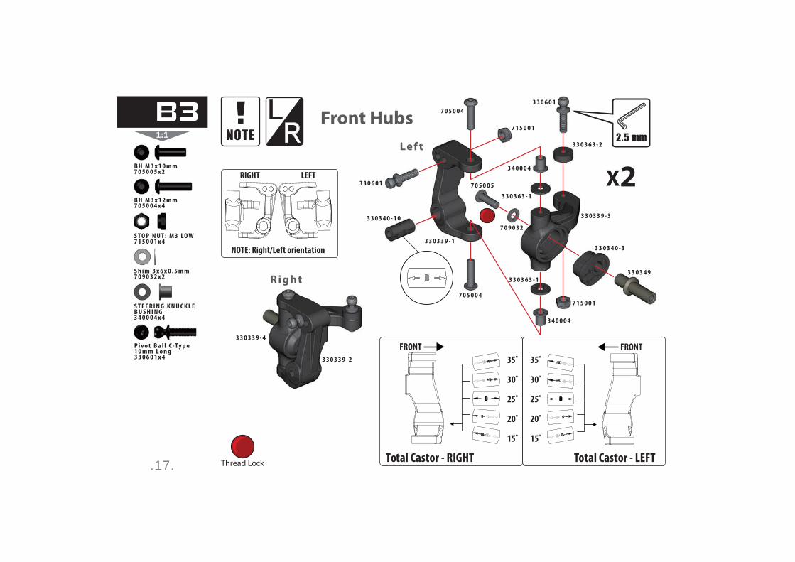
.17.
1:1
LR
35˚
30˚
25˚
20˚
15˚
Total Castor - LEFT
FRONT
35˚
30˚
25˚
20˚
15˚
Total Castor - RIGHT
FRONT
NOTE: Right/Left orientation
LEFTRIGHT
Thread Lock
3 3 0 3 4 9
3 3 0 3 4 0 - 3
3 3 0 3 3 9 - 4
3 3 0 3 3 9 - 2
R ight
Lef t
S T E E R I N G K N U C K L E B U S H I N G3 4 0 0 0 4 x 4
S T O P N U T : M 3 LO W7 1 5 0 0 1 x 4
B H M 3 x 1 0 m m7 0 5 0 0 5 x 2
B H M 3 x 1 2 m m7 0 5 0 0 4 x 4
S h i m 3 x 6 x 0 . 5 m m 7 0 9 0 3 2 x 2
X23 3 0 6 0 1
3 3 0 6 0 1
3 3 0 3 6 3 - 1
3 3 0 3 6 3 - 1
3 3 0 3 6 3 - 2
3 3 0 3 3 9 - 3
3 3 0 3 3 9 - 1
3 3 0 3 4 0 - 1 0
7 0 5 0 0 4
7 0 5 0 0 4
7 1 5 0 0 1
7 1 5 0 0 1
3 4 0 0 0 4
3 4 0 0 0 4
7 0 5 0 0 5
7 0 9 0 3 2
Front Hubs
P i v o t B a l l C -Ty p e 1 0 m m L o n g3 3 0 6 0 1 x 4
B3

.18.
1:1
1:1
3 3 0 3 5 3
2 5 m m4mm
B H M 2 . 5 x 4 m m7 0 5 0 2 9 x 4
7 0 5 0 2 9
7 0 5 0 2 9
3 3 0 3 5 33 3 0 3 6 3 - 1
X2
B4

.19.
1:1
LR
1
2 3
4
LEFT
RIGHT
Gear Grease
3 3 0 3 3 9 - 5
R ight
R O L L P I N 1 . 6 x 1 4 m m3 1 0 1 3 5 x 2
B B M 5 x 1 3 x 4 m m6 0 1 0 1 7 x 2
B B 1 0 x 1 5 x 4 m m6 0 1 0 0 3 x 2
D R I V E S H A F T B U S H I N G ( 2 . 0 m m )3 1 0 1 1 3 x 2
D R I V E S H A F T P I N A -T Y P E 2 . 0 m m3 1 0 1 2 3 x 2
3 3 0 3 1 2 - 27 0 9 0 1 5
3 1 0 1 3 5
3 3 0 6 0 2
3 3 0 3 4 0 - 8
6 0 1 0 0 3
6 0 1 0 1 7
3 3 0 3 6 3 - 1
3 3 0 3 3 9 - 6
3 1 0 2 5 4
3 1 0 1 1 3
3 1 0 1 2 3
3 1 0 4 3 7
Lef t
X2P I V O T B A L L C -T Y P E3 3 0 6 0 2 x 2
S h i m 5 x 7 x 0 . 2 m m7 0 9 0 1 5 x 4
C1
C
R-1.5
R-1
R-0.
5
R+1.5
R+1
R-0.
5
-0
LEFT RIGHT
1.52.02.53.03.54.04.5
TOTAL TOE-IN
1.52 .0 2.5 3.03 .5 4.0 4.5
TOTAL TOE-IN
TOE-IN INSERT SYSTEM
Pay close attention to orientation of inserts
to correctly set optional toe-in.
L+1.5
L+1
L+0.5 +0
L-0.5 L-1
L-1.5
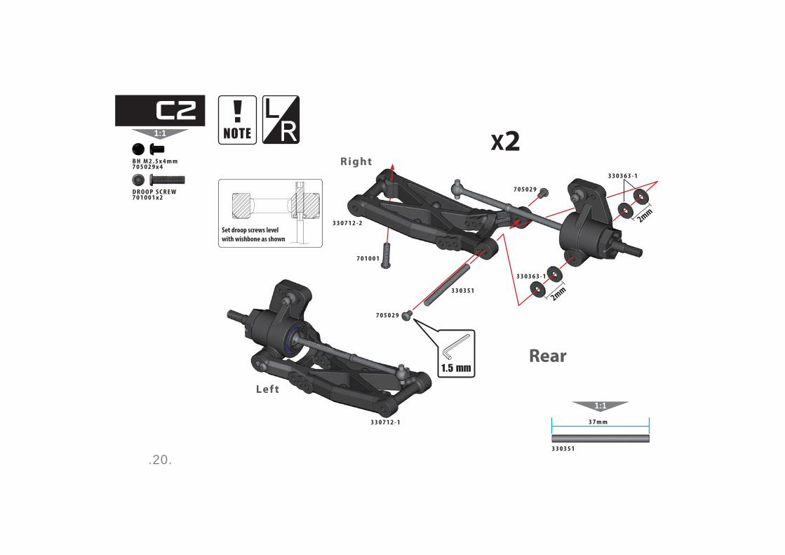
.20.
1:1
LR
1:1
3 3 0 3 5 1
3 7 m m
Set droop screws level
with wishbone as shown
2mm
2mm
B H M 2 . 5 x 4 m m7 0 5 0 2 9 x 4
D R O O P S C R E W7 0 1 0 0 1 x 2
7 0 1 0 0 1
3 3 0 3 5 1
3 3 0 3 6 3 - 1
3 3 0 3 6 3 - 1
3 3 0 7 1 2 - 1
3 3 0 7 1 2 - 2
7 0 5 0 2 9
7 0 5 0 2 9
R ight
Lef t
X2
Rear
C2

.21.
1:1
1:1
3 3 0 3 5 0
4 1 m m
Thread Lock
3 3 0 3 6 3 - 1
7 0 9 0 3 2
C S M 3 x 1 0 m m7 0 4 0 0 7 x 2
P I V O T- B A L L A - A R M3 3 0 0 3 7 x 2
3 3 0 0 3 7
3 3 0 5 9 9
3 3 0 5 7 8 - 1
7 0 4 0 0 7
3 3 0 3 5 0
7 0 4 0 0 6
7 0 4 0 0 6
7 0 4 0 0 7
C3
C S M 3 x 8 m m7 0 4 0 0 6 x 2
S h i m 3 x 6 x 0 . 5 m m 7 0 9 0 3 2 x 2
.22.
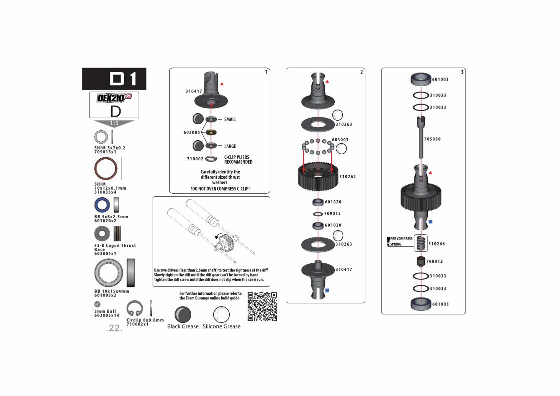
1:1
For further information please refer to the Team Durango online build guide:
SMALL
LARGE
C-CLIP PLIERSRECOMMENDED
31 2
Black Grease Silicone Grease
PRE-COMPRESS
SPRING
B B 1 0 x 1 5 x 4 m m6 0 1 0 0 3 x 2
S H I M 1 0 x 1 2 x 0 . 1 m m3 1 0 0 3 3 x 4
B B 5 x 8 x 2 . 5 m m6 0 1 0 2 0 x 2
S H I M 5 x 7 x 0 . 27 0 9 0 1 5 x 1
F 3 - 8 C a g e d T h r u s t R a c e6 0 3 0 0 5 x 1
3 m m B a l l6 0 3 0 0 3 x 1 4
C i r c l i p 8 x 0 . 8 m m7 1 0 0 0 2 x 1
7 0 8 0 1 2
3 1 0 2 6 6
6 0 1 0 0 3
6 0 1 0 0 3
7 0 5 0 3 0
3 1 0 0 3 3
3 1 0 0 3 3
3 1 0 0 3 3
3 1 0 0 3 3
3 1 0 4 1 7
3 1 0 4 1 7
6 0 3 0 0 3
3 1 0 2 6 2
6 0 1 0 2 0
7 0 9 0 1 5
3 1 0 2 6 3
3 1 0 2 6 3
6 0 1 0 2 0
7 1 0 0 0 2
6 0 3 0 0 5
D
D1

.23.
1:1
For rear motor follow steps on left side pages
For mid motor follow steps on right side pages
w w w.team- durango.com/dex210-motor- config

.24.
1:1
Gear Grease
S h i m 3 x 6 x 0 . 5 m m 7 0 9 0 3 2 x 2
2 0 t L a y s h a f t G e a r2 1 0 0 3 3 x 1
3 4 T I d l e r G e a r3 1 0 2 3 8 x 1
B B 5 x 1 0 x 4 m m6 0 1 0 0 2 x 2
I d l e r G e a r P i n3 1 0 2 4 7 x 1
B B 5 x 8 x 2 . 5 m m6 0 1 0 2 2 x 1
B H M 3 x 1 5 m m7 0 5 0 0 3 x 1
I d l e r G e a r S h i m 5 x 8 x 0 . 5 M M7 0 9 0 3 3 x 2
B H M 3 x 2 2 m m7 0 5 0 1 3 x 1
2 1 0 0 3 3
3 1 0 2 3 8
3 1 0 4 5 9 - 1 3 1 0 4 5 9 - 2
6 0 1 0 0 2
7 0 9 0 3 3
3 1 0 2 4 7
2 1 0 0 3 3
7 0 9 0 3 2
7 0 5 0 0 3
7 0 5 0 1 3
6 0 1 0 2 2
E
E1
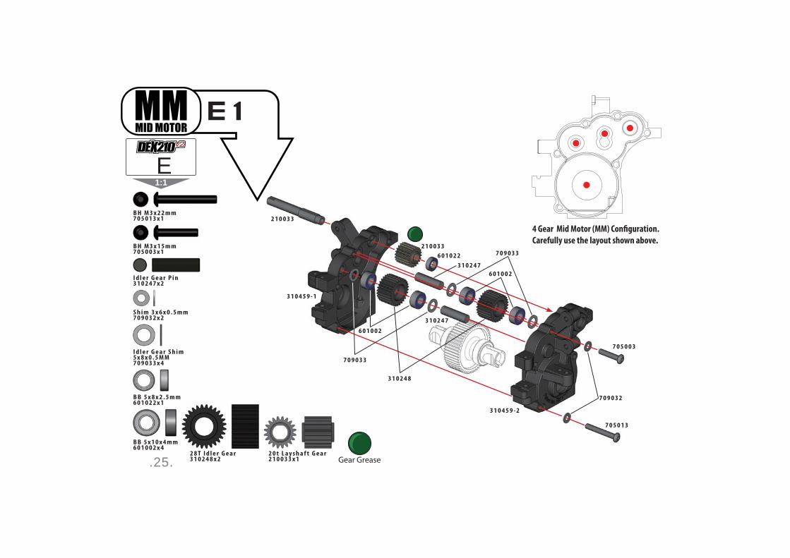
.25.
1:1
2 0 t L a y s h a f t G e a r2 1 0 0 3 3 x 1
2 8 T I d l e r G e a r3 1 0 2 4 8 x 2 Gear Grease
S h i m 3 x 6 x 0 . 5 m m 7 0 9 0 3 2 x 2
B B 5 x 1 0 x 4 m m6 0 1 0 0 2 x 4
I d l e r G e a r P i n3 1 0 2 4 7 x 2
B B 5 x 8 x 2 . 5 m m6 0 1 0 2 2 x 1
B H M 3 x 1 5 m m7 0 5 0 0 3 x 1
B H M 3 x 2 2 m m7 0 5 0 1 3 x 1
I d l e r G e a r S h i m 5 x 8 x 0 . 5 M M7 0 9 0 3 3 x 4
2 1 0 0 3 3
2 1 0 0 3 3
3 1 0 2 4 8
3 1 0 4 5 9 - 1
3 1 0 4 5 9 - 2
7 0 9 0 3 3
7 0 9 0 3 3
6 0 1 0 0 2
6 0 1 0 0 2
3 1 0 2 4 7
3 1 0 2 4 7
6 0 1 0 2 2
7 0 5 0 0 3
7 0 5 0 1 3
7 0 9 0 3 2
E1
E
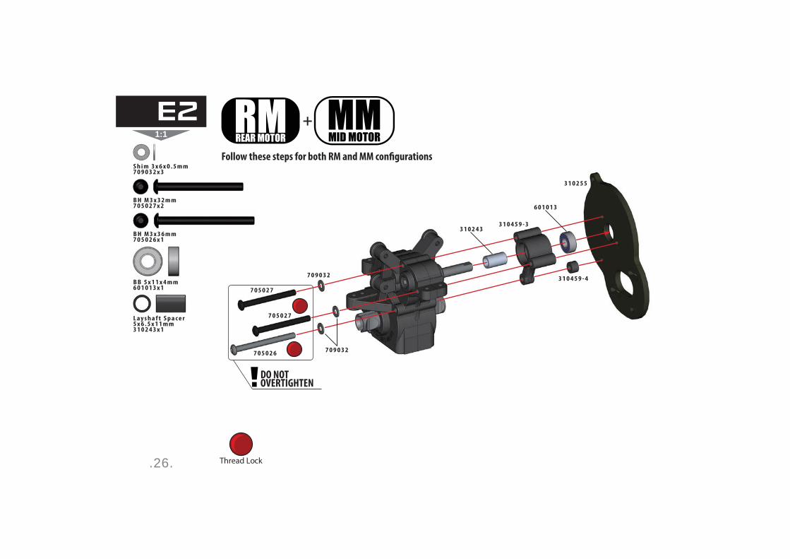
.26.
1:1+
DO NOTOVERTIGHTEN
Thread Lock
S h i m 3 x 6 x 0 . 5 m m 7 0 9 0 3 2 x 3
B H M 3 x 3 6 m m7 0 5 0 2 6 x 1
B H M 3 x 3 2 m m7 0 5 0 2 7 x 2
L a y s h a f t S p a c e r5 x 6 . 5 x 1 1 m m3 1 0 2 4 3 x 1
B B 5 x 1 1 x 4 m m6 0 1 0 1 3 x 1 7 0 5 0 2 7
7 0 5 0 2 7
7 0 9 0 3 2
7 0 9 0 3 27 0 5 0 2 6
3 1 0 2 5 5
3 1 0 2 4 3
6 0 1 0 1 3
3 1 0 4 5 9 - 3
3 1 0 4 5 9 - 4
E2
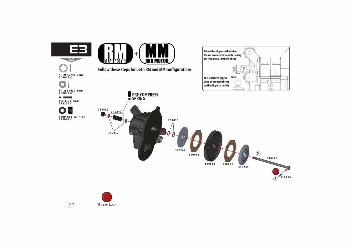
.27.
1:1
1
2
+
PRE-COMPRESSSPRING
2mm
Adjust the slipper so that when
the car accelerates from stationary
there is a small amount of slip
This will leave approx
2mm of exposed thread
on the slipper assembly
Thread Lock
S h i m 3 x 6 x 0 . 5 m m 7 0 9 0 3 2 x 2
S T O P N U T : M 3 H I G H7 1 5 0 0 2 x 1
P i n 1 . 5 x 7 m m3 1 0 2 3 9 x 1
3 1 0 2 3 9
7 1 5 0 0 2
7 0 9 0 3 2
3 1 0 2 4 0
3 1 0 2 4 4
7 0 9 0 1 5
3 1 0 0 3 1
3 1 0 0 3 13 1 0 3 6 23 1 0 2 4 4
3 1 0 2 4 6
S H I M 5 x 7 x 0 . 2 m m7 0 9 0 1 5 x 2
E3
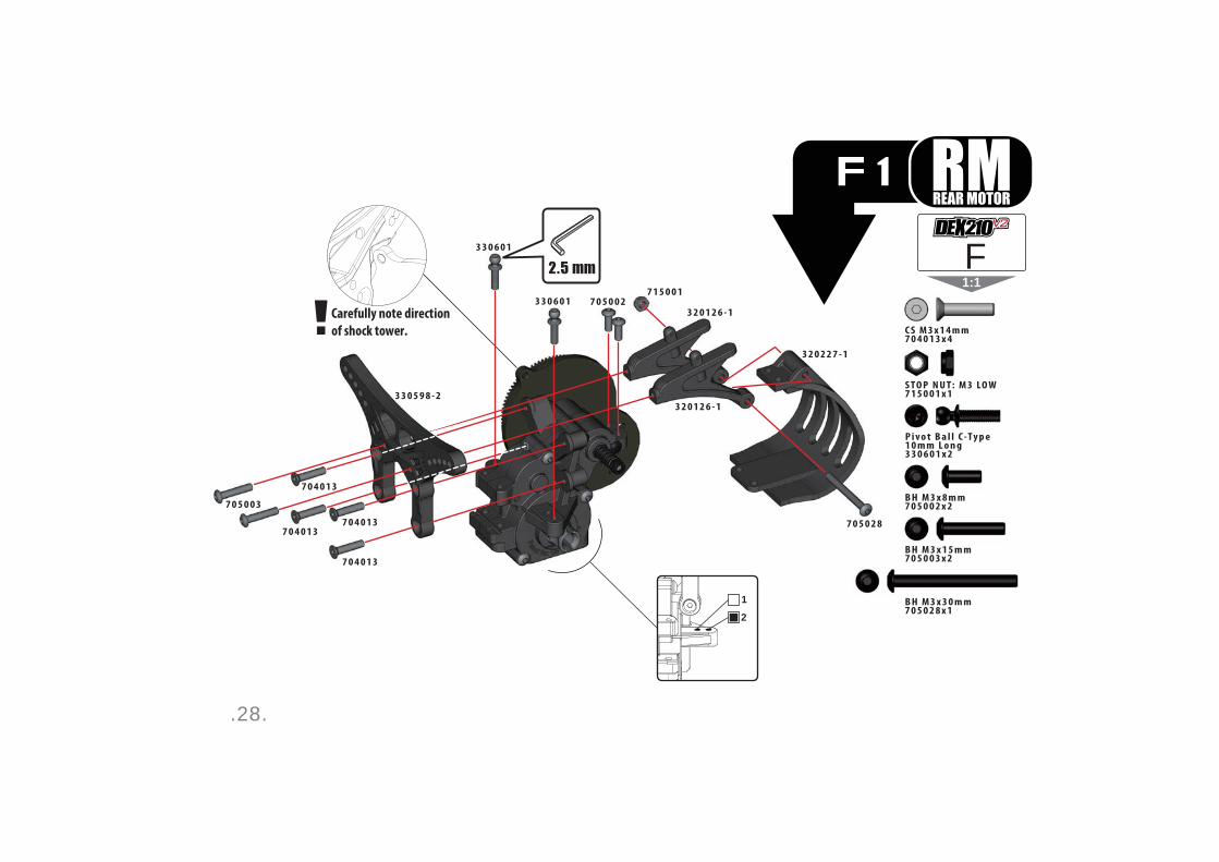
.28.
1:1
Carefully note direction
of shock tower.
1
2
S T O P N U T : M 3 LO W7 1 5 0 0 1 x 1
B H M 3 x 8 m m7 0 5 0 0 2 x 2
B H M 3 x 1 5 m m7 0 5 0 0 3 x 2
C S M 3 x 1 4 m m7 0 4 0 1 3 x 4
B H M 3 x 3 0 m m7 0 5 0 2 8 x 1
3 3 0 6 0 1
3 3 0 6 0 1
7 0 4 0 1 37 0 4 0 1 3
7 0 5 0 2 8
3 2 0 2 2 7 - 1
3 2 0 1 2 6 - 1
3 2 0 1 2 6 - 1
3 3 0 5 9 8 - 2
7 1 5 0 0 1
7 0 4 0 1 3
7 0 4 0 1 3
7 0 5 0 0 3
7 0 5 0 0 2
F
P i v o t B a l l C -Ty p e 1 0 m m L o n g3 3 0 6 0 1 x 2
F1
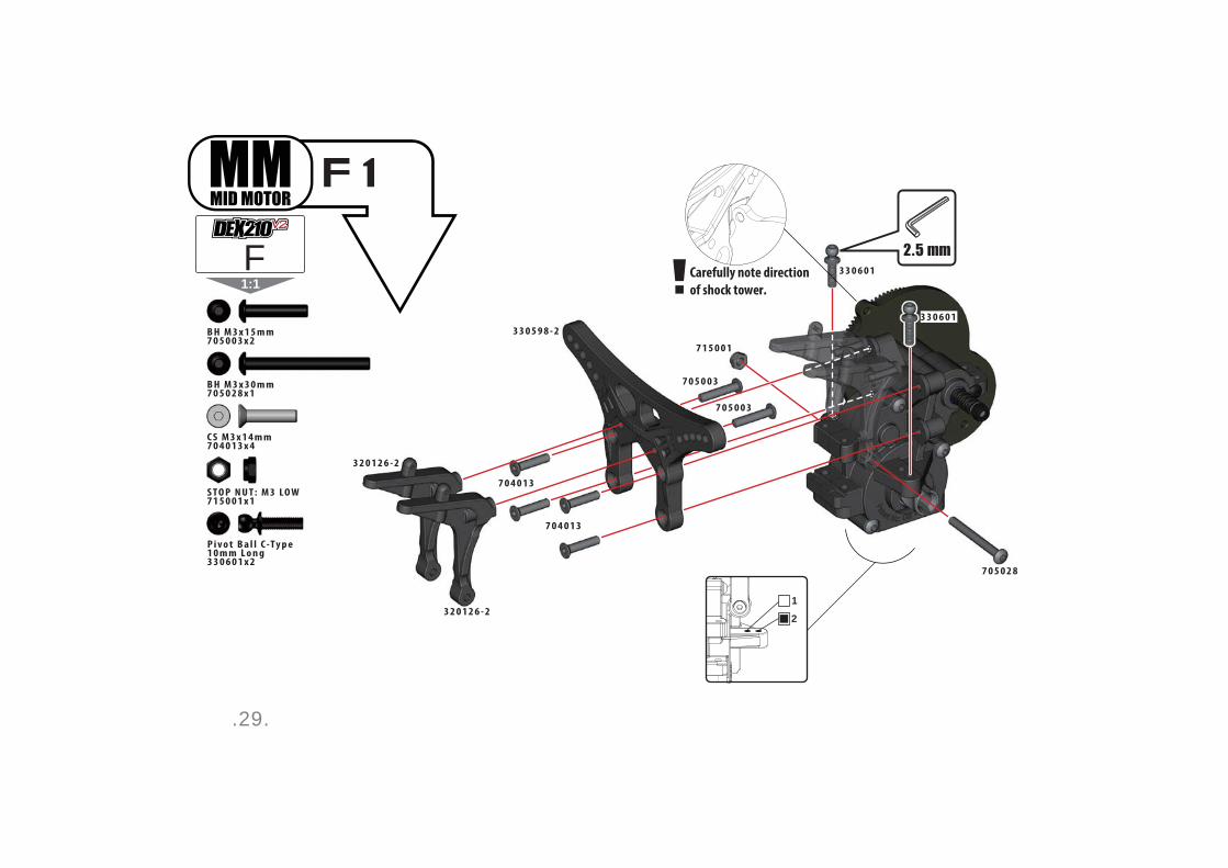
.29.
1:1Carefully note direction
of shock tower.
1
2
S T O P N U T : M 3 LO W7 1 5 0 0 1 x 1
B H M 3 x 1 5 m m7 0 5 0 0 3 x 2
B H M 3 x 3 0 m m7 0 5 0 2 8 x 1
C S M 3 x 1 4 m m7 0 4 0 1 3 x 4
3 3 0 6 0 1
3 3 0 6 0 1
7 0 4 0 1 3
7 0 4 0 1 3
7 0 5 0 2 8
3 2 0 1 2 6 - 2
3 2 0 1 2 6 - 2
3 3 0 5 9 8 - 2
7 1 5 0 0 1
7 0 5 0 0 3
7 0 5 0 0 3
F
P i v o t B a l l C -Ty p e 1 0 m m L o n g3 3 0 6 0 1 x 2
F1
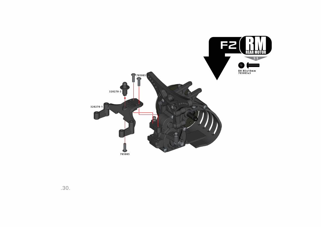
.30.
1:1
B H M 3 x 1 0 m m7 0 5 0 0 5 x 3
7 0 5 0 0 5
7 0 5 0 0 5
3 2 0 2 7 0 - 3
3 2 0 2 7 0 - 1
F2
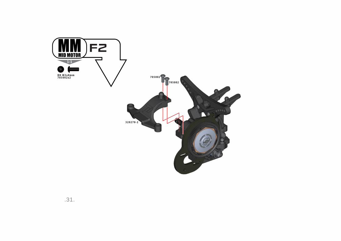
.31.
1:1
B H M 3 x 8 m m7 0 5 0 0 2 x 2
7 0 5 0 0 2
7 0 5 0 0 2
3 2 0 2 7 0 - 2
F2

.32.
1:1
8mm
C S M 3 x 1 0 m m7 0 4 0 0 7 x 2
C S M 3 x 8 m m7 0 4 0 0 6 x 2
B H M 3 x 1 0 m m7 0 5 0 0 5 x 4
S E T S C R E W M 3 x 1 6 m m7 0 1 0 0 8 x 2
B H M 3 x 1 2 m m7 0 5 0 0 4 x 4
7 0 4 0 0 7
7 0 4 0 0 7
7 0 1 0 0 8
7 0 1 0 0 8
7 0 4 0 0 6
7 0 4 0 0 6
7 0 5 0 0 4
7 0 5 0 0 4
7 0 5 0 0 5 7 0 5 0 0 4
7 0 5 0 0 5
7 0 5 0 0 5
7 0 5 0 0 5
7 0 5 0 0 4
3 2 0 1 2 8 - 1
3 2 0 2 7 0 - 5
3 2 0 2 7 0 - 5
3 2 0 2 6 9 - 1
F3

.33.
1:1
8mm
B H M 3 x 1 0 m m7 0 5 0 0 5 x 2
S E T S C R E W M 3 x 1 6 m m7 0 1 0 0 8 x 2
C S M 3 x 1 0 m m7 0 4 0 0 7 x 4
3 2 0 2 7 0 - 4
3 2 0 2 7 0 - 4
7 0 1 0 0 8
7 0 1 0 0 8
7 0 5 0 0 5
7 0 4 0 0 7
7 0 4 0 0 7
7 0 4 0 0 7
7 0 4 0 0 7
7 0 5 0 0 5
3 2 0 1 2 8 - 1
3 2 0 1 2 8 - 1
F3
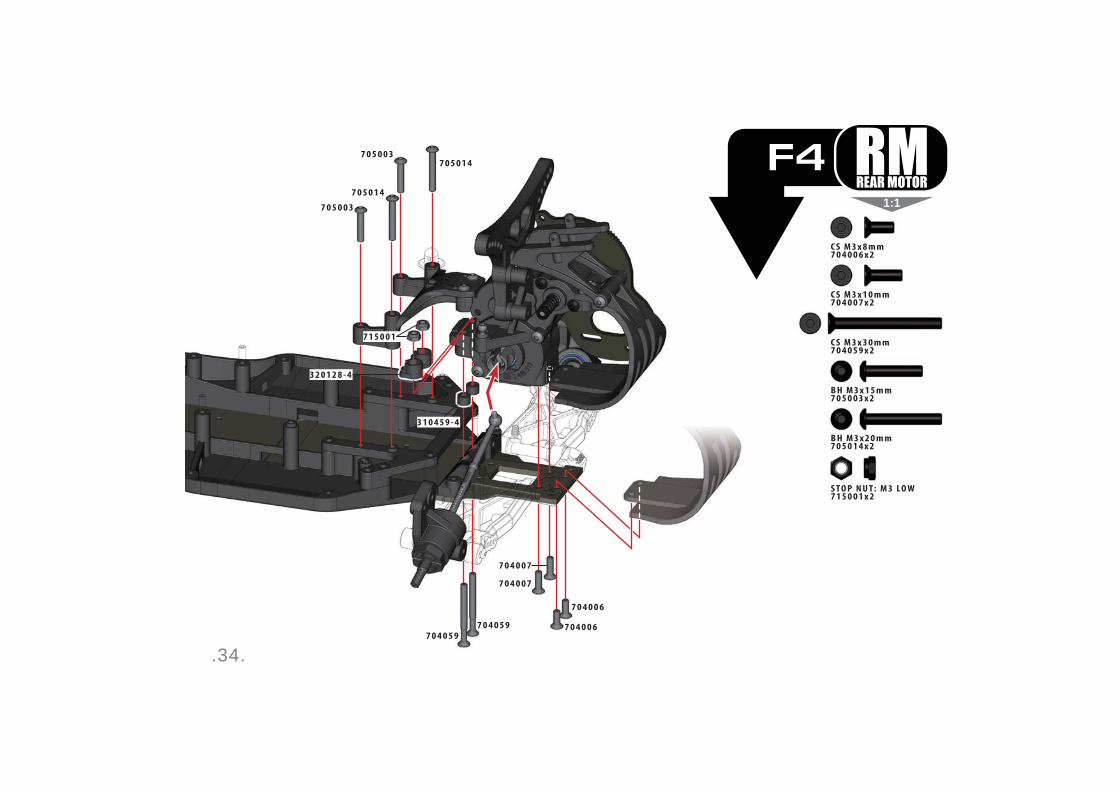
.34.
1:1
3 1 0 4 5 9 - 4
3 2 0 1 2 8 - 4
7 0 4 0 5 97 0 4 0 5 9
7 0 4 0 0 6
7 0 4 0 0 7
7 0 5 0 1 47 0 5 0 0 3
7 0 5 0 0 3
7 0 5 0 1 4
7 0 4 0 0 7
7 1 5 0 0 1
7 0 4 0 0 6
C S M 3 x 1 0 m m7 0 4 0 0 7 x 2
C S M 3 x 3 0 m m7 0 4 0 5 9 x 2
B H M 3 x 1 5 m m7 0 5 0 0 3 x 2
B H M 3 x 2 0 m m7 0 5 0 1 4 x 2
S T O P N U T : M 3 LO W7 1 5 0 0 1 x 2
C S M 3 x 8 m m7 0 4 0 0 6 x 2
F4
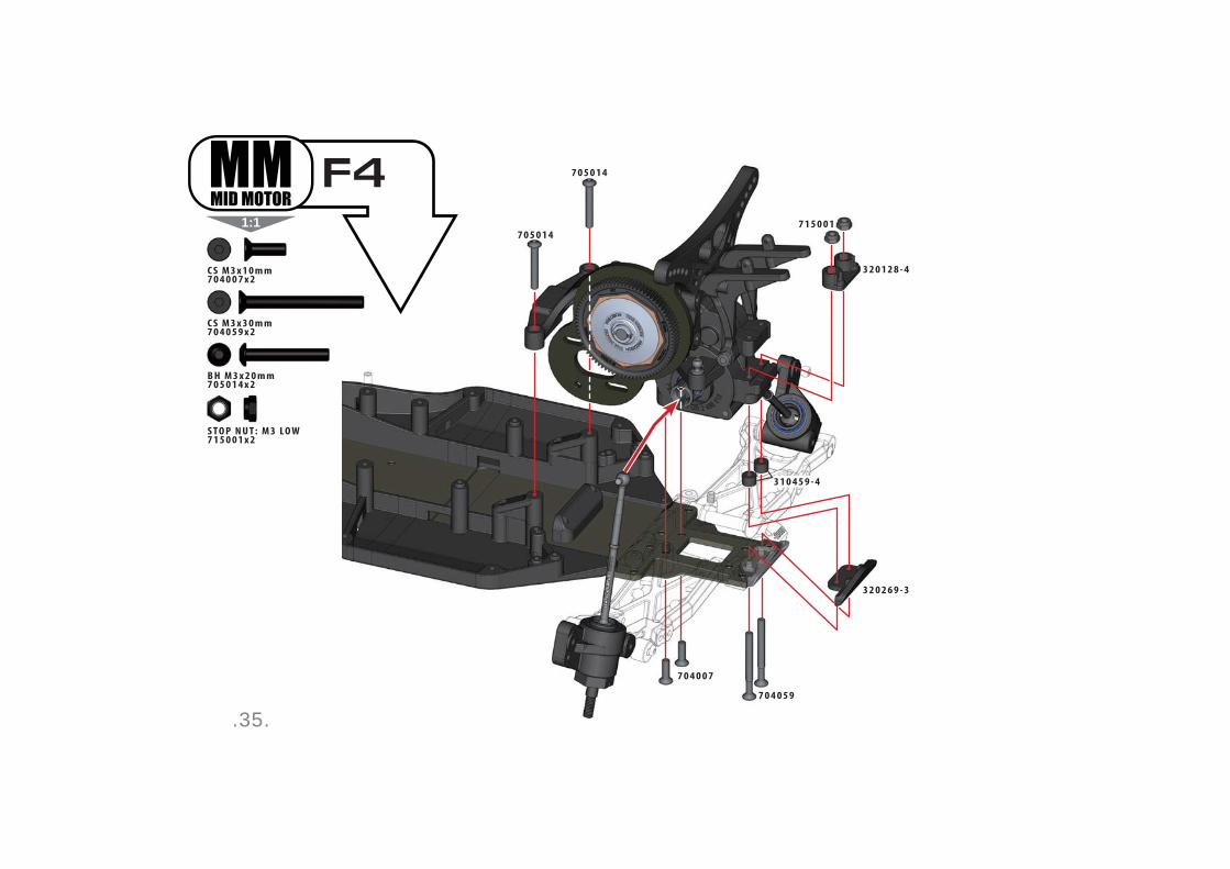
.35.
1:1
B H M 3 x 2 0 m m7 0 5 0 1 4 x 2
C S M 3 x 1 0 m m7 0 4 0 0 7 x 2
S T O P N U T : M 3 LO W7 1 5 0 0 1 x 2
C S M 3 x 3 0 m m7 0 4 0 5 9 x 2
3 2 0 2 6 9 - 3
3 2 0 1 2 8 - 4
7 0 5 0 1 4
7 0 5 0 1 4
7 1 5 0 0 1
7 0 4 0 5 9
7 0 4 0 0 7
3 1 0 4 5 9 - 4
F4

.36.
1:1
+
To achieve the optimum turnbuckle assembly, follow this step-by-step guide and you will build the perfect linkages. Prior to assembling your turnbuckle linkages, apply a small amount of silicone grease directly to the thread area of each turnbuckle linkage.
Step 1: Thread the ball cup onto the turnbuckle. Continue until all the turnbuckle linkage thread is inside the ball cup shaft.
Step 2: Unthread the ball cup from the turnbuckle completely. This will fully form the internal thread pattern inside your ball cup.
Step 3: Thread the ball cup onto the turnbuckle once again, and continue until you reach the
Step 4: Attach your assembled turnbuckle linkages
the supplied turnbuckle wrench.
1:11:1
1:11:1
1:11:1
1:1
2 0 m m
1 9 . 5 m m
1 9 . 5 m m
Front Left Camber Link
Front Right Camber Link
Rear Left Camber Link (MM)
Rear Right Camber Link (RM)
Rear Right Camber Link (MM)
Rear Left Camber Link (RM)
Steering Link (2 Pcs)
3 3 0 1 2 9
3 3 0 5 9 1 - 2 3 3 0 5 9 1 - 2
3 3 0 5 9 1 - 23 3 0 5 9 1 - 5 / 3 3 0 5 9 1 - 4 3 3 0 3 4 3G
G1
7 m m
7 m m
7 m m
7 m m
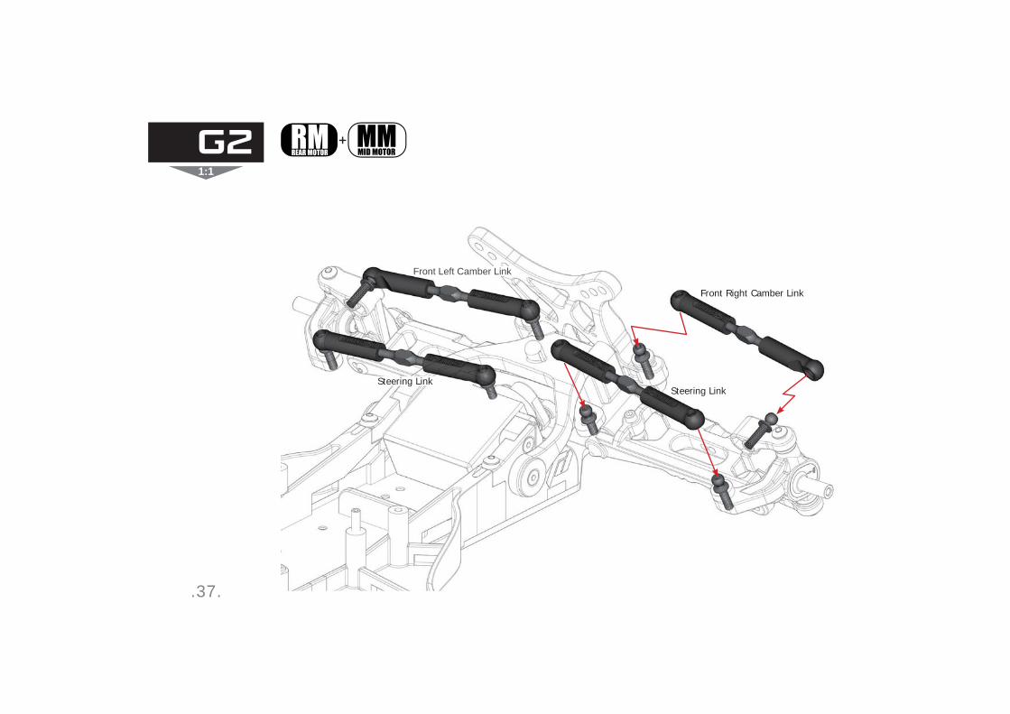
.37.
1:1
+
Front Left Camber Link
Front Right Camber Link
Steering LinkSteering Link
G2

.38.
1:1
Rear Right Camber Link (RM)
Rear Left Camber Link (RM)
G3
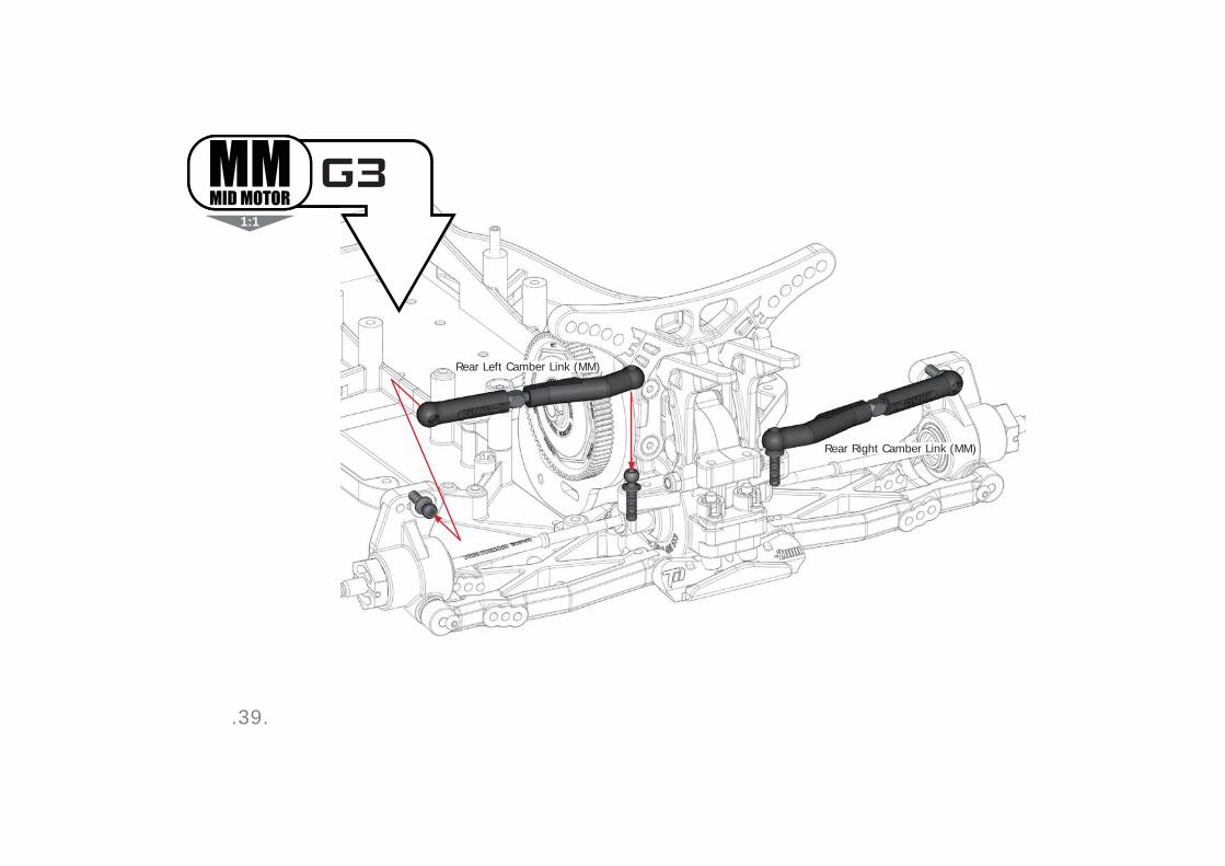
.39.
1:1
Rear Right Camber Link (MM)
Rear Left Camber Link (MM)
G3
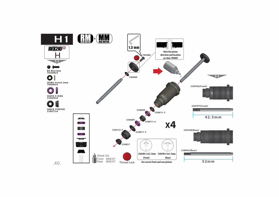
.40.
1:1
Note the piston
direction and location
on shim 709009
Thread Lock
+
Shock OILFront 400CSTRear 300CST
(Front) (Rear)
Use correct front and rear pistons
330590-3 2x1.7mm 330590-4 3x1.7mm
7 0 5 0 0 8
7 0 9 0 0 9
3 3 0 6 0 9
1:1
52mm
42.5mm
3 3 0 5 9 6 ( F r o n t )
3 3 0 1 6 9 ( R e a r )
3 3 0 5 9 7 ( F r o n t )
3 3 0 0 4 3 ( R e a r )
3 3 0 0 1 1 - 3
3 3 0 0 1 1 - 4
3 3 0 0 1 1 - 53 3 0 3 1 2 - 5
3 3 0 0 2 7
3 3 0 6 0 9
B H M 2 x 5 m m7 0 5 0 0 8 x 4
S H I M 2 . 6 x 5 x 0 . 5 m m7 0 9 0 0 9 x 4
S H O C K O - R I N G3 3 0 6 0 9 x 8
S H O C K S T O P P E R3 3 0 0 2 7 x 4
X4
H1
H
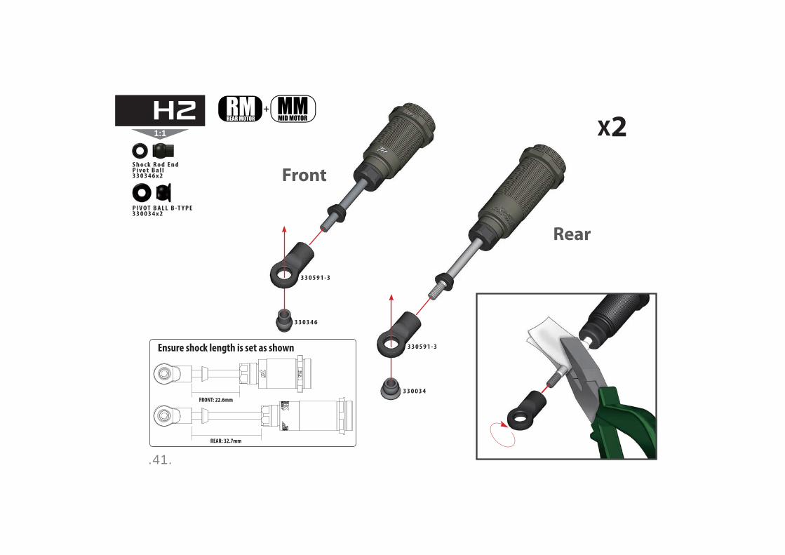
.41.
1:1 X2+
FRONT: 22.6mm
REAR: 32.7mm
Ensure shock length is set as shown
Rear
Front
3 3 0 5 9 1 - 3
3 3 0 3 4 6
3 3 0 0 3 4
3 3 0 5 9 1 - 3
P I V O T B A L L B -T Y P E3 3 0 0 3 4 x 2
S h o c k R o d E n d P i v o t B a l l3 3 0 3 4 6 x 2
H2

.42.
1:1
1
1
2
2
Shock OILFront 400CSTRear 300CST
M 2 X 57 0 5 0 0 8
1 3 X 13 3 0 1 6 0
3 3 0 6 0 0 - 1 ( F r o n t )3 3 0 6 0 0 - 2 ( R e a r )
3 3 0 3 1 2 - 1
3 3 0 1 8 1
+
Ensure the spring perch is
seated between the lower
ball and shock stopper
B H M 2 x 5 m m7 0 5 0 0 8 x 4
B B S H O C K C A P O - R I N G3 3 0 1 6 0 x 4
H3
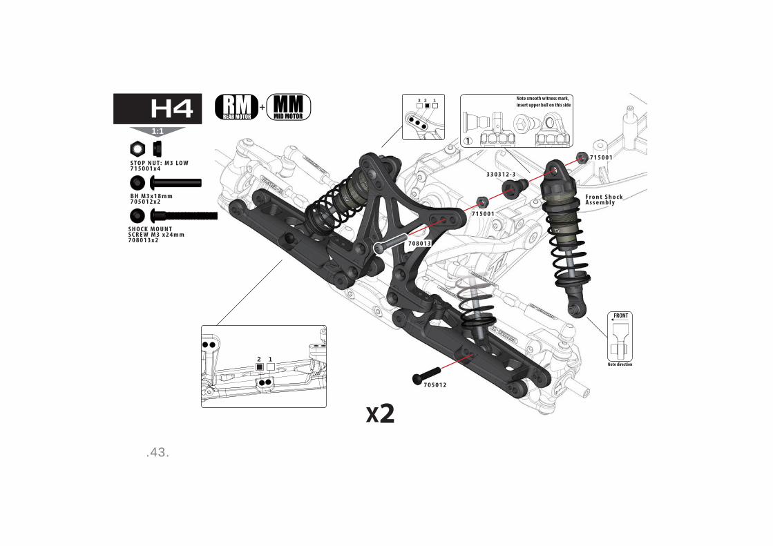
.43.
1:1
+
2 1
Press upper ball
into shock cap
FRONT
Note direction
13 2 Note smooth witness mark,
insert upper ball on this side
S T O P N U T : M 3 LO W7 1 5 0 0 1 x 4
B H M 3 x 1 8 m m7 0 5 0 1 2 x 2
S H O C K M O U N T S C R E W M 3 x 2 4 m m7 0 8 0 1 3 x 2
7 0 8 0 1 3
7 0 5 0 1 2
7 1 5 0 0 1
3 3 0 3 1 2 - 3
7 1 5 0 0 1
F r o n t S h o c k A s s e m b l y
X2
H4
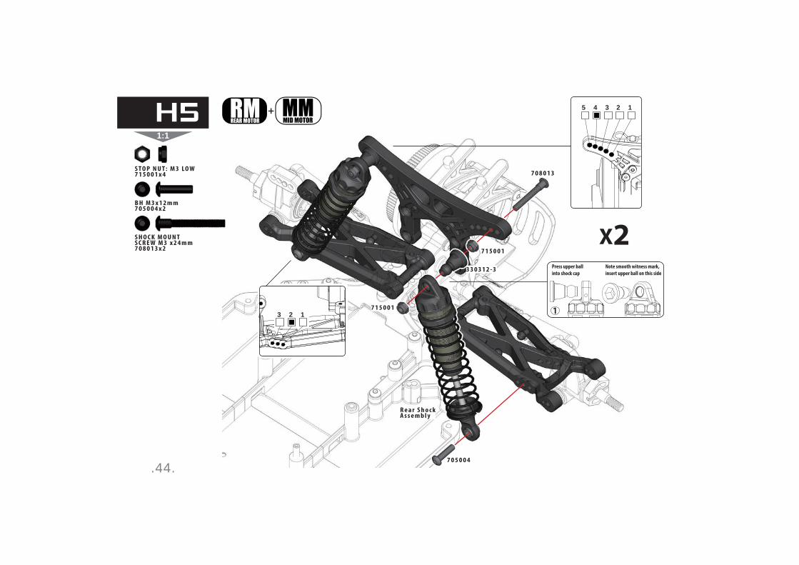
.44.
1:1
+
Note smooth witness mark,
insert upper ball on this side
Press upper ball
into shock cap
5 4 3 2 1
3 2 1
7 0 5 0 0 4
7 0 8 0 1 3
7 1 5 0 0 1
7 1 5 0 0 1
3 3 0 3 1 2 - 3
S T O P N U T : M 3 LO W7 1 5 0 0 1 x 4
B H M 3 x 1 2 m m7 0 5 0 0 4 x 2
S H O C K M O U N T S C R E W M 3 x 2 4 m m7 0 8 0 1 3 x 2
X2
R e a r S h o c k A s s e m b l y
H5
.45.
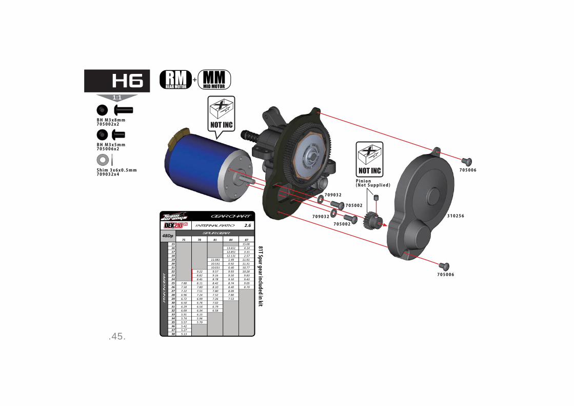
1:1
+
2.6
GEAR CHART
INTERNAL RATIO
SPUR GEAR
PIN
ION
GE
AR
75 78 81 84 87151617181920212223242526272829303132333435363738
15.0813.651 4.1412.851 3.3112.131 2.57
11.081 1.49 11.9110.531 0.92 11.3110.031 0.40 10.77
9.22 9.57 9.93 10.288.82 9.16 9.50 9.838.45 8.78 9.10 9.43
7.80 8.11 8.42 8.74 9.057.50 7.80 8.10 8.40 8.707.22 7.51 7.80 8.096.96 7.24 7.52 7.806.72 6.99 7.26 7.536.50 6.76 7.026.29 6.54 6.796.09 6.34 6.585.91 6.155.74 5.965.57 5.795.425.275.13
48Dp
81T Spur gear in
cluded in
kit
B H M 3 x 8 m m7 0 5 0 0 2 x 2
S h i m 3 x 6 x 0 . 5 m m 7 0 9 0 3 2 x 4
B H M 3 x 5 m m7 0 5 0 0 6 x 2
7 0 9 0 3 2
7 0 5 0 0 2
7 0 5 0 0 2
7 0 5 0 0 6
7 0 5 0 0 6
3 1 0 2 5 67 0 9 0 3 2
P i n i o n( N o t S u p p l i e d )
H6
.46.
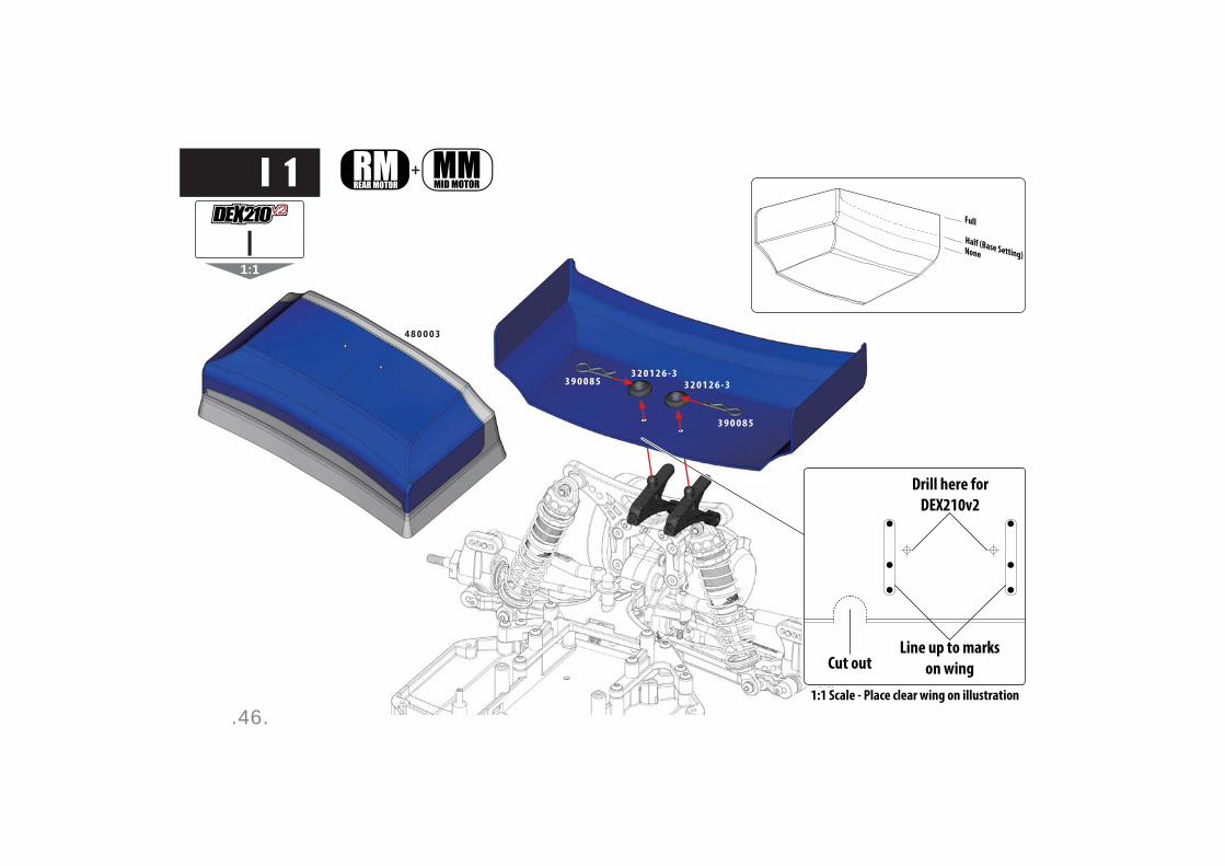
1:1
+
Full
Half (Base Setting)None
Drill here for
DEX210v2
Line up to marks
on wingCut out
1:1 Scale - Place clear wing on illustration
3 9 0 0 8 5
3 9 0 0 8 5
3 2 0 1 2 6 - 33 2 0 1 2 6 - 3
I1
I
4 8 0 0 0 3

.47.
1:1
+
3 9 0 2 9 8
3 2 0 1 2 8 - 2
3 2 0 1 2 8 - 3
3 2 0 1 2 8 - 3
I2

.48.
1:1
+
7 0 5 0 0 1
7 0 8 0 0 5
6 0 1 0 0 2
5 1 0 0 1 8
5 1 0 0 1 7
6 0 1 0 0 2
B H M 3 x 6 m m7 0 5 0 0 1 x 2
B B 5 x 1 0 x 4 m m6 0 1 0 0 2 x 4
N U T M 4 F L A N G E D R I F F L E D F L AT-S T Y L E7 0 8 0 0 5 x 2
X2
I3
.49.
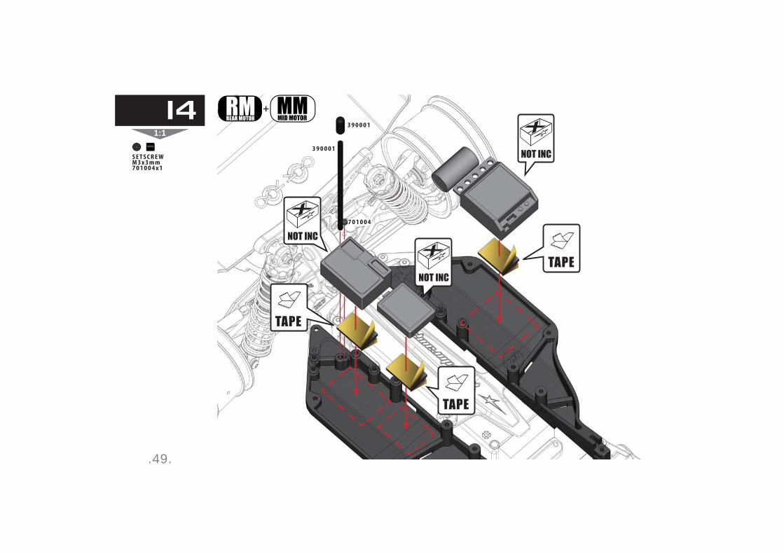
1:1
+
7 0 1 0 0 4
3 9 0 0 0 1
3 9 0 0 0 1
S E T S C R E W M 3 x 3 m m7 0 1 0 0 4 x 1
I4

.50.
1:1
3 9 0 0 8 5
4 0 2 0 3 1
3 9 0 0 8 5
I5Cut along cut line
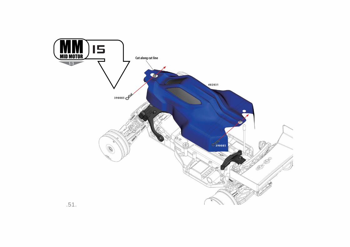
.51.
1:1
3 9 0 0 8 5
3 9 0 0 8 5
Cut along cut line
I5
4 0 2 0 3 1

.52.

.53.
.54.
.55.

.56.
Notes

.57.
Notes

.58.
Exploded View
.59.
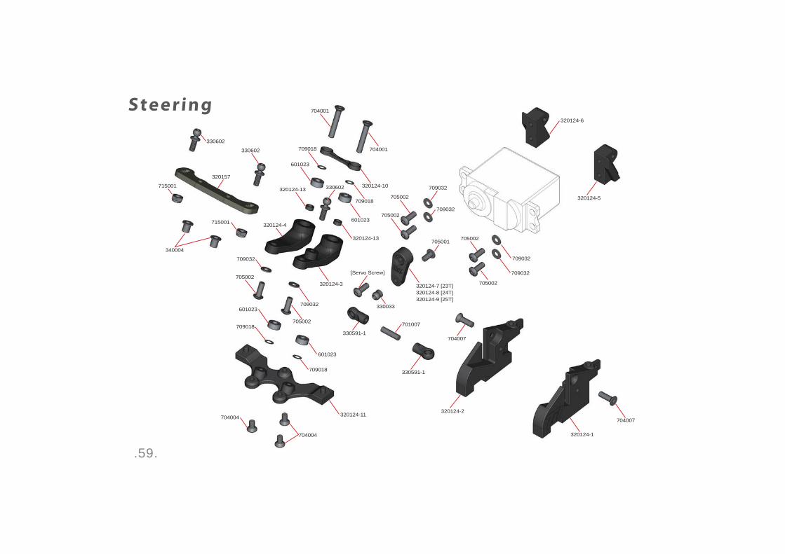
Steering
705001
320124-7 [23T]320124-8 [24T]320124-9 [25T]
709032
709032
320157
320124-2
320124-5
320124-6
709032
704007
320124-4
709018
704004
320124-13
601023
340004
701007
330591-1
330033
705002
705002
705002
705002
709018
601023
704001
704001
715001
705002
330602
330602
330602
330591-1
704007
320124-1
709032
709032[Servo Screw]
320124-10
709018
601023
320124-3
320124-13
601023
709018
320124-11
705002
704004
709032
715001

.60.
Front/Rear Hubs
310113310254
330312-2
330363-1
705005 330339-3
330363-2
330340-3
310437
330339-5
310123
601003
709015
709032
330363-1705004
340004
330340-10
330339-4
330363-1
330339-6
601017
330601
340004715001330339-1
330601
705004
330602
330340-8
310135
330339-2
715001 330349
R ight
Front
R ight
Rear
Lef t
Lef t
.61.
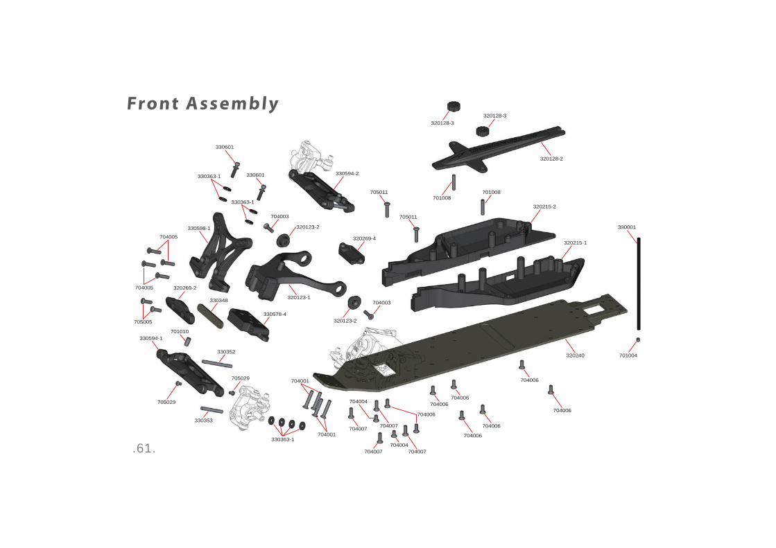
Front Assembly
330348
320215-2
320215-1
320128-3
704003
704003
330352
330594-2
320123-2
704007
705029
705029
320269-2
701004
390001
330353
701008
704004
704001
330578-4705005
704005
704005
701010
330598-1
330601
330601
320269-4
320123-2
705011
320128-2
705011
320128-3
330363-1
330363-1
704006
704006
704007
704007
704006
704006
704006
704006
704006
320240
701008
704004
704007704001
320123-1
330594-1
330363-1
.62.
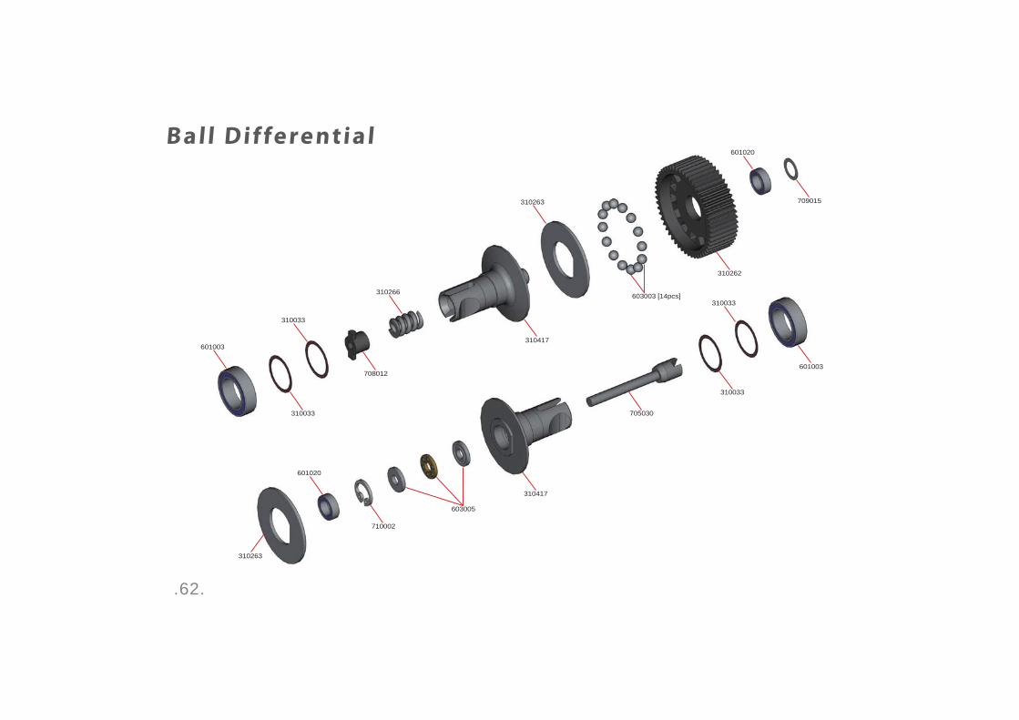
Ball Differential
310263
601020
310033
601020
310033
310263
601003
310266
603005
710002
310417
310033
601003
705030
709015
310262
310033
310417
603003 [14pcs]
708012
.63.
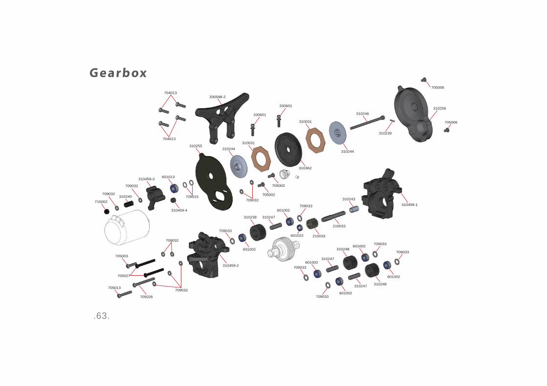
G earbox
310243709032
709032
601013
330598-2
705006
310246
310244
310031
310362
310031
310244
709032
310240715002
310459-3
310459-4
705006
310239
210033
310238
210033
310248
310248
601002
601002
601002
601022
310247
310247
310247
601002
601002
601002
709032709015 705002
705002
705027
310459-2
704013
704013
310255
330601
330601
709033
709033
709033
709033
709033
709033
705013
705026
705003
310256
310459-1
709032
.64.
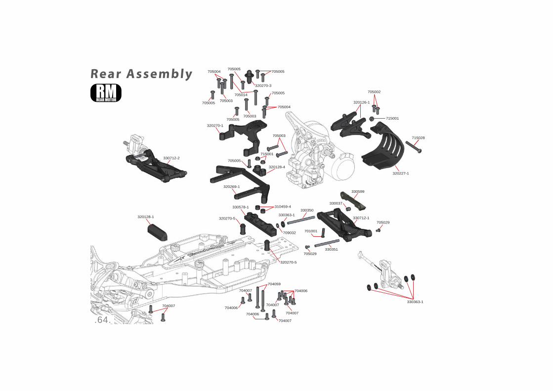
Rear Assembly
320126-1
705003
715001
715001
320269-1
320270-1
320128-1
320128-4
330350
330037
705029
330351705029
330578-1
320270-5330363-1
320270-5
709032
310459-4
330599
330712-1
330712-2
701001
705005
705003
705003
705004
705004
705014
705005
705005
705005
705005
705005
320270-3
704007
704006
704006
704006
704007
704007
704007
704007
704059
705002
715028
320227-1
330363-1

.65.
Rear Assembly320126-2
705028
715001
320128-4
330037
330363-1
320128-1
320128-1 330350709032
330363-1
330351
705029
705029
310459-4
330599
330578-1
320269-3
320270-4
320270-4
320270-2
705014
705014
705005
705005
705002
705003
701001
704007704007
704006
704006
704007
704007 704059
330712-1
330712-2
.66.
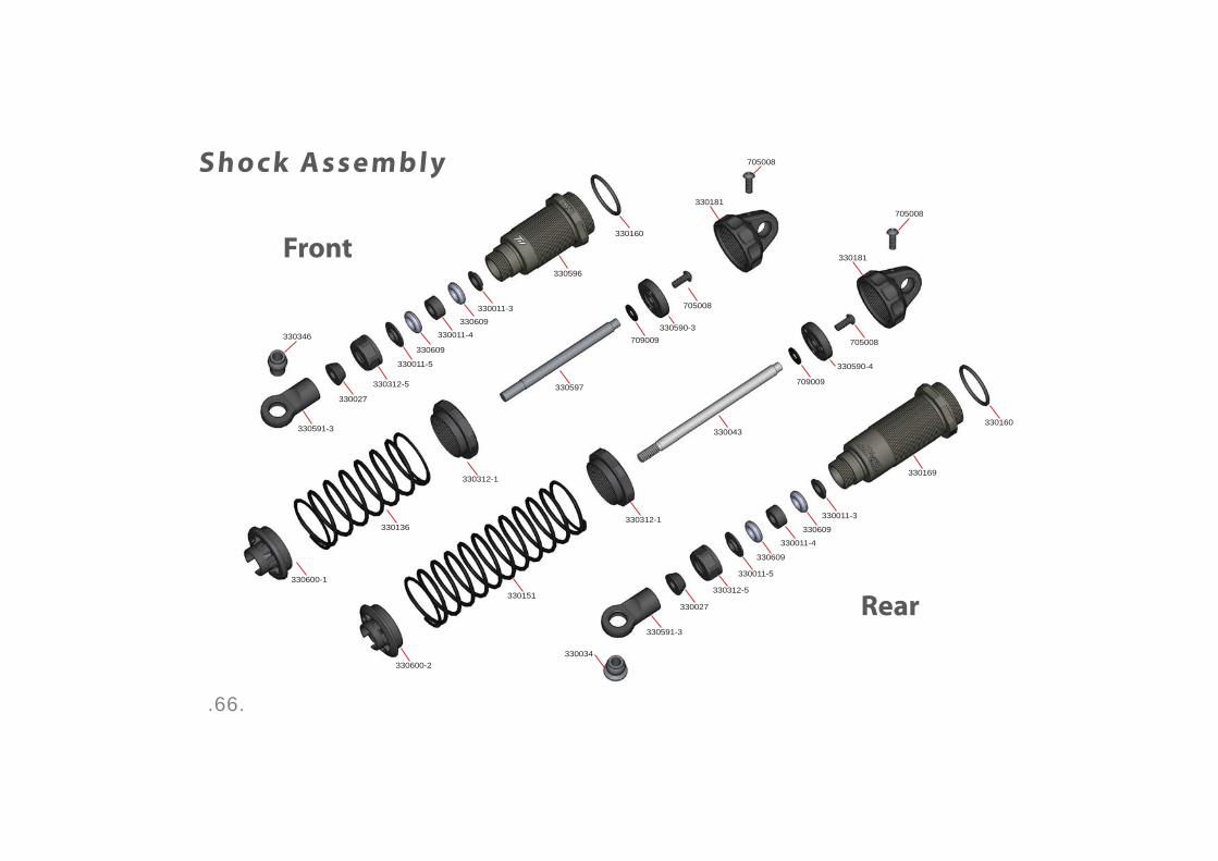
Shock Assembly
Rear
Front
330169
330596
330160
330160
705008
705008
709009
709009
330043
330597
330312-1
330312-1
330600-2
330600-1
330136
330151
330590-4
330590-3
330011-3
330181
330181
330609
330609
330011-4
330011-5
330312-5
330027
330591-3
330591-3
330034
330346
705008
705008
330011-3
330609
330609
330011-4
330011-5
330312-5
330027
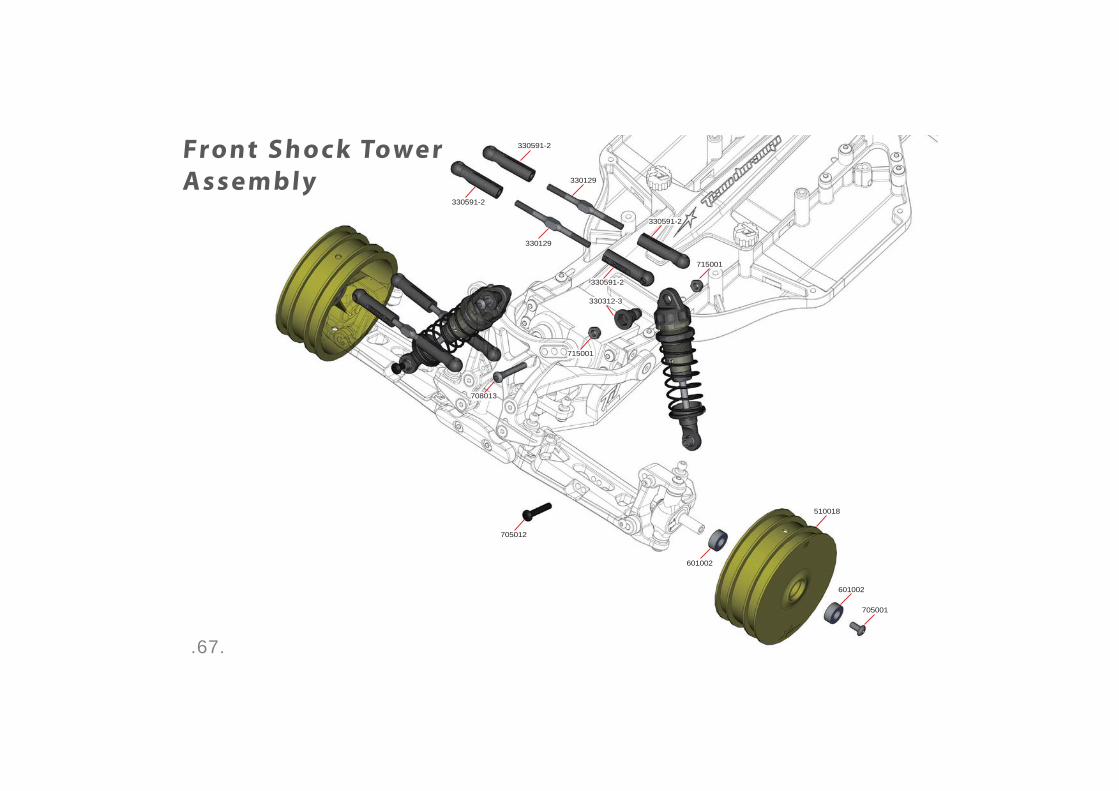
.67.
708013
715001
715001
330591-2
330591-2
Front Shock Tower
Assembly
330312-3
330591-2
330591-2
330129
330129
705012
601002
601002
510018
705001
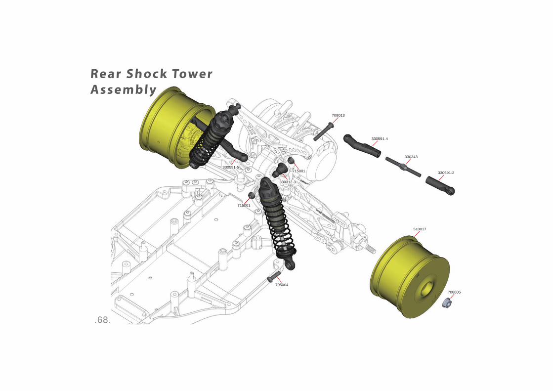
.68.
715001
Rear Shock Tower
Assembly
330343
330591-2715001
708005
330591-4
330591-5
708013
705004
330312-3
510017
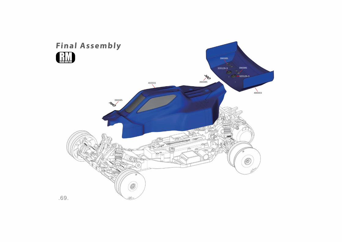
.69.
Final Assembly
390085
402031
480003
390085
390085
320126-3
320126-3
390085
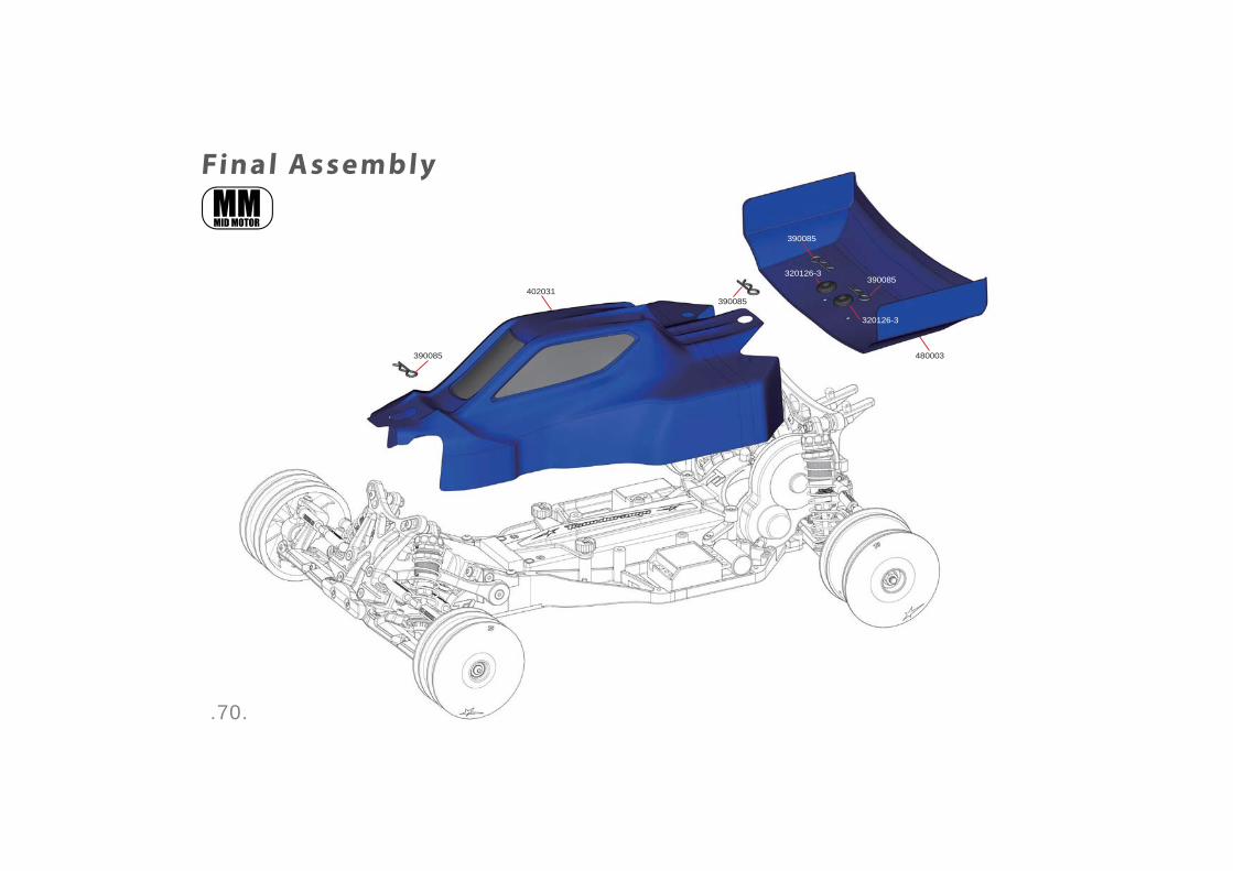
.70.
Final Assembly
390085
390085
390085
320126-3
320126-3
390085402031
480003

.71.
TD210033 LAYSHAFT SETTD220005 BALL DIFF SETTD310031 SLIPPER CLUTCH PAD (2pcs)
TD310238 IDLER GEAR SET
TD310244 SLIPPER HUB SET (1pr)TD310246 SLIPPER SHAFT
TD310254 REAR AXLE (2pcs)
TD310256 GEAR COVER
TD310263 BALL DIFF PLATES (2pcs)TD310264 BALL DIFF OUTDRIVES (LIGHTWEIGHT - SHORT) (1pr)
TD310362 SPUR GEAR 81T (48DP)
TD310459 GEARBOX SET (TYPE B)
TD320215 CHASSIS SIDE POD SET (+8mm)TD320227 MOTOR GUARD (Type B)
TD320269 BUMPER & REAR TOP DECK SET (TYPE B)TD320270 REAR CHASSIS BRACE SET (Type B)
TD330027 SHOCK STOPPER: RUBBER (4pcs)TD330033 PIVOT BALL A-TYPE (4pcs)TD330034 PIVOT BALL B-TYPE (4pcs)
Parts# Description TD330169 BIG BORE SHOCK BODY: 31mm STROKE (1pc)TD330181 BIG BORE SHOCK CAP (4pcs)TD330312
TD330363 PLASTIC SPACER SET
TD330596 BIG BORE SHOCK BODY: 21.5mm STROKE (1pc)
TD330598 SHOCK TOWER SET (TYPE B)
TD330601 2mm HEX BALL M3x10mm (4pcs)TD330602 2mm HEX BALL M3x7mm (4pcs)
TD510017 WHEEL RIM REAR: 14mm HEX YELLOW (2pcs)
TD603003 3mm DIFF BALLS (14pcs)
Parts# DescriptionPar ts List- Standard Par ts
.72.
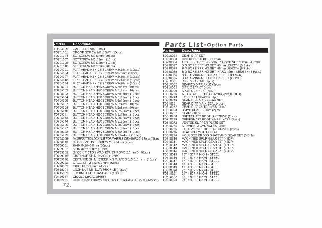
TD603005 CAGED THRUST RACETD701001 DROOP SCREW M3x13MM (10pcs)TD701004 SETSCREW M3x3mm (10pcs)TD701007 SETSCREW M3x12mm (10pcs)TD701008 SETSCREW M3x16mm (10pcs)TD701010 SETSCREW M4x8mm (10pcs)TD704001 FLAT HEAD HEX CS SCREW M3x18mm (10pcs)TD704004 FLAT HEAD HEX CS SCREW M3x6mm (10pcs)TD704007 FLAT HEAD HEX CS SCREW M3x10mm (10pcs)TD704013 FLAT HEAD HEX CS SCREW M3x14mm (10pcs)TD704054 FLAT HEAD HEX CS SCREW M3x30mm (10pcs)
TD708005
TD709001 SHIM 5x10x0.8mm (10pcs)TD709002 SHIM 4x8x0.3mm (10pcs)
TD709032 STEEL SHIM 6x3x0.5mm (20pcs)TD710002 CIRCLIP 8x0.8mm (4pcs)
TD490037 DEX210 DECAL SHEETTD402031 DEX210 CAB FORWARD BODY SET (Includes DECALS & MASKS)
Parts# Description
Parts# DescriptionPar ts List- Option Par ts
TD210034 GEAR DIFF SETTD210038 CVD REBUILD KIT (2.Omm)TD230004 1/10 ELECTRIC BIG BORE SHOCK SET: 23mm STROKE
TD310001 DIFF. GEAR 14T (2pcs)TD310002 GEARED DIFF. AXLE (2pcs)TD310003 DIFF. GEAR 9T (4pcs)TD310020 SPUR GEAR 87T (48DP)TD310226 ALLOY WHEEL HEX (14mm)(2pcs)(GOLD)TD310243 LAYSHAFT SPACER (1pc)
TD310252 GEAR DIFF OUTDRIVES (2pcs)TD310253 DRIVE SHAFT 65mm (2pcs)TD310257 GEARBOX SETTD310258 DRIVESHAFT BOOT OUTDRIVE (2pcs)TD310259 DRIVESHAFT BOOT WHEEL AXLE (2pcs)
TD310275 LIGHTWEIGHT DIFF OUTDRIVES (2pcs)

.73.
Parts# Description
TD310395 ALLOY WHEEL HEX (14mm)(2pcs)(BLACK)TD310396 ALLOY WHEEL HEX (14mm)(2pcs)(RED)TD310397 ALLOY WHEEL HEX (14mm)(2pcs)(OLIVE)
TD320121 BUMPER & REAR TOP DECK SETTD320122 CHASSIS SIDE POD SET
TD320127 REAR CHASSIS BRACE SETTD320129 REAR BUMPER (REAR MOTOR)
TD320162 SERVO SAVER SET (10th SCALE)TD320163 DIMEC DEX210 CHASSIS (+8mm)
TD320220 DIMEC20 CHASSIS DEX210 (+8mm)TD320229 DIMEC CHASSIS DEX210 (+8mm) (Type B)TD320247 DIMEC20 CHASSIS DEX210 (+8mm) (Type B)TD330017 SHOCK BOOT: REAR (2pcs)
TD330035 PIVOT BALL C-TYPE (4pcs)
TD330154 BIG BORE SHOCK BODY: 23mm STROKE (1pc)
Parts# Description

.74.
Parts# Description
TD330282
TD330285
TD330342 SHOCK TOWER SET
TD330345 SHOCK SHAFT: REAR (55mm 2pcs)TD330347 PIVOT BALL C-TYPE 10mm (4pcs)
TD330400 DEX210 Imperial Steel Front Axle (Pair)TD330453 TD330454 TD330455 TD330456 TD330457 TD330458 TD330459 TD330460 TD330461 TD330462 TD330463 TD330464 TD330465 TD330466 TD330467 TD330468 TD330554 TD330555
TD330556
TD330576 PIVOT BALL (3.5*6mm 4pcs)TD330577 PIVOT BALL (3*6mm 4pcs)
TD390003 BODY CLIP SMALL (10pcs)TD390026 TD402012 DEX210 CAB FORWARD BODY (+8mm) (Includes DECALS & MASKS)TD490020 DEX210 DECAL SHEETTD510015 WHEEL RIM REAR: 14mm HEX WHITE (2pcs)
TD704008 FLAT HEAD HEX CS SCREW M2x10mm (10pcs)
TD709058 SHIM 3.5x8x0.5mm (4pcs) (BLACK)TD709059 PVC WASHER (2.1*3.5*0.2mm 16pcs) (GREY)TD710001 E-CLIPS FOR DIFF 4mm ID (10pcs)
Parts# Description

.75.
Team Durango Ltd
Team Durango
Team Durango Ltd is registered in Derbyshire, England, UK
Internet:
www.team-durango.com
The contents of this owner’s manual and all associated
material are copyright © Team Durango Ltd. No part of this
owner’s manual or associated material may be reproduced
or distributed in any medium or media without the express,
written permission of Team Durango Ltd.
Team Durango Ltd is in Derbyshire, England, Großbritannien registriert
Internet: www.team-durango.com [email protected]
Der Inhalt dieser Bauanleitung und alles dazugehörige Material unterstehen dem Copyright Team Durango Ltd.Kein Teil dieser Bauanleitung, oder dazugehöriges Material darf weder kopiert, oder in jegliches Medium vertrieben werden, ohne die schriftliche Zustimmung von Team Durango Ltd.
Team Durango Derbyshire, England, UK
www.team-durango.com
Team Durango
Team Durango
Team Durango Ltd Derbyshire, England, UK
www.team-durango.com
Team Durango Ltd
Team Durango Ltd
Team Durango Ltd

請使用封面資料夾中的檔案DEX210 V2_Manual_Cover_Back_Final_Outl ined.ai