Embed Size (px)
Citation preview

Dichiarazione CE di conformità
EC declaration of conformity
Torino, 04/03/2015
REER SpA
via Carcano 32
10153 – Torino
Italy
dichiara che le barriere fotoelettriche VISION VXL / VISION MXL sono Dispositivi Elettrosensibili di
Sicurezza (ESPE) di : Tipo 2 (secondo la Norma IEC 61496-1(ed.3); IEC 61496-2(ed.3))
SILCL 1 (secondo la Norma EN 62061(ed.1))
PL c (secondo la Norma EN ISO 13849-1:2008)
declares that the VISION VXL / VISION MXL photoelectric safety barriers are : Type 2 (according the Standard IEC 61496-1(ed.3); IEC 61496-2(ed.3))
SILCL 1 (according the Standard EN 62061(ed.1))
PL c (according the Standard EN ISO 13849-1:2008)
Electro-sensitive Protective Equipments (ESPE)
realizzati in conformità alle seguenti Direttive Europee:
complying with the following European Directives:
2006/42/CE "Direttiva Macchine"
"Machine Directive"
2004/108/CE "Direttiva Compatibilità Elettromagnetica"
"Electromagnetic Compatibility Directive"
2006/95/CE "Direttiva Bassa Tensione"
"Low Voltage Directive"
e sono identiche all'esemplare esaminato ed approvato con esame di tipo CE da:
and are identical to the specimen examined and approved with a CE - type approval by:
TÜV SÜD Rail GmbH – Ridlerstrasse 65 – D-80339 – Muenchen – Germany
Carlo Pautasso Simone Scaravelli
Direttore Tecnico Amministratore Delegato
Technical Director Managing director
8540687 • 04/03/2015 • Rev.13 1
PHOTOELECTRIC
SAFETY LIGHT CURTAIN
VISION MXL
INSTALLATION USE AND MAINTENANCE
SUMMARY
INTRODUCTION ........................................................................................................................... 2 NEW SAFETY PARAMETERS FOR TYPE 2 BARRIERS AND MANDATORY LABELLING ............ 3
OPERATION ................................................................................................................................. 4 INSTALLATION ............................................................................................................................. 5
MUTING FUNCTION........................................................................................................................... 6 POSITIONING ................................................................................................................................... 10 SAFETY DISTANCE CALCULATION ............................................................................................... 11 VERTICAL POSITION OF THE LIGHT CURTAIN ........................................................................... 12 MULTIPLE SYSTEMS....................................................................................................................... 13 DISTANCE BETWEEN REFLECTING SURFACES ......................................................................... 13 MECHANICAL ASSEMBLY AND OPTICAL ALIGNMENT ............................................................... 15 ELECTRICAL CONNECTIONS ........................................................................................................ 16 EMITTER CONNECTIONS ............................................................................................................... 16 RECEIVER CONNECTIONS ............................................................................................................ 17 WARNINGS REGARDING THE CONNECTION CABLES ............................................................... 17 CONFIGURATION AND MODE OF OPERATIONS ......................................................................... 19
OPERATION AND TECHNICAL DATA ....................................................................................... 24 SIGNALS ........................................................................................................................................... 24 TEST FUNCTION .............................................................................................................................. 25 MUTING LAMP ................................................................................................................................. 25 MUTING ENABLE COMMAND ......................................................................................................... 25 OUTPUT STATUS ............................................................................................................................ 26 TECHNICAL SPECIFICATIONS ....................................................................................................... 27
DIMENSIONS (mm) .................................................................................................................... 29 CHECKOUTS AND MAINTENANCE .......................................................................................... 32
VERIFICATION OF LIGHT CURTAIN EFFICIENCY ........................................................................ 32 TROUBLESHOOTING ...................................................................................................................... 33
SPARE PARTS ........................................................................................................................... 35 GUARANTEE .............................................................................................................................. 36
VISION MXL
2 8540687 • 04/03/2015 • Rev.13
This symbol stands by a very important warning concerning the safety of persons. Its non-observance can cause a very serious risk for the exposed personnel.
INTRODUCTION VISION MXL light curtain is a multibeam optical-electronic safety system belonging to the category of Type 2 electro-sensitive devices, and is equipped with a MUTING function to protect people exposed to dangerous machines or equipment, according to norms IEC 61496-1,2 and EN 61496-1. VISION MXL is composed of Emitter plus Receiver, with added functions such as Muting, feedback control of eventual external contactors, and manual/automatic function management. A series of warning LEDs located on the Emitter and the Receiver display the information necessary for the correct use of the device and to evaluate eventual functioning anomalies. Thanks to an automatic self-monitoring system, VISION MXL light curtain is able to autonomously detect any dangerous fault in a maximum of 0,5 seconds. This detection system is permanently active and does not need any external command. VISION MXL is ideal for protecting:
automatic palletizing/depalletizing systems materials handling and storage systems; packing and packaging machines; assembly lines; industrial automatic warehouses; AGV transit openings; metal, wood, marble and glass tool machines.
Carefully consider the risk analysis of the application and the legislation of the light curtain application within the Country to establish if the application is compatible with the safety category 2.
If necessary, for any safety-related problems contact the competent safety authorities or industrial associations in the country of use.
For applications in the food industry, please contact ReeR to ensure that the light curtain contains materials that are compatible with the chemical agents utilized.
The protective function of the optoelectronic devices is not effective in the following case:
If the machine stopping control cannot be actuated electrically and it is not possible to stop all dangerous machine movements immediately and at any time during the operating cycle.
If the machine generates dangerous situations due to material being expelled or falling from overhead.

VISION MXL
8540687 • 04/03/2015 • Rev.13 3
NEW SAFETY PARAMETERS FOR TYPE 2 BARRIERS AND MANDATORY LABELLING
With the publication of Edition 3 of the harmonized EN 61496-1 standard it is no longer possible to use a Type 2 safety light barrier for safety functions assessed as SIL 2 / PL d.
If a safety level of SIL 2 / PL d (or higher) is required and it is nevertheless intended to use a safety light barrier, then it will be necessary to use a Type 4 safety light barrier.
This regulatory requirement derives from the fact that the reduction of risk that can be obtained via a photoelectric safety barrier is not only a function of the safety level of its electronic parts, but is also determined by its systematic capabilities (for example: environmental influences, EMC, optical performance and detection principle).
The systematic capability of a Type 2 photoelectric barrier may in fact not be sufficient to ensure adequate risk reduction for SIL 2 / PL d applications.
The standard also establishes that the labelling of Type 2 safety barriers must indicate such limitation to SIL 1 / PL c.
The PFHd values declared for the electronic control part of the device, on the other hand, are not limited and therefore it is possible to use the PFHd value provided by the manufacturer of the device in the global assessment of the safety function, even if it exceeds the SIL 1 / PLc range.

VISION MXL
4 8540687 • 04/03/2015 • Rev.13
OPERATION
If the protected area is clear, the two outputs on the Receiver are active and enable the machine to which they are connected to operate normally. Each time that an object bigger than or equal in size to the resolution of the system intercepts the optical path of one or more beams, the Receiver deactivates the outputs. This condition enables hazardous machine movements to be stopped (by means of an adequate machine emergency stop circuit).
The resolution is the minimum dimensions that an object must have so that, on crossing the protected area, it will certainly intercept at least one of the optical beams generated by the light curtain (Figure 1).
Figure 1
The resolution is constant irrespectively of work conditions, as it only depends on the geometric characteristics of the lenses and the distance between the centres of two adjacent lenses. The height of the protected area is the height that is actually protected by the safety light curtain. If the latter is placed horizontally, this value refers to the depth of the protected area. The working range is the maximum operative distance that can exist between the Emitter and the Receiver. VISION MXL is available with the following resolutions:
– 30 mm (protected height from 150 mm to 1200 mm) PROTECTION OF HANDS
– 40 mm (protected height from 300 mm to 1200 mm) PROTECTION OF HANDS
VISION MXL is available also in the 2, 3, 4 beams configuration with the following lens pitch:
– 500mm (2 beams), 400mm (3 beams), 300mm (4 beams). PROTECTION OF BODY
P = Pitch between two lenses D = Diameter of one lens R = Resolution = P+D
VISION MXL
8540687 • 04/03/2015 • Rev.13 5
INSTALLATION Before installing the VISION MXL safety system, make sure that:
The safety system is only used as a stopping device and not as a machine control device.
The machine control can be actuated electrically.
All dangerous machine movements can be interrupted immediately. In particular, the machine stopping times must be known and, if necessary, measured.
The machine does not generate dangerous situations due to materials projecting or falling from overhead; if that is not the case, additional mechanical guards must be installed.
The minimum dimensions of the object that must be detected are greater than or equal to the resolution of the specific model.
Knowledge of the shape and dimensions of the dangerous area enables the width and height of the relative access area to be calculated.
Compare these dimensions with the maximum working range and the height of the protected area in relation to the specific model.
The general instructions set out below must be taken into consideration before placing the safety device in position.
Make sure that the temperature of the environment in which the system is to be installed is compatible with the temperature parameters contained in the technical data sheet.
Do not install the Emitter and Receiver close to bright or high-intensity flashing light sources.
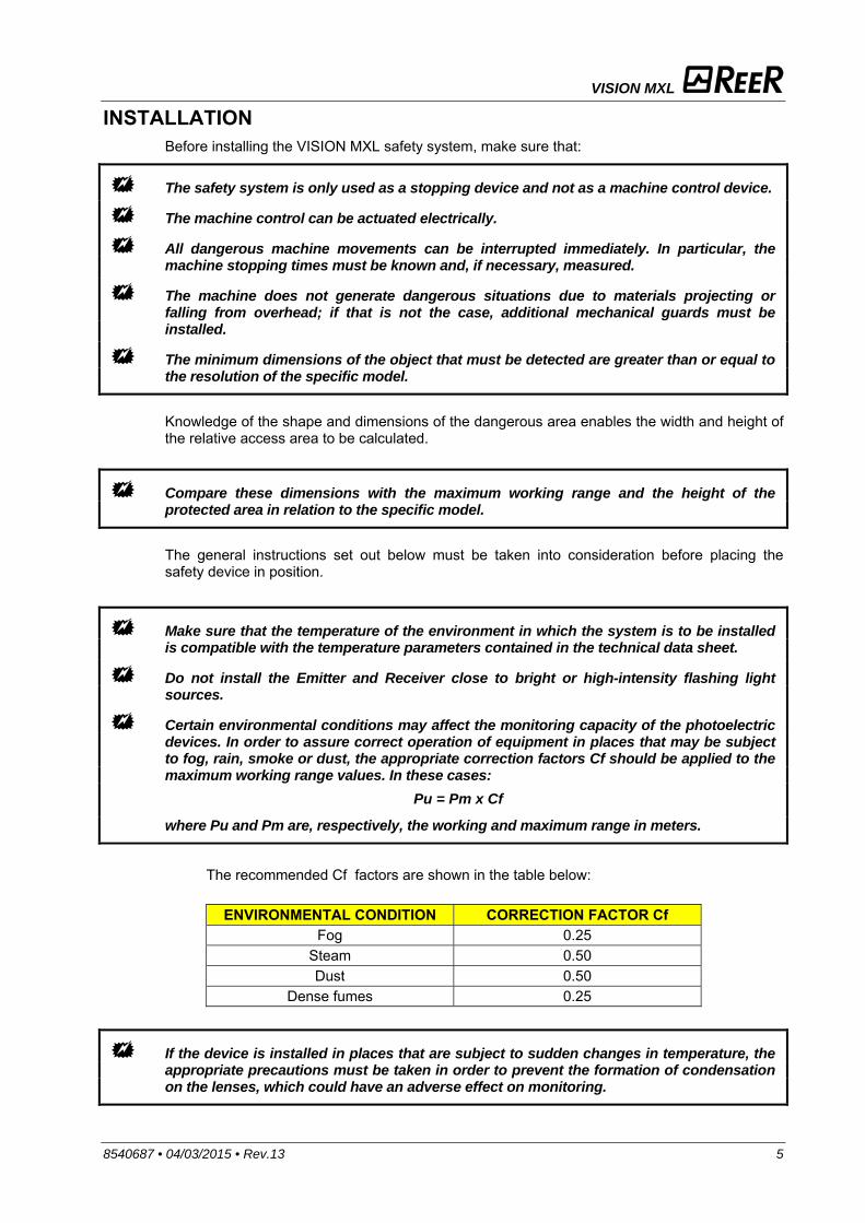
Certain environmental conditions may affect the monitoring capacity of the photoelectric devices. In order to assure correct operation of equipment in places that may be subject to fog, rain, smoke or dust, the appropriate correction factors Cf should be applied to the maximum working range values. In these cases: where Pu and Pm are, respectively, the working and maximum range in meters.
The recommended Cf factors are shown in the table below:
ENVIRONMENTAL CONDITION CORRECTION FACTOR Cf Fog 0.25
Steam 0.50 Dust 0.50
Dense fumes 0.25
If the device is installed in places that are subject to sudden changes in temperature, the appropriate precautions must be taken in order to prevent the formation of condensation on the lenses, which could have an adverse effect on monitoring.
Pu = Pm x Cf
VISION MXL
6 8540687 • 04/03/2015 • Rev.13
MUTING FUNCTION
The Muting function is a temporary suspension of the safety light curtain’s protective function. Carefully check your risk analysis in order to assess whether the Muting function is compatible with your application and what additional measures have to be taken.
The Muting function is capable of generating a temporary and automatic suspension of the light curtain functioning in order to guarantee the normal flow of material through the protected passage. The muting function takes place with 2 events:
Interruption of beams from the two muting sensors, in a maximum time of 4 seconds. MUTING ENABLE signal (pin C) at +24DC.
The activation of the Muting function depends not only on the consent obtained by activating the MUTING ENABLE signal, but also on the system’s acknowledgement of the object interrupting the guarded passage. In other words, whenever the system acknowledges the material and distinguishes it from an eventual operator (in a potentially dangerous situation), it is enabled to temporarily exclude the curtain, so that the material can cross the passage. The Muting sensors are the detection system which decides whether to activate or not the Muting function. Only a correct sequence of beam interruption of the Muting sensors can consent the disabling of dangerous passage control.
Remember that muting is a temporary automatic suspension of the safety function. This means that a time limit is always mandatory. If a time out limit of 90min is a too short time for a particular machine cycle, the configuration without time monitoring (t = ) can be selected. In this case alternative solutions or additional measures shall be implemented to detected the condition of a muting function permanently active caused by accumulation of faults or by the muting sensors activated all the time. For example for the application of guarding the openings of a conveyor system (palletizers) by monitoring appropriate signals generated by the transport system to determinate if and when a pallet is in the detection zone.
MUTING TYPES MXL uses 2 sensors, to be connected to the M16 connector located on the receiver. These sensors can be of different types (proximity, optical, capacity), with PNP or electro-mechanic outputs and with DARK-ON change-over switching, i.e. active output in presence of material.
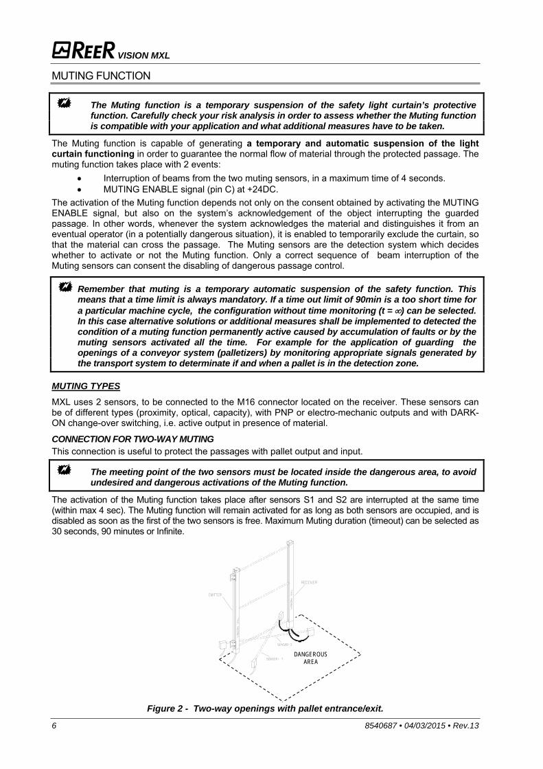
CONNECTION FOR TWO-WAY MUTING This connection is useful to protect the passages with pallet output and input.
The meeting point of the two sensors must be located inside the dangerous area, to avoid undesired and dangerous activations of the Muting function.
The activation of the Muting function takes place after sensors S1 and S2 are interrupted at the same time (within max 4 sec). The Muting function will remain activated for as long as both sensors are occupied, and is disabled as soon as the first of the two sensors is free. Maximum Muting duration (timeout) can be selected as 30 seconds, 90 minutes or Infinite.
Figure 2 - Two-way openings with pallet entrance/exit.
DANGEROUS AREA
VISION MXL
8540687 • 04/03/2015 • Rev.13 7
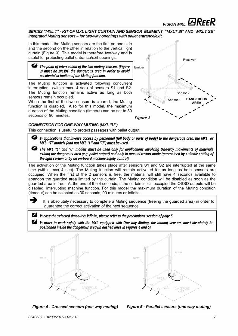
SERIES "MXL T" - KIT OF MXL LIGHT CURTAIN AND SENSOR ELEMENT “MXLT SI” AND “MXLT SE” Integrated Muting sensors – for two-way openings with pallet entrance/exit.
In this model, the Muting sensors are the first on one side and the second on the other in relation to the vertical light curtain (Figure 3). This model is therefore two-way and is useful for protecting pallet entrance/exit openings.
The point of intersection of the two muting sensors (Figure 3) must be INSIDE the dangerous area in order to avoid accidental actuation of the Muting function.
The Muting function is activated following concurrent interruption (within max. 4 sec) of sensors S1 and S2. The Muting function remains active as long as both sensors remain occupied. When the first of the two sensors is cleared, the Muting function is disabled. Also for this model, the maximum duration of the Muting condition (timeout) can be set to 30 seconds or 90 minutes.
Figure 3 CONNECTION FOR ONE-WAY MUTING (MXL "U") This connection is useful to protect passages with pallet output.
In applications that involve access by personnel (full body or parts of body) to the dangerous area, the MXL or MXL "T" models (and not MXL "L" and "U") must be used.
The MXL "L" and "U" models must be used only for applications involving One-way movements of materials exiting the dangerous area (e.g. pallet output) and only in manual restart mode (guaranteed by suitable setting of the light curtain or by an on-board machine safety control).
The activation of the Muting function takes place after sensors S1 and S2 are interrupted at the same time (within max 4 sec). The Muting function will remain activated for as long as both sensors are occupied. When the first of the 2 sensors is free, the material will still have 4 seconds available to abandon the guarded area limited by the curtain. The Muting condition will be disabled as soon as the guarded area is free. At the end of the 4 seconds, if the curtain is still occupied the OSSD outputs will be disabled, interrupting machine function. For this model the maximum duration of the Muting condition (timeout) can be selected as 30 seconds, 90 minutes or Infinite.
It is absolutely necessary to complete a Muting sequence (freeing the guarded area) in order to guarantee the correct activation of the next sequence.
In case the selected timeout is Infinite, please refer to the precautions section of page 5.
In order to work safely with the MXL equipped with One-way Muting, the muting sensors must absolutely be positioned inside the dangerous area (in dashed lines in Figures 4 and 5).
Figure 4 - Crossed sensors (one way muting)
Figure 5 - Parallel sensors (one way muting)
Emitter
Receiver
Sensor 1
Sensor 2
DDAANNGGEERROOUUSS AARREEAA
VISION MXL
8 8540687 • 04/03/2015 • Rev.13
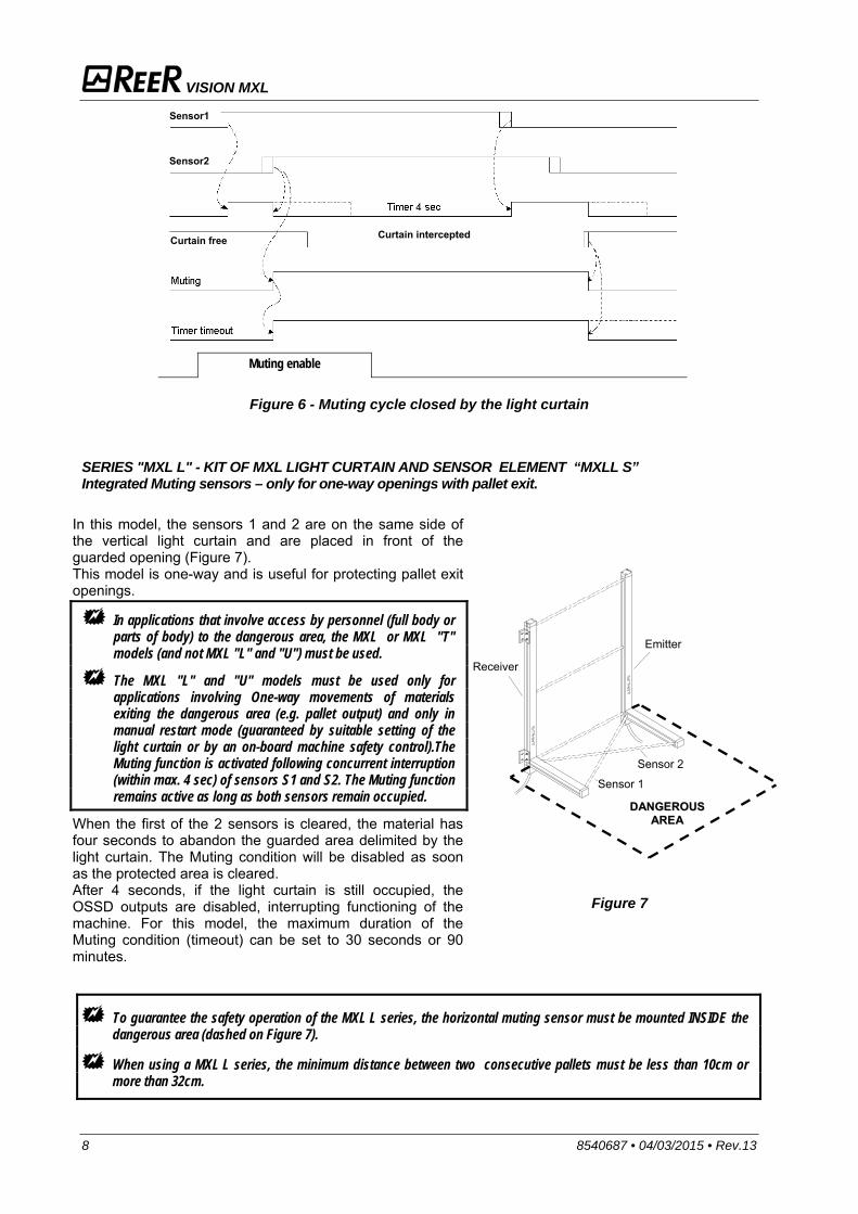
Figure 6 - Muting cycle closed by the light curtain
SERIES "MXL L" - KIT OF MXL LIGHT CURTAIN AND SENSOR ELEMENT “MXLL S” Integrated Muting sensors – only for one-way openings with pallet exit.
In this model, the sensors 1 and 2 are on the same side of the vertical light curtain and are placed in front of the guarded opening (Figure 7). This model is one-way and is useful for protecting pallet exit openings.
In applications that involve access by personnel (full body or parts of body) to the dangerous area, the MXL or MXL "T" models (and not MXL "L" and "U") must be used.
The MXL "L" and "U" models must be used only for applications involving One-way movements of materials exiting the dangerous area (e.g. pallet output) and only in manual restart mode (guaranteed by suitable setting of the light curtain or by an on-board machine safety control).The Muting function is activated following concurrent interruption (within max. 4 sec) of sensors S1 and S2. The Muting function remains active as long as both sensors remain occupied.
When the first of the 2 sensors is cleared, the material has four seconds to abandon the guarded area delimited by the light curtain. The Muting condition will be disabled as soon as the protected area is cleared. After 4 seconds, if the light curtain is still occupied, the OSSD outputs are disabled, interrupting functioning of the machine. For this model, the maximum duration of the Muting condition (timeout) can be set to 30 seconds or 90 minutes.
Figure 7
To guarantee the safety operation of the MXL L series, the horizontal muting sensor must be mounted INSIDE the dangerous area (dashed on Figure 7).
When using a MXL L series, the minimum distance between two consecutive pallets must be less than 10cm or more than 32cm.
Muting enable
Sensor1
Sensor2
Curtain free Curtain intercepted
Receiver
Emitter
Sensor 1
Sensor 2
DDAANNGGEERROOUUSS AARREEAA
VISION MXL
8540687 • 04/03/2015 • Rev.13 9
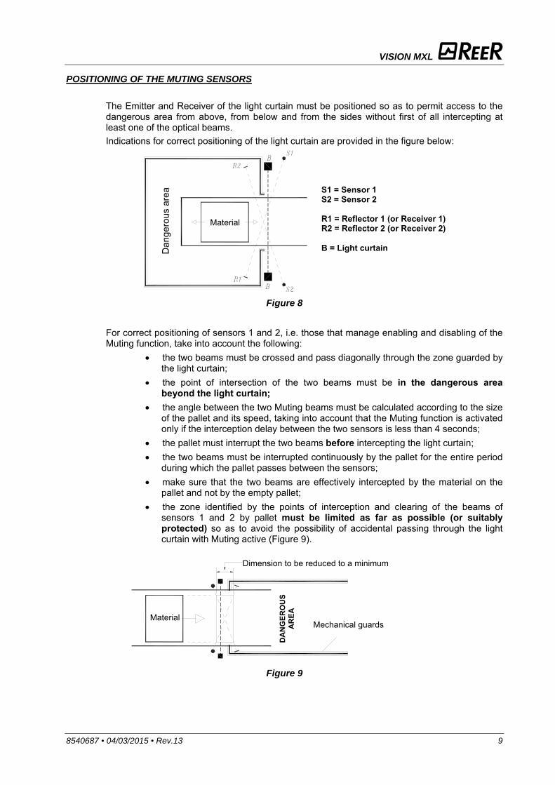
POSITIONING OF THE MUTING SENSORS The Emitter and Receiver of the light curtain must be positioned so as to permit access to the dangerous area from above, from below and from the sides without first of all intercepting at least one of the optical beams. Indications for correct positioning of the light curtain are provided in the figure below:
Figure 8
For correct positioning of sensors 1 and 2, i.e. those that manage enabling and disabling of the Muting function, take into account the following:
the two beams must be crossed and pass diagonally through the zone guarded by the light curtain;
the point of intersection of the two beams must be in the dangerous area beyond the light curtain;
the angle between the two Muting beams must be calculated according to the size of the pallet and its speed, taking into account that the Muting function is activated only if the interception delay between the two sensors is less than 4 seconds;
the pallet must interrupt the two beams before intercepting the light curtain; the two beams must be interrupted continuously by the pallet for the entire period
during which the pallet passes between the sensors; make sure that the two beams are effectively intercepted by the material on the
pallet and not by the empty pallet; the zone identified by the points of interception and clearing of the beams of
sensors 1 and 2 by pallet must be limited as far as possible (or suitably protected) so as to avoid the possibility of accidental passing through the light curtain with Muting active (Figure 9).
Figure 9
S1 = Sensor 1S2 = Sensor 2 R1 = Reflector 1 (or Receiver 1) R2 = Reflector 2 (or Receiver 2) B = Light curtain
Material
Dan
gero
us a
rea
Dimension to be reduced to a minimum
Mechanical guards Material
DA
NG
ERO
US
AR
EA

VISION MXL
10 8540687 • 04/03/2015 • Rev.13
POSITIONING
The position of the MXLE Emitter and the MXLR Receiver must prevent access to the danger zone from above, below and from the sides, unless at least one of the optical beams has been intercepted. Some useful information regarding the correct position of the light curtain is shown in the figure below.
Incorrect positioning of light curtain
Correct positioning of light curtain
Figure 10

VISION MXL
8540687 • 04/03/2015 • Rev.13 11
SAFETY DISTANCE CALCULATION
The light curtain must be installed at a distance that is greater than or equal to the minimum safety distance S, so that a dangerous point can only be reached after all hazardous machine movements have stopped (Figure 11). According to European standard EN999, the minimum safety distance S must be calculated using the following formula:
S = K (t1 + t2) + C where:
S minimum safety distance mm K approach speed of object to the dangerous area mm/sec t1 response time of the safety light curtain in seconds sec
t2 machine response time, in seconds, meaning the time
required for the machine to interrupt the dangerous movement following transmission of the stop signal
sec
c additional distance mm
The non-observance of the correct safety distance reduces or cancels the protective action of the light curtain.
If the position of the light curtain does not prevent the operator from having access to the dangerous area without being detected, additional mechanical guards must be installed to complete the system.
“S”=Safety distance
Figure 11
HAZARDOUS MACHINE
S
VISION MXL
12 8540687 • 04/03/2015 • Rev.13
VERTICAL POSITION OF THE LIGHT CURTAIN
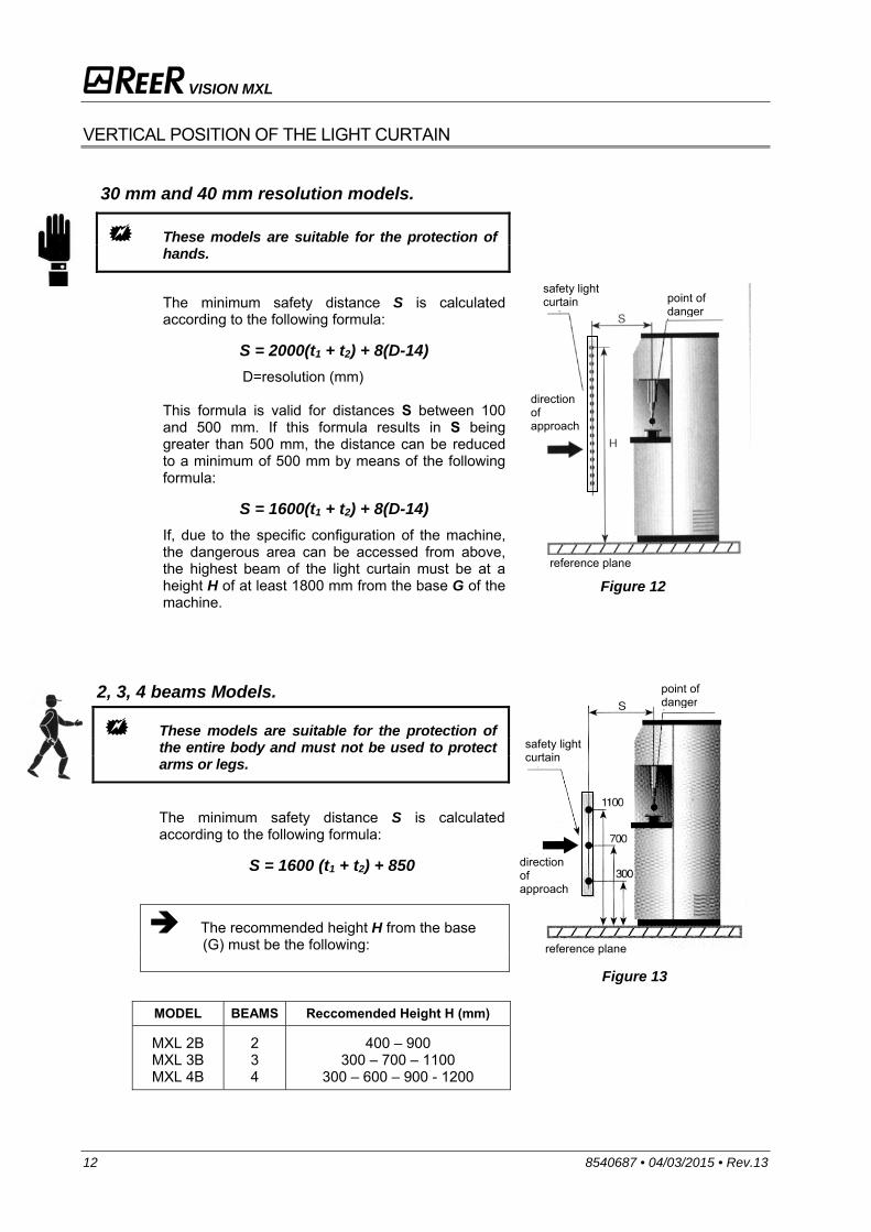
30 mm and 40 mm resolution models.
These models are suitable for the protection of hands.
The minimum safety distance S is calculated according to the following formula:
S = 2000(t1 + t2) + 8(D-14) D=resolution (mm)
This formula is valid for distances S between 100 and 500 mm. If this formula results in S being greater than 500 mm, the distance can be reduced to a minimum of 500 mm by means of the following formula:
S = 1600(t1 + t2) + 8(D-14) If, due to the specific configuration of the machine, the dangerous area can be accessed from above, the highest beam of the light curtain must be at a height H of at least 1800 mm from the base G of the machine.
Figure 12
2, 3, 4 beams Models.
These models are suitable for the protection of the entire body and must not be used to protect arms or legs.
The minimum safety distance S is calculated according to the following formula:
S = 1600 (t1 + t2) + 850
The recommended height H from the base (G) must be the following:
Figure 13
MODEL BEAMS Reccomended Height H (mm)
MXL 2B MXL 3B MXL 4B
2 3 4
400 – 900 300 – 700 – 1100
300 – 600 – 900 - 1200
safety light curtain
point of danger
direction of approach
reference plane
safety light curtain point of
danger
direction of approach
reference plane
VISION MXL
8540687 • 04/03/2015 • Rev.13 13
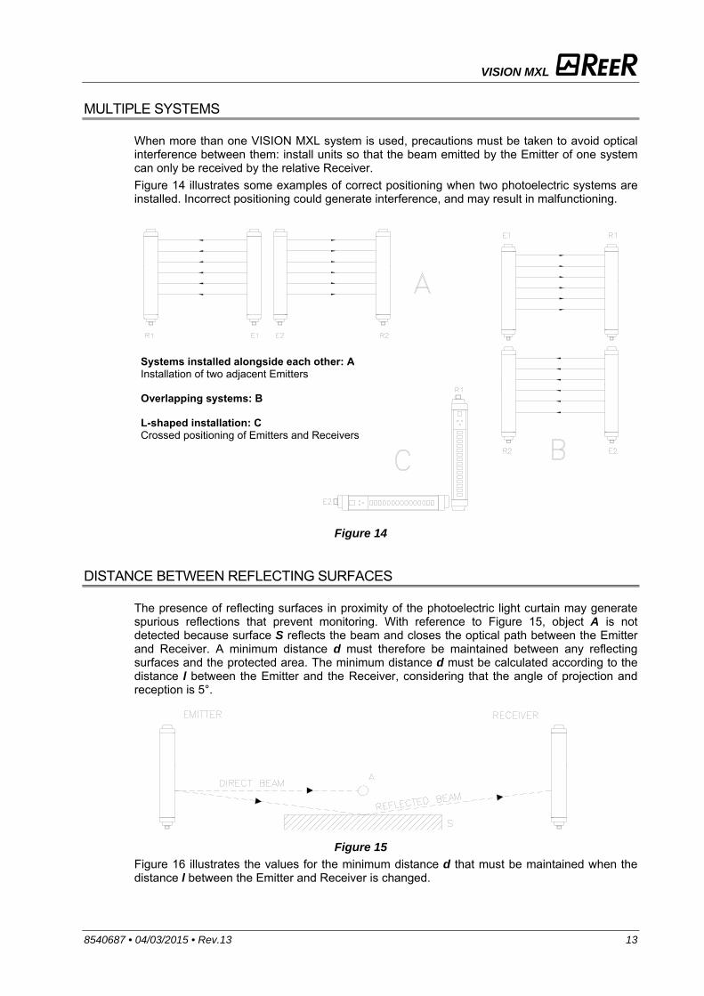
MULTIPLE SYSTEMS
When more than one VISION MXL system is used, precautions must be taken to avoid optical interference between them: install units so that the beam emitted by the Emitter of one system can only be received by the relative Receiver. Figure 14 illustrates some examples of correct positioning when two photoelectric systems are installed. Incorrect positioning could generate interference, and may result in malfunctioning.
Figure 14
DISTANCE BETWEEN REFLECTING SURFACES
The presence of reflecting surfaces in proximity of the photoelectric light curtain may generate spurious reflections that prevent monitoring. With reference to Figure 15, object A is not detected because surface S reflects the beam and closes the optical path between the Emitter and Receiver. A minimum distance d must therefore be maintained between any reflecting surfaces and the protected area. The minimum distance d must be calculated according to the distance l between the Emitter and the Receiver, considering that the angle of projection and reception is 5°.
Figure 15
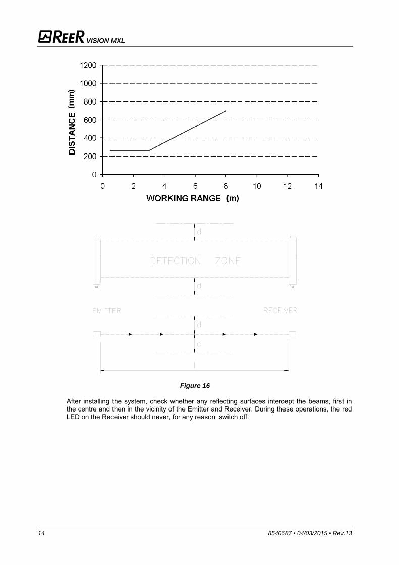
Figure 16 illustrates the values for the minimum distance d that must be maintained when the distance l between the Emitter and Receiver is changed.
Systems installed alongside each other: AInstallation of two adjacent Emitters Overlapping systems: B L-shaped installation: C Crossed positioning of Emitters and Receivers
VISION MXL
14 8540687 • 04/03/2015 • Rev.13
Figure 16
After installing the system, check whether any reflecting surfaces intercept the beams, first in the centre and then in the vicinity of the Emitter and Receiver. During these operations, the red LED on the Receiver should never, for any reason switch off.

VISION MXL
8540687 • 04/03/2015 • Rev.13 15
MECHANICAL ASSEMBLY AND OPTICAL ALIGNMENT
The Emitter and the Receiver must be assembled opposite each other (at a distance specified in the technical data sheet). Use the fastening brackets and inserts supplied with the system to place the Emitter and the Receiver so that these are aligned and parallel to each other and with the connectors facing the same way. Depending on the dimensions and the shape of the support on which they are to be installed, the Emitter and Receiver must be assembled with the fastening inserts at the back, or else by fitting these in the side groove (Figure 17). Perfect alignment of the Emitter and Receiver is essential in order to assure correct light curtain operation. The indicator LEDs on the Emitter and Receiver facilitate this operation.
To perform an easier alignment the use of SFB circular brackets is necessary. These are available on request (ordering code 1330974).
Figure 17
Position the optical axis of the first and last beam of the Emitter on the same axis as
that of the corresponding beams on the Receiver. Move the Emitter in order to find the area within which the green LED on the Receiver
stays on, then position the first beam of the Emitter (the one close to the indicator LEDs) in the centre of this area.
Using this beam as a pivot, effect small sideways movements of the opposite end to move to the protected area clear condition. The green LED on the Receiver will indicate this condition.
Lock the Emitter and Receiver in place.
In case the Emitter and the Receiver are assembled in areas subject to strong vibration, in order to prevent damages to the equipment it is necessary to use anti-vibration devices (code SAV-3 1200088, code SAV-4 1200089).
VISION MXL
16 8540687 • 04/03/2015 • Rev.13
ELECTRICAL CONNECTIONS
WARNINGS Before making the electrical connections, make sure that the supply voltage complies with that specified in the technical data sheet.
Emitter and Receiver units must be supplied with 24Vdc±20% power supply that guarantee safe isolation from main voltage.
The external power supply must comply with the standard EN 60204-1 (Chapter 6.4).
The electrical connections must be made according to the diagrams in this manual. In particular, do not connect other devices to the connectors of the Emitter and Receiver. For reliability of operation, when a diode jumper supply unit is used, its output capacity must be at least 2000µF for each absorbed A.
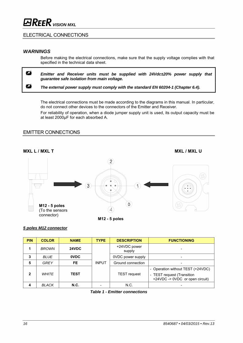
EMITTER CONNECTIONS
MXL L / MXL T MXL / MXL U
5 poles M12 connector
PIN COLOR NAME TYPE DESCRIPTION FUNCTIONING
1 BROWN 24VDC
INPUT
+24VDC power supply -
3 BLUE 0VDC 0VDC power supply - 5 GREY FE Ground connection -
2 WHITE TEST TEST request - Operation without TEST (+24VDC) - TEST request (Transition +24VDC -> 0VDC or open circuit)
4 BLACK N.C. - N.C. -
Table 1 - Emitter connections
M12 - 5 poles (To the sensors connector)
M12 - 5 poles

VISION MXL
8540687 • 04/03/2015 • Rev.13 17
RECEIVER CONNECTIONS MXL L / MXL T MXL / MXL U
12 poles M16 connector
PIN COLOR NAME TYPE DESCRIPTION FUNCTIONING
D GREY SUPPLY_A - Supply A SUPPLY_A : 0Vdc SUPPLY_B : 24Vdc
MANUAL (see Table 4)
B GREEN SUPPLY_B - Supply B SUPPLY_A : 24Vdc SUPPLY_B : 0Vdc
AUTOMATIC (see Table 3)
H PURPLE FE - Ground connection - A GREY-PINK OSSD1 OUTPUT
Static safety outputs PNP active high K YELLOW OSSD2 OUTPUT
L BROWN SENSOR1 INPUT Muting sensors
< 5VDC (with <3mA) : sensor free
11÷30 VDC (with 630mA): sensor occupied M BLUE SENSOR2 INPUT
J RED-BLUE FBK_K1K2/ RESTART INPUT
External contactors feedback +
RESTART input < 5VDC (I <3mA) : OFF
11÷30 VDC (I = 630mA): ON F RED OVERRIDE INPUT Override request
C WHITE MUTING ENABLE INPUT Muting enabling
request E PINK TIMEOUT INPUT Timeout Selection G BLACK MUT_LAMP OUTPUT Muting lamp output PNP active high
Table 2 - Receiver connections
5 poles M12 connector This connector must be wired to the 5 poles M12 male connector connected to the muting arms.
WARNINGS REGARDING THE CONNECTION CABLES
For connections over 50m long, use cables with a cross-section area of 1 mm2. The power supply to the light curtain should be kept separate from that to other electric power
equipment (electric motors, inverters, frequency converters) or other sources of disturbance. Connect the Emitter and the Receiver to the ground outlet. The connection cables must follow a different route to that of the other power cables.
M12 - 5 poles (To the sensors connector) M16 - 12 poles
VISION MXL
18 8540687 • 04/03/2015 • Rev.13
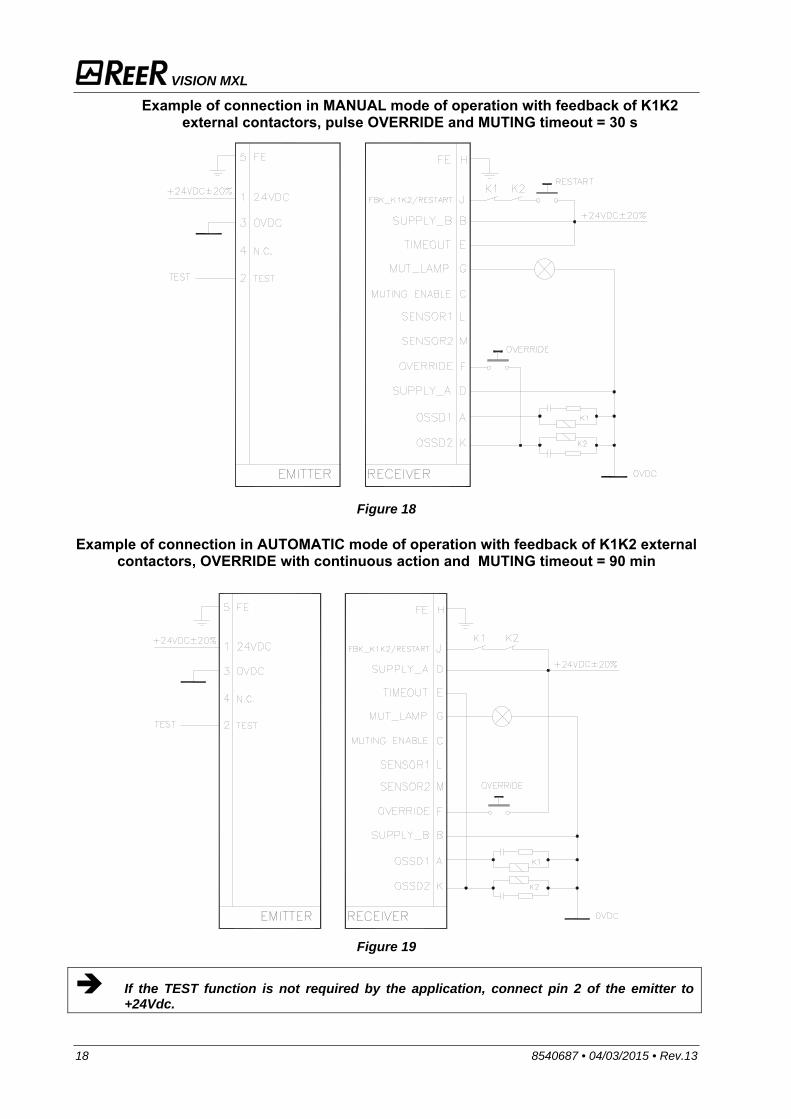
Example of connection in MANUAL mode of operation with feedback of K1K2 external contactors, pulse OVERRIDE and MUTING timeout = 30 s
Figure 18
Example of connection in AUTOMATIC mode of operation with feedback of K1K2 external
contactors, OVERRIDE with continuous action and MUTING timeout = 90 min
Figure 19
If the TEST function is not required by the application, connect pin 2 of the emitter to +24Vdc.
VISION MXL
8540687 • 04/03/2015 • Rev.13 19
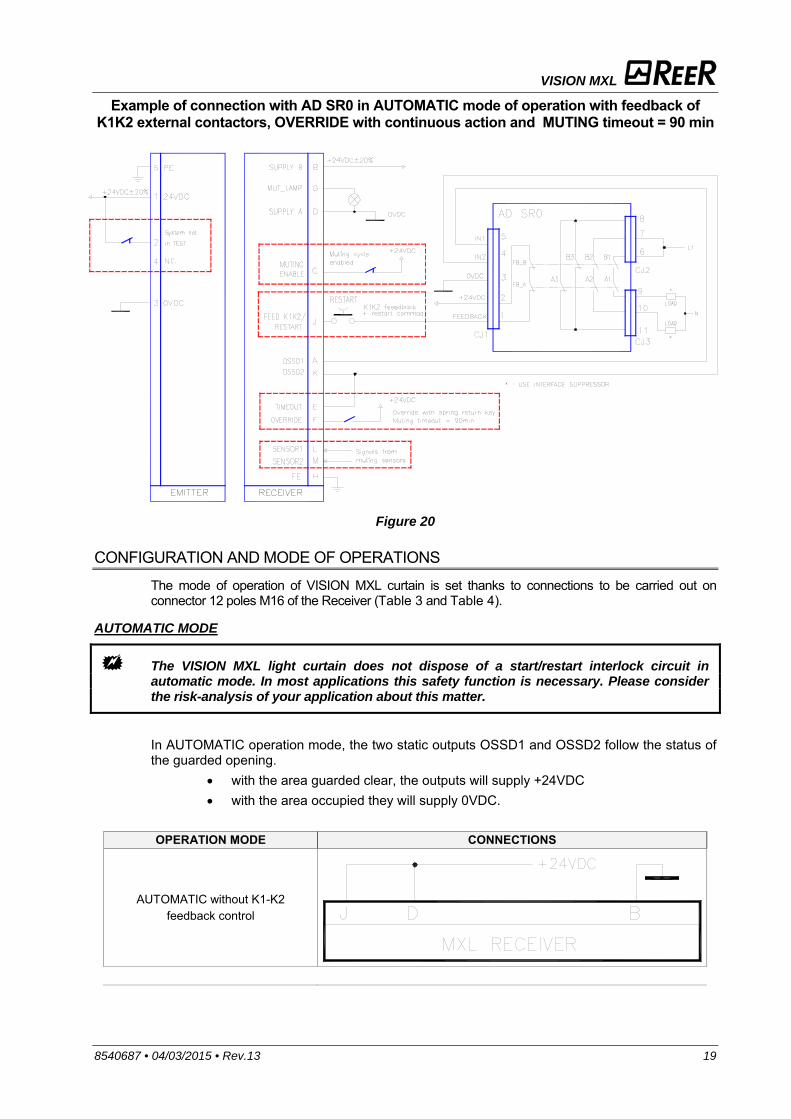
Example of connection with AD SR0 in AUTOMATIC mode of operation with feedback of K1K2 external contactors, OVERRIDE with continuous action and MUTING timeout = 90 min
Figure 20
CONFIGURATION AND MODE OF OPERATIONS
The mode of operation of VISION MXL curtain is set thanks to connections to be carried out on connector 12 poles M16 of the Receiver (Table 3 and Table 4).
AUTOMATIC MODE
The VISION MXL light curtain does not dispose of a start/restart interlock circuit in automatic mode. In most applications this safety function is necessary. Please consider the risk-analysis of your application about this matter.
In AUTOMATIC operation mode, the two static outputs OSSD1 and OSSD2 follow the status of the guarded opening.
with the area guarded clear, the outputs will supply +24VDC with the area occupied they will supply 0VDC.
OPERATION MODE CONNECTIONS
AUTOMATIC without K1-K2 feedback control
VISION MXL
20 8540687 • 04/03/2015 • Rev.13
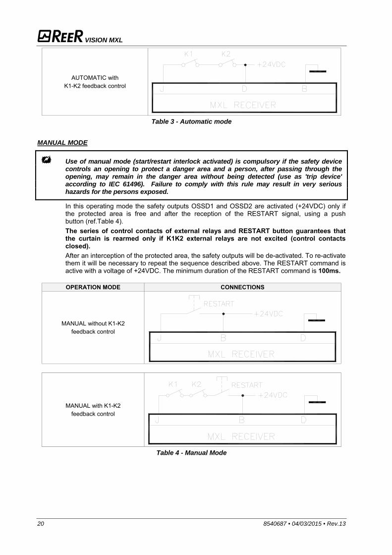
AUTOMATIC with K1-K2 feedback control
Table 3 - Automatic mode
MANUAL MODE
Use of manual mode (start/restart interlock activated) is compulsory if the safety device controls an opening to protect a danger area and a person, after passing through the opening, may remain in the danger area without being detected (use as 'trip device' according to IEC 61496). Failure to comply with this rule may result in very serious hazards for the persons exposed.
In this operating mode the safety outputs OSSD1 and OSSD2 are activated (+24VDC) only if the protected area is free and after the reception of the RESTART signal, using a push button (ref.Table 4). The series of control contacts of external relays and RESTART button guarantees that the curtain is rearmed only if K1K2 external relays are not excited (control contacts closed). After an interception of the protected area, the safety outputs will be de-activated. To re-activate them it will be necessary to repeat the sequence described above. The RESTART command is active with a voltage of +24VDC. The minimum duration of the RESTART command is 100ms.
OPERATION MODE CONNECTIONS
MANUAL without K1-K2 feedback control
MANUAL with K1-K2 feedback control
Table 4 - Manual Mode
VISION MXL
8540687 • 04/03/2015 • Rev.13 21
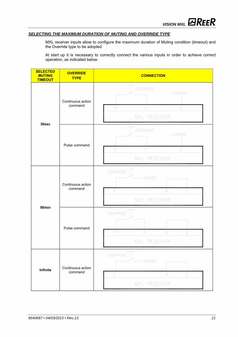
SELECTING THE MAXIMUM DURATION OF MUTING AND OVERRIDE TYPE
MXL receiver inputs allow to configure the maximum duration of Muting condition (timeout) and the Override type to be adopted.
At start up it is necessary to correctly connect the various inputs in order to achieve correct operation, as indicated below.
SELECTED MUTING
TIMEOUT
OVERRIDE TYPE CONNECTION
30sec
Continuous action command
Pulse command
90min
Continuous action command
Pulse command
Infinite Continuous action command
VISION MXL
22 8540687 • 04/03/2015 • Rev.13
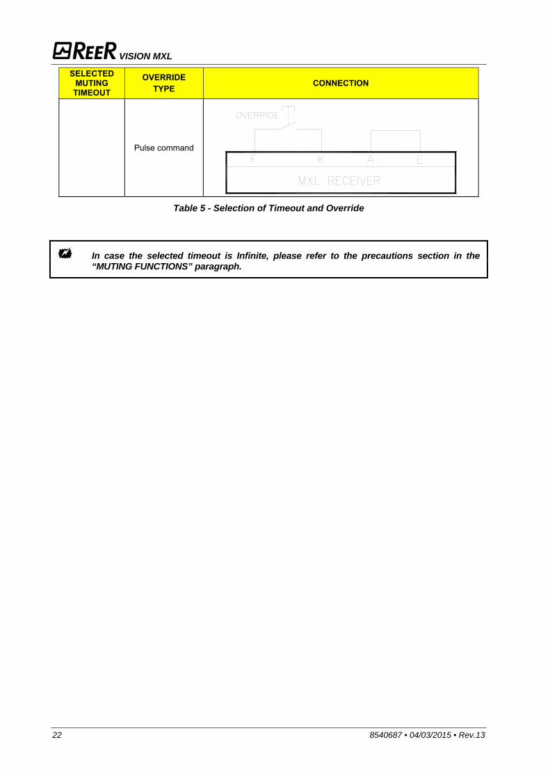
SELECTED MUTING
TIMEOUT
OVERRIDE TYPE CONNECTION
Pulse command
Table 5 - Selection of Timeout and Override
In case the selected timeout is Infinite, please refer to the precautions section in the “MUTING FUNCTIONS” paragraph.
VISION MXL
8540687 • 04/03/2015 • Rev.13 23
MUTING OVERRIDE FUNCTION The OVERRIDE function must be used when the machine stops due to incorrect Muting activation sequences with the material obstructing the guarded opening. In this situation, the OSSD outputs are not active as the light curtain and/or at least one Muting sensor is occupied. In this condition the OVERRIDE request led blinks.
This function activates the OSSD outputs making it possible to remove the material that is obstructing the opening concerned; moreover the Override/Muting lamp blinks.
Throughout the entire phase during which the OVERRIDE function is active, the Override/Muting lamp is blinking. Check efficiency of this lamp periodically (during the Muting or Override phases).
Warning!! The Override with pulse command automatically activates the outputs of the light curtain until both the light curtain and the muting sensors are free of obstacles again. During this period, the light curtain is unable to protect access to the guarded opening. Therefore, all operations must be carried out under the strict supervision of expert personnel.
The operator will use the Override mode previously selected (ref. Table 5).
1. Override with continuous action command 2. Override with pulse command
Override with continuous action command. To activate this function the OVERRIDE button must be kept pressed for the entire duration of the successive operations. The maximum override duration is 15 minutes; it can be stopped for two different causes.
When the button is released or after 15 minutes the override will be terminated, de-activating the OSSD outputs, turning off the muting lamp and showing normal condition on the display. A new override condition can be started, releasing and rearming the selector.
Once the opening has been cleared and the sensors are free again, override ends and GUARD condition (light curtain in normal operation) is activated without necessity of further commands.
Override with pulse command. To activate this function the OVERRIDE button must be kept pressed for a maximum duration of 400 ms. The override condition can last a maximum of 15 minutes (repeatable). The function can only be re-started by pressing the pushbutton again (subject to the following conditions):
1. Maximum total OVERRIDE time (after n consecutive requests) = 60 min 2. Maximum number of consecutive requests for OVERRIDE = 30.
The override condition ends when the barrier and sensors are cleared (entrance clear) and the GUARD condition is re-enabled (barrier fully operational) without sending any further commands. The timer (point 1) and counter (point 2) are reset when one of the following conditions occurs:
- A correct muting sequence. - A system reset (switched off and then turned on).

VISION MXL
24 8540687 • 04/03/2015 • Rev.13
OPERATION AND TECHNICAL DATA SIGNALS
The LEDs showed on Emitter and Receiver units labels are visualized depending on the system operation phase. The tables below show the different signals (ref. Figure 21).
Figure 21
EMITTER SIGNALS
Normal operation
MEANING RED (3) GREEN (2) (TEST) YELLOW (1)
System start up. Initial TEST ON OFF ON
Normal operation OFF ON OFF
TEST condition OFF ON ON
RECEIVER SIGNALS Normal operation
MEANING SEMAPHORE (7) OVERRIDE (8) SENSOR1 (5) SENSOR2 (6) MUTING (4)
RED/ GREEN/YELLOW YELLOW YELLOW YELLOW ORANGE
System start up. Initial TEST RED ON ON ON ON First 5 sec: Manual with Muting Timeout = 30 s OFF ON ON ON OFF
First 5 sec: Manual with Muting Timeout = 90 min OFF ON ON OFF OFF
First 5 sec: Manual with Muting Timeout = OFF ON OFF ON OFF
First 5 sec: Automatic with Muting Timeout = 30s OFF OFF ON ON OFF
First 5 sec: Automatic with Muting Timeout = 90min OFF OFF ON OFF OFF
First 5 sec: Automatic with Muting Timeout = OFF OFF OFF ON OFF
BREAK (A) condition RED OFF sens1 status sens2 status OFF CLEAR (B) condition YELLOW OFF OFF OFF OFF MUTING condition GREEN OFF
sens1 status sens2 status
ON GUARD (C) condition GREEN OFF OFF OVERRIDE (D) condition GREEN ON OFF Request of OVERRIDE with BREAK RED
Blinking OFF
Request of OVERRIDE with S1 or S2 occupied OFF OFF
(A) Curtain occupied – outputs disabled; (B) Curtain free – outputs disabled – Waiting for restart (C) Curtain free – outputs enabled; (D) Curtain occupied – outputs enabled
1
2 3
4
5 6
8
7
EMITTER RECEIVER
VISION MXL
8540687 • 04/03/2015 • Rev.13 25
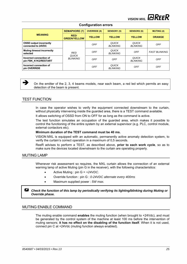
Configuration errors
MEANING SEMAPHORE (7) OVERRIDE (8) SENSOR1 (5) SENSOR2 (6) MUTING (4)
RED/ GREEN/YELLOW YELLOW YELLOW YELLOW ORANGE
OSSD output incorrectly connected to 24VDC
RED QUICK
BLINKING
OFF QUICK BLINKING
QUICK BLINKING OFF
Muting timeout incorrectly selected OFF QUICK
BLINKING OFF FAST BLINKING
Incorrect connection of pin FBK_K1K2/RESTART OFF OFF QUICK
BLINKING OFF
Incorrect connection of pin OVERRIDE OFF QUICK
BLINKING OFF OFF
On the emitter of the 2, 3, 4 beams models, near each beam, a red led which permits an easy detection of the beam is present.
TEST FUNCTION
In case the operator wishes to verify the equipment connected downstream to the curtain, without physically intervening inside the guarded area, there is a TEST command available. It allows switching of OSSD from ON to OFF for as long as the command is active. The test function simulates an occupation of the guarded area, which makes it possible to control the functioning of the entire system by an external supervisor (e.g. PLC, control module, external contactors etc). Minimum duration of the TEST command must be 40 ms. VISION MXL is equipped with an automatic, permanently active anomaly detection system, to verify the curtain’s correct operation in a maximum of 0,5 seconds. ReeR advises to perform a TEST, as described above, prior to each work cycle, so as to make sure the devices located downstream to the curtain are operating properly.
MUTING LAMP
Whenever risk assessment so requires, the MXL curtain allows the connection of an external warning lamp of active Muting (pin G in the receiver), with the following characteristics:
Active Muting : pin G = +24VDC. Override function : pin G : 0-24VDC alternate every 400ms Maximum supplied power : 5W max.
Check the function of this lamp by periodically verifying its lighting/blinking during Muting or Override phase.
MUTING ENABLE COMMAND
The muting enable command enables the muting function (when brought to +24Vdc), and must be generated by the control system of the machine at least 100 ms before the intervention of muting sensors; it has no effect on the disabling of the function itself. When it is not used, connect pin C at +24Vdc (muting function always enabled).
VISION MXL
26 8540687 • 04/03/2015 • Rev.13
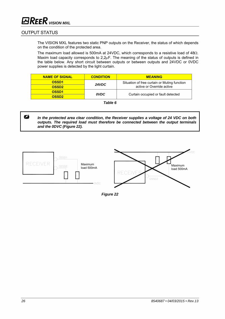
OUTPUT STATUS
The VISION MXL features two static PNP outputs on the Receiver, the status of which depends on the condition of the protected area. The maximum load allowed is 500mA at 24VDC, which corresponds to a resistive load of 48. Maxim load capacity corresponds to 2,2F. The meaning of the status of outputs is defined in the table below. Any short circuit between outputs or between outputs and 24VDC or 0VDC power supplies is detected by the light curtain.
NAME OF SIGNAL CONDITION MEANING
OSSD1 24VDC Situation of free curtain or Muting function
active or Override active OSSD2 OSSD1
0VDC Curtain occupied or fault detected OSSD2 Table 6
In the protected area clear condition, the Receiver supplies a voltage of 24 VDC on both outputs. The required load must therefore be connected between the output terminals and the 0DVC (Figure 22).
Figure 22
Maximum load 500mA
Maximum load 500mA

VISION MXL
8540687 • 04/03/2015 • Rev.13 27
TECHNICAL SPECIFICATIONS
TECHNICAL SPECIFICATIONS Safety category 2 Resolutions / N. of beams 30 - 40 mm / 2 - 3 - 4 beam
Protected height mm 160 – 1210 (30mm) / 160 – 1810 (40mm)
Working range m refer to the tables below Connections M16 - 12 poles for RX - M12 - 5 poles for TX
Power supply 24 Vdc 20%
Safety outputs 2 PNP – 500mA @ 24VDC EDM function Present on RX – selectable
Restart Auto/Manual Present on RX – selectable
Muting Function Integrated, with 2-signal logic, 4 seconds simultaneity control, timeout selectable as 30 s, 90 min or
Muting Enable Selectable MUTING ENABLE input (Muting enabled with 24Vdc)
Muting signal input (MXL - MXL U models only) 2 dark on – for contact relay NA or static output PNP 24Vdc
Lamp output/ muting LED 24Vdc - 5W max. (lamp presence not obligatory)
Override Function Selectable with continuous manual action or impulse commands
Response time ms 4 37 (see following tables)
Internal test execution time s max 0,5
Test input Present on TX
Signals and troubleshooting LED signals
Max. conn. length m 100
Operating temperature °C 0 +55
Storage temperature °C -20 +70
Protection rating IP 65
Dimensions of section mm 35 x 45 Max. consumption W 2 (Emitter) 2 (Receiver)
Light curtain lifetime 20 years
Safety level Type 2 IEC 61496-1:(ed.3)
IEC 61496-2:(ed.3) SILCL 1 IEC 62061:(ed.1) PL c - Cat.2 EN ISO 13849-1:2008
30 mm Resolution Models MXL / MXL U
153 303 453 603 753 903 1053 1203 Working range m 0,3 8 Number of beams 8 16 24 32 40 48 56 64 Response time ms 7 11,5 16 20 24 28,5 33 37 Overall light curtain ht. mm 261 411 561 711 861 1011 1161 1311 PFHd * 2,73E-8 3,85E-8 4,97E-8 6,09E-8 7,21E-8 8,33E-8 9,45E-8 1,06E-7 DCavg # 94,6% 94,2% 94,0% 93,9% 93,8% 93,7% 93,7% 93,6% MTTFd # years 100,00 98,29 86,12 76,64 69,03 CCF # 80%
* IEC 62061 # ISO 13849-1
VISION MXL
28 8540687 • 04/03/2015 • Rev.13
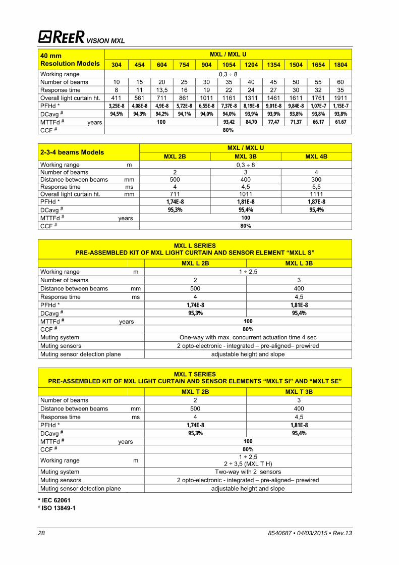
40 mm Resolution Models
MXL / MXL U 304 454 604 754 904 1054 1204 1354 1504 1654 1804
Working range 0,3 8 Number of beams 10 15 20 25 30 35 40 45 50 55 60 Response time 8 11 13,5 16 19 22 24 27 30 32 35 Overall light curtain ht. 411 561 711 861 1011 1161 1311 1461 1611 1761 1911 PFHd * 3,25E-8 4,08E-8 4,9E-8 5,72E-8 6,55E-8 7,37E-8 8,19E-8 9,01E-8 9,84E-8 1,07E-7 1,15E-7 DCavg # 94,5% 94,3% 94,2% 94,1% 94,0% 94,0% 93,9% 93,9% 93,8% 93,8% 93,8% MTTFd # years 100 93,42 84,70 77,47 71,37 66.17 61.67 CCF # 80%
2-3-4 beams Models
MXL / MXL U MXL 2B MXL 3B MXL 4B
Working range m 0,3 8 Number of beams 2 3 4 Distance between beams mm 500 400 300 Response time ms 4 4,5 5,5 Overall light curtain ht. mm 711 1011 1111 PFHd * 1,74E-8 1,81E-8 1,87E-8 DCavg # 95,3% 95,4% 95,4% MTTFd # years 100 CCF # 80%
MXL L SERIES
PRE-ASSEMBLED KIT OF MXL LIGHT CURTAIN AND SENSOR ELEMENT “MXLL S” MXL L 2B MXL L 3B Working range m 1 ÷ 2,5 Number of beams 2 3 Distance between beams mm 500 400 Response time ms 4 4,5 PFHd * 1,74E-8 1,81E-8 DCavg # 95,3% 95,4% MTTFd # years 100 CCF # 80% Muting system One-way with max. concurrent actuation time 4 sec Muting sensors 2 opto-electronic - integrated – pre-aligned– prewired Muting sensor detection plane adjustable height and slope
MXL T SERIES
PRE-ASSEMBLED KIT OF MXL LIGHT CURTAIN AND SENSOR ELEMENTS “MXLT SI” AND “MXLT SE” MXL T 2B MXL T 3B Number of beams 2 3 Distance between beams mm 500 400 Response time ms 4 4,5 PFHd * 1,74E-8 1,81E-8 DCavg # 95,3% 95,4% MTTFd # years 100 CCF # 80%
Working range m 1 ÷ 2,5 2 ÷ 3,5 (MXL T H)
Muting system Two-way with 2 sensors Muting sensors 2 opto-electronic - integrated – pre-aligned– prewired Muting sensor detection plane adjustable height and slope
* IEC 62061 # ISO 13849-1
VISION MXL
8540687 • 04/03/2015 • Rev.13 29
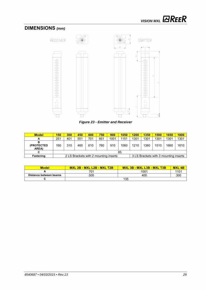
DIMENSIONS (mm)
Figure 23 - Emitter and Receiver
Model 150 300 450 600 750 900 1050 1200 1350 1500 1650 1800A 251 401 551 701 851 1001 1151 1301 1301 1301 1301 1301 B
(PROTECTED AREA)
160 310 460 610 760 910 1060 1210 1360 1510 1660 1810
C 85 Fastening 2 LS Brackets with 2 mounting inserts 3 LS Brackets with 3 mounting inserts
Model MXL 2B - MXL L2B - MXL T2B MXL 3B - MXL L3B - MXL T3B MXL 4BA 701 1001 1101
Distance between beams 500 400 300 C 135
VISION MXL
30 8540687 • 04/03/2015 • Rev.13
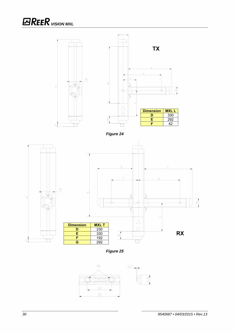
Figure 24
Figure 25
Dimension MXL L D 330 E 292 F 42
Dimension MXL TD 230 E 330 F 192 G 292
RX
TX
VISION MXL
8540687 • 04/03/2015 • Rev.13 31
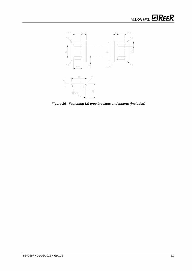
Figure 26 - Fastening LS type brackets and inserts (included)
VISION MXL
32 8540687 • 04/03/2015 • Rev.13
CHECKOUTS AND MAINTENANCE
VERIFICATION OF LIGHT CURTAIN EFFICIENCY
Before each work shift or just after switching on, check the correct operation of the photoelectric light curtain.
Proceed as follows, intercepting the beams using the appropriate test object (available as accessory, free of charge).
The correct test object must be used for testing, depending on the light curtain resolution. See page 26 for the correct ordering code.
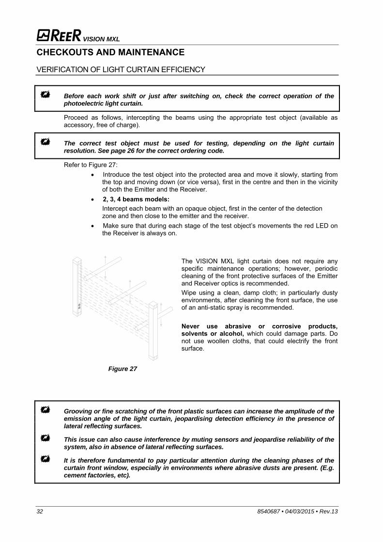
Refer to Figure 27: Introduce the test object into the protected area and move it slowly, starting from
the top and moving down (or vice versa), first in the centre and then in the vicinity of both the Emitter and the Receiver.
2, 3, 4 beams models: Intercept each beam with an opaque object, first in the center of the detection zone and then close to the emitter and the receiver.
Make sure that during each stage of the test object’s movements the red LED on the Receiver is always on.
Figure 27
The VISION MXL light curtain does not require any specific maintenance operations; however, periodic cleaning of the front protective surfaces of the Emitter and Receiver optics is recommended. Wipe using a clean, damp cloth; in particularly dusty environments, after cleaning the front surface, the use of an anti-static spray is recommended. Never use abrasive or corrosive products, solvents or alcohol, which could damage parts. Do not use woollen cloths, that could electrify the front surface.
Grooving or fine scratching of the front plastic surfaces can increase the amplitude of the emission angle of the light curtain, jeopardising detection efficiency in the presence of lateral reflecting surfaces.
This issue can also cause interference by muting sensors and jeopardise reliability of the system, also in absence of lateral reflecting surfaces.
It is therefore fundamental to pay particular attention during the cleaning phases of the curtain front window, especially in environments where abrasive dusts are present. (E.g. cement factories, etc).
VISION MXL
8540687 • 04/03/2015 • Rev.13 33
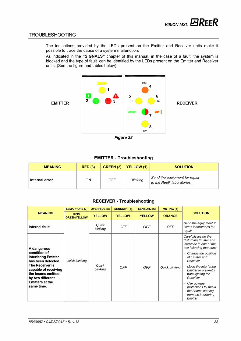
TROUBLESHOOTING
The indications provided by the LEDs present on the Emitter and Receiver units make it possible to trace the cause of a system malfunction. As indicated in the “SIGNALS” chapter of this manual, in the case of a fault, the system is blocked and the type of fault can be identified by the LEDs present on the Emitter and Receiver units. (See the figure and tables below).
Figure 28
EMITTER - Troubleshooting
MEANING RED (3) GREEN (2) YELLOW (1) SOLUTION
Internal error ON OFF Blinking Send the equipment for repair to the ReeR laboratories.
RECEIVER - Troubleshooting
MEANING SEMAPHORE (7) OVERRIDE (8) SENSOR1 (5) SENSOR2 (6) MUTING (4)
SOLUTION RED/ GREEN/YELLOW YELLOW YELLOW YELLOW ORANGE
Internal fault
Quick blinking
Quick blinking OFF OFF OFF
Send the equipment to ReeR laboratories for repair
A dangerous condition of interfering Emitter has been detected. The Receiver is capable of receiving the beams emitted by two different Emitters at the same time.
Quick blinking OFF OFF Quick blinking
Carefully locate the disturbing Emitter and intervene in one of the two following manners:
– Change the position of Emitter and Receiver
– Move the interfering Emitter to prevent it from lighting the Receiver
– Use opaque protections to shield the beams coming from the interfering Emitter
1
2 3
4
5 6
8
7
EMITTER RECEIVER

VISION MXL
34 8540687 • 04/03/2015 • Rev.13
MEANING SEMAPHORE (7) OVERRIDE (8) SENSOR1 (5) SENSOR2 (6) MUTING (4)
SOLUTION RED/ GREEN/YELLOW YELLOW YELLOW YELLOW ORANGE
Fault at OSSD static outputs
Quick blinking
OFF Quick blinking Quick blinking OFF
Carefully verify the connection of pins A and K (OSSD) on the connector.
If necessary, re-dimension the load by reducing the requested current to a maximum of 500 mA (2,2F)
Overload of OSSD static outputs
Short-circuit of OSSD static outputs
Overload of Muting light OFF OFF OFF Quick blinking
Verify the presence and the efficiency of the MUTING light.
Override with pulse command expired Blinking Blinking Blinking Blinking Blinking Reset the system
RECEIVER - Configuration error
MEANING SEMAPHORE (7) OVERRIDE (8) SENSOR1 (5) SENSOR2 (6) MUTING (4)
SOLUTION Red/ Green/Yellow YELLOW YELLOW YELLOW ORANGE
OSSD output incorrectly connected at 24VDC
RED Quick blinking
OFF Quick blinking Quick blinking OFF
Verify connections
Muting timeout incorrectly selected OFF Quick blinking OFF Quick blinking
Incorrect connection of pin FBK_K1K2/RESTART OFF OFF Quick blinking OFF
Incorrect connection of pin OVERRIDE OFF Quick blinking OFF OFF
In any case, when faced with a system stoppage, switch the system off and then on again, to exclude any occasional electromagnetic disturbances. Should the problem persist, contact ReeR’s service department. In case of continued malfunctioning:
make sure that the Emitter and the Receiver are correctly aligned and that the front surfaces are perfectly clean.
verify the integrity of electrical connections and check that these have been made correctly;
check that the supply voltage levels comply with those specified in the technical data sheet;
The light curtain power supply should be kept separate from that of the other electric power equipment (electric motors, inverters, frequency converters) or other sources of disturbance.
If it is not possible to clearly identify the malfunction and to remedy it, stop the machine and contact Reer's Assistance Service.
If correct system operation cannot be restored after carrying out the above procedures, send the equipment to ReeR’s laboratories, complete with all parts, stating clearly:
the product code number (the P/N field is shown on the product label) serial number (the S/N field is shown on the product label) date of purchase; period of operation; type of application; fault.

VISION MXL
8540687 • 04/03/2015 • Rev.13 35
SPARE PARTS
MODEL ARTICLE CODE
AD SR0 AD SR0 Safety Relay 1330902
AD SR0A AD SR0A Safety Relay 1330903
MXJB1 Muting junction Box 1360934
MXJB3 Muting junction Box 1360935
CD5 Straight 5-pin M12 female connector, 5 m cable 1330950
CD95 90° 5-pin M12 female connector, 5 m cable 1330951
CD15 Straight 5-pin M12 female connector, 15 m cable 1330952
CD915 90° 5-pin M12 female connector, 15 m cable 1330953
CDM9 Straight 5-pin M12 female connector PG9 1330954
CDM99 90° 5-pin M12 female connector PG9 1330955
C12D3 Straight 12-pin M16 female connector, 3 m cable 1330991
C12D5 Straight 12-pin M16 female connector, 5 m cable 1330992
C12D10 Straight 12-pin M16 female connector, 10 m cable 1330993
CMBR3 Straight M23/M16 female connectors, pre-wired 3m cable 1360975
CMBR5 Straight M23/M16 female connectors, pre-wired 5m cable 1360976
CMBR10 Straight M23/M16 female connectors, pre-wired 10m cable 1360977
TR30 30mm diameter test rod 1330962
TR40 40mm diameter test rod 1330963
FB 4 Set of 4 fastening brackets 1330970
FB 6 Set of 6 fastening brackets 1330971
FI 4 Set of 4 fastening inserts 1330972
FI 6 Set of 6 fastening inserts 1330973
SFB Set of 4 swivel fastening brackets 1330974
SAV-3 Set of 2 anti-vibration supports 1200088
SAV-4 Set of 3 anti-vibration supports 1200089

VISION MXL
36 8540687 • 04/03/2015 • Rev.13
GUARANTEE All new VISION MXL systems are guaranteed by ReeR for a period of 12 (twelve) months under normal working conditions, against defects due to faulty materials and workmanship. During the aforesaid period, ReeR promises to replace faulty parts free of charge. This guarantee covers both material and labour. ReeR reserves the right to decide whether to repair equipment or replace it with equipment of the same type or having the same characteristics.
The validity of this guarantee is subject to the following conditions:
The user must notify ReeR of the fault within twelve months following the date of delivery of the product.
The equipment and all parts thereof must be in the condition in which they were supplied by ReeR.
The defect or malfunction must not arise directly or indirectly from: – Improper use – Non-observance of the instructions for use; – Negligence, inexperience, improper maintenance; – Repairs, modifications and adjustments carried out by personnel not authorised by
ReeR, tampering, etc.; – Accidents or collisions (also during transportation or due to acts of God); – Other reasons for which ReeR cannot be held responsible.
Repairs will be carried out at ReeR’s laboratories, to which the material must be consigned or forwarded: transport costs and any damage or loss of material during transportation will be charged to the Customer. All replaced products and parts are property of ReeR. ReeR does not recognise any other form of guarantee or rights other than those expressly stated above; no requests for compensation for damages incurred for costs, suspension of activities or any other events or circumstances related in any way to malfunctioning of the product or any parts thereof will be taken into consideration.
In order to ensure the correct operation of the photoelectric light curtain, careful and full compliance with all the rules, instructions and warnings stated in this manual is essential. ReeR s.p.a. declines all responsibility for events arising from non-compliance with all or part of the aforesaid instructions.
Specifications subject to change without warning. No part of this manual may be reproduced without the prior consent of ReeR.