Embed Size (px)
Citation preview

DIGITAL CINEMA PROJECTOR
SRX-R320
INSTALLATION MANUAL1st Edition

SRX-R320
! 警告このマニュアルは,サービス専用です。お客様が,このマニュアルに記載された設置や保守,点検,修理などを行うと感電や火災,人身事故につながることがあります。危険をさけるため,サービストレーニングを受けた技術者のみご使用ください。
! WARNINGThis manual is intended for qualifi ed service personnel only.To reduce the risk of electric shock, fi re or injury, do not perform any servicing other than that contained in the operating instructions unless you are qualifi ed to do so. Refer all servicing to qualifi ed service personnel.
! WARNUNGDie Anleitung ist nur für qualifi ziertes Fachpersonal bestimmt.Alle Wartungsarbeiten dürfen nur von qualifi ziertem Fachpersonal ausgeführt werden. Um die Gefahr eines elektrischen Schlages, Feuergefahr und Verletzungen zu vermeiden, sind bei Wartungsarbeiten strikt die Angaben in der Anleitung zu befolgen. Andere als die angegeben Wartungsarbeiten dürfen nur von Personen ausgeführt werden, die eine spezielle Befähigung dazu besitzen.
! AVERTISSEMENTCe manual est destiné uniquement aux personnes compétentes en charge de l’entretien. Afi n de réduire les risques de décharge électrique, d’incendie ou de blessure n’effectuer que les réparations indiquées dans le mode d’emploi à moins d’être qualifi é pour en effectuer d’autres. Pour toute réparation faire appel à une personne compétente uniquement.
安全のために,周辺機器を接続する際は,過大電圧を持つ可能性があるコネクターを以下のポートに接続しないでください。: NETWORK コネクター上記のポートについては本書の指示に従ってください。
For safety, do not connect the connector for periph-eral device wiring that might have excessive volt-age to the following port.: NETWORK connectorFollow the instructions for the above port.
For kundene i Norge
Dette utstyret kan kobles til et IT-strømfordelingssystem.

1SRX-R320
Table of Contents
2. Adjustment
2-1. Installation of SRX Controller ........................................ 2-22-1-1. Installation ............................................................. 2-22-1-2. Connection ............................................................. 2-42-1-3. Startup and Initialization of SRX Controller ......... 2-52-1-4. Startup of This Unit ............................................... 2-7
2-2. Optical Axis Adjustment of Lamp ................................... 2-8
2-3. Lens Adjustment (H Shift, V Shift, Zoom, and Focus Adjustments) ....................................................... 2-11
2-4. Illumination Area Adjustment and Registration Adjustment ................................................ 2-13
2-4-1. Illumination Area Adjustment .............................. 2-132-4-2. Registration Adjustment ...................................... 2-17
2-5. Screen Illuminance Setting and Color Space Conversion (CSC Adjustment) ......................................................... 2-18
2-6. Field Angle Adjustment ................................................. 2-282-6-1. Side Masking ....................................................... 2-282-6-2. Height Masking.................................................... 2-31
2-7. Setting of Function Memory ......................................... 2-332-7-1. Setting of New Function Memory ....................... 2-332-7-2. Change in Setting of Registered Function
Memory ................................................................ 2-352-7-3. Copying of Registered Function Memory to
Create New Function Memory ............................ 2-362-7-4. Switching of Registered Function Memory ......... 2-37
2-8. How to Use the SRX Controller .................................... 2-382-8-1. Confi guration ....................................................... 2-382-8-2. Function Memory ................................................ 2-382-8-3. Functions of Each Window .................................. 2-39
3. Error Message
Manual Structure
Purpose of this manual .................................................................. 3
Related manuals ............................................................................ 3
Trademarks .................................................................................... 3
1. Installation
Outline ........................................................................................ 1-1
1-1. Removing/Installing the Cabinet Panel ........................... 1-11-1-1. Name of Cabinet Panel .......................................... 1-11-1-2. Panel (U7) Block Assembly ................................... 1-21-1-3. Panel (U2) Block Assembly ................................... 1-21-1-4. Panel (U3) .............................................................. 1-31-1-5. Panel (U6) .............................................................. 1-31-1-6. Panel (U5) .............................................................. 1-41-1-7. Panel (U1B) ........................................................... 1-41-1-8. Panel (U1) .............................................................. 1-51-1-9. Panel (U4) Block Assembly ................................... 1-61-1-10. Panel (U4B) ........................................................... 1-71-1-11. Panel (U8) .............................................................. 1-8
1-2. Tilt Angle Adjustment ..................................................... 1-9
1-3. Installing the Duct ......................................................... 1-11
1-4. Installing the Projection Lens ........................................ 1-12
1-5. Installing the Lens Cover .............................................. 1-13
1-6. Installing the Status Light Assembly ............................. 1-14
1-7. Installing the Touch Panel Adapter ............................... 1-15
1-8. Installing the Lamp Bulb ............................................... 1-17
1-9. Installing LMT-300 and Connecting with the Unit ....... 1-23
1-10. Installing the Optional Board to INPUT A and INPUT B ....................................................................... 1-27
1-11. Interlock Terminal ......................................................... 1-33
1-12. Connecting and Wiring of External Device .................. 1-35
1-13. Connecting the Power Cord .......................................... 1-36
1-14. Dimensions ................................................................... 1-38


3SRX-R320
Manual Structure
Purpose of this manualThis manual is the installation manual of Digital Cinema Projector SRX-R320.This manual is intended for use by trained system and service engineers, and de-scribes the information for installation of the unit.
The DIF-188 board mounted on this unit as standard equipment is equivalent of LKRI-005.For the service information on the DIF-188 board, refer to the LKRI-005 service manual.
Related manualsThe following manuals are prepared for this unit.
. Operating Instructions (supplied with this unit)This manual describes the information required for the actual management and op-eration of this unit.
. Service Manual (available on request)This manual describes the information for periodic maintenance and detailed ser-vice.
TrademarksTrademarks and registered trademarks used in this manual are follows.
. Windows and Windows XP are registered trademarks of Microsoft Corporation in the United States and other countries.
. Intel and Pentium are registered trademarks of Intel Corporation or its subsidiaries in the United States and other countries.
. Ethernet is a registered trademark of Xerox Corporation.
Other system names, product names, and company names appearing in this manual are trademarks or registered trademarks of their respective holders.


1-1SRX-R320
Section 1Installation
Panel (U7) block assembly
Panel (U2) block assembly
Panel (U4) block assembly
Panel (U3)
Panel (U1)
Panel (U8)
Panel (U1B)
Panel (U6)
Panel (U5)Panel (U4B)
Front side Rear side
Fig. 1-1-1
OutlineThe light source lamp bulb and projection lens are optionally available. You can incorporate them in the system as required. For selecting the light source lamp and projection lens, please contact your local Sony Sales Offi ce/Service Center.
Before turning on the power of the main unit, perform the following procedure as required. (For details, refer to the description of each section.)For the removal of the cabinet panel required for each procedure, refer to Section 1-1.m. It is not required to perform steps 1 to 11 sequentially. However, do not perform the connection of
power cord in step 12 before completing steps 1 to 11.. Be sure to remove the lamp bulb when moving this unit.
1. Adjust the tilt angle. (Refer to Section 1-2.)2. Install the duct. (Refer to Section 1-3.)3. Install the projection lens. (Refer to Section 1-4.)4. Install the lens cover. (Refer to Section 1-5.)5. Install the status light assembly. (Refer to Section 1-6.)6. Install the touch panel adapter. (Refer to Section 1-7.)7. Install the lamp bulb. (Refer to Section 1-8.)8. Install LMT-300 and connect with this unit. (Refer to Section 1-9.)9. Install the optional board to INPUT A and INPUT B slot. (Refer to Section 1-10.)10. Connect the interlock connector. (Refer to Section 1-11.)11. Connect and wire the external device. (Refer to Section 1-12.)12. Connect the power cord. (Refer to Section 1-13.)
1-1. Removing/Installing the Cabinet Panel
n The four (each two) keys of the panel (U7) block assembly and two panel (U4) block assembly described in this section are supplied with this unit.
1-1-1. Name of Cabinet Panel
1-2 SRX-R320
Panel (U7) block assembly
Lock
Hooks
Fig. 1-1-2
Panel (U2) block assembly
Hooks
Hooks
Hooks
Hooks
Hooks
Screws
Grilles
Screws(withdrop-safe)
Fig. 1-1-3
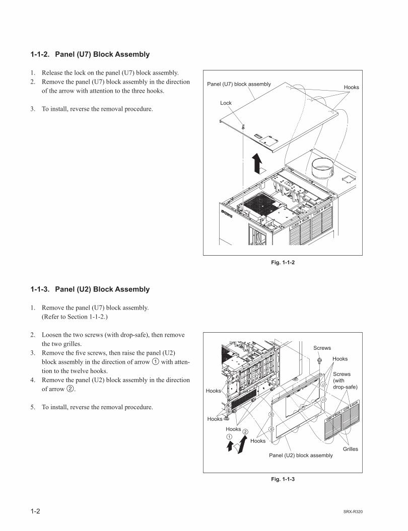
1-1-2. Panel (U7) Block Assembly
1. Release the lock on the panel (U7) block assembly.2. Remove the panel (U7) block assembly in the direction
of the arrow with attention to the three hooks.
3. To install, reverse the removal procedure.
1-1-3. Panel (U2) Block Assembly
1. Remove the panel (U7) block assembly. (Refer to Section 1-1-2.)
2. Loosen the two screws (with drop-safe), then remove the two grilles.
3. Remove the fi ve screws, then raise the panel (U2) block assembly in the direction of arrow with atten-tion to the twelve hooks.
4. Remove the panel (U2) block assembly in the direction of arrow .
5. To install, reverse the removal procedure.

1-3SRX-R320
Panel (U3)
Screws
Panel (U6) Hooks
Hooks
Hooks
Hooks
Hooks
Screws
Fig. 1-1-4
Fig. 1-1-5
1-1-4. Panel (U3)
1. Remove the panel (U7) block assembly. (Refer to Section 1-1-2.)2. Remove the panel (U2) block assembly. (Refer to Section 1-1-3.)
3. Remove the three screws, then remove the panel (U3) in the direction of the arrow.
4. To install, reverse the removal procedure.
1-1-5. Panel (U6)
1. Remove the panel (U7) block assembly. (Refer to Section 1-1-2.)
2. Remove the fi ve screws, then raise the panel (U6) in the direction of arrow with attention to the eleven hooks.
3. Remove the panel (U6) in the direction of arrow .
4. To install, reverse the removal procedure.

1-4 SRX-R320
Panel (U5)Screws
Panel (U1B)
Screws
Screws
Fig. 1-1-6
Fig. 1-1-7
1-1-6. Panel (U5)
1. Remove the panel (U7) block assembly. (Refer to Section 1-1-2.)2. Remove the panel (U6). (Refer to Section 1-1-5.)
3. Remove the three screws, then remove the panel (U5) in the direction of arrow.
4. To install, reverse the removal procedure.
1-1-7. Panel (U1B)
1. Remove the panel (U7) block assembly. (Refer to Section 1-1-2.)2. Remove the panel (U2) block assembly. (Refer to Section 1-1-3.)3. Remove the panel (U6). (Refer to Section 1-1-5.)
4. Remove the six screws, then lower the panel (U1B) in the direction of arrow .
5. Remove the panel (U1B) in the direction of arrow .
6. To install, reverse the removal procedure.

1-5SRX-R320
Panel (U1)
Screws Screws
Screws Screws
Fig. 1-1-8
1-1-8. Panel (U1)
1. Remove the panel (U7) block assembly. (Refer to Section 1-1-2.)2. Remove the panel (U2) block assembly. (Refer to Section 1-1-3.)3. Remove the panel (U6). (Refer to Section 1-1-5.)4. Remove the panel (U1B). (Refer to Section 1-1-7.)
5. Remove the eight screws, then remove the panel (U1) in the direction of arrow.
6. To install, reverse the removal procedure.

1-6 SRX-R320
Panel (U4) block assembly
Panel (U4) block assembly
Lock
Hinge portions
About80 degrees
Fig. 1-1-9
1-1-9. Panel (U4) Block Assembly
1. Release the lock on the panel (U4) block assembly.2. Open the panel (U4) block assembly at an angle of
about eighty degrees.3. Raise to remove the panel (U4) block assembly from
the two hinge portions.
4. To install, reverse the removal procedure.

1-7SRX-R320
Panel (U4B)HooksScrews
Screws
Fig. 1-1-10
1-1-10. Panel (U4B)
1. Remove the panel (U7) block assembly. (Refer to Section 1-1-2.)2. Remove the panel (U2) block assembly. (Refer to Section 1-1-3.)3. Remove the panel (U3). (Refer to Section 1-1-4.)4. Remove the panel (U6). (Refer to Section 1-1-5.)5. Remove the panel (U5). (Refer to Section 1-1-6.)6. Open the panel (U4) block assembly. (Refer to steps 1 and 2 in Section 1-1-9.)
7. Remove the four screws, then remove the panel (U4B) in the direction of arrow with attention to the two hooks.
8. To install, reverse the removal procedure.

1-8 SRX-R320
Screws
Screws
Screws
Panel (U8)
STL cover
Fig. 1-1-11
1-1-11. Panel (U8)
1. Remove the panel (U7) block assembly. (Refer to Section 1-1-2.)2. Remove the panel (U2) block assembly. (Refer to Section 1-1-3.)3. Remove the panel (U3). (Refer to Section 1-1-4.)4. Remove the panel (U6). (Refer to Section 1-1-5.)5. Remove the panel (U5). (Refer to Section 1-1-6.)
6. Remove the two screws, then remove the STL cover.7. Remove the eight screws, then remove the panel (U8).
8. To install, reverse the removal procedure.

1-9SRX-R320
Nut
Adjuster
Adjuster pipe
Fig. 1-2a
1-2. Tilt Angle Adjustment
nFor further adjustment, “2-6. Field Angle Adjustment” is required.
In the case of tilt angle under 5 degrees:Adjust the tilt angle using the adjuster in the lower portion of this unit.
1. Loosen the nut.2. Adjust the tilt angle by rotating the adjuster in the
lower portion of this unit.3. Secure the adjuster by tightening the nut to the adjuster
pipe side.

1-10 SRX-R320
M8bolts
Jack
Jack
M8 bolts
Holes
Adjuster pipe assembly
Adjuster pipe assembly
Jack
Frame
nWhen setting the jack, pay attention to the holes on the bottom of flame.
Fig. 1-2b
In the case of tilt angle from 5 to 10 degrees:1. Remove the panel (U7) block assembly. (Refer to Section 1-1-2.)2. Remove the panel (U2) block assembly. (Refer to Section 1-1-3.)3. Remove the panel (U3). (Refer to Section 1-1-4.)4. Remove the panel (U6). (Refer to Section 1-1-5.)5. Remove the panel (U5). (Refer to Section 1-1-6.)
6. Set the tools such as jack at both sides of frame, then raise the rear portion of the main unit.
7. Remove the four M8 bolts.8. Move the adjuster pipe assembly downward and insert
the four M8 bolts into the four holes to secure it.9. Lower the jack and attach the panel (U5), panel (U6),
panel (U3), panel (U2) block assembly and panel (U7) block assembly.

1-11SRX-R320
Adjuster
Anchor BKT
Duct connection
8-inch duct
Fig. 1-2c
Fig. 1-3
In the case of fi xing this unit:This unit can be fi xed to the fl oor using the anchor BKT. When fi xing this unit, attach the anchor BKT to the adjust-er as shown in the illustration.
Part nameAnchor BKT (optionally available): 3-294-224-01
1-3. Installing the Duct
Attach the commercially available 8-inch duct to the duct connection of the panel (U8) of this unit.nWhen attaching the duct, be careful not to bend it so that the exhaust air fl ows smoothly.
External fan (exhaust air) air volume specifi cationThe following exhaust air volume is required for the 8-inch duct.Exhaust air volume: 450 to 550 ft3/min (12.7 to 15.6 m3/min)

1-12 SRX-R320
Bolts
Focus cableZoom cable
POTENTIO cable
Projection lens
Pins
Projectionlens
Notch Line
Tighten the bolts in the order from to .
Lens bracket
Fig. 1-4
1-4. Installing the Projection Lens
1. Attach the projection lens.2. Align the notch of lens bracket with the line of projec-
tion lens and tighten the supplied four bolts in the order from to .
3. Connect the three cables (focus, zoom and POTEN-TIO).
nDo not attach the lens cover before completing the lens adjustment. (Refer to Section 2-3.)

1-13SRX-R320
Hook
Holes
Convex portions
Hole
Hole
Convexportions
Lens cover
Lens cover
Lens cover
Hook
Hook
Lens cover
Hook
Hook
Hook
Fig. 1-5a
Fig. 1-5b
1-5. Installing the Lens Cover
1. Attach the lens cover in the direction of arrow with attention to the three hooks.
n The lens covers are same parts, so they can be attached
both upper and lower.
2. Attach the lens cover in the direction of arrow with attention to the three hooks.
n When attaching the lens cover, align the four convex
portions with the four holes.

1-14 SRX-R320
STL cover
Screws
Status light assembly
Harnesses
Harnesses
One-touch bush
Screws
Fig. 1-6a
Fig. 1-6b
1-6. Installing the Status Light Assembly
1. Open the panel (U4) block assembly. (Refer to steps 1 and 2 in Section 1-1-9.)
2. Remove the two screws, then remove the STL cover. n Store the removed STL cover.
3. Attach the one-touch bush (supplied with the unit) to the hole in the upper area of this unit.
4. Route the harnesses through the hole in the upper area of the unit, then connect the two harnesses of the status light assembly and the two harnesses of the unit.
n The tags are attached on the harnesses (4-pin). Connect them with the following combination of the
indication on the tag.
Status light side This unit side
LIGHT LIGHT(none) SW
5. Attach the status light assembly with the two screws.6. Close the panel (U4) block assembly.

1-15SRX-R320
M4screws
Rear side
TPC base
M3 screwsM3 screws
TPC bracket
Operating monitor Upper side
Fig. 1-7a
Fig. 1-7b
1-7. Installing the Touch Panel Adapter
nThe recommended operating monitor manufactured by ADVANTECH can be attached to the supplied touch panel adapter. For details, contact your local Sony Sales Offi ce/Service Center.
1. Attach the TPC base to the panel (U4B) with the six M4 screws.
2. Attach the TPC bracket to the operating monitor with the six M3 screws.

1-16 SRX-R320
TPC base
TPC bracket
Operating monitor
Angular adjustment hole
TPC base
Knob
Knob
TPC base
Fig. 1-7c
3. Pull the knob of the TPC base in the direction of the arrow , then fi x it by rotating in the direction of the arrow .
4. Attach the operating monitor to the TPC base as shown in the illustration.5. Align the knob with the angular adjustment hole, then return the knob to the original position in the
reverse order of step 3.
1-17SRX-R320
Adjuster
Protection suit
Arm cover
Hood
Face shield
Face shield
Glove
Arm cover
Glove
Fig. 1-8a
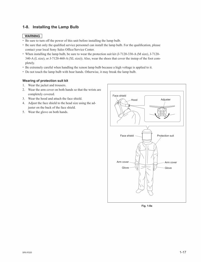
1-8. Installing the Lamp Bulb
w. Be sure to turn off the power of this unit before installing the lump bulb. . Be sure that only the qualifi ed service personnel can install the lamp bulb. For the qualifi cation, please
contact your local Sony Sales Offi ce/Service Center.. When installing the lamp bulb, be sure to wear the protection suit kit (J-7120-330-A (M size), J-7120-
340-A (L size), or J-7120-460-A (XL size)). Also, wear the shoes that cover the instep of the foot com-pletely.
. Be extremely careful when handling the xenon lamp bulb because a high voltage is applied to it.
. Do not touch the lamp bulb with bear hands. Otherwise, it may break the lamp bulb.
Wearing of protection suit kit1. Wear the jacket and trousers.2. Wear the arm cover on both hands so that the wrists are
completely covered.3. Wear the hood and attach the face shield.4. Adjust the face shield to the head size using the ad-
juster on the back of the face shield.5. Wear the glove on both hands.

1-18 SRX-R320
Screw
Anode harnessPortion A
Lamp bulb
Anode harness
Anode side
Screw
Fig. 1-8b
Fig. 1-8c
Procedure
m. Keep the serial code label affi xed on the Operating Instructions of the lamp bulb which is required for
installation.. Keep the materials such as packaging box, case, protection sheet because they are used when disposing
of the used lamp bulb.. As for the anode harness integrated lamp bulb, steps 1 and 2 are not required.
1. Loosen the screw and bend portion A of the anode harness.
2. Attach the anode harness to the anode side of the lamp bulb, then tighten the screw.
(Tightening torque: 1.2 N.m)

1-19SRX-R320
Cathode terminal
Hexagon socket set screw
Anode terminal Bolt
Screw(withdrop-safe)
Screw(with drop-safe)
Cold mirror assembly
Cold mirror assembly
Screws (with drop-safe)Maintenance cover
Panel (U4) block assembly
Fig. 1-8d
Fig. 1-8e
3. Open the panel (U4) block assembly. (Refer to steps 1 and 2 in Section 1-1-9.)4. Loosen the screw (with drop-safe), then rotate the cold
mirror assembly in the direction of the arrow.5. Loosen the fi ve screws (with drop-safe), then remove
the maintenance cover.
6. Remove the bolt from the anode terminal.7. Loosen the hexagon socket set screw of the cathode
terminal.

1-20 SRX-R320
Plastic cover
Lamp bulb
Protection sheet
Lamp bulb
Fig. 1-8g
Fig. 1-8f
8. Remove the plastic cover from the lamp bulb.
9. Remove the protection sheet from the lamp bulb.

1-21SRX-R320
Knob
Anodeholder
Lamp bulb
Portion A
Cathode terminal
Reflector portion
Fig. 1-8h
10. Loosen the knob, then move the anode holder in the direction of the arrow.
11. Insert portion A of the lamp into the cathode terminal. n When attaching the lamp bulb, be careful not to dam-
age the refl ector portion. Also, be careful not to dam-age the glass of lamp bulb. Otherwise, it may break the lamp bulb.
12. Hold the cathode side of the lamp bulb fi rmly and raise the anode side. Then, return the anode holder to the original position and tighten the knob.

1-22 SRX-R320
Cathode terminalHexagon socket set screw
Anode terminal
Bolt
Anode holder
Anode harness
Knob
Cathode terminalEnd face
Surface CLamp bulb
Anodeholder
Lamp bulb
Anodeharness
No clearance
Adjust by bending this portion.
Portion A
In the case of anode harness separated lamp bulb
Anodeholder
Lamp bulb
Anodeharness
In the case of anode harness integrated lamp bulb
Fig. 1-8i
13. Place the anode side of the lamp bulb on the anode holder.
14. Attach the anode harness to the anode terminal, then tighten the bolt. (Tightening torque: 1.5 N.m).
n After installing the anode harness separated lamp bulb,
if there is a clearance in portion A of the anode holder, adjust it by bending the anode harness so that there is no clearance between the anode holder and the lamp bulb.
15. Tighten the hexagon socket set screw of the cathode terminal.
(Tightening torque: 1.2 N.m) n Be sure that there is no clearance between the end face
of the cathode terminal and the surface C of the lamp bulb.
16. Attach the panel (U4) block assembly in the reverse order of steps 3 to 5.

1-23SRX-R320
Front panel
Screw(with drop-safe)
LMT-300
Screw(with drop-safe)
Fig. 1-9a
1-9. Installing LMT-300 and Connecting with the Unit
1. Remove the panel (U7) block assembly. (Refer to Section 1-1-2.)2. Remove the panel (U2) block assembly. (Refer to Section 1-1-3.)3. Remove the panel (U6). (Refer to Section 1-1-5.)4. Remove the panel (U1B). (Refer to Section 1-1-7.)
5. Loosen the two screws (with drop-safe), then remove the front panel from the LMT-300.

1-24 SRX-R320
Harness
STATUS LIGHTconnector
LMT-300B5 x 12
B5 x 12
SRX-R320Front panel
Screw(with drop-safe)
Screw(with drop-safe)
Fig. 1-9b
6. Install LMT-300 in this unit.7. Secure LMT-300 with the four installation screws (B5 x 12) supplied with LMT-300.8. Attach the HDD unit supplied with LMT-300. (Refer to LMT-300 Installation Manual.)9. Connect the harness of this unit to the STATUS LIGHT connector in the front panel.10. Attach the front panel. n Tighten the screws (with drop-safe). Tightening torque: 0.8 N.m

1-25SRX-R320
LMT duct (B)
LMT duct (A)
Screw
Screw
Screws
LMT duct (A)Power cord
Notch
Fig. 1-9c
11. Attach the power cord to LMT-300.12. Attach the LMT duct (A) with the screw. n When attaching the LMT duct (A), route the power
cord through the notch.13. Attach the LMT duct (B) with the three screws.

1-26 SRX-R320
LMT-300
Shield case assembly (1)INPUT-C A
Networkconnector
CN-3225board
INPUT-C B
CSS PROJECTOR OUTPUT B
PROJECTOR OUTPUT APRJ CTRL
Fig. 1-9d
14. Connect INPUT-C A of the unit with PROJECTOR OUTPUT A of LMT-300 and INPUT-C B with PRO-JECTOR OUTPUT B using the supplied connection codes.
15. Connect the network connector of this unit with the PRJ CTRL connector of LMT-300 using the supplied LAN cable.
16. Connect the connector (CN6) on the CN-3225 board of this unit with the CSS connector of LMT-300 using the supplied CSS cable.
17. Attach the panel (U1B) in the reverse order of step 4.18. Attach the panel (U6) in the reverse order of step 3.19. Attach the panel (U2) block assembly in the reverse
order of step 2.20. Attach the panel (U7) block assembly in the reverse
order of step 1.

1-27SRX-R320
LKRI-003
B3 x 8Finger holder (HIF)
Panel (HIF-44)
LKRI-003
B3 x 8
Fixed plate (HIF) 320
Handle
Handle
Fig. 1-10a
Fig. 1-10b
1-10. Installing the Optional Board to INPUT A and INPUT B
For both INPUT A and INPUT B slots, the optional board, LKRI-003 or LKRI-005 can be installed.The installing procedure for each slot is same.nFor INPUT A slot, LKRI-005 is installed before shipment. Replace it as necessary.
Parts information
. Fixed Plate (HIF) 320: 4-159-161-01 (For LKRI-003)
. Fixed Plate (DIF) 320: 4-159-162-01 (For LKRI-005)
. Handle: 3-172-089-01 (Using 2 pcs)
Procedure (LKRI-003)
1. Remove the six screws, then remove the panel (HIF-44) and fi nger holder (HIF).
2. Attach the fi xed plate (HIF) 320 using the six screws removed in step 1.
3. Attach the two handles to the fi xed plate (HIF) 320.

1-28 SRX-R320
INPUT B
LKRI-003
PSW4 x 10
Panel cover (IF)
PSW4 x 10
PSW4 x 10
Panel cover (IF)
Blank panel
Fig. 1-10c
Fig. 1-10d
4. Remove the two screws, then remove the blank panel. n Store the removed blank panel.5. Remove the ten screws, then remove the panel cover
(IF).
6. Insert the LKRI-003 board into INPUT B slot, and connect it securely.
7. Attach the panel cover (IF) using the twelve screws.

1-29SRX-R320
LKRI-005
B3 x 8Finger holder (DIF)
Panel (DIF-188)
LKRI-005
B3 x 8
Fixed plate (DIF) 320
Handle
Handle
PSW4 x 10
PSW4 x 10
Panel cover (IF)
Blank panel
Fig. 1-10e
Fig. 1-10f
Fig. 1-10g
Procedure (LKRI-005)
1. Remove the two screws, then remove the panel (DIF-188) and fi nger holder (DIF).
2. Attach the fi xed plate (DIF) 320 using the two screws removed in step 1.
3. Attach the two handles to the fi xed plate (DIF) 320.
4. Remove the two screws, then remove the blank panel. n Store the removed blank panel.5. Remove the ten screws, then remove the panel cover
(IF).

1-30 SRX-R320
INPUT B
LKRI-005
PSW4 x 10
Panel cover (IF)
Fig. 1-10h
6. Insert the LKRI-005 board into INPUT B slot, and connect it securely.
7. Attach the panel cover (IF) using the twelve screws.

1-31SRX-R320
Fig. 1-10i
SRW-5000HD DIGITAL VIDEO CASSETTE RECORDER
LKRI-003
To HD-SDI output terminal
HD-SDI connecting cable (optionally available)
To IN terminal
HDCAM recorder/player, etc.
Connection with each equipment
m. Connect each equipment with the power turned off state.. Use the connecting cables applicable to each terminal.. Insert the plug securely. Incomplete connection may cause an image trouble. When disconnecting the plug, be sure to hold the plug with your hand.. Refer to the Operating Instructions of the equipment to be connected.
In case of LKRI-003
InputBNC type (2)HD-SDI: Serial digital (1.485 Gbps) Compliant to SMPTE-292M/ITU-R,
BT709/BTA-S004Dual-link HD-SDI: Serial digital (1.485 Gbps) Compliant to SMPTE-372MDC-SDI: Serial digital (1.485 Gbps) Compliant to 23.98 PsF, 24 PsF, 24P
OutputBNC type (2)Loop-through output
Quantization characteristics10 bits/sampling

1-32 SRX-R320
LKRI-005
To DVI-D terminal
To DVI output terminal
DVI-D cable (optionally available)
To AUX terminal
Personal computer
Fig. 1-10j
17 18 19 20 21 22 23 249 10 11 12 13 14 15 161 2 3 4 5 6 7 8
In case of LKRI-005
m. For INPUT A slot, LKRI-005 is installed by default. However, LKRI-003 can be installed.. When using a long cable, the image may not be displayed properly due to the signal attenuation.. When the 10 bit single mode is selected, the DVI cable applicable to Dual-link is required.
1. Connect the commercially available DVI cable to the terminal according to the input signal.
Input signal Used terminal
During normal operationDVI1.0 compliantSignal level: Full Range
DVI-D terminal
10 bit signal of its own specifi cationDuring input (10 bit twin mode)Signal level: Full Range
DVI-D terminal and AUX terminal
10 bit signal of its own specifi cationDuring input (10 bit single mode)Signal level: Full Range
DVI-D terminal
Used during signal input of DTV standardDVI1.0 compliantSignal level: Limited Range
DVI-D terminal
10 bit signal of its own specifi cationDuring input (10 bit twin mode)Signal level: Limited Range
DVI-D terminal and AUX terminal
10 bit signal of its own specifi cationDuring input (10 bit single mode)Signal level: Limited Range
DVI-D terminal
Pin location
DVI-D terminal, AUX terminal
Pin No. Signal name Pin No. Signal name
1 DATA2_ 13 DATA3+
2 DATA2+ 14 +5 V
3 GND 15 DDC_GND
4 DATA4_ 16 HOTPLUG_DET
5 DATA4+ 17 DATA0_
6 DDC_SCL 18 DATA0+
7 DDC_SDA 19 GND
8 NC 20 DATA5_
9 DATA1_ 21 DATA5+
10 DATA1+ 22 GND
11 GND 23 CLK+
12 DATA3_ 24 CLK_

1-33SRX-R320
87
65
43
21
1514
1312
1110
9
8 7 6 5 4 3 2 1
15 14 13 12 11 10 9
Interlockterminal
Shield case assembly (1)
1-11. Interlock Terminal
Pin location
Interlock terminal
1. Interlock FunctionThe SRX-R320 interlock function is enabled by making the two pins of the interlock terminal open or short. The following two patterns can be used for the interlock function in the applicable serial.
Pattern 1Normal: OpenInterlock: Short
Open/short between pin 4 and pin 5

1-34 SRX-R320
87
65
43
21
1514
1312
1110
9
Pattern 2Normal: ShortInterlock: Open
Open/short between pin 5 and pin 6 with the pin 3 and pin 4 shorted state
2. External fan control functionThis unit mounted a power interlocking relay for external fan control.The transfer contact type relay controls between normally-open and normally-closed by selecting the pins.nThe relay for external fan control is used for switching the ON/OFF control signals for fan. The driving current of fan is not switched.
PIN assign
Pin Signal name Function
Pin 7 RELAY1_A make contactPin 8 RELAY1_B break contactPin 9 RELAY1_C transfer contact
Operation table
Operation terminal Operating state
STANDBY POWER ON
RELAY1_C 5 RELAY1_A open short
RELAY1_C 5 RELAY1_B short open
Contact specifi cationContact rated voltage/current: 25 V DC/500 mA
1-35SRX-R320
External device
Hole
Front side
Fig. 1-12
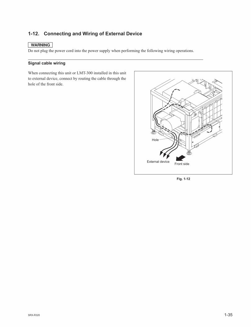
1-12. Connecting and Wiring of External Device
wDo not plug the power cord into the power supply when performing the following wiring operations.
Signal cable wiring
When connecting this unit or LMT-300 installed in this unit to external device, connect by routing the cable through the hole of the front side.

1-36 SRX-R320
1-13. Connecting the Power Cord
Use the 3-core power cord that satisfy AWG 8, 250 V rated and 40 A rated. Connect the power cord to the AC IN terminal block on the rear side of this unit, referring the following procedure.
w. Connection of the main power and the electric wiring work should be done by qualifi ed electricians
only.. Do not plug the power cord into the power supply before completing all of the following connecting op-
erations.
1. Remove the two screws.2. Remove the terminal block cover with attention to the
two hooks.
3. Remove the screw, then remove the cable clamp.4. Remove the screw, then remove the ground terminal.
Screws
Hooks
Terminal block cover
Screw
Screw
Cable clamp
Ground terminal
Fig. 1-13a
Fig. 1-13b

1-37SRX-R320
Ground wire
Ground terminalPack by soldering
Screw
Screws
Ground terminal
Cable clamp
Screw
Fig. 1-13c
Fig. 1-13d
5. Pack by soldering the end of the ground wire.6. Attach the ground terminal removed in step 4 to the
ground wire, then fi x it with the screw.
7. Route the cable through the lower hole of the terminal block, then fi x each terminal by screw.
8. Fix the cable with the cable clamp and screw.9. Attach the terminal block cover.

1-38 SRX-R320
1-14. Dimensions
Front
Left
Exhaust
(Barycentricposition)
(Bar
ycen
tric
posit
ion)

1-39SRX-R320
Top
Right
Bottom
Rear
Exhaust
Intake
Signal cable
(For the unit fixing)
AC power cableIntake
ExhaustIntake
Intake
Intake*(Optional lens)
*LKRL LIST
(Barycentric position)
(Bar
ycen
tric
posit
ion)
(Barycentric position)
Refer to List
(Bar
ycen
tric
posi
tion)
Panel for lamp replacing
Unit: mm


2-1SRX-R320
Section 2Adjustment
1. Install an SRX Controller in an adjusting personal computer. (Refer to Section 2-1.)
4. Perform illumination range adjustment and registration adjustment. (Perform these adjustments as required.) (Refer to Section 2-4.)
5. Perform the γ adjustment and uniformity adjustment using the PJ COLOR ADJUSTMENT TOOL. (Refer to Technical Manual of SRX-R220.)
6. Set the illuminance of a screen and perform color characteristic tone correction (CSC adjustment). (Refer to Section 2-5.)
2. Perform the optical axis adjustment of a lamp. (Perform calibration.) (Refer to Section 2-2.)
3. Adjust a lens. (Refer to Section 2-3.)
8. Set function memory. (Refer to Section 2-7.)
7. Adjust the field angle. (Refer to Section 2-6.)
Adjustment is performed using an SRX Controller. Refer to Section 2-8. for how to use an SRX Controller.Perform adjustment in the procedure below.

2-2 SRX-R320
Fig. 2-1-1a
2-1. Installation of SRX Controller
2-1-1. Installation
This unit can be operated from PC when the SRX Controller is installed in a personal computer (PC).nFor obtaining of the SRX Controller, please contact your local Sony Sales Offi ce/Service Center.
Preparation
. PC CPU: Intel Pentium M 1.6 GHz or more, and OS-recommended RAM capacity: 256 MB or more (512 MB or more recommended), and OS-recommended Communication: RS-232C (10BASE-T/100BASE-T) Graphics mode: XGA (1024 x 768) or higher HDD: Built-in Drive, having an empty capacity of 10 MB or more CD-ROM drive: Eight times normal speed or faster OS: Microsoft Windows XP Professional SP2 (except for x64 Edition). Cable COM: RS-232C cross cable
Installation
1. Connect each equipment referring to Section 2-1-2.2. Turn on the power of PC.3. Copy an SRX Controller to any place of PC.4. Double-click “setup.exe”.

2-3SRX-R320
Fig. 2-1-1b
Fig. 2-1-1c
Fig. 2-1-1d
5. Click the [Next] button.
6. Confi rm the contents of the license agreement and click the radio button for “I accept the terms in the license agreement”. Click the [Next] button.
7. Select the folder in which an SRX Controller is installed. Click the [Next] button if there is no problem in the displayed folder. To change the folder to save an SRX Controller, click the [Change...] button and select the desired
folder.

2-4 SRX-R320
Fig. 2-1-1e
Connection cable (Inter-link cross cable)
To RS-232C terminal
Personal computer
To RS-232C terminal
Fig. 2-1-2
8. Click the [Install] button. Installation is started.9. Check that the window below is displayed. (Installation is completed.) n Click the check box for “Launch SRX Controller specialized for DC Projector series” when directly
starting an SRX Controller in this case.
10. Click the [Finish] button. The shortcut of an SRX Controller is displayed on the desktop window.
2-1-2. Connection
nWhen performing the adjustment using the RS-232C terminal, connect nothing to the NETWORK termi-nal of the main unit.

2-5SRX-R320
Click this radio button.
Select “User”, “Maintenance” or “Installer”.
Enter the password.
[OK] button
Enter the COM port No. to be used.
Fig. 2-1-3a
2-1-3. Startup and Initialization of SRX Controller
Procedure
1. Connect each equipment according to Section 2-1-2.2. Turn on the power switch on the rear of this unit so that it enters the standby state. (Refer to step 1 of “2-1-4. Startup of This Unit”.)3. Double-click “Start SRX Controller.exe” on the desktop window.4. Click the “COM” radio button from the “Connection” menu.
. COM selection: Enter the COM port No. to be used.5. Select the adjustment menu (Login) to be used in a “Login” menu. The three adjustment menus
below are available.. User: Can check the signal input to this unit or adjust an image.. Maintenance: Can set a lamp or adjust an image in details.. Installer: Can check and change the contents of setting during installation of login informa-
tion or a network.6. Enter the passwords and click the [OK] button.
. User: A password is not required.
. Maintenance: service
. Installation: setting n Enter the passwords of “Maintenance” and “Installer” using lower-case characters.

2-6 SRX-R320
Fig. 2-1-3b
Fig. 2-1-3c
Fig. 2-1-3d
nWindow of each adjustment menu
Window example (Login by “User”: FUNCTION MEMORY window)
Window example (Login by “Maintenance”: MAINTENANCE window)
Window example (Login by “Installer”: INSTALLATION window)

2-7SRX-R320
Power switch
ON
“INSTALLATION” tab [ON] button
Fig. 2-1-3e
Fig. 2-1-4a
7. Click the INSTALLATION tab. The INSTALLATION window is displayed.
8. Set the items in “Internet Setting” and “Time Setting” menus. (Refer to “5. INSTALLATION window” in Section 2-8-3.)9. Enter the serial code of the lamp bulb to be installed. (Refer to steps 1 to 4 in Section 2-2.)
2-1-4. Startup of This Unit
Procedure
1. Turn on the power switch on the rear of this unit. (Standby state)

2-8 SRX-R320
[ON] button
Fig. 2-1-4b
“MAINTENANCE” tab [RESET] button
Fig. 2-2a
2. Start the SRX Controller. (Refer to Section 2-1-3.) n This procedure is common in the adjustment menu of “User”, “Maintenance” and “Installer”.3. Click the [ON] button of POWER. The startup of this unit is completed.
2-2. Optical Axis Adjustment of Lamp
Procedure
1. Be sure to click the “MAINTENANCE” tab in the standby state.2. Click the [RESET] button in a “LAMP TIMER RESET” menu.

2-9SRX-R320
Enter the serial code. [CHECK] button [ON] button
[CLOSE] button
Fig. 2-2b
Fig. 2-2c
3. Enter the serial code described in the Operating Instructions of a lamp bulb in the “Serial Code” box and click the [CHECK] button.
m. Be sure to perform in the standby state. (Refer to step 1 in Section 2-1-4.). Enter the serial code with the space not put.
4. Click the [CLOSE] button and close the LAMP INFORMATION window.5. Click the [ON] button of POWER.
6. Click the “FUNCTION MEMORY” tab.7. Set the lamp power to 100% in the “LAMP POWER” menu to project an image in 100% black. (No signal condition)

2-10 SRX-R320
X-axis direction adjusting screw
Y-axis direction adjusting screw
Fig. 2-2d
Status message dispaly
START STOP
SAVE_ +
[SAVE]button[+], [_] button[START] button
Fig. 2-2e
Fig. 2-2f
8. Click the [START] button in a “Lamp Adjust” menu on the “LAMP INFORMATION” window.
The unit enters the lamp adjustment mode.9. Wait for fi ve minutes.10. When the unit enters the lamp adjustment mode, the
value of the internal luminance sensor is displayed on the status message display.
Adjust “Z Axis Adjust” using the [+]/[_] button so that the luminance value becomes maximum.
n A lamp bulb is not installed when this unit is shipped
from the factory. Therefore, an “F34/F35 ADJUST-MENT ERROR” message may be displayed on the status message display and SRX Controller at the rear of this unit before this adjustment is performed. This message disappears when you press the [Save] button after Z axis adjustment.
11. In the same way, adjust the X-axis and Y-axis direction adjusting screws so that the value of the internal lumi-nance sensor becomes maximum.
12. Adjust “Z Axis Adjust” again using the [+]/[_] button so that the value of the internal luminance sensor becomes maximum.
13. Click the [Save] button.14. Age this unit for fi ve minutes.15. Click the [CALIBRATE] button. n Click the [CALIBRATE] button after at least 10
minutes turning on the lamp.

2-11SRX-R320
Projectionlens
Tighten the bolts in the order of to .
Lens bracket
Lens bracket shield
Flat screw driver
Bolts
Bolts
Projection lens
Fig. 2-3a
Luminance deterioration correction functionThis unit has a function that makes the output illuminance constant using a sensor inside equipment. By pressing the [CALIBRATE] button, this function provides an internal sensor and lamp power output value in the internal table and controls a lamp power output value so that it becomes the luminance value set for each function memory. To maintain the precision of an output value, press the [CALIBRATE] button about once a week.
nThis function is enabled when Lamp Control Mode is set to Luminance.It is set to “Lamp Power” in the initial setting.(Refer to “5. INSTALLATION window” in “2-8-3. Function of Each Window”.)
2-3. Lens Adjustment (H Shift, V Shift, Zoom, and Focus Adjustments)
nFor further adjustment, “2-6. Field Angle Adjustment” is required.
Procedure
1. Project a test pattern on the MAINTENANCE window.2. Loosen the four bolts securing the projection lens.
Insert the fl at screwdriver between the lens bracket and the lens bracket shield and move the projection lens from side to side to adjust the horizontal position (H shift) of the image.
3. After H shift adjustment is completed, tighten the four screws loosened in step 2.

2-12 SRX-R320
Control knob
Adjustment lid
Projection lens
Fig. 2-3b
Effective area of lens
Effective area of lens
Center of lens
Image
Image
Fig. 2-3c
4. Open the adjustment lid.5. Turn the control knob of this unit to move the lens up
and down for adjusting the vertical position (V shift) of an image.
6. Adjust the zoom and focus using the [+]/[_] buttons in the “Lens Control” menu on the FUNCTION MEMO-RY window. (Refer to “2. FUNCTION MEMORY window” in “2-8-3. Function of Each Window”.)
nSet the V shift amount within 1/2 screen. If it exceeds 1/2 screen, the zoom is changed, the image position may not be positioned at same place.
Check if the V shift amount exceeds 1/2 screen in the following procedure.When the V shift amount exceeds 1/2 screen, perform the adjustment.
In the case that the V shift is lowered.
How to Check. When the image is expanded by zoom, the upper end of image position is lowered.
2-13SRX-R320
Effective area of lens
Effective area of lens
Center of lens
ImageImage
Fig. 2-3d
How to Adjust. Adjust the V shift so that the upper end of image position remains unchanged when the image is expand-
ed by zoom.
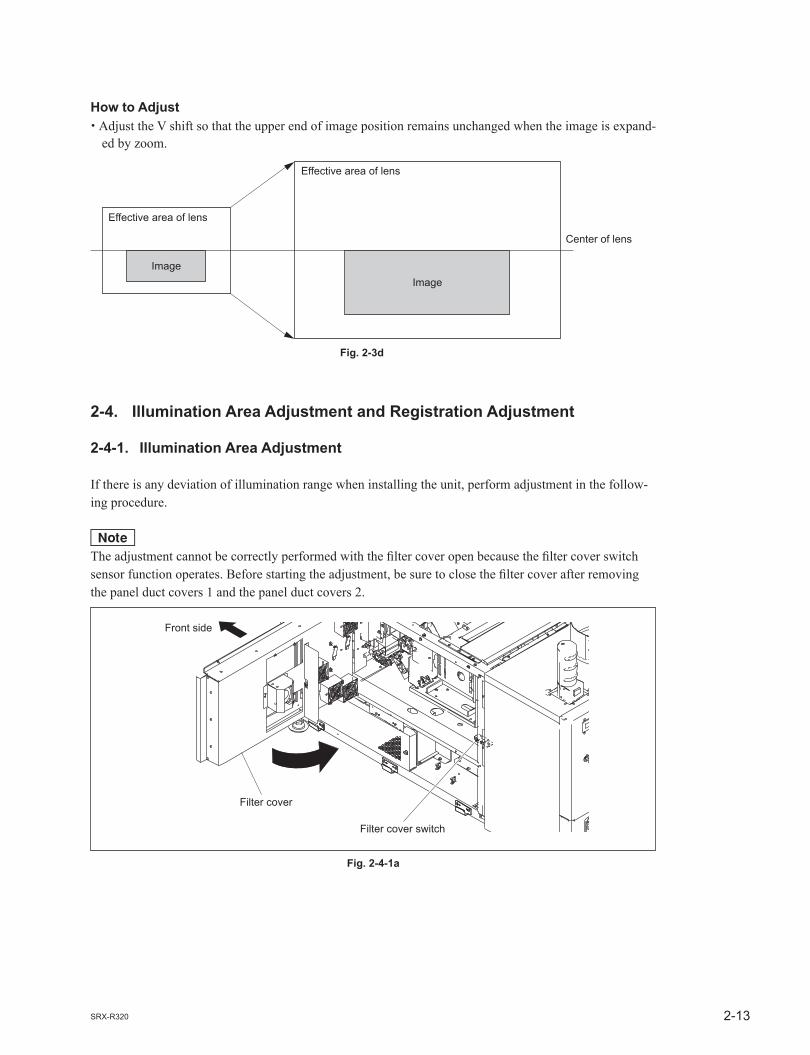
2-4. Illumination Area Adjustment and Registration Adjustment
2-4-1. Illumination Area Adjustment
If there is any deviation of illumination range when installing the unit, perform adjustment in the follow-ing procedure.
nThe adjustment cannot be correctly performed with the fi lter cover open because the fi lter cover switch sensor function operates. Before starting the adjustment, be sure to close the fi lter cover after removing the panel duct covers 1 and the panel duct covers 2.
Filter cover
Front side
Filter cover switch
Fig. 2-4-1a

2-14 SRX-R320
Procedure
1. Remove the panel (U7) block assembly. (Refer to Section 1-1-2.)2. Remove the panel (U2) block assembly. (Refer to Section 1-1-3.)
3. Remove the fi lter.4. Remove the fi ve screws.
Fig. 2-4-1b
Filter (center portion)
ScrewsFront side

2-15SRX-R320
5. Open the fi lter cover in the direction of the arrow.6. Remove the two screws, then remove the panel duct cover 2 (upper).7. Remove the two screws, then remove the panel duct cover 1 (upper).8. Remove the panel duct cover 2 (lower) and the panel duct cover 1 (lower) in the same procedure as
steps 6 and 7.9. Close the fi lter cover, then secure it with the screw.
Fig. 2-4-1c
Panel duct cover 2 (upper)
Panel duct cover 2 (lower)
Filter cover
Panel duct cover 1 (upper)
Screws
Screws
Panel duct cover 1 (lower)
Front side
Filter coverSecure with the screw.

2-16 SRX-R320
10. Start the SRX Controller. (Refer to Section 2-1-3.)11. Click the “FUNCTION MEMORY” tab.
FUNCTION MEMORY window
MAINTENANCE window
“TEST PATTERN” menuFig. 2-4-1e
“LENS CONTROL”menu
“LAMP POWER” menuFig. 2-4-1d
2-17SRX-R320
Portion A
Portion B
Adjusts the left and right of the white image by parallel movement. Adjusts the top and bottom of the white image by rotational movement.
Fig. 2-4-1f
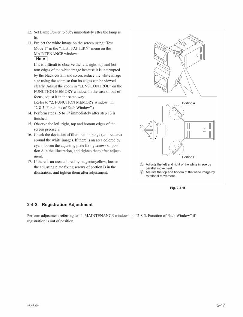
12. Set Lamp Power to 50% immediately after the lamp is lit.
13. Project the white image on the screen using “Test Mode 1” in the “TEST PATTERN” menu on the MAINTENANCE window.
n If it is diffi cult to observe the left, right, top and bot-
tom edges of the white image because it is interrupted by the black curtain and so on, reduce the white image size using the zoom so that its edges can be viewed clearly. Adjust the zoom in “LENS CONTROL” on the FUNCTION MEMORY window. In the case of out-of- focus, adjust it in the same way.
(Refer to “2. FUNCTION MEMORY window” in “2-8-3. Functions of Each Window”.)
14. Perform steps 15 to 17 immediately after step 13 is fi nished.
15. Observe the left, right, top and bottom edges of the screen precisely.
16. Check the deviation of illumination range (colored area around the white image). If there is an area colored by cyan, loosen the adjusting plate fi xing screws of por-tion A in the illustration, and tighten them after adjust-ment.
17. If there is an area colored by magenta/yellow, loosen the adjusting plate fi xing screws of portion B in the illustration, and tighten them after adjustment.
2-4-2. Registration Adjustment
Perform adjustment referring to “4. MAINTENANCE window” in “2-8-3. Function of Each Window” if registration is out of position.

2-18 SRX-R320
“INPUT CONTROL”menu
Fig. 2-5a
“COLOR SPACE CONVERTER”menu
[ADJUST] button
Fig. 2-5b
2-5. Screen Illuminance Setting and Color Space Conversion (CSC Adjustment)
Before setting function memory, set the illuminance on the screen and correct the color space, with the unit installed.
Color space converterThe color space converter can correct the color characteristics of this unit (709, Virtual White and DCDM) for each color reproduction range.
Correction of color space “709”
Procedure
1. Display the FUNCTION MEMORY window of the SRX Controller. (Refer to Section 2-1-3.)2. Click the radio button of “Input A” in the INPUT CONTROL menu.
3. Display the MAINTENANCE window. (Refer to Section 2-1-3.)

2-19SRX-R320
4. Click the [ADJUST] button in the “COLOR SPACE CONVERTER” menu. The COLOR SPACE window is displayed.
5. Select “Gray 10” in “TEST PATTERN SELECT” menu. A test pattern of Gray 10 is displayed.6. Click the “FUNCTION MEMORY” tab. The FUNCTION MEMORY window is displayed.7. Adjust using the [+]/[_] button of the lamp power so that the illuminance on the screen is approxi-
mately 16 ft-L (the illuminance to be set + approximately 2 ft-L).8. Select “6500” in “Color Temp” of the “COLOR” menu. n When the item is not a available, input a video signal.9. Select “709” in “Color Space” of “COLOR” menu. n When the item is not a available, input a video signal.
n Each value is automatically displayed in the “Target Color Gamut” column of the “COLOR SPACE” window on the MAINTENANCE tab.
Moreover, reference white point targets “x” and “y” and luminance level “Y” are projected automatically.
“TEST PATTERN SELECT” menuFig. 2-5c
“LAMP POWER” menu
“COLOR” menuFig. 2-5d

2-20 SRX-R320
10. Click the “MAINTENANCE” tab.11. Click the [ADJUST] button in a “COLOR SPACE CONVERTER” menu. The “COLOR SPACE” window is displayed.
12. Select “709” in the “COLOR SPACE” menu. n When “COLOR SPACE” is not available, input a video signal.13. Click the [RESET] button. A color space function is set to OFF, and the characteristics of this unit can be measured.14. Project Green-1, Blue-1, and Red-1, respectively in the “TEST PATTERN SELECT” menu and
measure “x”, “y”, and luminance level “Y”.15. Select “Gray 8” according to the reference white point. A test pattern of Gray 8 is displayed.16. Measure “x”, “y” and luminance level “Y”.17. Enter the measurement result in step 14 into the “Input Color Measurement” column.18. Click the [CALC] button.19. Confi rm that the differences of all numeric values are less than ?0.002. n When there is an item in which the differences of the numeric value is ?0.002 or more, repeat the
steps 14 to 18.20. Click the [APPLY] button.21. Return the setting before adjusting.
nWhen the CSC adjustment is performed, the luminance is lowered by approximately 2 ft-L. Therefore, adjust the lamp power in the “LAMP POWER” menu to obtain the required luminance again.
“Input Color Measurement” column
[RESET]button
[CALC]button
[APPLY]button“COLOR SPACE” menu
“TEST PATTERN SELECT” menu
Fig. 2-5e
2-21SRX-R320
Fig. 2-5f
“COLOR SPACE CONVERTER”menu
[ADJUST] button
“Input Color Measurement” column
[RESET]button
[CALC]button
[APPLY]button
“TEST PATTERN SELECT” menu
[TARGET|RECALL]button
“COLOR SPACE” menu
Fig. 2-5g
Adjustment of color space “Virtual White”The adjustment can be performed in the following two methods.
Procedure
Adjustment using internal test patternThe adjustment can be performed using the internal test patterns; “Red-1”, “Green-1”, “Blue-1” and “Gray-8”.
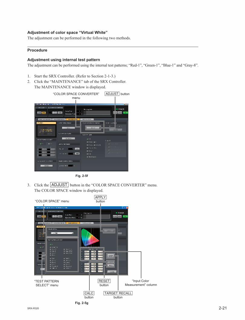
1. Start the SRX Controller. (Refer to Section 2-1-3.)2. Click the “MAINTENANCE” tab of the SRX Controller. The MAINTENANCE window is displayed.
3. Click the [ADJUST] button in the “COLOR SPACE CONVERTER” menu. The COLOR SPACE window is displayed.

2-22 SRX-R320
4. Select the “Gray-10” in the “TEST PATTERN SELECT” menu.5. Measure the luminance of screen and adjust the lamp power in the “LAMP POWER” menu on the
FUNCTION MEMORY window so that the luminance is 16 ft-L. After adjustment, the luminance is lowered by approximately 2 ft-L.6. Select “Virtual White” in the “COLOR SPACE” menu. n When “COLOR SPACE” is not available, input a video signal.7. Check the W values of “Target Color Gamut” is x = 0.319, y = 0.3338.8. When the W values are mismatch, click the [TARGET|RECALL] button.9. Click the [RESET] button fi rst, and then click the [APPLY] button.10. Select “Red-1”, “Green-1”, “Blue-1” and “Gray-8” respectively in the “TEST PATTERN SELECT”
menu. Then, measure x and y values respectively.11. Enter the x and y values in Input Color Measurement in the “COLOR SPACE” menu.12. Click the [CALC] button fi rst, and then click the [APPLY] button on the “COLOR SPACE” window.13. Select “Red-1”, “Green-1”, “Blue-1” and “Gray-8” respectively in the “TEST PATTERN SELECT”
menu. Then, measure the x and y values respectively and compare the results with the following specifi cations within an error range of 0.006.
x y
Red-1 0.680 0.320Green-1 0.265 0.690Blue-1 0.150 0.060Gray-8 0.319 0.3338
n If the specifi cations are not satisfi ed, perform steps 4, 5, and 9 to 12 again.14. Select the “Gray-10” in the “TEST PATTERN SELECT” menu.15. Click the “FUNCTION MEMORY” tab. The FUNCTION MEMORY window is displayed.16. Adjust the lamp power in the “LAMP POWER” menu so that the luminance is 14 ft-L.
nIn this procedure, the luminance is not correctly 14 ft-L. When the correct luminance is required, input “Gray 10” of the SONY color patch by LMT-300, and adjust the lamp power.

2-23SRX-R320
“INPUT CONTROL”menu
“PICTURE CONTROL”menu
“LAMP POWER” menuFig. 2-5h
Adjustment using “Sony Color Patch”1. Copy the Sony color patch fi les (DPPJ07-080_1.zip to DPPJ07-080_4.zip) in PC. n For obtaining, please contact your local Sony Sales Offi ce/Service Center.2. Create the “Sony_Color_Patch” folder and move all fi les obtained by decompressing the zip fi le to
the “Sony_Color_Patch” folder. (The fi les having the extension of .xml and .mxf)3. Import it in the same way as the normal DCP contents. 4. Start the SRX Controller and the Screen Management Controller.5. Click the “FUNCTION MEMORY” tab of the SRX Controller. The FUNCTION MEMORY window is displayed.

2-24 SRX-R320
“COLOR SPACE CONVERTER”menu
[ADJUST] button
Fig. 2-5i
6. Click the “Input C” (LMT-300) radio button in the “INPUT CONTROL” menu.7. Set Contrast to 90 and Bright to 50 in the “PICTURE CONTROL” menu.8. Reproduce the Gray 10 of “Sony Color Patch” signal from LMT-300 by Screen Management Control-
ler.9. Click the “FUNCTION MEMORY” tab of the SRX Controller. The FUNCTION MEMORY window is displayed.10. Measure the luminance of screen and adjust the lamp power in the “LAMP POWER” menu so that
the luminance is 16 ft-L. n After the CSC adjustment, the luminance is lowered by approximately 2 ft-L.11. Click the “MAINTENANCE” tab of the SRX Controller. The MAINTENANCE window is displayed.

2-25SRX-R320
“Input Color Measurement” column
“Target Color Gamut” column
[RESET]button
[CALC]button
[APPLY] button“COLOR SPACE” menu
Fig. 2-5j
12. Click the [ADJUST] button in the “COLOR SPACE CONVERTER” menu. The “COLOR SPACE” window is displayed.
13. Select “Virtual White” in the “COLOR SPACE” menu. n When “COLOR SPACE” is not available, input a video signal.14. Click the [RESET] button fi rst, and then click the [APPLY] button.15. Change the W values of “Target Color Gamut” to x = 0.314, and y = 0.351.16. Reproduce the “Red-1”, “Green-1”, “Blue-1” and “Gray-8” of Sony Color Patch signal from
LMT-300 by Screen Management Controller. Then, measure the x and y values respectively.17. Enter the x and y values in Input Color Measurement on the “COLOR SPACE” window.18. Click the [CALC] button fi rst, and then click the [APPLY] button.19. Reproduce the “Red-1”, “Green-1”, “Blue-1” and Gray-8 of Sony Color Patch signal from LMT-300
by Screen Management Controller. Then, measure the x and y values respectively, and compare the results with the following DCI speci-
fi cations within an error range of 0.006.
x y
Red-1 0.680 0.320Green-1 0.265 0.690Blue-1 0.150 0.060Gray-8 0.314 0.351
n If the specifi cations are not satisfi ed, perform steps 9, 10, and 14 to 18 again.20. Reproduce “Gray-10” from LMT-300 and adjust the lamp power in the “LAMP POWER” menu so
that the luminance is 14 ft-L.
nIf the luminance of 16 ft-L or 14 ft-L is not ensured, set the lamp power setting to 100% and perform adjustment in the maximum luminance state.

2-26 SRX-R320
Fig. 2-5k
“COLOR SPACE CONVERTER”menu
[ADJUST] button
“Input Color Measurement” column
[RESET]button
[CALC]button
[APPLY]button
“TEST PATTERN SELECT” menu
[TARGET|RECALL]button
“COLOR SPACE” menu
Fig. 2-5l
Adjustment of color space “DCDM”The adjustment can be performed using the internal test patterns; “Red-1”, “Green-1”, “Blue-1” and “Gray-8”.
Procedure
1. Start the SRX Controller. (Refer to Section 2-1-3.)2. Click the “MAINTENANCE” tab of the SRX Controller. The MAINTENANCE window is displayed.
3. Click the [ADJUST] button in the “COLOR SPACE CONVERTER” menu. The COLOR SPACE window is displayed.

2-27SRX-R320
4. Select the “Gray-10” in the “TEST PATTERN SELECT” menu.5. Measure the luminance of screen and adjust the lamp power in the “LAMP POWER” menu so that
the luminance is 16 ft-L. After adjustment, the luminance is lowered by approximately 2 ft-L.6. Select “DCDM” in the “COLOR SPACE” menu. n When “COLOR SPACE” is not available, input a video signal.7. Check the W values of “Target Color Gamut” is x = 0.314, y = 0.351.8. When the W values are mismatch, click the [TARGET|RECALL] button.9. Click the [RESET] button fi rst, and then click the [APPLY] button.10. Select “Red-1”, “Green-1”, “Blue-1” and “Gray-8” respectively in the “TEST PATTERN SELECT”
menu. Then, measure x and y values respectively.11. Enter the x and y values in Input Color Measurement in the “COLOR SPACE” menu.12. Click the [CALC] button fi rst, and then click the [APPLY] button in the “COLOR SPACE” window.13. Select “Red-1”, “Green-1”, “Blue-1” and “Gray-8” respectively in the “TEST PATTERN SELECT”
menu. Then, measure the x and y values respectively and compare the results with the following specifi cations within an error range of 0.006.
x y
Red-1 0.680 0.320Green-1 0.265 0.690Blue-1 0.150 0.060Gray-8 0.314 0.319
n If the specifi cations are not satisfi ed, perform steps 4, 5, and 9 to 12 again.14. Select the “Gray-10” in the “TEST PATTERN SELECT” menu.15. Click the “FUNCTION MEMORY” tab. The FUNCTION MEMORY window is displayed.16. Adjust the lamp power in the “LAMP POWER” menu so that the luminance is 14 ft-L.
nIn this procedure, the luminance is not correctly 14 ft-L. When the correct luminance is required, input “Gray 10” of the SONY color patch by LMT-300, and adjust the lamp power.
CSC adjustment for virtual whiteThe D61 WP (White Point) of DCDM standard specifi ed by DCI SPEC is considerably green-tinged. Some people in the fi lm industry recommend D65 or D55 WP. However, when the software created by D65 or D55 WP is installed in the display adjusted by DCI SPEC, some colors run out of color space causing a clipping problem. To solve this problem, Virtual White is proposed. Its chromaticity range is the same as DCDM; WP x=0.319, y=0.3338. Also, the data for realizing 14 ft-L is slightly changing. By this, the clipping problem does not occur in any of D65, D61 and D55. If Virtual White is used for adjustment, there is no problem in the DCI SPEC signal.
nFor this unit, “Virtual White” can be selected in COLOR SPACE.

2-28 SRX-R320
[SELECT]button
“MASKING ADJUST”menu
“LENS CONTROL” menu
“ELECTRIC V SHIFT FUNCTION” menu
“TEST PATTERN” menu
Fig. 2-6-1
2-6. Field Angle Adjustment
The fi eld angle adjustment method in this section conforms to the DCI specifi cation.(Lens, adjuster, image size, image position)The fi eld angle adjustment method is classifi ed into two types depending on the masking method of the theater screen.. Side Masking. Height Masking
2-6-1. Side Masking
Applicable theater
The fi eld angle of screen is changed in the horizontal direction.
Preparation
The adjustment method varies depending on whether the V shift amount required for the fi eld angle adjustment is more or less than 1/2 screen.Check the required V shift amount before adjustment.
1. Fix the H shift at the center.2. Project the Scope/Flat pattern.3. Adjust to the fi eld angle of Flat using the zoom, focus and V shift. When the tilt of this unit is required, determine that the V shift is 1/2 screen or more in step 4 without
performing adjustment.4. Check whether the V shift is more or less than 1/2 screen shift according to “2-3. Lens Adjustment (H
Shift, V Shift, Zoom and Focus Adjustment)”.
Adjustment

2-29SRX-R320
In the case of the V shift amount is less than 1/2 screen (0 to 1/2 screen)Flat adjustment1. Start the SRX Controller. (Refer to Section 2-1-3.)2. Click the “FUNCTION MEMORY” tab. The FUNCTION MEMORY window is displayed.3. Click the [SELECT] button. n For creation of the new function memory and for details of the function memory, refer to Section 2-7.4. Call the FUNCTION MEMORY No. for performing the Flat setting using the [RECALL] button.5. Adjust the image size, focus and image position using the zoom, focus and V shift in the “LENS
CONTROL” menu. n Adjust the deviation in the horizontal direction by moving the main unit. (Do not use the H shift.)6. Fix this unit using the four adjusters and lock it with the nuts. (Refer to Section 1-2.) n Adjust the height with the V shift. (Do not use the electric V shift.) (Refer to “2. FUNCTION MEMORY window” in Section 2-8-3.)7. Click the “MAINTENANCE” tab. The MAINTENANCE window is displayed.8. Adjust the luminance using the required test pattern in the “TEST PATTERN” menu.9. Click the “FUNCTION MEMORY” tab. The FUNCTION MEMORY window is displayed.10. Set the masking in the “MASKING ADJUST” menu. (Refer to “2.- MASKING ADJUST” in Section 2-8-3.)11. Click the [SELECT] button.12. Check the FUNCTION MEMORY No., and then click the [APPLY] button. (Memory of Function)
Scope adjustment1. Start the SRX Controller. (Refer to Section 2-1-3.)2. Click the “FUNCTION MEMORY” tab. The FUNCTION MEMORY window is displayed.3. Click the [SELECT] button. n For creation of the new function memory and for details of the function memory, refer to Section 2-7.4. Call the FUNCTION MEMORY No. for performing the Scope setting using the [RECALL] button.5. Adjust the image size, focus and image position using the zoom and focus in the “LENS CONTROL”
menu and the electric V shift in the “ELECTRIC V SHIFT FUNCTION” menu. (Refer to “2. FUNCTION MEMORY window” in Section 2-8-3.)6. Click the “MAINTENANCE” tab. The MAINTENANCE window is displayed.7. Adjust the luminance using the required test pattern in the “TEST PATTERN” menu.8. Click the “FUNCTION MEMORY” tab. The FUNCTION MEMORY window is displayed.9. Set the masking in the “MASKING ADJUST” menu. (Refer to “2.- MASKING ADJUST” in Section 2-8-3.)10. Click the [SELECT] button.11. Check the FUNCTION MEMORY No., and then click the [APPLY] button. (Memory of Function)

2-30 SRX-R320
In the case of the V shift amount is 1/2 screen or moreFlat adjustment1. Align the V shift with the 1/2 screen position. (Refer to Section 2-3.)2. Start the SRX Controller. (Refer to Section 2-1-3.)3. Click the “FUNCTION MEMORY” tab. The FUNCTION MEMORY window is displayed.4. Click the [SELECT] button. n For creation of the new function memory and for details of the function memory, refer to Section 2-7.5. Call the FUNCTION MEMORY No. for performing the Flat setting using the [RECALL] button.6. Adjust the image size, focus and image position in the horizontal direction using the zoom and focus
in the “LENS CONTROL” menu. (Refer to “2. FUNCTION MEMORY window” in Section 2-8-3.) n Adjust the deviation in the horizontal direction by moving the main unit. (Do not use the H shift.)7. Adjust the image position in the vertical direction using the adjuster.8. Fix this unit using the four adjusters and lock it with the nuts. n When the fi ne adjustment of height is required, perform adjustment with the V shift. (Do not use the
electric V shift.) Perform the adjustment with the V shift only in the direction that the shift amount becomes smaller. If
the shift amount exceeds 1/2 screen, the fi eld angle adjustment of Scope cannot be performed correctly.9. Click the “MAINTENANCE” tab. The MAINTENANCE window is displayed.10. Adjust the luminance using the required test pattern in the “TEST PATTERN” menu.11. Click the “FUNCTION MEMORY” tab. The FUNCTION MEMORY window is displayed.12. Set the masking in the “MASKING ADJUST” menu. (Refer to “2.- MASKING ADJUST” in Section 2-8-3.)13. Click the [SELECT] button.14. Check the FUNCTION MEMORY No., and then click the [APPLY] button. (Memory of Function)
Scope adjustment1. Start the SRX Controller. (Refer to Section 2-1-3.)2. Click the “FUNCTION MEMORY” tab. The FUNCTION MEMORY window is displayed.3. Click the [SELECT] button. n For creation of the new function memory and for details of the function memory, refer to Section 2-7.4. Call the FUNCTION MEMORY No. for performing the Scope setting using the [RECALL] button.5. Adjust the image size, focus and image position using the zoom, focus in the “LENS CONTROL”
menu and the electric V shift in the “ELECTRIC V SHIFT FUNCTION” menu. (Refer to “2. FUNCTION MEMORY window” in Section 2-8-3.)6. Click the “MAINTENANCE” tab. The MAINTENANCE window is displayed.7. Adjust the luminance using the required test pattern in the “TEST PATTERN” menu.8. Click the “FUNCTION MEMORY” tab. The FUNCTION MEMORY window is displayed.9. Set the masking in the “MASKING ADJUST” menu. (Refer to “2.- MASKING ADJUST” in Section 2-8-3.)10. Click the [SELECT] button.11. Check the FUNCTION MEMORY No., and then click the [APPLY] button. (Memory of Function)

2-31SRX-R320
[SELECT]button
“MASKING ADJUST”menu
“LENS CONTROL” menu
“ELECTRIC V SHIFT FUNCTION” menu
“TEST PATTERN” menu
Fig. 2-6-2
2-6-2. Height Masking
Applicable theater
The fi eld angle of screen is changed in the vertical direction.
Preparation
1. Project the Scope/Flat pattern.
Adjustment
Flat adjustment1. Start the SRX Controller. (Refer to Section 2-1-3.)2. Click the “FUNCTION MEMORY” tab. The FUNCTION MEMORY window is displayed.3. Click the [SELECT] button. n For creation of the new function memory and for details of the function memory, refer to Section 2-7.4. Call the FUNCTION MEMORY No. for performing the Flat setting using the [RECALL] button.5. Adjust the zoom and focus in the “LENS CONTROL” menu, and the V shift and H shift (refer to
Section 2-3.) according to the fi eld angle of Flat. (For the “LENS CONTROL” menu, refer to “2. FUNCTION MEMORY window” in Section 2-8-3.) n When the projection angle is insuffi cient, adjust the image position in the vertical direction using the
adjuster.6. Fix this unit using the four adjusters and lock it with the nuts. (Refer to Section 1-2.)7. Click the “MAINTENANCE” tab. The MAINTENANCE window is displayed.8. Adjust the luminance using the required test pattern in the “TEST PATTERN” menu.9. Click the “FUNCTION MEMORY” tab. The FUNCTION MEMORY window is displayed.

2-32 SRX-R320
10. Set the masking in the “MASKING ADJUST” menu. (Refer to “2.- MASKING ADJUST” in Section 2-8-3.)11. Click the [SELECT] button.12. Check the FUNCTION MEMORY No., and then click the [APPLY] button. (Memory of Function)
Scope adjustment1. Start the SRX Controller. (Refer to Section 2-1-3.)2. Click the “FUNCTION MEMORY” tab. The FUNCTION MEMORY window is displayed.3. Click the [SELECT] button. n For creation of the new function memory and for details of the function memory, refer to Section 2-7.4. Call the FUNCTION MEMORY No. for performing the Scope setting using the [RECALL] button.5. Adjust the image size, focus and image position using the zoom and focus in the “LENS CONTROL”
menu and the electric V shift in the “ELECTRIC V SHIFT FUNCTION” menu. (Refer to “2. FUNCTION MEMORY window” in Section 2-8-3.)6. Click the “MAINTENANCE” tab. The MAINTENANCE window is displayed.7. Adjust the luminance using the required test pattern in the “TEST PATTERN” menu.8. Click the “FUNCTION MEMORY” tab. The FUNCTION MEMORY window is displayed.9. Set the masking in the “MASKING ADJUST” menu. (Refer to “2.- MASKING ADJUST” in Section 2-8-3.)10. Click the [SELECT] button.11. Check the FUNCTION MEMORY No., and then click the [APPLY] button. (Memory of Function)

2-33SRX-R320
Fig. 2-7-1a
2-7. Setting of Function Memory
2-7-1. Setting of New Function Memory
nPerform this adjustment with the external signal input. For a blank signal, adjustment cannot be performed.
Procedure
1. The items below are adjusted. (Refer to “2. FUNCTION MEMORY window” in “2-8-3. Functions of Each Window”.) INPUT CONTROL LAMP POWER (*1) COLOR _ Color Space _ Color Temp _ Gamma PICTURE CONTROL _ Signal Source Signal Mode I/P Mode _ Signal Adjust Contrast Brightness Color Sharpness MASKING ADJUST ANAMORPHIC MODE ELECTRIC V SHIFT FUNCTION LENS CONTROL _ ZOOM _ FOCUS
(*1):Setting of lamp power: After the zoom adjustment of a lens, adjust using lamp power so that the screen illuminance becomes the desired
brightness.

2-34 SRX-R320
[SELECT] button
Fig. 2-7-1b
[APPLY]button
Click the No. to be selected.The circle (green) on the left of the number indicates that the number is recalled.
Fig. 2-7-1c
2. Click the [SELECT] button on the FUNCTION MEMORY window.
3. Click the setting No. you want to register and enter a name.4. Click the [APPLY] button after entering the name. n If you cannot click the [APPLY] button, set “LUMINANCE CONTROL” to “0”.
2-35SRX-R320
[SELECT] button
Fig. 2-7-2a
[APPLY] and [RECALL] buttons
Click the No. to be changed.The circle (green) on the left of the number indicates that the number is recalled.
Fig. 2-7-2b
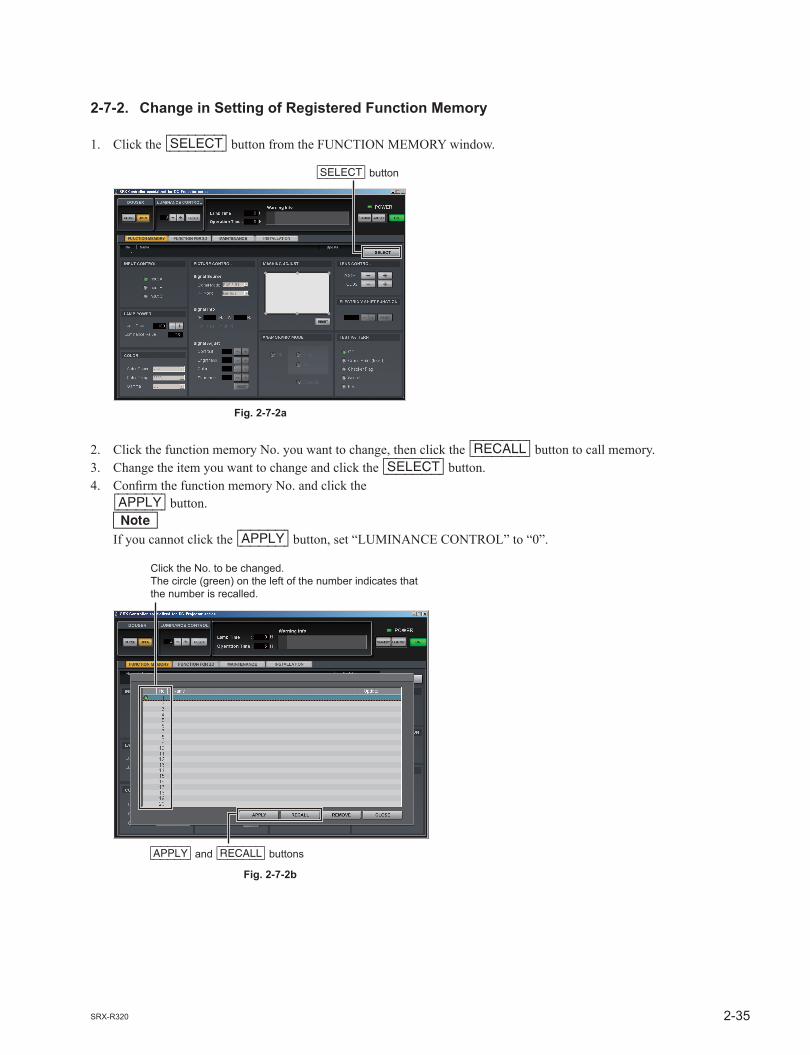
2-7-2. Change in Setting of Registered Function Memory
1. Click the [SELECT] button from the FUNCTION MEMORY window.
2. Click the function memory No. you want to change, then click the [RECALL] button to call memory.3. Change the item you want to change and click the [SELECT] button.4. Confi rm the function memory No. and click the
[APPLY] button. n If you cannot click the [APPLY] button, set “LUMINANCE CONTROL” to “0”.

2-36 SRX-R320
[SELECT] button
Fig. 2-7-3a
[APPLY] and [RECALL] buttons
Click the No. to be copied. The circle (green) on the left of the number indicates that the number is recalled.
Fig. 2-7-3b
2-7-3. Copying of Registered Function Memory to Create New Function Memory
1. Click the [SELECT] button from the FUNCTION MEMORY window.
2. Click the function memory No. you want to copy, then click the [RECALL] button to call memory.3. Change the item you want to change and click the [SELECT] button.4. Click the setting No. you want to register, enter a name, and click the [APPLY] button. n If you cannot click the [APPLY] button, set “LUMINANCE CONTROL” to “0”.

2-37SRX-R320
[SELECT] button
Fig. 2-7-4a
Click the No. to be registered.The circle (green) on the left of the number indicates that the number is recalled.
[RECALL] button [CLOSE] button
Fig. 2-7-4b
2-7-4. Switching of Registered Function Memory
1. Click the [SELECT] button from the FUNCTION MEMORY window.
2. Click the setting No. you want to switch.3. Click the [RECALL] button.4. Click the [CLOSE] button.

2-38 SRX-R320
2-8. How to Use the SRX Controller
The adjustment items of an SRX Controller are described below.nRefer to the described sections for the items below on an SRX Controller.. Installation: Section 2-1-1.. Connection: Section 2-1-2.. Startup: Section 2-1-3.
2-8-1. Confi guration
The SRX Controller consists of the following.. FUNCTION MEMORY window (Refer to 2 in Section 2-8-3.). FUNCTION FOR 3D window (Refer to 3 in Section 2-8-3.). MAINTENANCE window (Refer to 4 in Section 2-8-3.). INSTALLATION window (Refer to 5 in Section 2-8-3.)
2-8-2. Function Memory
In the SRX Controller, a total of 20 setting values for both 2D and 3D can be registered.In an initial value, the setting value is automatically memorized to No. 1. To register the setting value in another No., click the No. to be registered and adjust and set it on each window. (Refer to Section 2-7.)Refer to steps 1 and 2 of Section 2-7-3 when calling the registered setting value.

2-39SRX-R320
Fig. 2-8-3a
2-8-3. Functions of Each Window
1. Common items
DOUSER LUMINANCE CONTROL Lamp Time/Operation Time/Warning Info STANDBY/LAMP OFF/(POWER) ON
DOUSERSets “CLOSE” and “OPEN” of DOUSER.
LUMINANCE CONTROLSets the luminance of a lamp in this unit. The luminance is set in units of 1% by lamp power.nIn a premium preview, this function controls brightness without using the setting of function memory. Function memory cannot be used when this function is used.
. [+] button: Luminance increases.
. [_] button: Luminance decreases.
Lamp Time/Operation Time/Warning Info. Lamp Time: Displays the operation time of a lamp.. Operation Time: Displays the operation time of this unit.. Warning Info: Displays the contents of warning.
STANDBY/LAMP OFF/(POWER) ON. STANDBY: Puts this unit into the standby state. (Canceled using an [ON] button.). LAMP OFF: Turns off a lamp. (Canceled using an [ON] button.). (POWER) ON: Turns on the power.

2-40 SRX-R320
Fig. 2-8-3b
2. FUNCTION MEMORY window
INPUT CONTROL LAMP POWER COLOR PICTURE CONTROL MASKING ADJUST ANAMORPHIC MODE LENS CONTROL ELECTRIC V SHIFT FUNCTION TEST PATTERN
INPUT CONTROLSelects from which equipment the data is input.. Input A: Input from the DVI board (default) or optional board. Input B: Input from the optional board. Input C: Input from LMT-300
LAMP POWERCan adjust the output of a light source lamp in units of 1% between 50% and 100%. The screen becomes dark when a numeric value decreases. In this case, however, the power consumption decreases and the life of a lamp becomes long.. [+] button: The numeric value increases.. [_] button: The numeric value decreases.
nWhen the 4.2 kW lamp bulb is used, it can be adjusted between 53% and 100%.

2-41SRX-R320
COLORSets so that color reproduction can be obtained correctly.Confi rm the color from the setting of Color Space when there is abnormality in the color of an image.. Color Space: Adjusts the reproduction range of color tune. - 709: Select when projecting an ordinary Hi-Vision signal or RGB signal. - DCDM: Used when projecting using Minimum D-Cinema Color Gamut prescribed in a DCI
specifi cation book/version 1.0. - CIE XYZ: Used when projecting a special material having a wide chromaticity band exceeding
DCDM. - CUSTOM1: The initial value of DCDM is set. - Virtual White: Select when displaying the signal created by D65 or D55 WP on the display adjust-
ment DCI SPEC.. Color Temp: Select the color temperature. - DCI W/P: Select when projecting a movie material. - 6500: It is recommended to use this setting when projecting an ordinary Hi-Vision signal
or RGB signal. - CUSTOM1 to 4: The initial value of DCI W/P is set.. Gamma: Select a gamma correction mode. (Select from 2.6, 2.2, or 1.8.) The screen becomes bright as a numeric value decreases. Select the gamma correc-
tion mode according to the video source. It is recommended to use 2.2 when pro-jecting an ordinary Hi-Vision signal or RGB signal.
PICTURE CONTROLPerforms the selection of an input signal or the adjustment of picture quality.. Signal Source - Signal Mode: Select the input signal from the equipment selected using INPUT
CONTROL. n If the setting of Signal Mode does not correspond to the input signal,
the tone is not correctly displayed and the black is displayed grayly. - I/P Mode: Select an I/P conversion mode. Select Interlace, PsF, and 1080
50p/60p according to the input signal.. Signal Info (Signal information): Displays the horizontal/vertical frequency of an input signal auto-
matically. (The numeric value is displayed as a rough standard.) The type of an input signal is displayed below the frequency display.
- fH: Displays a horizontal frequency. - fV: Displays a vertical frequency.. Signal Adjust: Adjusts the picture quality of an input signal. A setting value increases when you click the [+] button. A numeric
value decreases when you click the [_] button. The adjustable items in a Signal Adjust menu are returned to the factory setting when you click the [RESET] button.
- Contrast: Adjusts the contrast. The contrast becomes strong as a setting value increases.
- Brightness: Adjusts the brightness. The brightness becomes strong as a setting value increases.
- Color: Adjusts the depth of color. The color becomes dark as a setting value increases.
- Sharpness: Adjusts the sharpness. An image becomes sharp as a setting value increases. It becomes soft as a setting value decreases.

2-42 SRX-R320
Adjusting points
Adjusting points
Fig. 2-8-3c
Fig. 2-8-3d
MASKING ADJUSTAdjusts the image masking according to the screen shape by the six adjusting point respectively. And adjustment value is displayed by pointing the cursor at each adjusting point.
When an adjusting point is double-clicked, the adjustment window is displayed.
A setting value increases when you click the [+] button. A numeric value decreases when you click the [_] button. The numeric value can also be entered directly.Each setting value is as follows: to : 0 to 950, : _500 to 500nAfter the adjusting of adjusting point to is completed, perform the adjusting of adjusting point and .
All items in a MASKING ADJUST menu are returned to the factory setting when you click the [RESET] button.

2-43SRX-R320
1314
pix
el
1714
pix
el
2160
pix
el
4096 pixel
3696 pixel
1760
pix
el
2160
pix
el
4096 pixel
3996 pixel
3596 pixel
Fig. 2-8-3e
ANAMORPHIC MODESets the mode when the anamorphic lens is attached. And sets the squeeze ON/OFF when the standard lens is installed.nWhen Scope or Flat is set, a signal convert to the anamorphic lens size data (1280 x 720 or 1920 x 1080), even if the signal input from INPUT A / B is not DCP.. Off: Normal image size. Scope: When the anamorphic lens is attached, this is selected in the case of the DCP for Scope size. . Flat: When the anamorphic lens is attached, this is selected in the case of the DCP for Flat size.. Squeeze: When the normal lens is attached, this is selected when you want to set Squeeze for aspect.
LENS CONTROLAdjusts the image projected on the screen.. ZOOM: Adjusts the size of an image. An image is expanded when you click the [+] button. It is
reduced when you click the [_] button.. FOCUS: Adjusts a focus. A focus is adjusted to the distance place when you click the [+] button. It is
adjusted to the nearby place when you click the [_] button.
ELECTRIC V SHIFT FUNCTIONAdjusts the vertical position of the projection screen electrically. The screen moves upwards when a setting value increases. It moves downwards when a setting value decreases. The setting value is re-turned to the factory setting when you click the [RESET] button.
TEST PATTERNAn image can be adjusted by projecting the test pattern, built in this unit, on the screen without inputting the signal from other equipment.Each test pattern is as follows:. Cross Hatch (Invert). Checker Flag. Scope. FlatSelect Off when not projecting a test pattern on the screen.
nThe test patterns Scope and Flat are as shown in the fi gure below.When installing, those patterns are used in fi tting the image size or masking the projection data.
Scope Flat

2-44 SRX-R320
Fig. 2-8-3f
3. FUNCTION FOR 3D window
This function is used for adjustment of 3D lens.For this function, refer to the “INSTALLATION AND SERVICE MANUAL” of LKRL-A002/A003.

2-45SRX-R320
Fig. 2-8-3g
Fig. 2-8-3h
4. MAINTENANCE window
WHITE BALANCE REGISTRATION ADJUST VERSION INFORMATION LAMP TIMER RESET LUMINANCE ADJUST AIR FILTER TIMER MAINTENANCE TIMER COLOR SPACE CONVERTER (Refer to Section 2-5.) GHOST BUSTERS TEST PATTERN
WHITE BALANCEChanges the Custom1 to Custom4 values of “Color Temp” in the “COLOR” menu on the FUNCTION MEMORY window.m. This menu is displayed only when Custom1 to Custom4 of “Color Temp” is selected.
. The value changed here is refl ected on only “Color Temp”.

2-46 SRX-R320
REGISTRATION ADJUSTMoves R (red), G (green), and B (blue) in the horizontal and vertical directions by two pixels (maximum) one pixel at a time so as to adjust registration.. H: Pixels move in the horizontal direction. R: Red pixels horizontally move by two pixels (maximum) one pixel at a time when you click the
[+]/[_] button. G: Green pixels horizontally move by two pixels (maximum) one pixel at a time when you click the
[+]/[_] button. B: Blue pixels horizontally move by two pixels (maximum) one pixel at a time when you click the
[+]/[_] button.. V: Pixels moves in the vertical direction. R: Red pixels vertically moves by two pixels (maximum) one pixel at a time when you click the
[+]/[_] button. G: Green pixels vertically moves by two pixels (maximum) one pixel at a time when you click the
[+]/[_] button. B: Blue pixels vertically moves by two pixels (maximum) one pixel at a time when you click the
[+]/[_] button.
VERSION INFORMATIONDisplays the version of this unit.Click the [VERSION] button.
LAMP TIMERResets the operation time of a used lamp before replacement.Click the [RESET] button and enter a serial number in the “LAMP INFORMATION” menu.
LUMINANCE ADJUSTKeeps the brightness of a lamp constant. Click the [CALIBRATE] button when a lamp became dark. The brightness of a lamp is adjusted automatically.nIt is operative when “Luminance” is selected in the Lamp Control Mode menu on the INSTALLATION window.
Fig. 2-8-3i[VERSION] button

2-47SRX-R320
1314
pix
el
1714
pix
el
2160
pix
el
4096 pixel
3696 pixel
1760
pix
el
2160
pix
el
4096 pixel
3996 pixel
3596 pixel
Fig. 2-8-3j
AIR FILTER TIMERResets the operation time of a used fi lter before replacement.After the fi lter is replaced, click the [RESET] button.. Optical. P/S ConverternNo P/S converter fi lter is used for this unit.
MAINTENANCE TIMER. Elapsed TimerDisplays the cumulative operation time of lamp.Click the [CLOSE] button to exit the “MAINTENANCE TIMER” menu.
GHOST BUSTERSThis function is used for adjustment of an 3D lens.For this function, refer to the “INSTALLATION AND SERVICE MANUAL” of LKRL-A002/A003.
TEST PATTERNAn image can be adjusted by projecting the test pattern, built in this unit, on the screen without inputting the signal from other equipment.Each test pattern is as follows:. Cross Hatch. Cross Hatch (Invert). Checker Flag. Scope. Flat. Test Mode 1Select Off when not projecting a test pattern on the screen.
m. A “COLOR SPACE CONVERTER” menu cannot be operated while a test pattern is displayed.. For TEST PATTERN of signal 3D, refer to the “INSTALLATION AND SERVICE MANUAL” of
LKRL-A002/A003.. The test patterns Scope and Flat are as shown in the fi gure below. When installing, those patterns are used in fi tting the image size or masking the projection data.
Scope Flat

2-48 SRX-R320
Fig. 2-8-3k
5. INSTALLATION window
Login Account Internet Setting Time Setting Lamp Control Mode
Login AccountA login account can be added.
Internet SettingSet when connecting this unit and PC through Ethernet during use of an SRX Controller. After setting, click the [APPLY] button.During initial setting, this item is set to RS-232C connection.
Time SettingSets the installation place of this unit and the current time.After setting, click the [APPLY] button.. Time Zone: Sets the area in which this unit is installed. Click the check box for “Adjust clock for daylight saving changes” when
setting summer time.. Date & Time: - Date: Sets the date. - Time: Sets the time.. Time Server (NTP Server): Enter the address of a network time server in the “Address” column.
Lamp Control ModeSelects the Lamp Control Mode.. Lamp Power The lamp wattage is stored in the Function memory.. Luminance The internal sensor luminance value is stored in the Function memory.
n When Luminance is selected, perform calibration periodically in order to maintain the stored luminance at a constant level correcting the deterioration of lamp luminance. (Refer to Section 2-2.)

3-1SRX-R320
Section 3Error Message
The following messages are displayed in the status message display at the back of the main unit and the “Warning Info” of an SRX controller.These messages are classifi ed into ALERT (degree of risk: high), WARNING (degree of risk: middle), and FAILURE (degree of risk: low) according to the degree of risk.Take proper measures according to the message number and the remedy.nFor WARNING (degree of risk: middle) and FAILURE (degree of risk: low), the power is not automati-cally turned off during operation of the main unit (during projection). However, take proper measures according to the remedy when the power is turned off next.

3-2 SRX-R320
ALERT (Degree of risk: high)
Message No. Error message Trouble Remedy
ALERT_01 BOARD ERROR The power of IFA board is defective. Check the IFA board. Replace the IFA board if it is damaged.
ALERT_02 BOARD ERROR The power of IFB board is defective. Check the IFB board. Replace the IFB board if it is damaged.
ALERT_03 BOARD ERROR The power of IFC board is defective. Check the IFC board. Replace the IFC board if it is damaged.
ALERT_04 BOARD ERROR The power of IFD board is defective. Check the IFD board. Replace the IFD board if it is damaged.
ALERT_05 BOARD ERROR The power of the MX board is defective. Check the MX board. Replace the MX board if it is damaged.
ALERT_06 BOARD ERROR The power of the LPD board is defective. Check the LPD board. Replace the LPD board if it is damaged.
ALERT_07 BOARD ERROR The power of the CT board is defective. Check the CT board. Replace the CT board if it is damaged.
ALERT_08 BOARD ERROR The power of the DST board is defective. Check the DST board. Replace the DST board if it is damaged.
ALERT_09 BOARD ERROR The power of the PR1 board is defective. Check the PR1 board. Replace the PR1 board if it is damaged.
ALERT_10 BOARD ERROR The power of the PR2 board is defective. Check the PR2 board. Replace the PR2 board if it is damaged.
ALERT_11 BOARD ERROR The power of the SY board is defective. Check the SY board. Replace the SY board if it is damaged.
ALERT_12 BOARD DETACHED The CN board is disconnected. Check the CN board.
ALERT_13 BOARD DETACHED The MX board is disconnected. Check the MX board.
ALERT_14 BOARD DETACHED The LPD board is disconnected. Check the LPD board.
ALERT_15 BOARD DETACHED The CT board is disconnected. Check the CT board.
ALERT_16 BOARD DETACHED The DST board is disconnected. Check the DST board.
ALERT_17 BOARD DETACHED The PR1 board is disconnected. Check the PR1 board.
ALERT_18 BOARD DETACHED The PR2 board is disconnected. Check the PR2 board.
ALERT_19 TEMPERATURE ERROR The unit stops operation by temperature abnormality of the R panel.
Check the outside air temperature, and air supply and exhaust. Check the Peltier R. Replace the Peltier R if it is damaged.
ALERT_20 TEMPERATURE ERROR The unit stops operation by temperature abnormality of the G panel.
Check the outside air temperature, and air supply and exhaust. Check the Peltier G. Replace the Peltier G if it is damaged.
ALERT_21 TEMPERATURE ERROR The unit stops operation by temperature abnormality of the B panel.
Check the outside air temperature, and air supply and exhaust. Check the Peltier B. Replace the Peltier B if it is damaged.
ALERT_22 COVER DETACHED The rear cabinet is detached and/or the cold mirror is out of position.
Check the panel (U4) block assembly and cold mirror position.
ALERT_27 FAN ERROR The lamp fan A is defective. Check the lamp fan A. Replace the fan if it is damaged.
ALERT_28 FAN ERROR The lamp fan B is defective. Check the lamp fan B. Replace the fan if it is damaged.
ALERT_29 FAN ERROR The lamp fan C is defective. Check the lamp fan C. Replace the fan if it is damaged.
ALERT_30 FAN ERROR The lamp fan D is defective. Check the lamp fan D. Replace the fan if it is damaged.
ALERT_32 BALLAST ERROR The unit stops operation by temperature abnormality of the power unit for lamp.
Check the outside air temperature, air supply and exhaust, and power unit for lamp. Replace the power unit for lamp if it is damaged.
(Continued)

3-3SRX-R320
Message No. Error message Trouble Remedy
ALERT_33 BALLAST ERROR The power unit for lamp fan is abnormal. Check the power unit for lamp fan. Re-place the fan if it is damaged.
ALERT_34 BALLAST ERROR The power unit for lamp is abnormal. Check the cable between the power unit for lamp and lamp house. Check the power unit for lamp. Replace the power unit for lamp if it is damaged.
ALERT_35 LAMP ERROR The lamp goes off. Check the lamp. Replace lamp bulb if it is damaged. Check the power unit for lamp. Replace the power unit for lamp if it is damaged.
ALERT_36 BALLAST ERROR The power unit for lamp is abnormal. Check the cable between the power unit for lamp and lamp house. Check the power unit for lamp. Replace the power unit for lamp if it is damaged.
ALERT_37 COVER DETACHED The maintenance cover assembly is out of position.
Check the maintenance cover assembly.
ALERT_38 BOARD ERROR The power of the CN board is defective. Check the CN board. Replace the board if it is damaged.
ALERT_39 TEMPERATURE ERROR The unit stops operation by temperature abnormality of the 8-inch duct block.
Check the outside air temperature, the suction amount of a 8-inch duct, and the lamp fans A to D.
ALERT_41 COVER DETACHED The unit stops operation by the fi lter cover detaching.
Check that the fi lter cover (door) is not open.
WARNING (Degree of risk: middle)
Message No. Error message Trouble Remedy
WARN_01 FAN ERROR The power fan 1 is abnormal. Check the power fan 1. Replace the power fan 1 if it is damaged.
WARN_02 FAN ERROR The power fan 2 is abnormal. Check the power fan 2. Replace the power fan 2 if it is damaged.
WARN_05 FAN ERROR The board fan 1 is abnormal. Check the board fan 1. Replace the board fan 1 if it is damaged.
WARN_06 FAN ERROR The board fan 2 is abnormal. Check the board fan 2. Replace the board fan 2 if it is damaged.
WARN_12 FAN ERROR The Peltier R fan is abnormal. Check the Peltier R fan. Replace the Peltier R fan if it is damaged.
WARN_13 FAN ERROR The Peltier G fan is abnormal. Check the Peltier G fan. Replace the Peltier G fan if it is damaged.
WARN_14 FAN ERROR The Peltier B fan is abnormal. Check the Peltier B fan. Replace the Peltier B fan if it is damaged.
WARN_20 DEVICE ERROR The Peltier R is out of control. Check the outside air temperature, and air supply and exhaust. Check the Peltier R. Replace the Peltier R if it is damaged.
WARN_21 DEVICE ERROR The Peltier G is out of control. Check the outside air temperature, and air supply and exhaust. Check the Peltier G. Replace the Peltier G if it is damaged.
WARN_22 DEVICE ERROR The Peltier B is out of control. Check the outside air temperature, and air supply and exhaust. Check the Peltier B. Replace the Peltier B if it is damaged.
WARN_23 CONNECTOR DE-TACHED
The connector of a Peltier R is discon-nected.
Check the connector of a Peltier R.
WARN_24 CONNECTOR DE-TACHED
The connector of a Peltier G is discon-nected.
Check the connector of a Peltier G.
WARN_25 CONNECTOR DE-TACHED
The connector of a Peltier B is discon-nected.
Check the connector of a Peltier B.
(Continued)

3-4 SRX-R320
Message No. Error message Trouble Remedy
WARN_26 DOUSER ERROR DOUSER operation is failed. Check the connector of a shift block. Check the shift block. Replace the shift block if it is damaged.
WARN_27 BALLAST ERROR A power unit for lamp communication failed.
Check the cable between the power unit for lamp and lamp house. Check the power unit for lamp. Replace the power unit for lamp if it is damaged.
WARN_28 BALLAST ERROR Lamp serial number setting is wrong. Check the range setting of power unit for lamp and the serial information of a lamp.
WARN_29 EXHAUST ERROR The air volume of the 8-inch duct is abnormal.
Check the air volume at the outlet of the 8-inch duct.*1
WARN_30 COVER DETACHED The fi lter cover is detached. Check that the fi lter cover (door) is not opened.
WARN_31 FAN ERROR PS converter fan 2 in abnormal. Check the PS converter fan 2. Replace the PS converter fan 2 if it is damaged.
WARN_32 FAN ERROR PS converter fan 1 in abnormal. Check the PS converter fan 1. Replace the PS converter fan 1 if it is damaged.
WARN_33 FAN ERROR PBS fan in abnormal. Check the PBS fan. Replace the PBS fan if it is damaged.
*1: Warning is displayed when the air volume at the outlet of the 8-inch duct is under 250 ft3/min (7 m3/min). The exhaust air volume required is 450 to 550 ft3/min (12.7 to 15.6 m3/min).
FAILURE (Degree of risk: low)
Message No. Error message Trouble Remedy
FAIL_02 TEMPERATURE ERROR Warning for temperature abnormality of the 8-inch duct.
Check the outside air temperature, the suction amount of a 8-inch duct, and the lamp cooling fans.
FAIL_04 TEMPERATURE ERROR Intake temperature is abnormal. Check the outside air temperature.
FAIL_06 TEMPERATURE ERROR The optical unit block temperature is abnormal.
Check the outside air temperature, and air supply and exhaust.
FAIL_10 TEMPERATURE ERROR Warning for temperature abnormality of the R panel.
Check the outside air temperature, and air supply and exhaust. Check the Peltier R. Replace the Peltier R if it is damaged.
FAIL_11 TEMPERATURE ERROR Warning for temperature abnormality of the G panel.
Check the outside air temperature, and air supply and exhaust. Check the Peltier G. Replace the Peltier G if it is damaged.
FAIL_12 TEMPERATURE ERROR Warning for temperature abnormality of the B panel.
Check the outside air temperature, and air supply and exhaust. Check the Peltier B. Replace the Peltier B if it is damaged.
FAIL_15 TEMPERATURE ERROR Warning for temperature abnormality of the power unit for lamp.
Check the outside air temperature. Check the power unit for lamp. Replace the power unit for lamp if it is damaged.
FAIL_16 LENS ERROR Zoom does not reach the registered position.
Check the function operation, lens, and lens cable. Check the SY board. Replace the SY board if it is damaged.
FAIL_17 LENS ERROR Focus does not reach the registered position.
Check the function operation, lens, and lens cable. Check the SY board. Replace the SY board if it is damaged.
FAIL_18 LENS ERROR Zoom operation is failed. Check the lens and lens cable. Check the SY board. Replace the SY board if it is damaged.
(Continued)

3-5SRX-R320
Message No. Error message Trouble Remedy
FAIL_19 LENS ERROR Focus operation is failed. Check the lens and lens cable. Check the SY board. Replace the SY board if it is damaged.
FAIL_21 ADJUSTMENT ERROR The Z-axis operation is failed. Check the lamp house-supplied motor and harness. Replace the motor if it is dam-aged. Check the SY board. Replace the SY board if it is damaged.
FAIL_24 ADJUSTMENT ERROR Calibration is failed. Perform recalibration, check the lamp (luminance deterioration). Replace the lamp bulb if it is deteriorated.
FAIL_25 DEVICE ERROR FPGA confi guration fails. Turn off the power once, then turn on it again.
FAIL_26 DEVICE ERROR I2C communication error. Turn off the power once, then turn on it again.
FAIL_27 DEVICE ERROR LVDS error Turn off the power once, then turn on it again.
FAIL_28 DEVICE ERROR PLL error Turn off the power once, then turn on it again.
FAIL_29 DEVICE ERROR Parity error Turn off the power once, then turn on it again.
FAIL_30 BALLAST ERROR The power unit for lamp is interlocked. Turn off the power once, then turn on it again.
FAIL_34 ADJUSTMENT ERROR The Z-axis is gotten out of range in the + direction.
Readjust the Z-axis and save it. Return the Z-axis in the _ direction.(Refer to Section 2-2.)
FAIL_35 ADJUSTMENT ERROR The Z-axis is gotten out of range in the _ direction.
Readjust the Z-axis and save it. Return the Z-axis in the + direction.(Refer to Section 2-2.)
FAIL_36 DEVICE ERROR Setting error of DVI. Check the setting and set the operation again.

3-6 SRX-R320
nFan location
Top view
7 Front side
Lamp fan ALamp fan B
Lamp fan CLamp fan D
Peltier R fan
Peltier G fan
Peltier B fan
DSTboard
Filter cover
PBS fan
PS converter fan 1
CN board
PS converter fan 2
Front side
3-7SRX-R320
Notice Concerning Software Governed by the GNU GPL/LGPLThis product includes software to which the GNU General Public License (“GPL”) or GNU Lesser Gen-eral Public License (“LGPL”) applies. Under the terms of the GPL/LGPL, of which a copy is attached, you have the right to obtain, modify, and distribute copies of the source code of this software.
Package listgcc-4.1glibc-2.3.6binutils-2.17hermit-pj-1.0.0.0linux-2.6.12.5-pj3sony-dist-20090311
To Obtain information on the source code and/or the source code for this software. Consult your nearest Sony Service.
GNU GENERAL PUBLIC LICENSEVersion 2, June 1991
Copyright (C) 1989, 1991 Free Software Foundation, Inc.59 Temple Place, Suite 330, Boston, MA 02111-1307 USAEveryone is permitted to copy and distribute verbatim copies of this license document, but changing it is not allowed.
PreambleThe licenses for most software are designed to take away your freedom to share and change it. By con-trast, the GNU General Public License is intended to guarantee your freedom to share and change free software--to make sure the software is free for all its users. This General Public License applies to most of the Free Software Foundation’s software and to any other program whose authors commit to using it. (Some other Free Software Foundation software is covered by the GNU Library General Public License instead.) You can apply it to your programs, too.
When we speak of free software, we are referring to freedom, not price. Our General Public Licenses are designed to make sure that you have the freedom to distribute copies of free software (and charge for this service if you wish), that you receive source code or can get it if you want it, that you can change the software or use pieces of it in new free programs; and that you know you can do these things.
To protect your rights, we need to make restrictions that forbid anyone to deny you these rights or to ask you to surrender the rights.These restrictions translate to certain responsibilities for you if you distribute copies of the software, or if you modify it.
For example, if you distribute copies of such a program, whether gratis or for a fee, you must give the recipients all the rights that you have. You must make sure that they, too, receive or can get the source code. And you must show them these terms so they know their rights.
We protect your rights with two steps: (1) copyright the software, and (2) offer you this license which gives you legal permission to copy, distribute and/or modify the software.

3-8 SRX-R320
Also, for each author’s protection and ours, we want to make certain that everyone understands that there is no warranty for this free software. If the software is modifi ed by someone else and passed on, we want its recipients to know that what they have is not the original, so that any problems introduced by others will not refl ect on the original authors’ reputations.
Finally, any free program is threatened constantly by software patents. We wish to avoid the danger that redistributors of a free program will individually obtain patent licenses, in effect making the program propri-etary. To prevent this, we have made it clear that any patent must be licensed for everyone’s free use or not licensed at all.
The precise terms and conditions for copying, distribution and modifi cation follow.
GNU GENERAL PUBLIC LICENSETERMS AND CONDITIONS FOR COPYING, DISTRIBUTION AND MODIFICATION
0. This License applies to any program or other work which contains a notice placed by the copyright holder saying it may be distributed under the terms of this General Public License. The “Program”, below, refers to any such program or work, and a “work based on the Program” means either the Program or any derivative work under copyright law: that is to say, a work containing the Program or a portion of it, either verbatim or with modifi cations and/or translated into another language. (Hereinafter, translation is included without limitation in the term “modifi cation”.) Each licensee is addressed as “you”.
Activities other than copying, distribution and modifi cation are not covered by this License; they are outside its scope. The act of running the Program is not restricted, and the output from the Program is covered only if its contents constitute a work based on the Program (independent of having been made by running the Program).
Whether that is true depends on what the Program does.
1. You may copy and distribute verbatim copies of the Program’s source code as you receive it, in any medium, provided that you conspicuously and appropriately publish on each copy an appropriate copyright notice and disclaimer of warranty; keep intact all the notices that refer to this License and to the absence of any warranty; and give any other recipients of the Program a copy of this License along with the Program.
You may charge a fee for the physical act of transferring a copy, and you may at your option offer warranty protection in exchange for a fee.
2. You may modify your copy or copies of the Program or any portion of it, thus forming a work based on the Program, and copy and distribute such modifi cations or work under the terms of Section 1 above, provided that you also meet all of these conditions:
a) You must cause the modifi ed fi les to carry prominent notices stating that you changed the fi les and the date of any change.
b) You must cause any work that you distribute or publish, that in whole or in part contains or is derived from the Program or any part thereof, to be licensed as a whole at no charge to all third parties under the terms of this License.

3-9SRX-R320
c) If the modifi ed program normally reads commands interactively when run, you must cause it, when started running for such interactive use in the most ordinary way, to print or display an an-nouncement including an appropriate copyright notice and a notice that there is no warranty (or else, saying that you provide a warranty) and that users may redistribute the program under these condi-tions, and telling the user how to view a copy of this License. (Exception: if the Program itself is inter-active but does not normally print such an announcement, your work based on the Program is not required to print an announcement.)
These requirements apply to the modifi ed work as a whole. If identifi able sections of that work are not derived from the Program, and can be reasonably considered independent and separate works in themselves, then this License, and its terms, do not apply to those sections when you distribute them as separate works. But when you distribute the same sections as part of a whole which is a work based on the Program, the distribution of the whole must be on the terms of this License, whose permissions for other licensees extend to the entire whole, and thus to each and every part regardless of who wrote it.
Thus, it is not the intent of this section to claim rights or contest your rights to work written entirely by you; rather, the intent is to exercise the right to control the distribution of derivative or collective works based on the Program.
In addition, mere aggregation of another work not based on the Program with the Program (or with a work based on the Program) on a volume of a storage or distribution medium does not bring the other work under the scope of this License.
3. You may copy and distribute the Program (or a work based on it, under Section 2) in object code or executable form under the terms of Sections 1 and 2 above provided that you also do one of the following:
a) Accompany it with the complete corresponding machine-readablesource code, which must be distributed under the terms of Sections 1 and 2 above on a medium customarily used for software interchange; or,
b) Accompany it with a written offer, valid for at least three years, to give any third party, for a charge no more than your cost of physically performing source distribution, a complete machine-read-able copy of the corresponding source code, to be distributed under the terms of Sections 1 and 2 above on a medium customarily used for software interchange; or,
c) Accompany it with the information you received as to the offer to distribute corresponding source code. (This alternative is allowed only for noncommercial distribution and only if you received the program in object code or executable form with such an offer, in accord with Subsection b above.)
The source code for a work means the preferred form of the work for making modifi cations to it. For an executable work, complete source code means all the source code for all modules it contains, plus any associated interface defi nition fi les, plus the scripts used to control compilation and installation of the executable. However, as a special exception, the source code distributed need not include anything that is normally distributed (in either source or binary form) with the major components (compiler, kernel, and so on) of the operating system on which the executable runs, unless that component itself accompanies the executable.

3-10 SRX-R320
If distribution of executable or object code is made by offering access to copy from a designated place, then offering equivalent access to copy the source code from the same place counts as distribution of the source code, even though third parties are not compelled to copy the source along with the object code.
4. You may not copy, modify, sublicense, or distribute the Program except as expressly provided under this License. Any attempt otherwise to copy, modify, sublicense or distribute the Program is void, and will automatically terminate your rights under this License.
However, parties who have received copies, or rights, from you under this License will not have their licenses terminated so long as such parties remain in full compliance.
5. You are not required to accept this License, since you have not signed it. However, nothing else grants you permission to modify or distribute the Program or its derivative works. These actions are prohibited by law if you do not accept this License. Therefore, by modifying or distributing the Program (or any work based on the Program), you indicate your acceptance of this License to do so, and all its terms and conditions for copying, distributing or modifying the Program or works based on it.
6. Each time you redistribute the Program (or any work based on the Program), the recipient automati-cally receives a license from the original licensor to copy, distribute or modify the Program subject to these terms and conditions. You may not impose any further restrictions on the recipients’ exercise of the rights granted herein.
You are not responsible for enforcing compliance by third parties to this License.
7. If, as a consequence of a court judgment or allegation of patent infringement or for any other reason (not limited to patent issues), conditions are imposed on you (whether by court order, agreement or other-wise) that contradict the conditions of this License, they do not excuse you from the conditions of this License. If you cannot distribute so as to satisfy simultaneously your obligations under this License and any other pertinent obligations, then as a consequence you may not distribute the Program at all. For example, if a patent license would not permit royalty-free redistribution of the Program by all those who receive copies directly or indirectly through you, then the only way you could satisfy both it and this License would be to refrain entirely from distribution of the Program.
If any portion of this section is held invalid or unenforceable under any particular circumstance, the bal-ance of the section is intended to apply and the section as a whole is intended to apply in other cir-cumstances.
It is not the purpose of this section to induce you to infringe any patents or other property right claims or to contest validity of any such claims; this section has the sole purpose of protecting the integrity of the free software distribution system, which is implemented by public license practices. Many people have made generous contributions to the wide range of software distributed through that system in reli-ance on consistent application of that system; it is up to the author/donor to decide if he or she is willing to distribute software through any other system and a licensee cannot impose that choice.
This section is intended to make thoroughly clear what is believed to be a consequence of the rest of this License.

3-11SRX-R320
8. If the distribution and/or use of the Program is restricted in certain countries either by patents or by copyrighted interfaces, the original copyright holder who places the Program under this License may add an explicit geographical distribution limitation excluding those countries, so that distribution is permitted only in or among countries not thus excluded. In such case, this License incorporates the limitation as if written in the body of this License.
9. The Free Software Foundation may publish revised and/or new versions of the General Public License from time to time. Such new versions will be similar in spirit to the present version, but may differ in detail to address new problems or concerns.
Each version is given a distinguishing version number. If the Program specifi es a version number of this License which applies to it and “any later version”, you have the option of following the terms and conditions either of that version or of any later version published by the Free Software Foundation. If the Program does not specify a version number of this License, you may choose any version ever pub-lished by the Free Software Foundation.
10. If you wish to incorporate parts of the Program into other free programs whose distribution conditions are different, write to the author to ask for permission. For software which is copyrighted by the Free Software Foundation, write to the Free Software Foundation; we sometimes make exceptions for this. Our decision will be guided by the two goals of preserving the free status of all derivatives of our free software and of promoting the sharing and reuse of software generally.
NO WARRANTY11. BECAUSE THE PROGRAM IS LICENSED FREE OF CHARGE, THERE IS NO WARRANTY FOR
THE PROGRAM, TO THE EXTENT PERMITTED BY APPLICABLE LAW. EXCEPT WHEN OTHER-WISE STATED IN WRITING THE COPYRIGHT HOLDERS AND/OR OTHER PARTIES PROVIDE THE PROGRAM “AS IS” WITHOUT WARRANTY OF ANY KIND, EITHER EXPRESSED OR IMPLIED, INCLUDING, BUT NOT LIMITED TO, THE IMPLIED WARRANTIES OF MERCHANTABILITY AND FITNESS FOR A PARTICULAR PURPOSE. THE ENTIRE RISK AS TO THE QUALITY AND PERFOR-MANCE OF THE PROGRAM IS WITH YOU. SHOULD THE PROGRAM PROVE DEFECTIVE, YOU ASSUME THE COST OF ALL NECESSARY SERVICING,REPAIR OR CORRECTION.
12. IN NO EVENT UNLESS REQUIRED BY APPLICABLE LAW OR AGREED TO IN WRITING WILL ANY COPYRIGHT HOLDER, OR ANY OTHER PARTY WHO MAY MODIFY AND/OR REDISTRIBUTE THE PROGRAM AS PERMITTED ABOVE, BE LIABLE TO YOU FOR DAMAGES, INCLUDING ANY GEN-ERAL, SPECIAL, INCIDENTAL OR CONSEQUENTIAL DAMAGES ARISING OUT OF THE USE OR INABILITY TO USE THE PROGRAM (INCLUDING BUT NOT LIMITED TO LOSS OF DATA OR DATA BEING RENDERED INACCURATE OR LOSSES SUSTAINED BY YOU OR THIRD PARTIES OR A FAILURE OF THE PROGRAM TO OPERATE WITH ANY OTHER PROGRAMS), EVEN IF SUCH HOLDER OR OTHER PARTY HAS BEEN ADVISED OF THE POSSIBILITY OF SUCH DAMAGES.

3-12 SRX-R320
END OF TERMS AND CONDITIONSHow to Apply These Terms to Your New Programs
If you develop a new program, and you want it to be of the greatest possible use to the public, the best way to achieve this is to make it free software which everyone can redistribute and change under these terms.
To do so, attach the following notices to the program. It is safest to attach them to the start of each source fi le to most effectively convey the exclusion of warranty; and each fi le should have at least the “copyright” line and a pointer to where the full notice is found.
Copyright (C) This program is free software; you can redistribute it and/or modify it under the terms of the GNU General Public License as published by the Free Software Foundation; either version 2 of the License, or (at your option) any later version.
This program is distributed in the hope that it will be useful, but WITHOUT ANY WARRANTY; without even the implied warranty of MERCHANTABILITY or FITNESS FOR A PARTICULAR PURPOSE. See the GNU General Public License for more details.
You should have received a copy of the GNU General Public License along with this program; if not, write to the Free Software Foundation, Inc., 59 Temple Place, Suite 330, Boston, MA 02111-1307 USA
Also add information on how to contact you by electronic and paper mail.
If the program is interactive, make it output a short notice like this when it starts in an interactive mode:Gnomovision version 69, Copyright (C) year name of author Gnomovision comes with ABSOLUTELY NO WARRANTY; for details type `show w’. This is free software, and you are welcome to redistribute it under certain conditions; type `show c’ for details. The hypothetical commands `show w’ and `show c’ should show the appropriate parts of the General Public License. Of course, the commands you use may be called something other than `show w’ and `show c’; they could even be mouse-clicks or menu items--whatever suits your program.
You should also get your employer (if you work as a programmer) or your school, if any, to sign a “copyright disclaimer” for the program, if necessary. Here is a sample; alter the names:
Yoyodyne, Inc., hereby disclaims all copyright interest in the program `Gnomovision’ (which makes passes at compilers) written by James Hacker.
, 1 April 1989Ty Coon, President of Vice
This General Public License does not permit incorporating your program into proprietary programs. If your program is a subroutine library, you may consider it more useful to permit linking proprietary applications with the library. If this is what you want to do, use the GNU Library General Public License instead of this License.

3-13SRX-R320
GNU LESSER GENERAL PUBLIC LICENSEVersion 2.1, February 1999
Copyright (C) 1991, 1999 Free Software Foundation, Inc.59 Temple Place, Suite 330, Boston, MA 02111-1307 USAEveryone is permitted to copy and distribute verbatim copies of this license document, but changing it is not allowed.
[This is the fi rst released version of the Lesser GPL. It also counts as the successor of the GNU Library Public License, version 2, hence the version number 2.1.]
PreambleThe licenses for most software are designed to take away your freedom to share and change it. By con-trast, the GNU General Public Licenses are intended to guarantee your freedom to share and change free software--to make sure the software is free for all its users.
This license, the Lesser General Public License, applies to some specially designated software packages--typically libraries--of the Free Software Foundation and other authors who decide to use it. You can use it too, but we suggest you fi rst think carefully about whether this license or the ordinary General Public License is the better strategy to use in any particular case, based on the explanations below.
When we speak of free software, we are referring to freedom of use, not price. Our General Public Licens-es are designed to make sure that you have the freedom to distribute copies of free software (and charge for this service if you wish); that you receive source code or can get it if you want it; that you can change the software and use pieces of it in new free programs; and that you are informed that you can do these things.
To protect your rights, we need to make restrictions that forbid distributors to deny you these rights or to ask you to surrender these rights. These restrictions translate to certain responsibilities for you if you distribute copies of the library or if you modify it.
For example, if you distribute copies of the library, whether gratis or for a fee, you must give the recipients all the rights that we gave you. You must make sure that they, too, receive or can get the source code. If you link other code with the library, you must provide complete object fi les to the recipients, so that they can relink them with the library after making changes to the library and recompiling it. And you must show them these terms so they know their rights.
We protect your rights with a two-step method: (1) we copyright the library, and (2) we offer you this li-cense, which gives you legal permission to copy, distribute and/or modify the library.
To protect each distributor, we want to make it very clear that there is no warranty for the free library. Also, if the library is modifi ed by someone else and passed on, the recipients should know that what they have is not the original version, so that the original author’s reputation will not be affected by problems that might be introduced by others.
Finally, software patents pose a constant threat to the existence of any free program. We wish to make sure that a company cannot effectively restrict the users of a free program by obtaining a restrictive license from a patent holder. Therefore, we insist that any patent license obtained for a version of the library must be consistent with the full freedom of use specifi ed in this license.

3-14 SRX-R320
Most GNU software, including some libraries, is covered by the ordinary GNU General Public License. This license, the GNU Lesser General Public License, applies to certain designated libraries, and is quite different from the ordinary General Public License. We use this license for certain libraries in order to permit linking those libraries into non-free programs.
When a program is linked with a library, whether statically or using a shared library, the combination of the two is legally speaking a combined work, a derivative of the original library. The ordinary General Public License therefore permits such linking only if the entire combination fi ts its criteria of freedom. The Lesser General Public License permits more lax criteria for linking other code with the library.
We call this license the “Lesser” General Public License because it does Less to protect the user’s free-dom than the ordinary General Public License. It also provides other free software developers Less of an advantage over competing non-free programs. These disadvantages are the reason we use the ordinary General Public License for many libraries. However, the Lesser license provides advantages in certain special circumstances.
For example, on rare occasions, there may be a special need to encourage the widest possible use of a certain library, so that it becomes a de-facto standard. To achieve this, non-free programs must be allowed to use the library. A more frequent case is that a free library does the same job as widely used non-free libraries. In this case, there is little to gain by limiting the free library to free software only, so we use the Lesser General Public License.
In other cases, permission to use a particular library in non-free programs enables a greater number of people to use a large body of free software. For example, permission to use the GNU C Library in non-free programs enables many more people to use the whole GNU operating system, as well as its variant, the GNU/Linux operating system.
Although the Lesser General Public License is Less protective of the users’ freedom, it does ensure that the user of a program that is linked with the Library has the freedom and the wherewithal to run that pro-gram using a modifi ed version of the Library.
The precise terms and conditions for copying, distribution and modifi cation follow. Pay close attention to the difference between a “work based on the library” and a “work that uses the library”. The former contains code derived from the library, whereas the latter must be combined with the library in order to run.
GNU LESSER GENERAL PUBLIC LICENSETERMS AND CONDITIONS FOR COPYING, DISTRIBUTION AND MODIFICATION
0. This License Agreement applies to any software library or other program which contains a notice placed by the copyright holder or other authorized party saying it may be distributed under the terms of this Lesser General Public License (also called “this License”). Each licensee is addressed as “you”.
A “library” means a collection of software functions and/or data prepared so as to be conveniently linked with application programs (which use some of those functions and data) to form executables.
The “Library”, below, refers to any such software library or work which has been distributed under these terms. A “work based on the Library” means either the Library or any derivative work under copy-right law: that is to say, a work containing the Library or a portion of it, either verbatim or with modifi ca-tions and/or translated straightforwardly into another language. (Hereinafter, translation is included without limitation in the term “modifi cation”.)

3-15SRX-R320
“Source code” for a work means the preferred form of the work for making modifi cations to it. For a library, complete source code means all the source code for all modules it contains, plus any associ-ated interface defi nition fi les, plus the scripts used to control compilation and installation of the library.
Activities other than copying, distribution and modifi cation are not covered by this License; they are outside its scope. The act of running a program using the Library is not restricted, and output from such a program is covered only if its contents constitute a work based on the Library (independent of the use of the Library in a tool for writing it). Whether that is true depends on what the Library does and what the program that uses the Library does.
1. You may copy and distribute verbatim copies of the Library’s complete source code as you receive it, in any medium, provided that you conspicuously and appropriately publish on each copy an appropri-ate copyright notice and disclaimer of warranty; keep intact all the notices that refer to this License and to the absence of any warranty; and distribute a copy of this License along with the Library.
You may charge a fee for the physical act of transferring a copy, and you may at your option offer warranty protection in exchange for a fee.
2. You may modify your copy or copies of the Library or any portion of it, thus forming a work based on the Library, and copy and distribute such modifi cations or work under the terms of Section 1 above, provided that you also meet all of these conditions:
a) The modifi ed work must itself be a software library.
b) You must cause the fi les modifi ed to carry prominent notices stating that you changed the fi les and the date of any change.
c) You must cause the whole of the work to be licensed at no charge to all third parties under the terms of this License.
d) If a facility in the modifi ed Library refers to a function or a table of data to be supplied by an application program that uses the facility, other than as an argument passed when the facility is in-voked, then you must make a good faith effort to ensure that, in the event an application does not supply such function or table, the facility still operates, and performs whatever part of its purpose remains meaningful.
(For example, a function in a library to compute square roots has a purpose that is entirely well-defi ned independent of the application. Therefore, Subsection 2d requires that any application-supplied func-tion or table used by this function must be optional: if the application does not supply it, the square root function must still compute square roots.)
These requirements apply to the modifi ed work as a whole. If identifi able sections of that work are not derived from the Library, and can be reasonably considered independent and separate works in them-selves, then this License, and its terms, do not apply to those sections when you distribute them as separate works. But when you distribute the same sections as part of a whole which is a work based on the Library, the distribution of the whole must be on the terms of this License, whose permissions for other licensees extend to the entire whole, and thus to each and every part regardless of who wrote it.

3-16 SRX-R320
Thus, it is not the intent of this section to claim rights or contest your rights to work written entirely by you; rather, the intent is to exercise the right to control the distribution of derivative or collective works based on the Library.
In addition, mere aggregation of another work not based on the Library with the Library (or with a work based on the Library) on a volume of a storage or distribution medium does not bring the other work under the scope of this License.
3. You may opt to apply the terms of the ordinary GNU General Public License instead of this License to a given copy of the Library. To do this, you must alter all the notices that refer to this License, so that they refer to the ordinary GNU General Public License, version 2, instead of to this License. (If a newer version than version 2 of the ordinary GNU General Public License has appeared, then you can speci-fy that version instead if you wish.) Do not make any other change in these notices.
Once this change is made in a given copy, it is irreversible for that copy, so the ordinary GNU General Public License applies to all subsequent copies and derivative works made from that copy.
This option is useful when you wish to copy part of the code of the Library into a program that is not a library.
4. You may copy and distribute the Library (or a portion or derivative of it, under Section 2) in object code or executable form under the terms of Sections 1 and 2 above provided that you accompany it with the complete corresponding machine-readable source code, which must be distributed under the terms of Sections 1 and 2 above on a medium customarily used for software interchange.
If distribution of object code is made by offering access to copy from a designated place, then offering equivalent access to copy the source code from the same place satisfi es the requirement to distribute the source code, even though third parties are not compelled to copy the source along with the object code.
5. A program that contains no derivative of any portion of the Library, but is designed to work with the Library by being compiled or linked with it, is called a “work that uses the Library”. Such a work, in isolation, is not a derivative work of the Library, and therefore falls outside the scope of this License.
However, linking a “work that uses the Library” with the Library creates an executable that is a deriva-tive of the Library (because it contains portions of the Library), rather than a “work that uses the li-brary”. The executable is therefore covered by this License. Section 6 states terms for distribution of such executables.
When a “work that uses the Library” uses material from a header fi le that is part of the Library, the object code for the work may be a derivative work of the Library even though the source code is not. Whether this is true is especially signifi cant if the work can be linked without the Library, or if the work is itself a library. The threshold for this to be true is not precisely defi ned by law.
If such an object fi le uses only numerical parameters, data structure layouts and accessors, and small macros and small inline functions (ten lines or less in length), then the use of the object fi le is unre-stricted, regardless of whether it is legally a derivative work. (Executables containing this object code plus portions of the Library will still fall under Section 6.)

3-17SRX-R320
Otherwise, if the work is a derivative of the Library, you may distribute the object code for the work under the terms of Section 6. Any executables containing that work also fall under Section 6, whether or not they are linked directly with the Library itself.
6. As an exception to the Sections above, you may also combine or link a “work that uses the Li-brary” with the Library to produce a work containing portions of the Library, and distribute that work under terms of your choice, provided that the terms permit modifi cation of the work for the customer’s own use and reverse engineering for debugging such modifi cations.
You must give prominent notice with each copy of the work that the Library is used in it and that the Library and its use are covered by this License. You must supply a copy of this License. If the work during execution displays copyright notices, you must include the copyright notice for the Library among them, as well as a reference directing the user to the copy of this License. Also, you must do one of these things:
a) Accompany the work with the complete corresponding machine-readable source code for the Li-brary including whatever changes were used in the work (which must be distributed under Sections 1 and 2 above); and, if the work is an executable linked with the Library, with the complete machine-readable “work that uses the Library”, as object code and/or source code, so that the user can modify the Library and then relink to produce a modifi ed executable containing the modifi ed Library. (It is understood that the user who changes the contents of defi nitions fi les in the Library will not necessarily be able to recompile the application to use the modifi ed defi nitions.)
b) Use a suitable shared library mechanism for linking with the Library. A suitable mechanism is one that (1) uses at run time a copy of the library already present on the user’s computer system, rather than copying library functions into the executable, and (2) will operate properly with a modifi ed version of the library, if the user installs one, as long as the modifi ed version is interface-compatible with the version that the work was made with.
c) Accompany the work with a written offer, valid for at least three years, to give the same user the materials specifi ed in Subsection 6a, above, for a charge no more than the cost of performing this distribution.
d) If distribution of the work is made by offering access to copy from a designated place, offer equiva-lent access to copy the above specifi ed materials from the same place.
e) Verify that the user has already received a copy of these materials or that you have already sent this user a copy.
For an executable, the required form of the “work that uses the Library” must include any data and utility programs needed for reproducing the executable from it. However, as a special exception, the materials to be distributed need not include anything that is normally distributed (in either source or binary form) with the major components (compiler, kernel, and so on) of the operating system on which the executable runs, unless that component itself accompanies the executable.
It may happen that this requirement contradicts the license restrictions of other proprietary libraries that do not normally accompany the operating system. Such a contradiction means you cannot use both them and the Library together in an executable that you distribute.

3-18 SRX-R320
7. You may place library facilities that are a work based on the Library side-by-side in a single library together with other library facilities not covered by this License, and distribute such a combined library, provided that the separate distribution of the work based on the Library and of the other library facilities is otherwise permitted, and provided that you do these two things:
a) Accompany the combined library with a copy of the same work based on the Library, uncombined with any other library facilities. This must be distributed under the terms of the Sections above.
b) Give prominent notice with the combined library of the fact that part of it is a work based on the Library, and explaining where to fi nd the accompanying uncombined form of the same work.
8. You may not copy, modify, sublicense, link with, or distribute the Library except as expressly provided under this License. Any attempt otherwise to copy, modify, sublicense, link with, or distribute the Library is void, and will automatically terminate your rights under this License. However, parties who have received copies, or rights, from you under this License will not have their licenses terminated so long as such parties remain in full compliance.
9. You are not required to accept this License, since you have not signed it. However, nothing else grants you permission to modify or distribute the Library or its derivative works. These actions are prohibited by law if you do not accept this License. Therefore, by modifying or distributing the Library (or any work based on the Library), you indicate your acceptance of this License to do so, and all its terms and conditions for copying, distributing or modifying the Library or works based on it.
10. Each time you redistribute the Library (or any work based on the Library), the recipient automatically receives a license from the original licensor to copy, distribute, link with or modify the Library subject to these terms and conditions. You may not impose any further restrictions on the recipients’ exercise of the rights granted herein. You are not responsible for enforcing compliance by third parties with this License.
11. If, as a consequence of a court judgment or allegation of patent infringement or for any other reason (not limited to patent issues), conditions are imposed on you (whether by court order, agree-ment or otherwise) that contradict the conditions of this License, they do not excuse you from the conditions of this License. If you cannot distribute so as to satisfy simultaneously your obligations under this License and any other pertinent obligations, then as a consequence you may not distribute the Library at all. For example, if a patent license would not permit royalty-free redistribution of the Library by all those who receive copies directly or indirectly through you, then the only way you could satisfy both it and this License would be to refrain entirely from distribution of the Library.
If any portion of this section is held invalid or unenforceable under any particular circumstance, the bal-ance of the section is intended to apply, and the section as a whole is intended to apply in other cir-cumstances.
It is not the purpose of this section to induce you to infringe any patents or other property right claims or to contest validity of any such claims; this section has the sole purpose of protecting the integrity of the free software distribution system which is implemented by public license practices. Many people have made generous contributions to the wide range of software distributed through that system in reli-ance on consistent application of that system; it is up to the author/donor to decide if he or she is willing to distribute software through any other system and a licensee cannot impose that choice.

3-19SRX-R320
This section is intended to make thoroughly clear what is believed to be a consequence of the rest of this License.
12. If the distribution and/or use of the Library is restricted in certain countries either by patents or by copyrighted interfaces, the original copyright holder who places the Library under this License may add an explicit geographical distribution limitation excluding those countries, so that distribution is permit-ted only in or among countries not thus excluded. In such case, this License incorporates the limitation as if written in the body of this License.
13. The Free Software Foundation may publish revised and/or new versions of the Lesser General Public License from time to time. Such new versions will be similar in spirit to the present version, but may differ in detail to address new problems or concerns.
Each version is given a distinguishing version number. If the Library specifi es a version number of this License which applies to it and “any later version”, you have the option of following the terms and conditions either of that version or of any later version published by the Free Software Foundation. If the Library does not specify a license version number, you may choose any version ever published by the Free Software Foundation.
14. If you wish to incorporate parts of the Library into other free programs whose distribution conditions are incompatible with these, write to the author to ask for permission. For software which is copyright-ed by the Free Software Foundation, write to the Free Software Foundation; we sometimes make exceptions for this. Our decision will be guided by the two goals of preserving the free status of all derivatives of our free software and of promoting the sharing and reuse of software generally.
NO WARRANTY15. BECAUSE THE LIBRARY IS LICENSED FREE OF CHARGE, THERE IS NO WARRANTY FOR THE
LIBRARY, TO THE EXTENT PERMITTED BY APPLICABLE LAW. EXCEPT WHEN OTHERWISE STATED IN WRITING THE COPYRIGHT HOLDERS AND/OR OTHER
PARTIES PROVIDE THE LIBRARY “AS IS” WITHOUT WARRANTY OF ANY KIND, EITHER EX-PRESSED OR IMPLIED, INCLUDING, BUT NOT LIMITED TO, THE IMPLIED WARRANTIES OF MERCHANTABILITY AND FITNESS FOR A PARTICULAR PURPOSE. THE ENTIRE RISK AS TO THE QUALITY AND PERFORMANCE OF THE LIBRARY IS WITH YOU. SHOULD THE LIBRARY PROVE DEFECTIVE, YOU ASSUME THE COST OF ALL NECESSARY SERVICING, REPAIR OR CORRECTION.
16. IN NO EVENT UNLESS REQUIRED BY APPLICABLE LAW OR AGREED TO IN WRITING WILL ANY COPYRIGHT HOLDER, OR ANY OTHER PARTY WHO MAY MODIFY AND/OR REDISTRIBUTE THE LIBRARY AS PERMITTED ABOVE, BE LIABLE TO YOU FOR DAMAGES, INCLUDING ANY GEN-ERAL, SPECIAL, INCIDENTAL OR CONSEQUENTIAL DAMAGES ARISING OUT OF THE USE OR INABILITY TO USE THE LIBRARY (INCLUDING BUT NOT LIMITED TO LOSS OF DATA OR DATA BEING RENDERED INACCURATE OR LOSSES SUSTAINED BY YOU OR THIRD PARTIES OR A FAILURE OF THE LIBRARY TO OPERATE WITH ANY OTHER SOFTWARE), EVEN IF SUCH HOLD-ER OR OTHER PARTY HAS BEEN ADVISED OF THE POSSIBILITY OF SUCH DAMAGES.

3-20 SRX-R320
END OF TERMS AND CONDITIONS
How to Apply These Terms to Your New Libraries If you develop a new library, and you want it to be of the greatest possible use to the public, we recom-mend making it free software that everyone can redistribute and change. You can do so by permitting redistribution under these terms (or, alternatively, under the terms of the ordinary General Public License).
To apply these terms, attach the following notices to the library. It is safest to attach them to the start of each source fi le to most effectively convey the exclusion of warranty; and each fi le should have at least the “copyright” line and a pointer to where the full notice is found.
Copyright (C) This library is free software; you can redistribute it and/or modify it under the terms of the GNU Lesser General Public License as published by the Free Software Foundation; either version 2.1 of the License, or (at your option) any later version. This library is distributed in the hope that it will be useful, but WITHOUT ANY WARRANTY; without even the implied warranty of MERCHANTABILITY or FITNESS FOR A PAR-TICULAR PURPOSE. See the GNU Lesser General Public License for more details.
You should have received a copy of the GNU Lesser General Public License along with this library; if not, write to the Free Software Foundation, Inc., 59 Temple Place, Suite 330, Boston, MA 02111-1307 USA
Also add information on how to contact you by electronic and paper mail.
You should also get your employer (if you work as a programmer) or your school, if any, to sign a “copyright disclaimer” for the library, if necessary. Here is a sample; alter the names:
Yoyodyne, Inc., hereby disclaims all copyright interest in the library `Frob’ (a library for tweaking knobs) written by James Random Hacker.
, 1 April 1990Ty Coon, President of Vice
That’s all there is to it!

3-21SRX-R320
This product includes software e2fsprogs to which the license below applies.Please note that we cannot respond to inquiries regarding the content of the source code.
This package, the EXT2 fi lesystem utilities, are protected by the GNU Public License, with the following exception ---
If the version string in the fi le version.h contains the string “pre-”, or “WIP” then this package must be distrib-uted in source form only. You can give a copy of the binary for e2fsck to help a friend recover his or her fi lesystem, as the need arises. However, “pre” or “WIP” indicates that this release is under development, and available for ALPHA testing.So for your protection as much as mine, I’d rather not have it appear in a some distribution --- especially not a CD-ROM distribution!
The most recent offi cially distributed version can be found at http://e2fsprogs.sourceforge.net. If you need to make a distribution, that’s the one you should use. If there is some reason why you’d like a more recent version that is still in ALPHA testing for your distribution, please contact me ([email protected]), and we can see if we can’t come to an arrangement. The release schedules for this package are fl exible, if you give me enough lead time.
Theodore Ts’o 26-Jul-2000
----------------------------------------------------------------------

3-22 SRX-R320
This product includes software fl ash_eraseall to which the license below applies.Please note that we cannot respond to inquiries regarding the content of the source code.
eraseall.c -- erase the whole of a MTD device
Copyright (C) 2000 Arcom Control System Ltd
Renamed to fl ash_eraseall.c
This program is free software; you can redistribute it and/or modify it under the terms of the GNU General Public License as published by the Free Software Foundation; either version 2 of the License, or (at your option) any later version.
This program is distributed in the hope that it will be useful, but WITHOUT ANY WARRANTY; without even the implied warranty of MERCHANTABILITY or FITNESS FOR A PARTICULAR PURPOSE. See the GNU General Public License for more details.
You should have received a copy of the GNU General Public License along with this program; if not, write to the Free Software Foundation, Inc., 59 Temple Place - Suite 330, Boston, MA 02111-1307, USA
$Id: fl ash_eraseall.c,v 1.22 2005/02/17 14:55:06 hvr Exp $

3-23SRX-R320
This product includes software ftpd,tftp to which the license below applies.Please note that we cannot respond to inquiries regarding the content of the source code.
Copyright (c) 1983 Regents of the University of California.All rights reserved.
Redistribution and use in source and binary forms, with or without modifi cation, are permitted provided that the following conditions are met:1. Redistributions of source code must retain the above copyright notice, this list of conditions and the follow-
ing disclaimer.2. Redistributions in binary form must reproduce the above copyright notice, this list of conditions and the
following disclaimer in the documentation and/or other materials provided with the distribution.3. All advertising materials mentioning features or use of this software must display the following acknowl-
edgement:This product includes software developed by the University of California, Berkeley and its contributors.
4. Neither the name of the University nor the names of its contributors may be used to endorse or promote products derived from this software without specifi c prior written permission.
THIS SOFTWARE IS PROVIDED BY THE REGENTS AND CONTRIBUTORS “AS IS” AND ANY EX-PRESS OR IMPLIED WARRANTIES, INCLUDING, BUT NOT LIMITED TO, THE IMPLIED WARRAN-TIES OF MERCHANTABILITY AND FITNESS FOR A PARTICULAR PURPOSE ARE DISCLAIMED. IN NO EVENT SHALL THE REGENTS OR CONTRIBUTORS BE LIABLE FOR ANY DIRECT, INDIRECT, INCIDENTAL, SPECIAL, EXEMPLARY, OR CONSEQUENTIAL DAMAGES (INCLUDING, BUT NOT LIMITED TO, PROCUREMENT OF SUBSTITUTE GOODS OR SERVICES; LOSS OF USE, DATA, OR PROFITS; OR BUSINESS INTERRUPTION)HOWEVER CAUSED AND ON ANY THEORY OF LIABILITY, WHETHER IN CONTRACT, STRICT LIABILITY, OR TORT (INCLUDING NEGLIGENCE OR OTHERWISE) ARISING IN ANY WAY OUT OF THE USE OF THIS SOFTWARE, EVEN IF ADVISED OF THE POSSIBILITY OF SUCH DAMAGE.

3-24 SRX-R320
This product includes software thttpd to which the license below applies.Please note that we cannot respond to inquiries regarding the content of the source code.
thttpd.c - tiny/turbo/throttling HTTP server
Copyright © 1995,1998,1999,2000,2001 by Jef Poskanzer <[email protected]>.All rights reserved.
Redistribution and use in source and binary forms, with or without modifi cation, are permitted provided that the following conditions are met:1. Redistributions of source code must retain the above copyright notice, this list of conditions and the follow-
ing disclaimer.2. Redistributions in binary form must reproduce the above copyright notice, this list of conditions and the
following disclaimer in the documentation and/or other materials provided with the distribution.
THIS SOFTWARE IS PROVIDED BY THE AUTHOR AND CONTRIBUTORS “AS IS” AND ANY EXPRESS OR IMPLIED WARRANTIES, INCLUDING, BUT NOT LIMITED TO, THE IMPLIED WARRANTIES OF MERCHANTABILITY AND FITNESS FOR A PARTICULAR PURPOSE ARE DISCLAIMED. IN NO EVENT SHALL THE AUTHOR OR CONTRIBUTORS BE LIABLE FOR ANY DIRECT, INDIRECT, INCI-DENTAL, SPECIAL, EXEMPLARY, OR CONSEQUENTIAL DAMAGES (INCLUDING, BUT NOT LIM-ITED TO, PROCUREMENT OF SUBSTITUTE GOODS OR SERVICES; LOSS OF USE, DATA, OR PROF-ITS; OR BUSINESS INTERRUPTION)HOWEVER CAUSED AND ON ANY THEORY OF LIABILITY, WHETHER IN CONTRACT, STRICT LIABILITY, OR TORT (INCLUDING NEGLIGENCE OR OTHERWISE) ARISING IN ANY WAY OUT OF THE USE OF THIS SOFTWARE, EVEN IF ADVISED OF THE POSSIBILITY OF SUCH DAMAGE.

3-25SRX-R320
This product includes software developed by the OpenSSL Project for use in the OpenSSL Toolkit. (http://www.openssl.org/).Please note that we cannot respond to inquiries regarding the content of the source code.
OpenSSL LicenseCopyright (c) 1998-2005 The OpenSSL Project. All rights reserved.Redistribution and use in source and binary forms, with or without modifi cation, are permitted provided that the following conditions are met:1. Redistributions of source code must retain the above copyright notice, this list of conditions and the following
disclaimer.2. Redistributions in binary form must reproduce the above copyright notice, this list of conditions and the follow-
ing disclaimer in the documentation and/or other materials provided with the distribution.3. All advertising materials mentioning features or use of this software must display the following acknowledg-
ment: “This product includes software developed by the OpenSSL Project for use in the OpenSSL Toolkit. (http://www.
openssl.org/)”4. The names “OpenSSL Toolkit” and “OpenSSL Project” must not be used to endorse or promote products derived
from this software without prior written permission. For written permission, please contact [email protected].
5. Products derived from this software may not be called “OpenSSL” nor may “OpenSSL” appear in their names without prior written permission of the OpenSSL Project.
6. Redistributions of any form whatsoever must retain the following acknowledgment: “This product includes software developed by the OpenSSL Project for use in the OpenSSL Toolkit (http://www.
openssl.org/)”THIS SOFTWARE IS PROVIDED BY THE OpenSSL PROJECT “AS IS” AND ANY EXPRESSED OR IMPLIED WARRANTIES, INCLUDING, BUT NOT LIMITED TO, THE IMPLIED WARRANTIES OF MERCHANTABIL-ITY AND FITNESS FOR A PARTICULAR PURPOSE ARE DISCLAIMED. IN NO EVENT SHALL THE OpenSSL PROJECT OR ITS CONTRIBUTORS BE LIABLE FOR ANY DIRECT, INDIRECT, INCIDENTAL, SPECIAL, EXEMPLARY, OR CONSEQUENTIAL DAMAGES (INCLUDING, BUT NOT LIMITED TO, PROCUREMENT OF SUBSTITUTE GOODS OR SERVICES; LOSS OF USE, DATA, OR PROFITS; OR BUSINESS INTERRUP-TION)HOWEVER CAUSED AND ON ANY THEORY OF LIABILITY, WHETHER IN CONTRACT, STRICT LIABIL-ITY, OR TORT (INCLUDING NEGLIGENCE OR OTHERWISE) ARISING IN ANY WAY OUT OF THE USE OF THIS SOFTWARE, EVEN IF ADVISED OF THE POSSIBILITY OF SUCH DAMAGE. This product includes cryptographic software written by Eric Young([email protected]). This product includes software written by Tim Hudson ([email protected]).

3-26 SRX-R320
Original SSLeay LicenseCopyright (C) 1995-1998 Eric Young ([email protected])All rights reserved.This package is an SSL implementation written by Eric Young ([email protected]).The implementation was written so as to conform with Netscapes SSL.This library is free for commercial and non-commercial use as long as the following conditions are aheared to. The following conditions apply to all code found in this distribution, be it the RC4, RSA, lhash, DES, etc., code; not just the SSL code. The SSL documentation included with this distribution is covered by the same copyright terms except that the holder is Tim Hudson ([email protected]).Copyright remains Eric Young’s, and as such any Copyright notices in the code are not to be removed. If this package is used in a product, Eric Young should be given attribution as the author of the parts of the library used. This can be in the form of a textual message at program startup or in documentation (online or textual) provided with the package.Redistribution and use in source and binary forms, with or without modifi cation, are permitted provided that the following conditions are met:1. Redistributions of source code must retain the copyright notice, this list of conditions and the following disclaim-
er.2. Redistributions in binary form must reproduce the above copyright notice, this list of conditions and the follow-
ing disclaimer in the documentation and/or other materials provided with the distribution.3. All advertising materials mentioning features or use of this software must display the following acknowledge-
ment: “This product includes cryptographic software written by Eric Young ([email protected])” The word ‘cryptographic’ can be left out if the rouines from the library being used are not cryptographic related :-).
4. If you include any Windows specifi c code (or a derivative thereof) from the apps directory (application code) you must include an acknowledgement: “This product includes software written by Tim Hudson ([email protected])”
THIS SOFTWARE IS PROVIDED BY ERIC YOUNG “AS IS” AND ANY EXPRESS OR IMPLIED WARRAN-TIES, INCLUDING, BUT NOT LIMITED TO, THE IMPLIED WARRANTIES OF MERCHANTABILITY AND FITNESS FOR A PARTICULAR PURPOSE ARE DISCLAIMED. IN NO EVENT SHALL THE AUTHOR OR CONTRIBUTORS BE LIABLE FOR ANY DIRECT, INDIRECT, INCIDENTAL, SPECIAL, EXEMPLARY, OR CONSEQUENTIAL DAMAGES (INCLUDING, BUT NOT LIMITED TO, PROCUREMENT OF SUBSTITUTE GOODS OR SERVICES; LOSS OF USE, DATA, OR PROFITS; OR BUSINESS INTERRUPTION)HOWEVER CAUSED AND ON ANY THEORY OF LIABILITY, WHETHER IN CONTRACT, STRICT LIABIL-ITY, OR TORT (INCLUDING NEGLIGENCE OR OTHERWISE) ARISING IN ANY WAY OUT OF THE USE OF THIS SOFTWARE, EVEN IF ADVISED OF THE POSSIBILITY OF SUCH DAMAGE.The licence and distribution terms for any publically available version or derivative of this code cannot be changed. i.e. this code cannot simply be copied and put under another distribution licence [including the GNU Public Licence.]

3-27SRX-R320
This product includes software TrouSerS to which the license below applies.Please note that we cannot respond to inquiries regarding the content of the source code.
THE ACCOMPANYING PROGRAM IS PROVIDED UNDER THE TERMS OF THIS COMMON PUBLIC LI-CENSE (“AGREEMENT”). ANY USE, REPRODUCTION OR DISTRIBUTION OF THE PROGRAM CONSTI-TUTES RECIPIENT’S ACCEPTANCE OF THIS AGREEMENT.
1. DEFINITIONS
“Contribution” means:
a) in the case of the initial Contributor, the initial code and documentation distributed under this Agreement, and
b) in the case of each subsequent Contributor:
i) changes to the Program, and
ii) additions to the Program;
where such changes and/or additions to the Program originate from and are distributed by that particular Con-tributor. A Contribution ‘originates’ from a Contributor if it was added to the Program by such Contributor itself or anyone acting on such Contributor’s behalf. Contributions do not include additions to the Program which: (i) are sepa-rate modules of software distributed in conjunction with the Program under their own license agreement, and (ii) are not derivative works of the Program.
“Contributor” means any person or entity that distributes the Program.
“Licensed Patents” mean patent claims licensable by a Contributor which are necessarily infringed by the use or sale of its Contribution alone or when combined with the Program.
“Program” means the Contributions distributed in accordance with this Agreement.
“Recipient” means anyone who receives the Program under this Agreement, including all Contributors.
2. GRANT OF RIGHTS
a) Subject to the terms of this Agreement, each Contributor hereby grants Recipient a non-exclusive, worldwide, royalty-free copyright license to reproduce, prepare derivative works of, publicly display, publicly perform, distribute and sublicense the Contribution of such Contributor, if any, and such derivative works, in source code and object code form.
b) Subject to the terms of this Agreement, each Contributor hereby grants Recipient a non-exclusive, worldwide, royalty-free patent license under Licensed Patents to make, use, sell, offer to sell, import and otherwise transfer the Contribution of such Contributor, if any, in source code and object code form. This patent license shall apply to the combination of the Contribution and the Program if, at the time the Contribution is added by the Contribu-tor, such addition of the Contribution causes such combination to be covered by the Licensed Patents. The patent license shall not apply to any other combinations which include the Contribution. No hardware per se is licensed hereunder.

3-28 SRX-R320
c) Recipient understands that although each Contributor grants the licenses to its Contributions set forth herein, no assurances are provided by any Contributor that the Program does not infringe the patent or other intellectual property rights of any other entity. Each Contributor disclaims any liability to Recipient for claims brought by any other entity based on infringement of intellectual property rights or otherwise. As a condition to exercising the rights and licenses granted hereunder, each Recipient hereby assumes sole responsibility to secure any other intellectual property rights needed, if any. For example, if a third party patent license is required to allow Recipi-ent to distribute the Program, it is Recipient’s responsibility to acquire that license before distributing the Pro-gram.
d) Each Contributor represents that to its knowledge it has suffi cient copyright rights in its Contribution, if any, to grant the copyright license set forth in this Agreement.
3. REQUIREMENTS
A Contributor may choose to distribute the Program in object code form under its own license agreement, provided that:
a) it complies with the terms and conditions of this Agreement; and
b) its license agreement:
i) effectively disclaims on behalf of all Contributors all warranties and conditions, express and implied, including warranties or conditions of title and non-infringement, and implied warranties or conditions of merchantability and fi tness for a particular purpose;
ii) effectively excludes on behalf of all Contributors all liability for damages, including direct, indirect, special, incidental and consequential damages, such as lost profi ts;
iii) states that any provisions which differ from this Agreement are offered by that Contributor alone and not by any other party; and
iv) states that source code for the Program is available from such Contributor, and informs licensees how to obtain it in a reasonable manner on or through a medium customarily used for software exchange.
When the Program is made available in source code form:
a) it must be made available under this Agreement; and
b) a copy of this Agreement must be included with each copy of the Program.
Contributors may not remove or alter any copyright notices contained within the Program.
Each Contributor must identify itself as the originator of its Contribution, if any, in a manner that reasonably allows subsequent Recipients to identify the originator of the Contribution.

3-29SRX-R320
4. COMMERCIAL DISTRIBUTION
Commercial distributors of software may accept certain responsibilities with respect to end users, business partners and the like. While this license is intended to facilitate the commercial use of the Program, the Contribu-tor who includes the Program in a commercial product offering should do so in a manner which does not create potential liability for other Contributors. Therefore, if a Contributor includes the Program in a commercial product offering, such Contributor (“Commercial Contributor”) hereby agrees to defend and indemnify every other Contributor (“Indemnifi ed Contributor”) against any losses, damages and costs (collectively “Losses”) arising from claims, lawsuits and other legal actions brought by a third party against the Indemnifi ed Contributor to the extent caused by the acts or omissions of such Commercial Contributor in connection with its distribution of the Program in a commercial product offering. The obligations in this section do not apply to any claims or Losses relating to any actual or alleged intellectual property infringement. In order to qualify, an Indemnifi ed Contributor must: a) promptly notify the Commercial Contributor in writing of such claim, and b) allow the Commercial Contributor to control, and cooperate with the Commercial Contributor in, the defense and any related settlement negotiations. The Indemnifi ed Contributor may participate in any such claim at its own ex-pense.
For example, a Contributor might include the Program in a commercial product offering, Product X. That Con-tributor is then a Commercial Contributor. If that Commercial Contributor then makes performance claims, or offers warranties related to Product X, those performance claims and warranties are such Commercial Contribu-tor’s responsibility alone. Under this section, the Commercial Contributor would have to defend claims against the other Contributors related to those performance claims and warranties, and if a court requires any other Contributor to pay any damages as a result, the Commercial Contributor must pay those damages.
5. NO WARRANTY
EXCEPT AS EXPRESSLY SET FORTH IN THIS AGREEMENT, THE PROGRAM IS PROVIDED ON AN “AS IS” BASIS, WITHOUT WARRANTIES OR CONDITIONS OF ANY KIND, EITHER EXPRESS OR IMPLIED INCLUDING, WITHOUT LIMITATION, ANY WARRANTIES OR CONDITIONS OF TITLE, NON-INFRINGEMENT, MERCHANTABILITY OR FITNESS FOR A PARTICULAR PURPOSE. Each Recipient is solely responsible for determining the appropriateness of using and distributing the Program and assumes all risks associated with its exercise of rights under this Agreement, including but not limited to the risks and costs of program errors, compliance with applicable laws, damage to or loss of data, programs or equipment, and unavailability or interruption of operations.
6. DISCLAIMER OF LIABILITY
EXCEPT AS EXPRESSLY SET FORTH IN THIS AGREEMENT, NEITHER RECIPIENT NOR ANY CON-TRIBUTORS SHALL HAVE ANY LIABILITY FOR ANY DIRECT, INDIRECT, INCIDENTAL, SPECIAL, EXEMPLARY, OR CONSEQUENTIAL DAMAGES (INCLUDING WITHOUT LIMITATION LOST PROF-ITS), HOWEVER CAUSED AND ON ANY THEORY OF LIABILITY, WHETHER IN CONTRACT, STRICT LIABILITY, OR TORT (INCLUDING NEGLIGENCE OR OTHERWISE) ARISING IN ANY WAY OUT OF THE USE OR DISTRIBUTION OF THE PROGRAM OR THE EXERCISE OF ANY RIGHTS GRANTED HEREUNDER, EVEN IF ADVISED OF THE POSSIBILITY OF SUCH DAMAGES.

3-30 SRX-R320
7. GENERAL
If any provision of this Agreement is invalid or unenforceable under applicable law, it shall not affect the validity or enforceability of the remainder of the terms of this Agreement, and without further action by the parties hereto, such provision shall be reformed to the minimum extent necessary to make such provision valid and enforceable.
If Recipient institutes patent litigation against a Contributor with respect to a patent applicable to software (including a cross-claim or counterclaim in a lawsuit), then any patent licenses granted by that Contributor to such Recipient under this Agreement shall terminate as of the date such litigation is fi led. In addition, if Recipi-ent institutes patent litigation against any entity (including a cross-claim or counterclaim in a lawsuit) alleging that the Program itself (excluding combinations of the Program with other software or hardware) infringes such Recipient’s patent(s), then such Recipient’s rights granted under Section 2(b) shall terminate as of the date such litigation is fi led.
All Recipient’s rights under this Agreement shall terminate if it fails to comply with any of the material terms or conditions of this Agreement and does not cure such failure in a reasonable period of time after becoming aware of such noncompliance. If all Recipient’s rights under this Agreement terminate, Recipient agrees to cease use and distribution of the Program as soon as reasonably practicable. However, Recipient’s obligations under this Agreement and any licenses granted by Recipient relating to the Program shall continue and survive.
Everyone is permitted to copy and distribute copies of this Agreement, but in order to avoid inconsistency the Agreement is copyrighted and may only be modifi ed in the following manner. The Agreement Steward reserves the right to publish new versions (including revisions) of this Agreement from time to time. No one other than the Agreement Steward has the right to modify this Agreement. IBM is the initial Agreement Steward. IBM may assign the responsibility to serve as the Agreement Steward to a suitable separate entity. Each new version of the Agreement will be given a distinguishing version number. The Program (including Contributions) may always be distributed subject to the version of the Agreement under which it was received. In addition, after a new version of the Agreement is published, Contributor may elect to distribute the Program (including its Contributions) under the new version. Except as expressly stated in Sections 2(a) and 2(b) above, Recipient receives no rights or licenses to the intellectual property of any Contributor under this Agreement, whether expressly, by implication, estoppel or otherwise. All rights in the Program not expressly granted under this Agreement are reserved.
This Agreement is governed by the laws of the State of New York and the intellectual property laws of the United States of America. No party to this Agreement will bring a legal action under this Agreement more than one year after the cause of action arose. Each party waives its rights to a jury trial in any resulting litigation.


Sony CorporationSRX-R320 (SY) E9-968-659-01
Printed in Japan2009. 10 22
©2009