Embed Size (px)
Citation preview
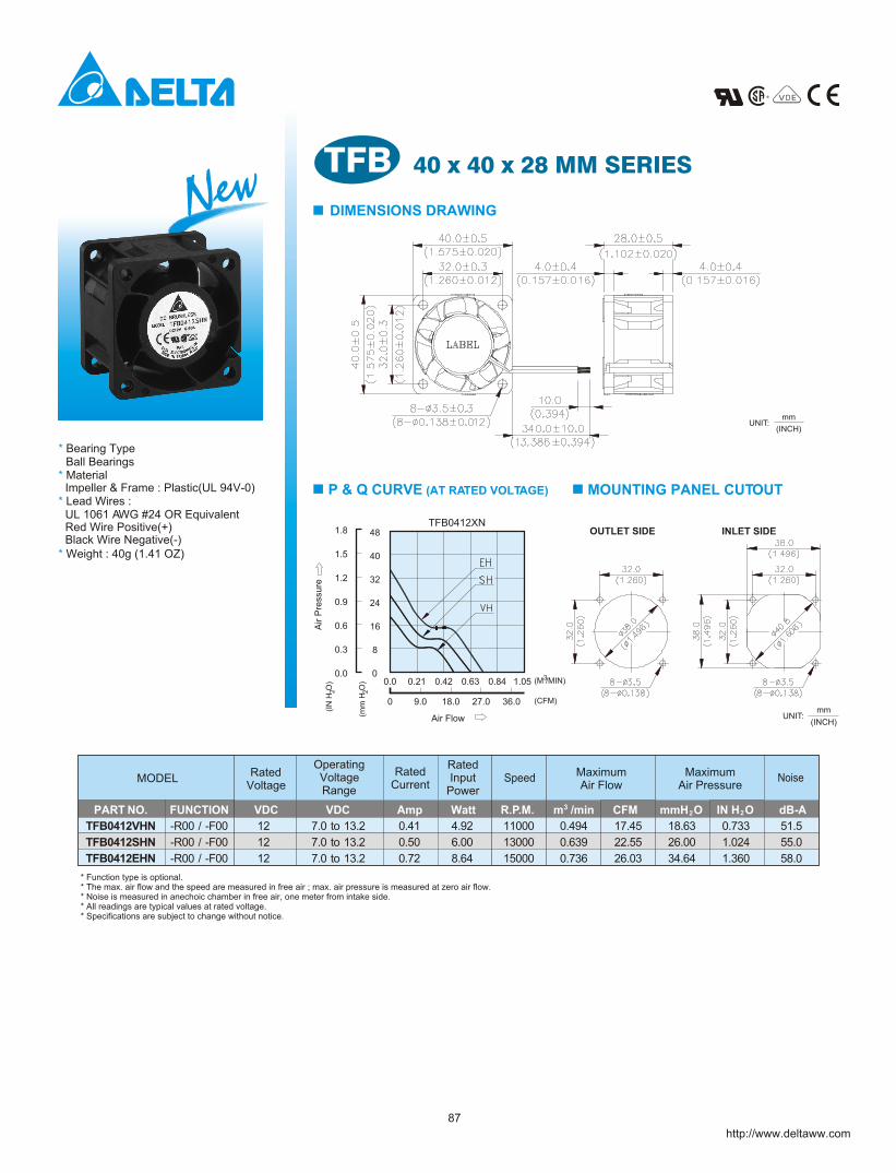
40 x 40 x 28 MM SERIESTFB DIMENSIONS DRAWING
mm
(INCH)UNIT:
P & Q CURVE (AT RATED VOLTAGE) MOUNTING PANEL CUTOUT
mm
(INCH)UNIT:
OUTLET SIDE INLET SIDE
* Bearing Type
* Lead Wires :
* Weight : 40g (1.41 OZ)
* Material Ball Bearings
UL 1061 AWG #24 OR EquivalentRed Wire Positive(+)Black Wire Negative(-)
Impeller & Frame : Plastic(UL 94V-0)
OperatingVoltageRange
MODELRated
VoltageMaximumAir Flow
RatedInput
Power
RatedCurrent
Speed MaximumAir Pressure
Noise
* Function type is optional.* The max. air flow and the speed are measured in free air ; max. air pressure is measured at zero air flow.* Noise is measured in anechoic chamber in free air, one meter from intake side.* All readings are typical values at rated voltage.* Specifications are subject to change without notice.
New
http://www.deltaww.com
PART NO. FUNCTION VDC VDC Amp Watt R.P.M. CFM mmH 2O IN H2 O dB-A
TFB0412VHN -R00 / -F00 12 7.0 to 13.2 0.41 4.92 11000 0.494 17.45 18.63 0.733 51.5
TFB0412SHN -R00 / -F00 12 7.0 to 13.2 0.50 6.00 13000 0.639 22.55 26.00 1.024 55.0
TFB0412EHN -R00 / -F00 12 7.0 to 13.2 0.72 8.64 15000 0.736 26.03 34.64 1.360 58.0
1.5
0.3
0.6
0.9
1.2
(IN
H O
)
Air P
ressu
re
2
(mm
H O
)
Air Flow
27.0
0
2
0.0
0
0.0
8
0.42
18.09.0
0.21 0.63
24
16
40
32
(CFM)
(M /MIN)
36.0
0.84 1.05 3
1.8TFB0412XN
48
87
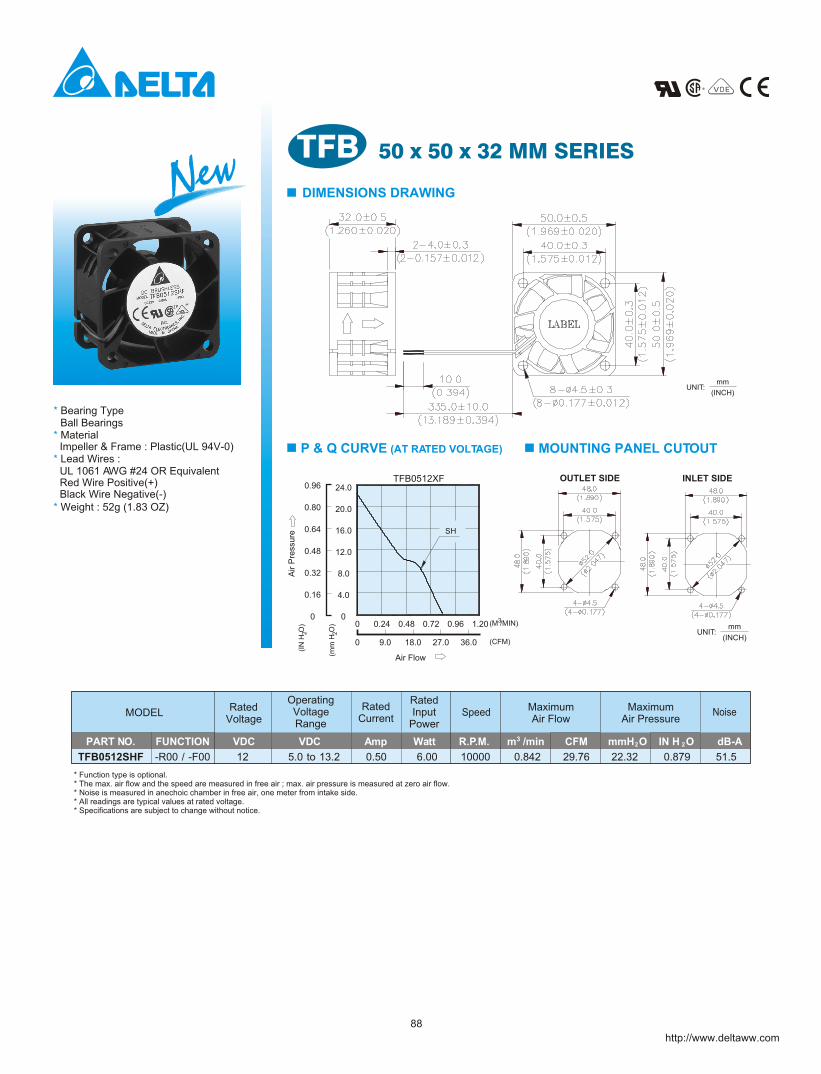
50 x 50 x 32 MM SERIES
DIMENSIONS DRAWING
mm
(INCH)UNIT:
P & Q CURVE (AT RATED VOLTAGE) MOUNTING PANEL CUTOUT
mm
(INCH)UNIT:
OUTLET SIDE INLET SIDE
* Bearing Type
* Lead Wires :
* Weight : 52g (1.83 OZ)
* Material Ball Bearings
UL 1061 AWG #24 OR EquivalentRed Wire Positive(+)Black Wire Negative(-)
Impeller & Frame : Plastic(UL 94V-0)
OperatingVoltageRange
MODELRated
VoltageMaximumAir Flow
RatedInput
Power
RatedCurrent
Speed MaximumAir Pressure
Noise
TFB0512SHF -R00 / -F00 12 5.0 to 13.2 0.50 6.00 10000 0.842 29.76 22.32 0.879 51.5
* Function type is optional.* The max. air flow and the speed are measured in free air ; max. air pressure is measured at zero air flow.* Noise is measured in anechoic chamber in free air, one meter from intake side.* All readings are typical values at rated voltage.* Specifications are subject to change without notice.
NewTFB
http://www.deltaww.com
PART NO. FUNCTION VDC VDC Amp Watt R.P.M. CFM mmH O IN H O dB-A2 2
0.80
0.16
0.32
0.48
0.64
(IN
H O
)
Air P
ressu
re
2
(mm
H O
)
Air Flow
27.0
0
2
0
0
0
4.0
0.48
18.09.0
0.24 0.72
12.0
8.0
20.0
16.0
(CFM)
(M /MIN)
36.0
0.96 1.20 3
0.96TFB0512XF
24.0
SH
88
78
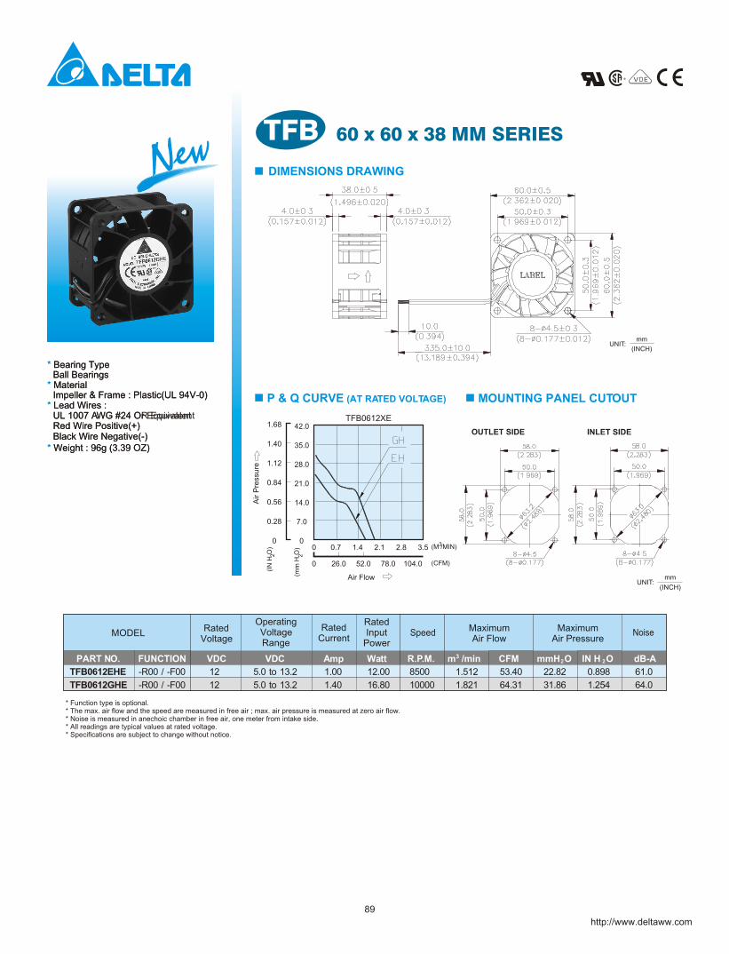
60 x 60 x 38 MM SERIES
DIMENSIONS DRAWING
mm
(INCH)UNIT:
P & Q CURVE (AT RATED VOLTAGE) MOUNTING PANEL CUTOUT
mm
(INCH)UNIT:
OUTLET SIDE INLET SIDE
Impeller & Frame : Plastic(UL 94V-0)
Black Wire Negative(-)Red Wire Positive(+)UL 1007 AWG #24 Or Equivalent
Ball Bearings* Material
* Weight : 96g (3.39 OZ)
* Lead Wires :
* Bearing Type
1.40
1.12
0.84
0.56
0.28
(IN
H O
)
Air P
ressu
re
2
(mm
H O
)
Air Flow
2.1
2
0
0
00
7.0
26.0
0.7
52.0
1.4
14.0
21.0
28.0
35.0
104.0
2.8
78.0
3.5 (M /MIN)
(CFM)
3
1.68TFB0612XE
42.0
NewTFB
http://www.deltaww.com
OperatingVoltageRange
MODELRated
VoltageMaximumAir Flow
RatedInput
Power
RatedCurrent
Speed MaximumAir Pressure
Noise
* Function type is optional.* The max. air flow and the speed are measured in free air ; max. air pressure is measured at zero air flow.* Noise is measured in anechoic chamber in free air, one meter from intake side.* All readings are typical values at rated voltage.* Specifications are subject to change without notice.
PART NO. 3FUNCTION VDC VDC Amp Watt R.P.M. m /min CFM mmH O IN H O dB-A2 2
TFB0612EHE -R00 / -F00 12 5.0 to 13.2 1.00 12.00 8500 1.512 53.40 22.82 0.898 61.0
TFB0612GHE -R00 / -F00 12 5.0 to 13.2 1.40 16.80 10000 1.821 64.31 31.86 1.254 64.0
Impeller & Frame : Plastic(UL 94V-0)
Black Wire Negative(-)Red Wire Positive(+)UL 1007 AWG #24 OR Equivalent
Ball Bearings* Material
* Weight : 96g (3.39 OZ)
* Lead Wires :
* Bearing Type
89
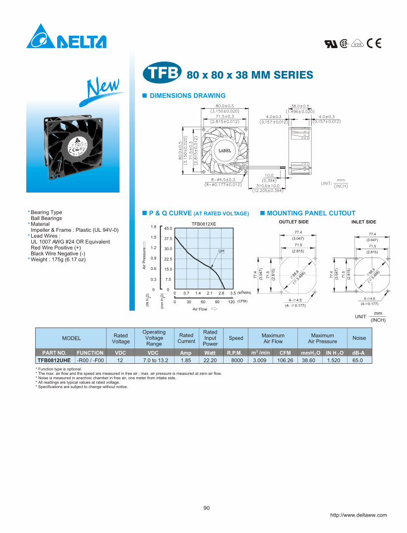
80 x 80 x 38 MM SERIESTFB DIMENSIONS DRAWING
P & Q CURVE (AT RATED VOLTAGE) MOUNTING PANEL CUTOUTBearing TypeBall Bearing Material Impeller & Frame : Plastic (UL 94V-0)Lead Wires :UL 1007 AWG #24 OR EquivalentRed Wire Positive (+)Black Wire Negative (-)Weight : 175g (6.17 oz)
s*
*
*
*
* Function type is optional.* The max. air flow and the speed are measured in free air ; max. air pressure is measured at zero air flow.* Noise is measured in anechoic chamber in free air, one meter from intake side.* All readings are typical values at rated voltage.* Specifications are subject to change without notice.
OperatingVoltageRange
MODELRated
VoltageMaximumAir Flow
RatedInput
Power
RatedCurrent
Speed MaximumAir Pressure
Noise
PART NO. FUNCTION VDC VDC Amp Watt R.P.M. CFM mmH O IN H O dB-A2 2
TFB0812UHE 12 7.0-R00 / -F00 to 13.2 1.85 22.20 8000 3.009 106.26 38.60 1.520 65.0
OUTLET SIDE INLET SIDE
http://www.deltaww.com
New
1.5
Air P
ress
ure
(mm
H O
)
(IN
H O
)
Air Flow
30
7.5
0
2
0
2
0.3
0
0 0.7
37.5
30.0
15.0
22.5
0.6
0.9
1.2
9060
1.4 2.1
120
2.8 3.5 (M /MIN)
(CFM)
3
TFB0812XE45.01.8
UH
(INCH)
mmUNIT:
77
.4
71
.5
(3.0
47
)
(2.8
15
)
(4- 0.177)
4- 4.5
88.6
( 3
.488
)
71.5
(2.815)
(3.047)
77.4
(2.8
15
)
(3.0
47
)
77
.4
71
.5
( 3
.488
)
(4- 0.177)
4- 4.5
88
.6
(3.047)
(2.815)
71.5
77.4
90
* Material
UL 1007 AWG #24 OR Equivalent
Impeller & Frame : Plastic(UL 94V-0)
Black Wire Negative(-)Red Wire Positive(+)
* Weight : 195g (6.88 OZ)
* Lead Wires :
Ball Bearings* Bearing Type
http://www.deltaww.com
NewTFB DIMENSIONS DRAWING
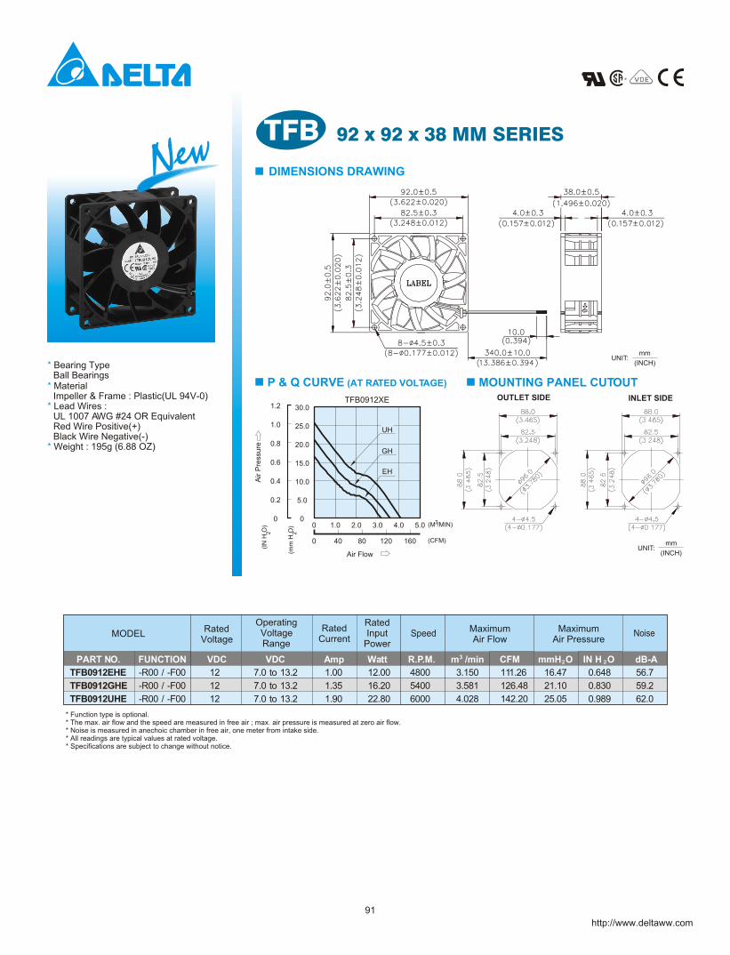
P & Q CURVE (AT RATED VOLTAGE) MOUNTING PANEL CUTOUT
UNIT:(INCH)
mm
mm
(INCH)UNIT:
OUTLET SIDE INLET SIDE
OperatingVoltageRange
MODELRated
VoltageMaximumAir Flow
RatedInput
Power
RatedCurrent
Speed MaximumAir Pressure
Noise
* Function type is optional.* The max. air flow and the speed are measured in free air ; max. air pressure is measured at zero air flow.* Noise is measured in anechoic chamber in free air, one meter from intake side.* All readings are typical values at rated voltage.* Specifications are subject to change without notice.
PART NO. FUNCTION VDC VDC Amp Watt R.P.M. CFM mmH O IN H O dB-A2 2
TFB0912EHE -R00 / -F00 12 7.0 to 13.2 1.00 12.00 4800 3.150 111.26 16.47 0.648 56.7
TFB0912GHE -R00 / -F00 12 7.0 to 13.2 1.35 16.20 5400 3.581 126.48 21.10 0.830 59.2
TFB0912UHE -R00 / -F00 12 7.0 to 13.2 1.90 22.80 6000 4.028 142.20 25.05 0.989 62.0
92 x 92 x 38 MM SERIES
91
UH
GH
EH
Air P
ress
ure
(mm
H O
)
(IN
H O
)
Air Flow
40
5.0
0
2
0
2
0.2
0
0 1.0
25.0
20.0
10.0
15.0
0.4
0.6
0.8
12080
2.0 3.0
160
4.0 5.0 (M /MIN)
(CFM)
3
TFB0912XE30.01.2
1.0
92
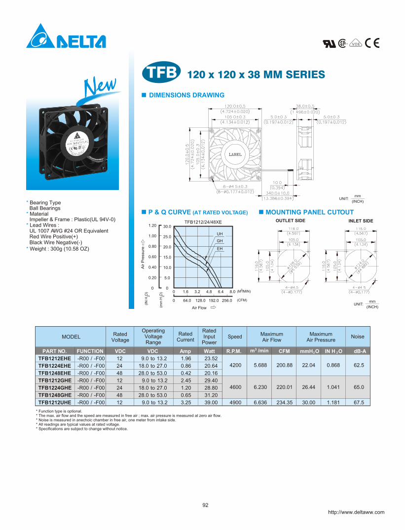
120 x 120 x 38 MM SERIES
DIMENSIONS DRAWING
P & Q CURVE (AT RATED VOLTAGE) MOUNTING PANEL CUTOUT
* Function type is optional.* The max. air flow and the speed are measured in free air ; max. air pressure is measured at zero air flow.* Noise is measured in anechoic chamber in free air, one meter from intake side.* All readings are typical values at rated voltage.* Specifications are subject to change without notice.
OperatingVoltageRange
MODELRated
VoltageMaximumAir Flow
RatedInput
Power
RatedCurrent
Speed MaximumAir Pressure
Noise
(INCH)
mm
mm
(INCH)UNIT:
OUTLET SIDE INLET SIDE
NewTFB
http://www.deltaww.com
Impeller & Frame : Plastic(UL 94V-0)
Black Wire Negative(-)Red Wire Positive(+)UL 1007 AWG #24 OR Equivalent
Ball Bearings* Material
* Weight : 300g (10.58 OZ)
* Lead Wires :
* Bearing TypeUNIT:
PART NO. FUNCTION VDC VDC Amp Watt R.P.M. CFM mmH O IN H O dB-A2 2
TFB1212EHE -R00 / -F00 12 9.0 to 13.2 1.96 23.52
4200 5.688 200.88 22.04 0.868 62.5TFB1224EHE -R00 / -F00 24 18.0 to 27.0 0.86 20.64
TFB1248EHE -R00 / -F00 48 28.0 to 53.0 0.42 20.16
TFB1212GHE -R00 / -F00 12 9.0 to 13.2 2.45 29.40
4600 6.230 220.01 26.44 1.041 65.0TFB1224GHE -R00 / -F00 24 18.0 to 27.0 1.20 28.80
TFB1248GHE -R00 / -F00 48 28.0 to 53.0 0.65 31.20
TFB1212UHE -R00 / -F00 12 9.0 to 13.2 3.25 39.00 4900 6.636 234.35 30.00 1.181 67.5
GH
EH
UH1.00
Air P
ress
ure
(IN
H O
)
(mm
H O
)
Air Flow
64.0
5.0
0
2
0
2
0.20
0
0 1.6
25.0
20.0
10.0
15.0
0.40
0.60
0.80
192.0128.0
3.2 4.8
256.0
6.4 8.0 3
TFB1212/24/48XE30.01.20
(M /MIN)
(CFM)
![MODELL ELEMENTS RUND [RLU] - skantherm€¦ · ELEMENTS RUND [RLU] Maße in mm | Dimensions en mm | Dimensions in mm | Maten en mm | Dimensioni in mm DEUTSCH | FRANÇAIS | ENGLISH](https://img.pdfslide.tips/doc/110x75/602065805d0fbb042850cc5e/modell-elements-rund-rlu-skantherm-elements-rund-rlu-mae-in-mm-dimensions.jpg)