Embed Size (px)
Citation preview

Металлопрокат и трубыпо стандартам
DIN, EN, ASTM
Поставляем металлопрокат по стандарту ASME 16.48
Стандарт предоставлен исключительно для ознакомления
Для заказа металлопрокатаили получения консультацииобращайтесь по следующим контактам:
Россия:
Беларусь:
Казахстан:
+7 (495) 134-41-64
+375 (29) 232-97-79
+7 (7172) 72-76-96
www.emk.bz [email protected]
A N A M E R I C A N N A T I O N A L S T A N D A R D
ASME B16.48-2010(Revision of ASME B16.48-2005)
Line Blanks
INTENTIONALLY LEFT BLANK
标准分享网 www.bzfxw.com 免费下载
ASME B16.48-2010(Revision of ASME B16.48-2005)
Line Blanks
A N A M E R I C A N N A T I O N A L S T A N D A R D
Three Park Avenue • New York, NY • 10016 USA
Date of Issuance: October 14, 2010
The next edition of this Standard is scheduled for publication in 2015. There will be no addendaissued to this edition.
ASME issues written replies to inquiries concerning Interpretations of technical aspects of thisStandard. Interpretations are published on the ASME Web site under the Committee Pages athttp://cstools.asme.org as they are issued.
Items issued as errata to this edition are published on the ASME Web site under the CommitteePages at http://cstools.asme.org.
ASME is the registered trademark of The American Society of Mechanical Engineers.
This code or standard was developed under procedures accredited as meeting the criteria for American NationalStandards. The Standards Committee that approved the code or standard was balanced to ensure that individuals fromcompetent and concerned interests have had an opportunity to participate. The proposed code or standard was madeavailable for public review and comment that provides an opportunity for additional public input from industry, academia,regulatory agencies, and the public-at-large.
ASME does not “approve,” “rate,” or “endorse” any item, construction, proprietary device, or activity.ASME does not take any position with respect to the validity of any patent rights asserted in connection with any
items mentioned in this document and does not undertake to insure anyone utilizing a standard against liability forinfringement of any applicable letters patent, nor assume any such liability. Users of a code or standard are expresslyadvised that determination of the validity of any such patent rights, and the risk of infringement of such rights, isentirely their own responsibility.
Participation by federal agency representative(s) or person(s) affiliated with industry is not to be interpreted asgovernment or industry endorsement of this code or standard.
ASME accepts responsibility for only those interpretations of this document issued in accordance with the establishedASME procedures and policies, which precludes the issuance of interpretations by individuals.
No part of this document may be reproduced in any form,in an electronic retrieval system or otherwise,
without the prior written permission of the publisher.
The American Society of Mechanical EngineersThree Park Avenue, New York, NY 10016-5990
Copyright © 2010 byTHE AMERICAN SOCIETY OF MECHANICAL ENGINEERS
All rights reservedPrinted in U.S.A.
标准分享网 www.bzfxw.com 免费下载
www.bzfxw.com
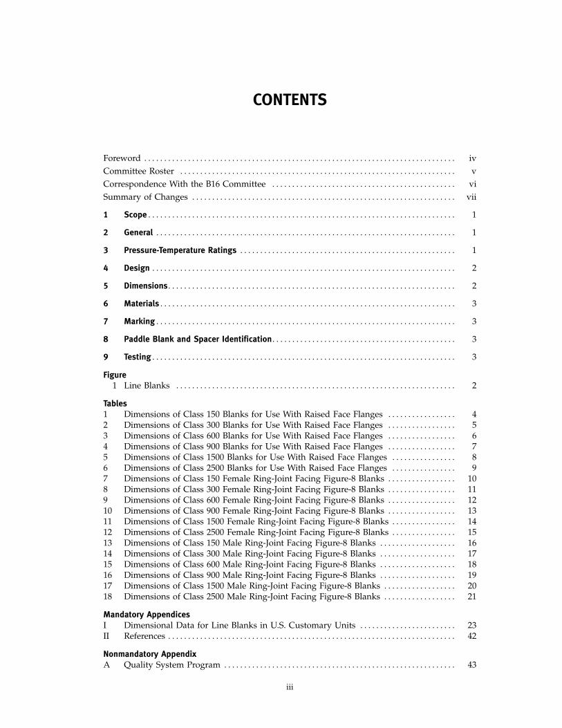
CONTENTS
Foreword . . . . . . . . . . . . . . . . . . . . . . . . . . . . . . . . . . . . . . . . . . . . . . . . . . . . . . . . . . . . . . . . . . . . . . . . . . . . . . ivCommittee Roster . . . . . . . . . . . . . . . . . . . . . . . . . . . . . . . . . . . . . . . . . . . . . . . . . . . . . . . . . . . . . . . . . . . . . vCorrespondence With the B16 Committee . . . . . . . . . . . . . . . . . . . . . . . . . . . . . . . . . . . . . . . . . . . . . . viSummary of Changes . . . . . . . . . . . . . . . . . . . . . . . . . . . . . . . . . . . . . . . . . . . . . . . . . . . . . . . . . . . . . . . . . . vii
1 Scope . . . . . . . . . . . . . . . . . . . . . . . . . . . . . . . . . . . . . . . . . . . . . . . . . . . . . . . . . . . . . . . . . . . . . . . . . . . . . 1
2 General . . . . . . . . . . . . . . . . . . . . . . . . . . . . . . . . . . . . . . . . . . . . . . . . . . . . . . . . . . . . . . . . . . . . . . . . . . . 1
3 Pressure-Temperature Ratings . . . . . . . . . . . . . . . . . . . . . . . . . . . . . . . . . . . . . . . . . . . . . . . . . . . . . . 1
4 Design . . . . . . . . . . . . . . . . . . . . . . . . . . . . . . . . . . . . . . . . . . . . . . . . . . . . . . . . . . . . . . . . . . . . . . . . . . . . 2
5 Dimensions. . . . . . . . . . . . . . . . . . . . . . . . . . . . . . . . . . . . . . . . . . . . . . . . . . . . . . . . . . . . . . . . . . . . . . . . 2
6 Materials . . . . . . . . . . . . . . . . . . . . . . . . . . . . . . . . . . . . . . . . . . . . . . . . . . . . . . . . . . . . . . . . . . . . . . . . . . 3
7 Marking . . . . . . . . . . . . . . . . . . . . . . . . . . . . . . . . . . . . . . . . . . . . . . . . . . . . . . . . . . . . . . . . . . . . . . . . . . . 3
8 Paddle Blank and Spacer Identification. . . . . . . . . . . . . . . . . . . . . . . . . . . . . . . . . . . . . . . . . . . . . . 3
9 Testing . . . . . . . . . . . . . . . . . . . . . . . . . . . . . . . . . . . . . . . . . . . . . . . . . . . . . . . . . . . . . . . . . . . . . . . . . . . . 3
Figure1 Line Blanks . . . . . . . . . . . . . . . . . . . . . . . . . . . . . . . . . . . . . . . . . . . . . . . . . . . . . . . . . . . . . . . . . . . . . . 2
Tables1 Dimensions of Class 150 Blanks for Use With Raised Face Flanges . . . . . . . . . . . . . . . . . 42 Dimensions of Class 300 Blanks for Use With Raised Face Flanges . . . . . . . . . . . . . . . . . 53 Dimensions of Class 600 Blanks for Use With Raised Face Flanges . . . . . . . . . . . . . . . . . 64 Dimensions of Class 900 Blanks for Use With Raised Face Flanges . . . . . . . . . . . . . . . . . 75 Dimensions of Class 1500 Blanks for Use With Raised Face Flanges . . . . . . . . . . . . . . . . 86 Dimensions of Class 2500 Blanks for Use With Raised Face Flanges . . . . . . . . . . . . . . . . 97 Dimensions of Class 150 Female Ring-Joint Facing Figure-8 Blanks . . . . . . . . . . . . . . . . . 108 Dimensions of Class 300 Female Ring-Joint Facing Figure-8 Blanks . . . . . . . . . . . . . . . . . 119 Dimensions of Class 600 Female Ring-Joint Facing Figure-8 Blanks . . . . . . . . . . . . . . . . . 1210 Dimensions of Class 900 Female Ring-Joint Facing Figure-8 Blanks . . . . . . . . . . . . . . . . . 1311 Dimensions of Class 1500 Female Ring-Joint Facing Figure-8 Blanks . . . . . . . . . . . . . . . . 1412 Dimensions of Class 2500 Female Ring-Joint Facing Figure-8 Blanks . . . . . . . . . . . . . . . . 1513 Dimensions of Class 150 Male Ring-Joint Facing Figure-8 Blanks . . . . . . . . . . . . . . . . . . . 1614 Dimensions of Class 300 Male Ring-Joint Facing Figure-8 Blanks . . . . . . . . . . . . . . . . . . . 1715 Dimensions of Class 600 Male Ring-Joint Facing Figure-8 Blanks . . . . . . . . . . . . . . . . . . . 1816 Dimensions of Class 900 Male Ring-Joint Facing Figure-8 Blanks . . . . . . . . . . . . . . . . . . . 1917 Dimensions of Class 1500 Male Ring-Joint Facing Figure-8 Blanks . . . . . . . . . . . . . . . . . . 2018 Dimensions of Class 2500 Male Ring-Joint Facing Figure-8 Blanks . . . . . . . . . . . . . . . . . . 21
Mandatory AppendicesI Dimensional Data for Line Blanks in U.S. Customary Units . . . . . . . . . . . . . . . . . . . . . . . . 23II References . . . . . . . . . . . . . . . . . . . . . . . . . . . . . . . . . . . . . . . . . . . . . . . . . . . . . . . . . . . . . . . . . . . . . . . . 42
Nonmandatory AppendixA Quality System Program . . . . . . . . . . . . . . . . . . . . . . . . . . . . . . . . . . . . . . . . . . . . . . . . . . . . . . . . . . 43
iii
www.bzfxw.com
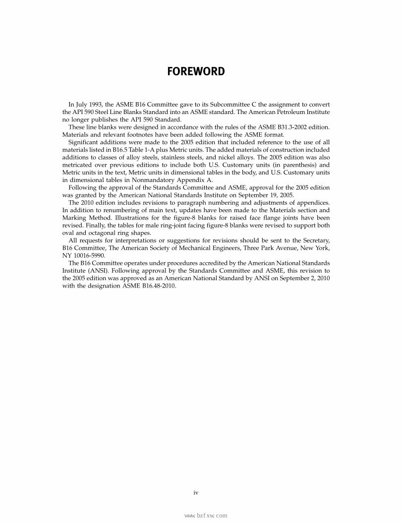
FOREWORD
In July 1993, the ASME B16 Committee gave to its Subcommittee C the assignment to convertthe API 590 Steel Line Blanks Standard into an ASME standard. The American Petroleum Instituteno longer publishes the API 590 Standard.
These line blanks were designed in accordance with the rules of the ASME B31.3-2002 edition.Materials and relevant footnotes have been added following the ASME format.
Significant additions were made to the 2005 edition that included reference to the use of allmaterials listed in B16.5 Table 1-A plus Metric units. The added materials of construction includedadditions to classes of alloy steels, stainless steels, and nickel alloys. The 2005 edition was alsometricated over previous editions to include both U.S. Customary units (in parenthesis) andMetric units in the text, Metric units in dimensional tables in the body, and U.S. Customary unitsin dimensional tables in Nonmandatory Appendix A.
Following the approval of the Standards Committee and ASME, approval for the 2005 editionwas granted by the American National Standards Institute on September 19, 2005.
The 2010 edition includes revisions to paragraph numbering and adjustments of appendices.In addition to renumbering of main text, updates have been made to the Materials section andMarking Method. Illustrations for the figure-8 blanks for raised face flange joints have beenrevised. Finally, the tables for male ring-joint facing figure-8 blanks were revised to support bothoval and octagonal ring shapes.
All requests for interpretations or suggestions for revisions should be sent to the Secretary,B16 Committee, The American Society of Mechanical Engineers, Three Park Avenue, New York,NY 10016-5990.
The B16 Committee operates under procedures accredited by the American National StandardsInstitute (ANSI). Following approval by the Standards Committee and ASME, this revision tothe 2005 edition was approved as an American National Standard by ANSI on September 2, 2010with the designation ASME B16.48-2010.
iv
标准分享网 www.bzfxw.com 免费下载

www.bzfxw.com
ASME B16 COMMITTEEStandardization of Valves,
Flanges, Fittings, and Gaskets(The following is the roster of the Committee at the time of approval of this Standard.)
STANDARDS COMMITTEE OFFICERS
W. B. Bedesem, ChairM. L. Nayyar, Vice Chair
D. R. Sharp, Secretary
STANDARDS COMMITTEE PERSONNEL
R. W. Barnes, Anric Enterprises, Inc.W. B. Bedesem, ConsultantD. F. Buccicone, Elkhart Products Corp.A. M. Cheta, Royal Dutch ShellM. A. Clark, Nibco, Inc.G. A. Cuccio, Capitol Manufacturing Co.C. E. Davila, Crane Energy Flow SolutionsD. R. Frikken, Becht Engineering Co.R. P. Griffiths, U.S. Coast GuardM. L. Henderson, Tiec, Inc.G. A. Jolly, Vogt Valves/Flowserve
SUBCOMMITTEE C — STEEL FLANGES AND FLANGED FITTINGS
C. E. Davila, Chair, Crane Energy Flow SolutionsA. P. Maslowski, Secretary, The American Society of Mechanical
EngineersA. Appleton, Alloy Stainless Products Co., Inc.W. B. Bedesem, ConsultantW. J. Birkholz, Flowline Division, Markovitz Enterprises, Inc.A. M. Cheta, Royal Dutch ShellB. Dennis, Kerkau ManufacturingJ. P. Ellenberger, ConsultantD. R. Frikken, Becht Engineering Co.M. L. Henderson, Tiec, Inc.C. L. Henley, Black & Veatch
v
M. Katcher, Haynes InternationalW. N. McLean, B & L EngineeringT. A. McMahon, Emerson Process ManagementM. L. Nayyar, Bechtel Power Corp.W. H. Patrick, The Dow Chemical Co.R. A. Schmidt, Hackney Ladish, Inc.D. R. Sharp, The American Society of Mechanical EngineersH. R. Sonderegger, ConsultantW. M. Stephan, Flexitallic LPF. R. Volgstadt, Volgstadt & Associates, Inc.D. A. Williams, Southern Company ServicesR. T. Faircloth, Alternate, Cameron Valves & Measurement
J. R. Holstrom, Val-Matic Valve & Manufacturing Corp.M. Katcher, Haynes InternationalW. N. McLean, B & L EngineeringM. L. Nayyar, Bechtel Power Corp.W. H. Patrick, The Dow Chemical Co.T. V. Ramakrishnan, Forged Vessel ConnectionsR. A. Schmidt, Hackney Ladish, Inc.D. E. Tezzo, The Newdell Co.J. P. Tucker, FlowserveM. M. Zaidi, Jacobs Engineering Group, Inc.E. Gulgun, Contributing Member, International Standard Valve, Inc.G. Hailegiorgis, Contributing Member, Ameriforge Group, Inc.R. T. Faircloth, Alternate, Cameron Valves & Measurement
www.bzfxw.com
CORRESPONDENCE WITH THE B16 COMMITTEE
General. ASME Standards are developed and maintained with the intent to represent theconsensus of concerned interests. As such, users of this Standard may interact with the Committeeby requesting interpretations, proposing revisions, and attending Committee meetings. Corre-spondence should be addressed to:
Secretary, B16 Standards CommitteeThe American Society of Mechanical EngineersThree Park AvenueNew York, NY 10016-5990
As an alternative, inquiries may be submitted via e-mail to [email protected] Revisions. Revisions are made periodically to the Standard to incorporate changes
that appear necessary or desirable, as demonstrated by the experience gained from the applicationof the Standard. Approved revisions will be published periodically.
The Committee welcomes proposals for revisions to this Standard. Such proposals should beas specific as possible, citing the paragraph number(s), the proposed wording, and a detaileddescription of the reasons for the proposal, including any pertinent documentation.
Interpretations. Upon request, the B16 Committee will render an interpretation of any require-ment of the Standard. Interpretations can only be rendered in response to a written request sentto the Secretary of the B16 Standards Committee.
The request for interpretation should be clear and unambiguous. It is further recommendedthat the inquirer submit his/her request in the following format:
Subject: Cite the applicable paragraph number(s) and the topic of the inquiry.Edition: Cite the applicable edition of the Standard for which the interpretation is
being requested.Question: Phrase the question as a request for an interpretation of a specific requirement
suitable for general understanding and use, not as a request for an approvalof a proprietary design or situation. The inquirer may also include any plansor drawings that are necessary to explain the question; however, they shouldnot contain proprietary names or information.
Requests that are not in this format will be rewritten in this format by the Committee priorto being answered, which may inadvertently change the intent of the original request.
ASME procedures provide for reconsideration of any interpretation when or if additionalinformation that might affect an interpretation is available. Further, persons aggrieved by aninterpretation may appeal to the cognizant ASME Committee or Subcommittee. ASME does not“approve,” “certify,” “rate,” or “endorse” any item, construction, proprietary device, or activity.
Attending Committee Meetings. The B16 Standards Committee regularly holds meetings, whichare open to the public. Persons wishing to attend any meeting should contact the Secretary ofthe B16 Standards Committee.
vi
标准分享网 www.bzfxw.com 免费下载
www.bzfxw.com
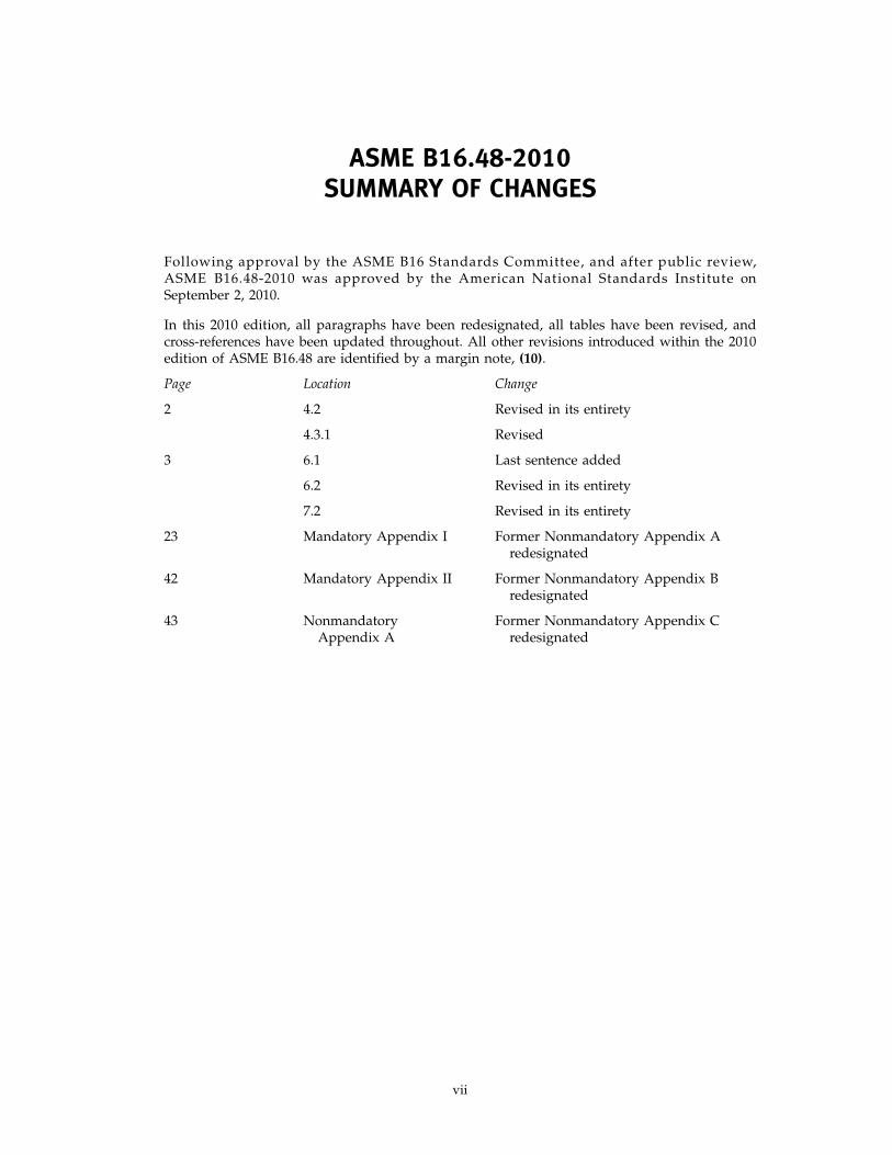
ASME B16.48-2010SUMMARY OF CHANGES
Following approval by the ASME B16 Standards Committee, and after public review,ASME B16.48-2010 was approved by the American National Standards Institute onSeptember 2, 2010.
In this 2010 edition, all paragraphs have been redesignated, all tables have been revised, andcross-references have been updated throughout. All other revisions introduced within the 2010edition of ASME B16.48 are identified by a margin note, (10).
Page Location Change
2 4.2 Revised in its entirety
4.3.1 Revised
3 6.1 Last sentence added
6.2 Revised in its entirety
7.2 Revised in its entirety
23 Mandatory Appendix I Former Nonmandatory Appendix Aredesignated
42 Mandatory Appendix II Former Nonmandatory Appendix Bredesignated
43 Nonmandatory Former Nonmandatory Appendix CAppendix A redesignated
vii
www.bzfxw.comINTENTIONALLY LEFT BLANK
viii
标准分享网 www.bzfxw.com 免费下载
www.bzfxw.com
ASME B16.48-2010
LINE BLANKS
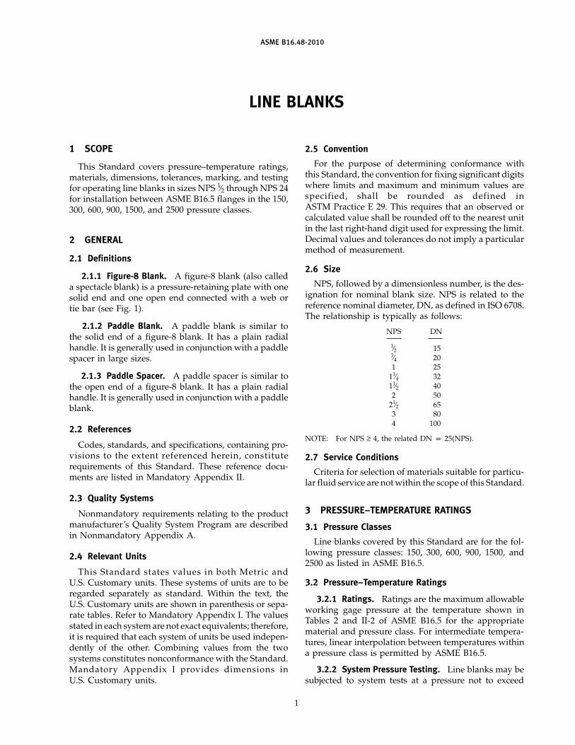
1 SCOPE
This Standard covers pressure–temperature ratings,materials, dimensions, tolerances, marking, and testingfor operating line blanks in sizes NPS 1⁄2 through NPS 24for installation between ASME B16.5 flanges in the 150,300, 600, 900, 1500, and 2500 pressure classes.
2 GENERAL
2.1 Definitions
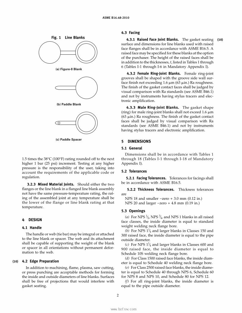
2.1.1 Figure-8 Blank. A figure-8 blank (also calleda spectacle blank) is a pressure-retaining plate with onesolid end and one open end connected with a web ortie bar (see Fig. 1).
2.1.2 Paddle Blank. A paddle blank is similar tothe solid end of a figure-8 blank. It has a plain radialhandle. It is generally used in conjunction with a paddlespacer in large sizes.
2.1.3 Paddle Spacer. A paddle spacer is similar tothe open end of a figure-8 blank. It has a plain radialhandle. It is generally used in conjunction with a paddleblank.
2.2 References
Codes, standards, and specifications, containing pro-visions to the extent referenced herein, constituterequirements of this Standard. These reference docu-ments are listed in Mandatory Appendix II.
2.3 Quality Systems
Nonmandatory requirements relating to the productmanufacturer’s Quality System Program are describedin Nonmandatory Appendix A.
2.4 Relevant Units
This Standard states values in both Metric andU.S. Customary units. These systems of units are to beregarded separately as standard. Within the text, theU.S. Customary units are shown in parenthesis or sepa-rate tables. Refer to Mandatory Appendix I. The valuesstated in each system are not exact equivalents; therefore,it is required that each system of units be used indepen-dently of the other. Combining values from the twosystems constitutes nonconformance with the Standard.Mandatory Appendix I provides dimensions inU.S. Customary units.
1
2.5 Convention
For the purpose of determining conformance withthis Standard, the convention for fixing significant digitswhere limits and maximum and minimum values arespecified, shall be rounded as defined inASTM Practice E 29. This requires that an observed orcalculated value shall be rounded off to the nearest unitin the last right-hand digit used for expressing the limit.Decimal values and tolerances do not imply a particularmethod of measurement.
2.6 Size
NPS, followed by a dimensionless number, is the des-ignation for nominal blank size. NPS is related to thereference nominal diameter, DN, as defined in ISO 6708.The relationship is typically as follows:
NPS DN
1⁄2 153⁄4 201 25
11⁄4 3211⁄2 402 50
21⁄2 653 804 100
NOTE: For NPS ≥ 4, the related DN p 25(NPS).
2.7 Service Conditions
Criteria for selection of materials suitable for particu-lar fluid service are not within the scope of this Standard.
3 PRESSURE–TEMPERATURE RATINGS
3.1 Pressure Classes
Line blanks covered by this Standard are for the fol-lowing pressure classes: 150, 300, 600, 900, 1500, and2500 as listed in ASME B16.5.
3.2 Pressure–Temperature Ratings
3.2.1 Ratings. Ratings are the maximum allowableworking gage pressure at the temperature shown inTables 2 and II-2 of ASME B16.5 for the appropriatematerial and pressure class. For intermediate tempera-tures, linear interpolation between temperatures withina pressure class is permitted by ASME B16.5.
3.2.2 System Pressure Testing. Line blanks may besubjected to system tests at a pressure not to exceed
www.bzfxw.com
(10)
ASME B16.48-2010
Fig. 1 Line Blanks
(a) Figure-8 Blank
(b) Paddle Blank
(c) Paddle Spacer
1.5 times the 38°C (100°F) rating rounded off to the nexthigher 1 bar (25 psi) increment. Testing at any higherpressure is the responsibility of the user, taking intoaccount the requirements of the applicable code orregulation.
3.2.3 Mixed Material Joints. Should either the twoflanges or the line blank in a flanged line blank assemblynot have the same pressure-temperature rating, the rat-ing of the assembled joint at any temperature shall bethe lower of the flange or line blank rating at thattemperature.
4 DESIGN
4.1 Handle
The handle or web (tie bar) may be integral or attachedto the line blank or spacer. The web and its attachmentshall be capable of supporting the weight of the blankor spacer in all orientations without permanent defor-mation to the web.
4.2 Edge Preparation
In addition to machining, flame, plasma, saw cutting,or press punching are acceptable methods for formingthe inside and outside diameters of line blanks. Surfacesshall be free of projections that would interfere withgasket seating.
2
4.3 Facing
4.3.1 Raised Face Joint Blanks. The gasket seatingsurface and dimensions for line blanks used with raisedface flanges shall be in accordance with ASME B16.5. Araised face may be specified for these blanks at the optionof the purchaser. The height of the raised faces shall bein addition to the thicknesses, t, listed in Tables 1 through6 (Tables I-1 through I-6 in Mandatory Appendix I).
4.3.2 Female Ring-Joint Blanks. Female ring-jointgrooves shall be shaped with the groove side wall sur-face finish not exceeding 1.6 �m (63 �in.) Ra roughness.The finish of the gasket contact faces shall be judged byvisual comparison with Ra standards (see ASME B46.1)and not by instruments having stylus tracers and elec-tronic amplification.
4.3.3 Male Ring-Joint Blanks. The gasket shape(ring) for male ring-joint blanks shall not exceed 1.6 �m(63 �in.) Ra roughness. The finish of the gasket contactfaces shall be judged by visual comparison with Rastandards (see ASME B46.1) and not by instrumentshaving stylus tracers and electronic amplification.
5 DIMENSIONS
5.1 General
Dimensions shall be in accordance with Tables 1through 18 (Tables I-1 through I-18 of MandatoryAppendix I).
5.2 Tolerances
5.2.1 Facing Tolerances. Tolerances for facings shallbe in accordance with ASME B16.5.
5.2.2 Thickness Tolerances. Thickness tolerancesare
NPS 18 and smaller −zero + 3.0 mm (0.12 in.)NPS 20 and larger −zero + 4.8 mm (0.19 in.)
5.3 Openings
(a) For NPS 1⁄2, NPS 3⁄4, and NPS 1 blanks in all raisedface classes, the inside diameter is equal to standardweight welding neck flange bore.
(b) For NPS 11⁄4 and larger blanks in Classes 150 and300 raised face, the inside diameter is equal to the pipeoutside diameter.
(c) For NPS 11⁄4 and larger blanks in Classes 600 and900 raised face, the inside diameter is equal toSchedule 10S welding neck flange bore.
(d) For Class 1500 raised face blanks, the inside diam-eter is equal to Schedule 40 welding neck flange bore.
(e) For Class 2500 raised face blanks, the inside diame-ter is equal to Schedule 40 through NPS 6, Schedule 60for NPS 8 and NPS 10, and Schedule 80 for NPS 12.
(f) For all ring-joint blanks, the inside diameter isequal to the pipe outside diameter.
(10)
标准分享网 www.bzfxw.com 免费下载

www.bzfxw.com
(10)
(10)
ASME B16.48-2010
(g) Dimensions are based upon concentric installationof spiral wound gaskets with inner rings as required byASME B16.20 and conform to the maximum permittedbore of ASME B16.5 welding neck flanges described inTable 16 of ASME B16.20.
5.4 Facing Finish
Facing finish shall be in accordance with ASME B16.5,para. 6.4.5.
6 MATERIALS
6.1 General
Materials for line blanks shall be in accordance withASME B16.5, Table 1A, and shall include material restric-tions cited in notes to Tables 2 or II-2 of ASME B16.5.Recommended bolting materials for flange-blankassemblies are listed in ASME B16.5, Table 1B. For mate-rials manufactured to editions of the material specifica-tion other than those listed in Appendix III ofASME B16.5, refer to para. 6.2.
Criteria for the selection of materials are not withinthe scope of this Standard.
6.2 Materials Manufactured to Other Editions
Materials may meet the requirements of material spec-ification editions other than those listed in Appendix IIIof ASME B16.5, provided
(a) the materials are the same specification, grade,type, class, alloy, and heat-treated condition, asapplicable
(b) the line blank manufacturer certifies that therequirements of the edition of the specification listed inAppendix III of ASME B16.5 have been met
7 MARKING
7.1 General
(a) Line blanks shall be marked as follows:(1) manufacturer’s name or trademark
3
(2) material, specification, and grade or class(3) pressure class(4) B16(5) size (NPS)(6) ring number (if applicable)
(b) Where space does not permit all of the abovemarkings, they may be omitted in the reverse ordergiven in para. 7.1(a).
(c) The B16 designation may be applied only whenthe line blank has been manufactured in full confor-mance with this Standard.
7.2 Marking Method
The marking shall be applied by steel stamping orother marking device that leaves a legible imprint. Whenmarking on the blind portion of the blanks, low stressmarking shall be used and shall not impinge on thegasket seating surface.
8 PADDLE BLANK AND SPACER IDENTIFICATION
8.1 Paddle Handles
In order to differentiate between an installed paddlespacer and a paddle blank, it is required that there bean externally visible distinction between the two asrequired by paras. 8.2 and 8.3.
8.2 Paddle Blank Handles
Handles for paddle blanks shall be solid with noopenings.
8.3 Paddle Spacer Handles
Handles for paddle spacers shall have a single throughindicator hole located near the end of the handle. Thehole diameter shall not be less than 12 mm (1⁄2 in.).
9 TESTING
Line blanks are not required to be pressure tested.
(10)
www.bzfxw.com
ASME B16.48-2010
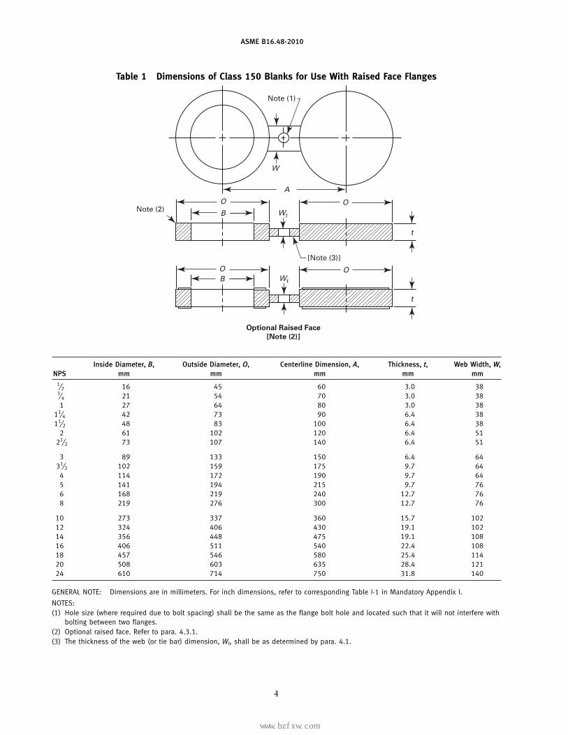
Table 1 Dimensions of Class 150 Blanks for Use With Raised Face Flanges
Note (1)
A
O
BO
t
Note (2)
[Note (3)]
t
W
W
OB
O
t
Optional Raised Face
[Note (2)]
tW
Inside Diameter, B, Outside Diameter, O, Centerline Dimension, A, Thickness, t, Web Width, W,NPS mm mm mm mm mm
1⁄2 16 45 60 3.0 383⁄4 21 54 70 3.0 381 27 64 80 3.0 38
11⁄4 42 73 90 6.4 3811⁄2 48 83 100 6.4 38
2 61 102 120 6.4 5121⁄2 73 107 140 6.4 51
3 89 133 150 6.4 6431⁄2 102 159 175 9.7 64
4 114 172 190 9.7 645 141 194 215 9.7 766 168 219 240 12.7 768 219 276 300 12.7 76
10 273 337 360 15.7 10212 324 406 430 19.1 10214 356 448 475 19.1 10816 406 511 540 22.4 10818 457 546 580 25.4 11420 508 603 635 28.4 12124 610 714 750 31.8 140
GENERAL NOTE: Dimensions are in millimeters. For inch dimensions, refer to corresponding Table I-1 in Mandatory Appendix I.
NOTES:(1) Hole size (where required due to bolt spacing) shall be the same as the flange bolt hole and located such that it will not interfere with
bolting between two flanges.(2) Optional raised face. Refer to para. 4.3.1.(3) The thickness of the web (or tie bar) dimension, Wt, shall be as determined by para. 4.1.
4
标准分享网 www.bzfxw.com 免费下载
www.bzfxw.com
ASME B16.48-2010
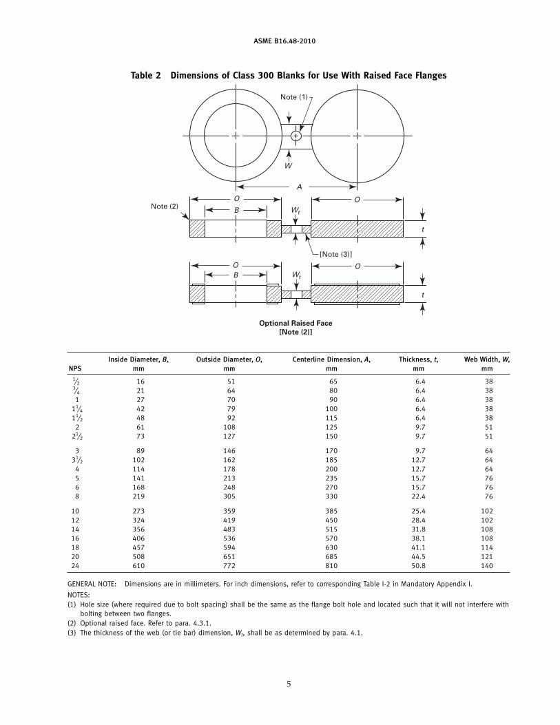
Table 2 Dimensions of Class 300 Blanks for Use With Raised Face Flanges
Note (1)
A
O
BO
t
Note (2)
[Note (3)]
t
W
W
OB
O
t
Optional Raised Face
[Note (2)]
tW
Inside Diameter, B, Outside Diameter, O, Centerline Dimension, A, Thickness, t, Web Width, W,NPS mm mm mm mm mm
1⁄2 16 51 65 6.4 383⁄4 21 64 80 6.4 381 27 70 90 6.4 38
11⁄4 42 79 100 6.4 3811⁄2 48 92 115 6.4 38
2 61 108 125 9.7 5121⁄2 73 127 150 9.7 51
3 89 146 170 9.7 6431⁄2 102 162 185 12.7 64
4 114 178 200 12.7 645 141 213 235 15.7 766 168 248 270 15.7 768 219 305 330 22.4 76
10 273 359 385 25.4 10212 324 419 450 28.4 10214 356 483 515 31.8 10816 406 536 570 38.1 10818 457 594 630 41.1 11420 508 651 685 44.5 12124 610 772 810 50.8 140
GENERAL NOTE: Dimensions are in millimeters. For inch dimensions, refer to corresponding Table I-2 in Mandatory Appendix I.
NOTES:(1) Hole size (where required due to bolt spacing) shall be the same as the flange bolt hole and located such that it will not interfere with
bolting between two flanges.(2) Optional raised face. Refer to para. 4.3.1.(3) The thickness of the web (or tie bar) dimension, Wt, shall be as determined by para. 4.1.
5
www.bzfxw.com
ASME B16.48-2010
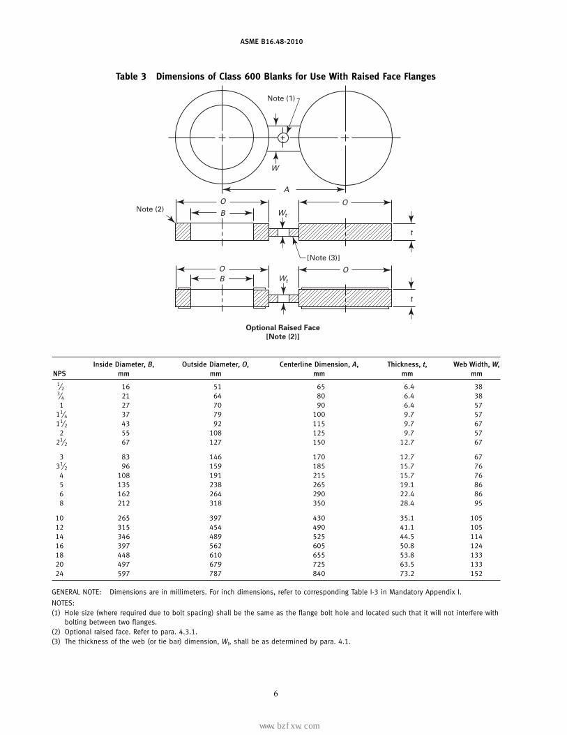
Table 3 Dimensions of Class 600 Blanks for Use With Raised Face Flanges
Note (1)
A
O
BO
t
Note (2)
[Note (3)]
t
W
W
OB
O
t
Optional Raised Face
[Note (2)]
tW
Inside Diameter, B, Outside Diameter, O, Centerline Dimension, A, Thickness, t, Web Width, W,NPS mm mm mm mm mm
1⁄2 16 51 65 6.4 383⁄4 21 64 80 6.4 381 27 70 90 6.4 57
11⁄4 37 79 100 9.7 5711⁄2 43 92 115 9.7 67
2 55 108 125 9.7 5721⁄2 67 127 150 12.7 67
3 83 146 170 12.7 6731⁄2 96 159 185 15.7 76
4 108 191 215 15.7 765 135 238 265 19.1 866 162 264 290 22.4 868 212 318 350 28.4 95
10 265 397 430 35.1 10512 315 454 490 41.1 10514 346 489 525 44.5 11416 397 562 605 50.8 12418 448 610 655 53.8 13320 497 679 725 63.5 13324 597 787 840 73.2 152
GENERAL NOTE: Dimensions are in millimeters. For inch dimensions, refer to corresponding Table I-3 in Mandatory Appendix I.
NOTES:(1) Hole size (where required due to bolt spacing) shall be the same as the flange bolt hole and located such that it will not interfere with
bolting between two flanges.(2) Optional raised face. Refer to para. 4.3.1.(3) The thickness of the web (or tie bar) dimension, Wt, shall be as determined by para. 4.1.
6
标准分享网 www.bzfxw.com 免费下载
www.bzfxw.com
ASME B16.48-2010
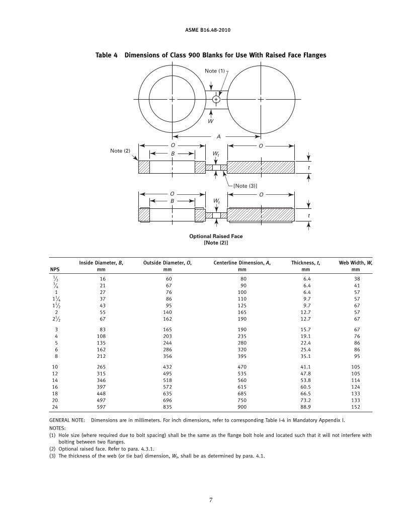
Table 4 Dimensions of Class 900 Blanks for Use With Raised Face Flanges
Note (1)
A
O
BO
t
Note (2)
[Note (3)]
t
W
W
OB
O
t
Optional Raised Face
[Note (2)]
tW
Inside Diameter, B, Outside Diameter, O, Centerline Dimension, A, Thickness, t, Web Width, W,NPS mm mm mm mm mm
1⁄2 16 60 80 6.4 383⁄4 21 67 90 6.4 411 27 76 100 6.4 57
11⁄4 37 86 110 9.7 5711⁄2 43 95 125 9.7 67
2 55 140 165 12.7 5721⁄2 67 162 190 12.7 67
3 83 165 190 15.7 674 108 203 235 19.1 765 135 244 280 22.4 866 162 286 320 25.4 868 212 356 395 35.1 95
10 265 432 470 41.1 10512 315 495 535 47.8 10514 346 518 560 53.8 11416 397 572 615 60.5 12418 448 635 685 66.5 13320 497 696 750 73.2 13324 597 835 900 88.9 152
GENERAL NOTE: Dimensions are in millimeters. For inch dimensions, refer to corresponding Table I-4 in Mandatory Appendix I.
NOTES:(1) Hole size (where required due to bolt spacing) shall be the same as the flange bolt hole and located such that it will not interfere with
bolting between two flanges.(2) Optional raised face. Refer to para. 4.3.1.(3) The thickness of the web (or tie bar) dimension, Wt, shall be as determined by para. 4.1.
7
www.bzfxw.com
ASME B16.48-2010
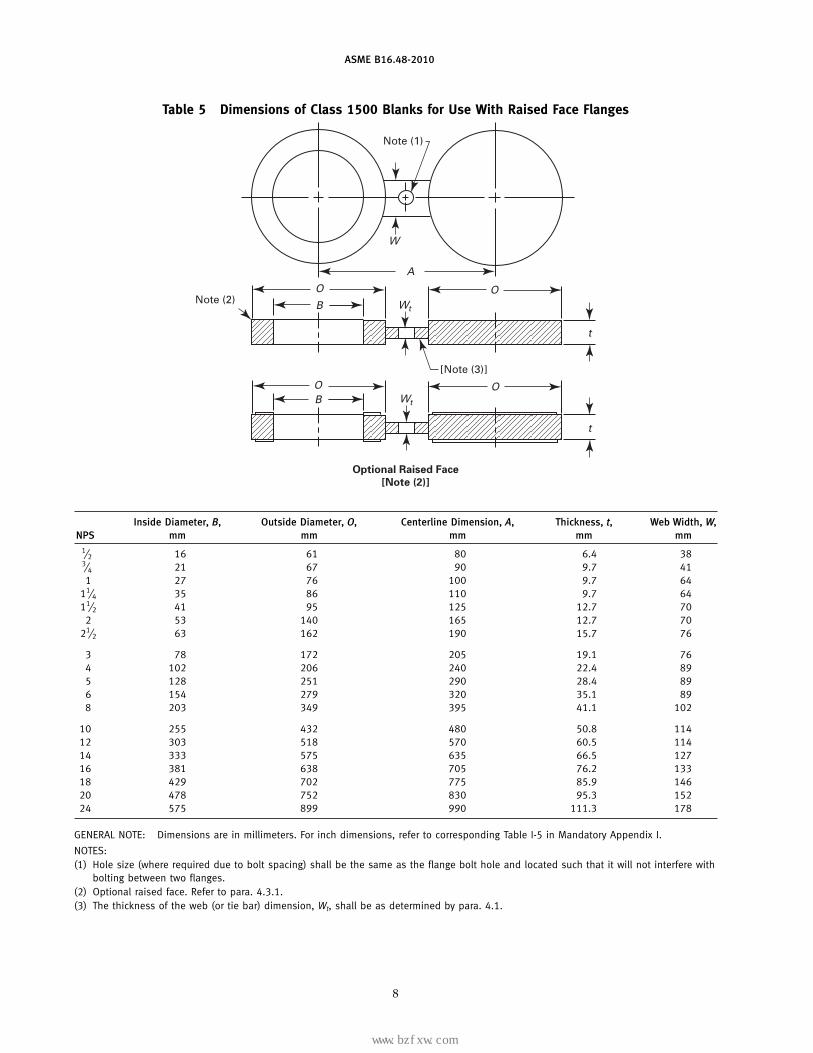
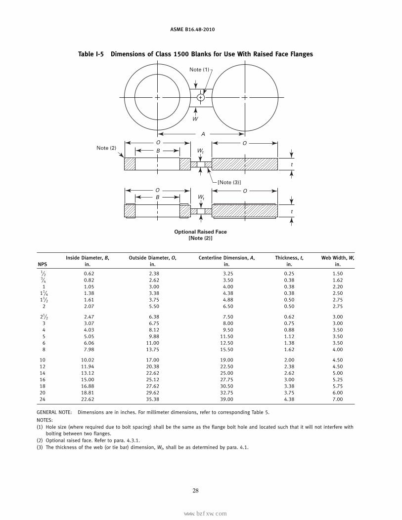
Table 5 Dimensions of Class 1500 Blanks for Use With Raised Face Flanges
Note (1)
A
O
BO
t
Note (2)
[Note (3)]
t
W
W
OB
O
t
Optional Raised Face
[Note (2)]
tW
Inside Diameter, B, Outside Diameter, O, Centerline Dimension, A, Thickness, t, Web Width, W,NPS mm mm mm mm mm
1⁄2 16 61 80 6.4 383⁄4 21 67 90 9.7 411 27 76 100 9.7 64
11⁄4 35 86 110 9.7 6411⁄2 41 95 125 12.7 70
2 53 140 165 12.7 7021⁄2 63 162 190 15.7 76
3 78 172 205 19.1 764 102 206 240 22.4 895 128 251 290 28.4 896 154 279 320 35.1 898 203 349 395 41.1 102
10 255 432 480 50.8 11412 303 518 570 60.5 11414 333 575 635 66.5 12716 381 638 705 76.2 13318 429 702 775 85.9 14620 478 752 830 95.3 15224 575 899 990 111.3 178
GENERAL NOTE: Dimensions are in millimeters. For inch dimensions, refer to corresponding Table I-5 in Mandatory Appendix I.
NOTES:(1) Hole size (where required due to bolt spacing) shall be the same as the flange bolt hole and located such that it will not interfere with
bolting between two flanges.(2) Optional raised face. Refer to para. 4.3.1.(3) The thickness of the web (or tie bar) dimension, Wt, shall be as determined by para. 4.1.
8
标准分享网 www.bzfxw.com 免费下载
www.bzfxw.com
ASME B16.48-2010
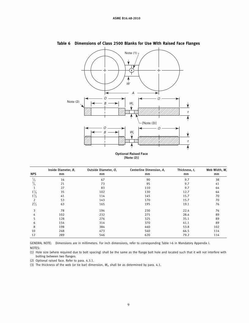
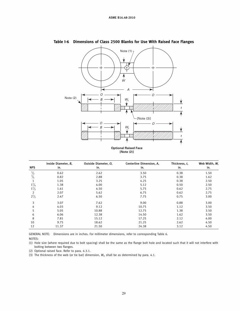
Table 6 Dimensions of Class 2500 Blanks for Use With Raised Face Flanges
Note (1)
A
O
BO
t
Note (2)
[Note (3)]
t
W
W
OB
O
t
Optional Raised Face
[Note (2)]
tW
Inside Diameter, B, Outside Diameter, O, Centerline Dimension, A, Thickness, t, Web Width, W,NPS mm mm mm mm mm
1⁄2 16 67 90 9.7 383⁄4 21 73 95 9.7 411 27 83 110 9.7 64
11⁄4 35 102 130 12.7 6411⁄2 41 114 145 15.7 70
2 53 143 170 15.7 7021⁄2 63 165 195 19.1 76
3 78 194 230 22.4 764 102 232 275 28.4 895 128 276 325 35.1 896 154 314 370 41.1 898 198 384 440 53.8 102
10 248 473 540 66.5 11412 289 546 620 79.2 114
GENERAL NOTE: Dimensions are in millimeters. For inch dimensions, refer to corresponding Table I-6 in Mandatory Appendix I.
NOTES:(1) Hole size (where required due to bolt spacing) shall be the same as the flange bolt hole and located such that it will not interfere with
bolting between two flanges.(2) Optional raised face. Refer to para. 4.3.1.(3) The thickness of the web (or tie bar) dimension, Wt, shall be as determined by para. 4.1.
9
www.bzfxw.com
ASME B16.48-2010
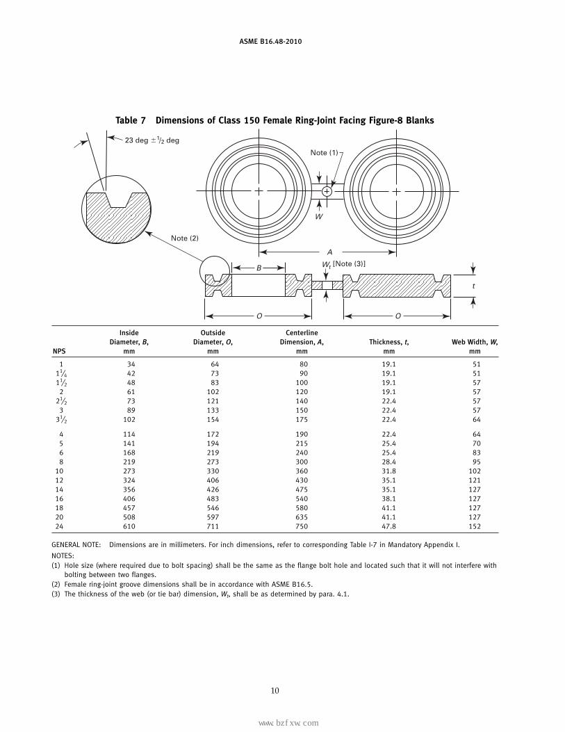
Table 7 Dimensions of Class 150 Female Ring-Joint Facing Figure-8 Blanks
Note (1)
A
B
O
t
Note (2)
O
23 deg �1/2 deg
t
W
W [Note (3)]
Inside Outside CenterlineDiameter, B, Diameter, O, Dimension, A, Thickness, t, Web Width, W,
NPS mm mm mm mm mm
1 34 64 80 19.1 5111⁄4 42 73 90 19.1 5111⁄2 48 83 100 19.1 57
2 61 102 120 19.1 5721⁄2 73 121 140 22.4 57
3 89 133 150 22.4 5731⁄2 102 154 175 22.4 64
4 114 172 190 22.4 645 141 194 215 25.4 706 168 219 240 25.4 838 219 273 300 28.4 95
10 273 330 360 31.8 10212 324 406 430 35.1 12114 356 426 475 35.1 12716 406 483 540 38.1 12718 457 546 580 41.1 12720 508 597 635 41.1 12724 610 711 750 47.8 152
GENERAL NOTE: Dimensions are in millimeters. For inch dimensions, refer to corresponding Table I-7 in Mandatory Appendix I.
NOTES:(1) Hole size (where required due to bolt spacing) shall be the same as the flange bolt hole and located such that it will not interfere with
bolting between two flanges.(2) Female ring-joint groove dimensions shall be in accordance with ASME B16.5.(3) The thickness of the web (or tie bar) dimension, Wt, shall be as determined by para. 4.1.
10
标准分享网 www.bzfxw.com 免费下载
www.bzfxw.com
ASME B16.48-2010
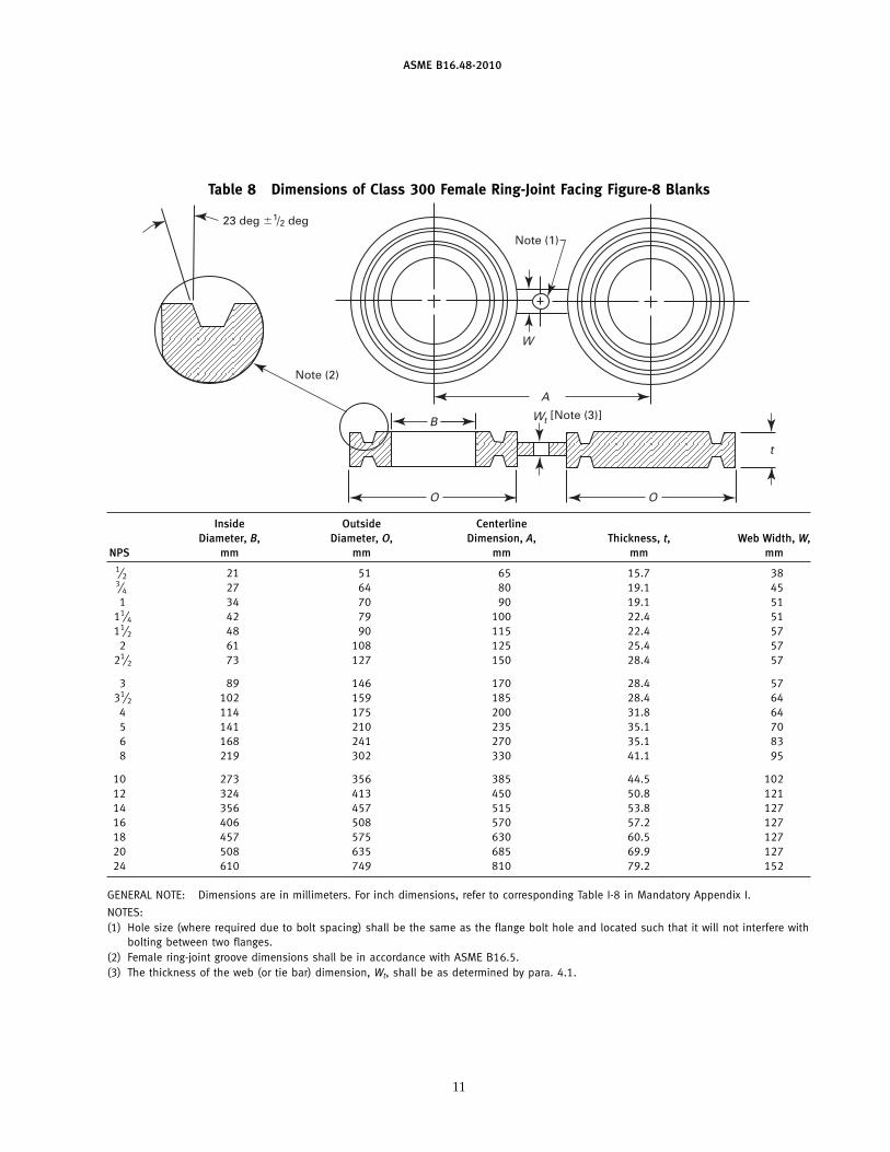
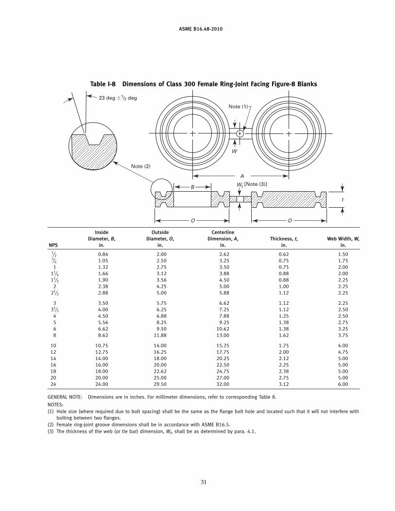
Table 8 Dimensions of Class 300 Female Ring-Joint Facing Figure-8 Blanks
Note (1)
A
B
O
t
Note (2)
O
23 deg �1/2 deg
t
W
W [Note (3)]
Inside Outside CenterlineDiameter, B, Diameter, O, Dimension, A, Thickness, t, Web Width, W,
NPS mm mm mm mm mm1⁄2 21 51 65 15.7 383⁄4 27 64 80 19.1 451 34 70 90 19.1 51
11⁄4 42 79 100 22.4 5111⁄2 48 90 115 22.4 57
2 61 108 125 25.4 5721⁄2 73 127 150 28.4 57
3 89 146 170 28.4 5731⁄2 102 159 185 28.4 64
4 114 175 200 31.8 645 141 210 235 35.1 706 168 241 270 35.1 838 219 302 330 41.1 95
10 273 356 385 44.5 10212 324 413 450 50.8 12114 356 457 515 53.8 12716 406 508 570 57.2 12718 457 575 630 60.5 12720 508 635 685 69.9 12724 610 749 810 79.2 152
GENERAL NOTE: Dimensions are in millimeters. For inch dimensions, refer to corresponding Table I-8 in Mandatory Appendix I.
NOTES:(1) Hole size (where required due to bolt spacing) shall be the same as the flange bolt hole and located such that it will not interfere with
bolting between two flanges.(2) Female ring-joint groove dimensions shall be in accordance with ASME B16.5.(3) The thickness of the web (or tie bar) dimension, Wt, shall be as determined by para. 4.1.
11
www.bzfxw.com
ASME B16.48-2010
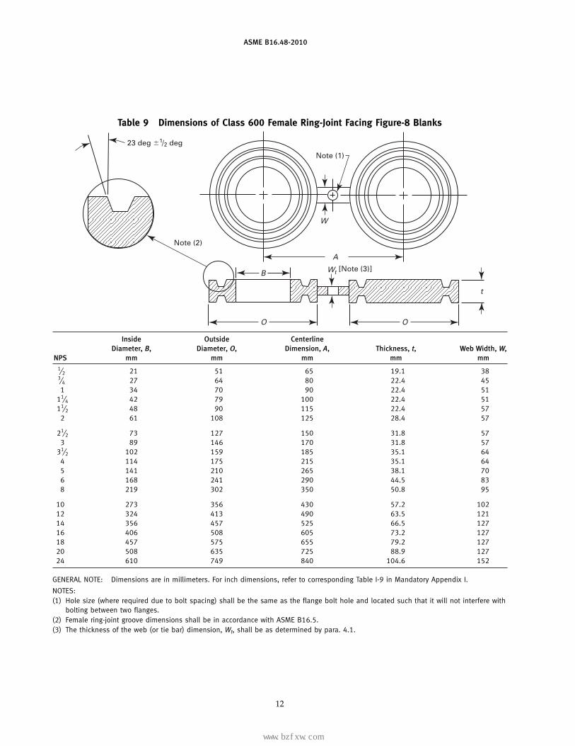
Table 9 Dimensions of Class 600 Female Ring-Joint Facing Figure-8 Blanks
Note (1)
A
B
O
t
Note (2)
O
23 deg �1/2 deg
t
W
W [Note (3)]
Inside Outside CenterlineDiameter, B, Diameter, O, Dimension, A, Thickness, t, Web Width, W,
NPS mm mm mm mm mm1⁄2 21 51 65 19.1 383⁄4 27 64 80 22.4 451 34 70 90 22.4 51
11⁄4 42 79 100 22.4 5111⁄2 48 90 115 22.4 57
2 61 108 125 28.4 57
21⁄2 73 127 150 31.8 573 89 146 170 31.8 57
31⁄2 102 159 185 35.1 644 114 175 215 35.1 645 141 210 265 38.1 706 168 241 290 44.5 838 219 302 350 50.8 95
10 273 356 430 57.2 10212 324 413 490 63.5 12114 356 457 525 66.5 12716 406 508 605 73.2 12718 457 575 655 79.2 12720 508 635 725 88.9 12724 610 749 840 104.6 152
GENERAL NOTE: Dimensions are in millimeters. For inch dimensions, refer to corresponding Table I-9 in Mandatory Appendix I.
NOTES:(1) Hole size (where required due to bolt spacing) shall be the same as the flange bolt hole and located such that it will not interfere with
bolting between two flanges.(2) Female ring-joint groove dimensions shall be in accordance with ASME B16.5.(3) The thickness of the web (or tie bar) dimension, Wt, shall be as determined by para. 4.1.
12
标准分享网 www.bzfxw.com 免费下载
www.bzfxw.com
ASME B16.48-2010
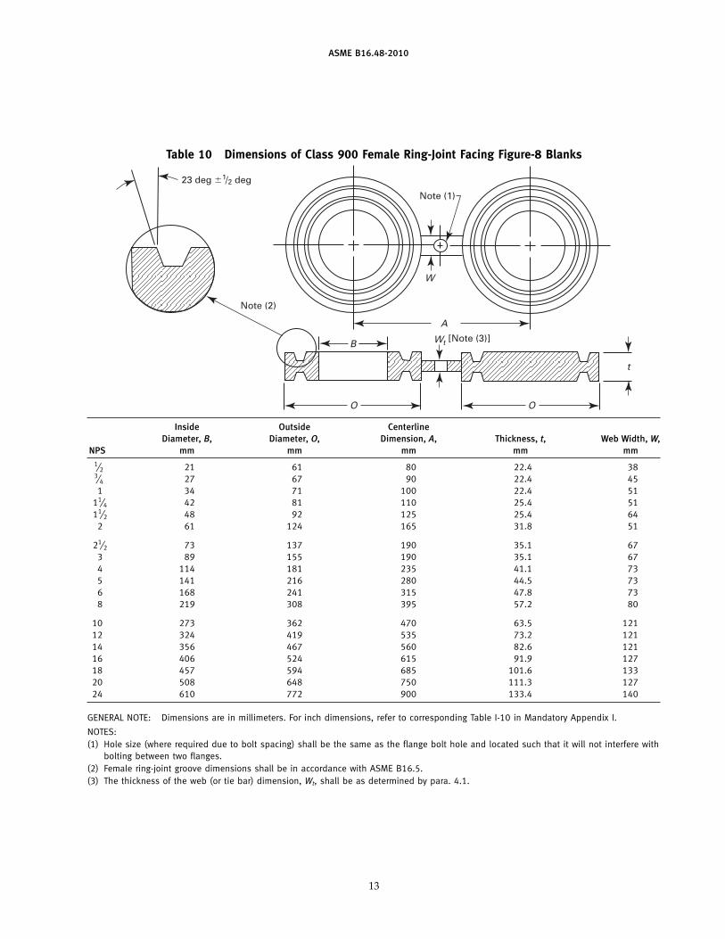
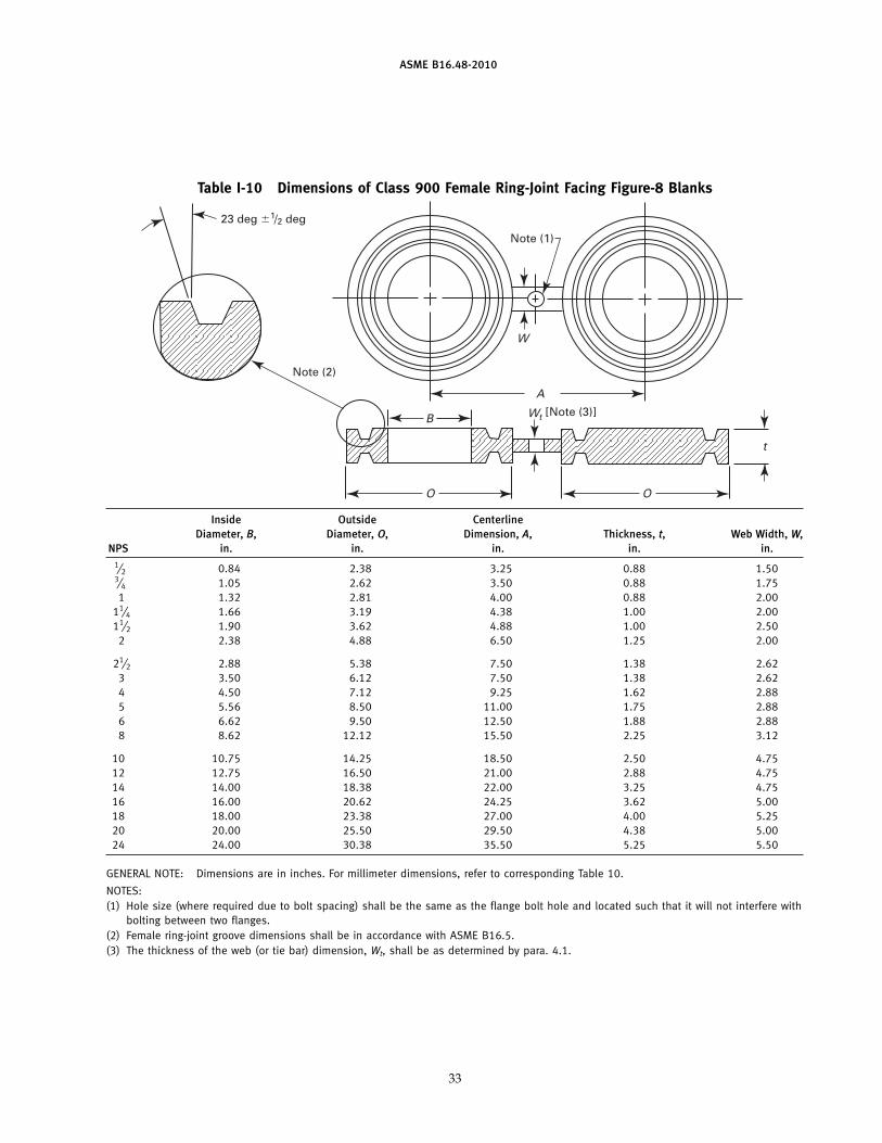
Table 10 Dimensions of Class 900 Female Ring-Joint Facing Figure-8 Blanks
Note (1)
A
B
O
t
Note (2)
O
23 deg �1/2 deg
t
W
W [Note (3)]
Inside Outside CenterlineDiameter, B, Diameter, O, Dimension, A, Thickness, t, Web Width, W,
NPS mm mm mm mm mm1⁄2 21 61 80 22.4 383⁄4 27 67 90 22.4 451 34 71 100 22.4 51
11⁄4 42 81 110 25.4 5111⁄2 48 92 125 25.4 64
2 61 124 165 31.8 51
21⁄2 73 137 190 35.1 673 89 155 190 35.1 674 114 181 235 41.1 735 141 216 280 44.5 736 168 241 315 47.8 738 219 308 395 57.2 80
10 273 362 470 63.5 12112 324 419 535 73.2 12114 356 467 560 82.6 12116 406 524 615 91.9 12718 457 594 685 101.6 13320 508 648 750 111.3 12724 610 772 900 133.4 140
GENERAL NOTE: Dimensions are in millimeters. For inch dimensions, refer to corresponding Table I-10 in Mandatory Appendix I.
NOTES:(1) Hole size (where required due to bolt spacing) shall be the same as the flange bolt hole and located such that it will not interfere with
bolting between two flanges.(2) Female ring-joint groove dimensions shall be in accordance with ASME B16.5.(3) The thickness of the web (or tie bar) dimension, Wt, shall be as determined by para. 4.1.
13
www.bzfxw.com
ASME B16.48-2010
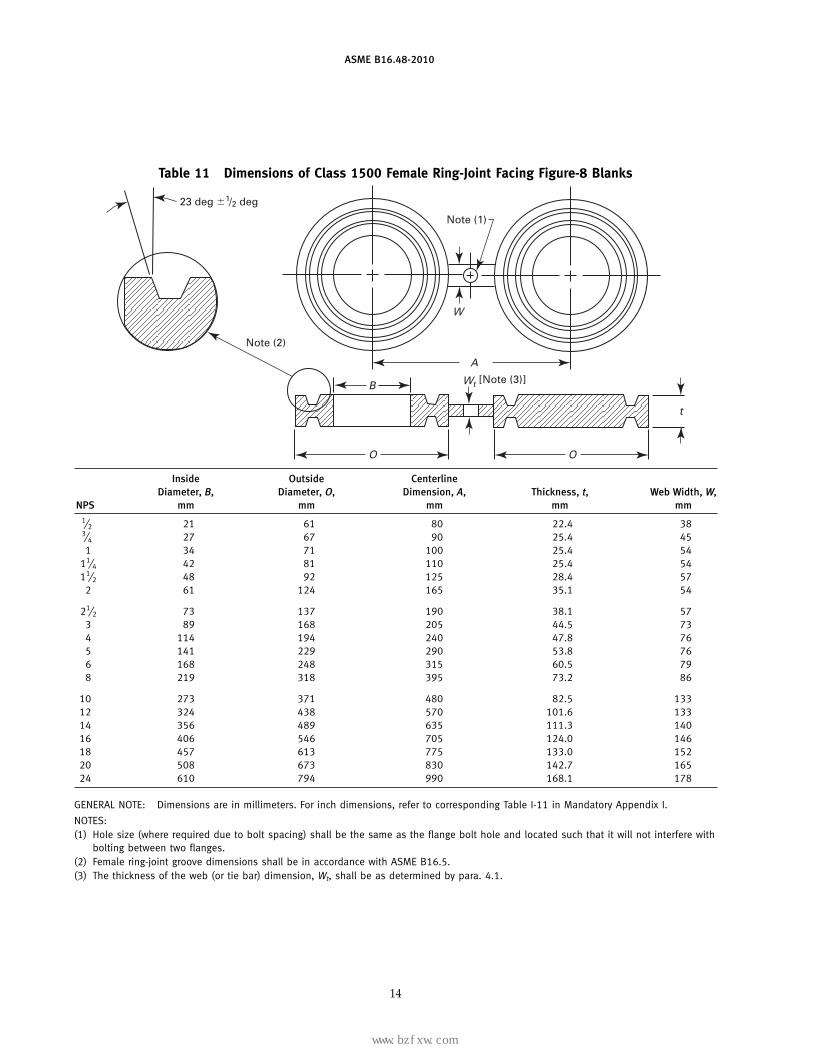
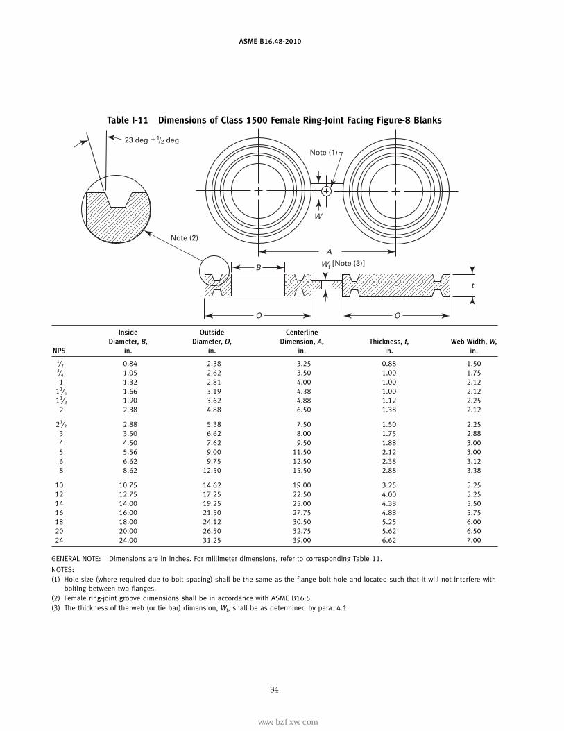
Table 11 Dimensions of Class 1500 Female Ring-Joint Facing Figure-8 Blanks
Note (1)
A
B
O
t
Note (2)
O
23 deg �1/2 deg
t
W
W [Note (3)]
Inside Outside CenterlineDiameter, B, Diameter, O, Dimension, A, Thickness, t, Web Width, W,
NPS mm mm mm mm mm1⁄2 21 61 80 22.4 383⁄4 27 67 90 25.4 451 34 71 100 25.4 54
11⁄4 42 81 110 25.4 5411⁄2 48 92 125 28.4 57
2 61 124 165 35.1 54
21⁄2 73 137 190 38.1 573 89 168 205 44.5 734 114 194 240 47.8 765 141 229 290 53.8 766 168 248 315 60.5 798 219 318 395 73.2 86
10 273 371 480 82.5 13312 324 438 570 101.6 13314 356 489 635 111.3 14016 406 546 705 124.0 14618 457 613 775 133.0 15220 508 673 830 142.7 16524 610 794 990 168.1 178
GENERAL NOTE: Dimensions are in millimeters. For inch dimensions, refer to corresponding Table I-11 in Mandatory Appendix I.
NOTES:(1) Hole size (where required due to bolt spacing) shall be the same as the flange bolt hole and located such that it will not interfere with
bolting between two flanges.(2) Female ring-joint groove dimensions shall be in accordance with ASME B16.5.(3) The thickness of the web (or tie bar) dimension, Wt, shall be as determined by para. 4.1.
14
标准分享网 www.bzfxw.com 免费下载
www.bzfxw.com
ASME B16.48-2010
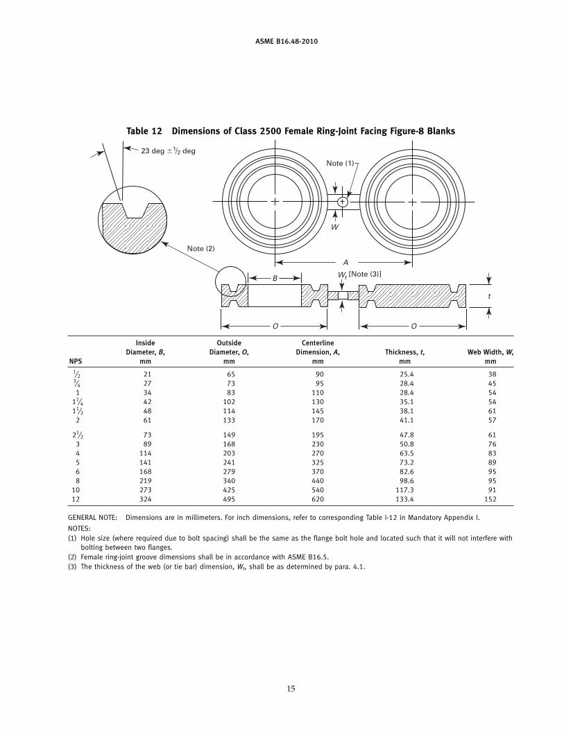
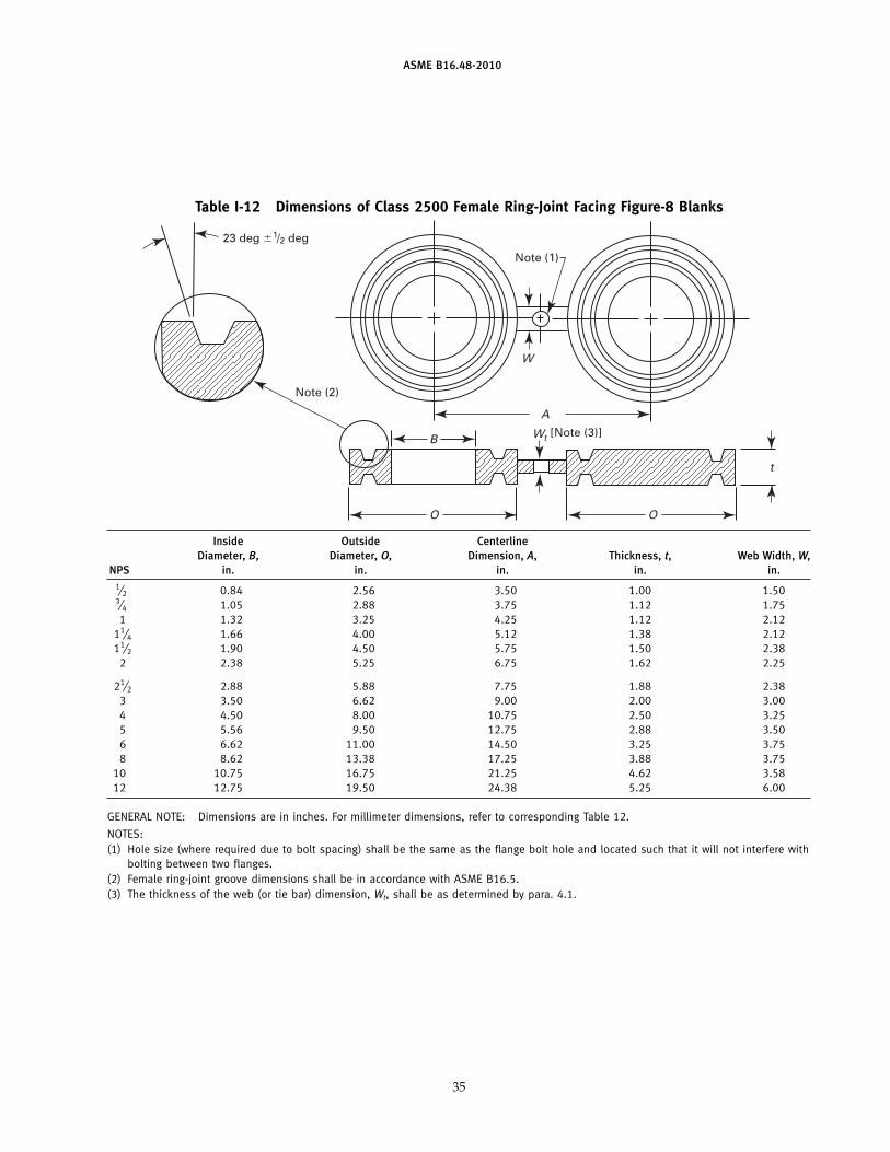
Table 12 Dimensions of Class 2500 Female Ring-Joint Facing Figure-8 Blanks
Note (1)
A
B
O
t
Note (2)
O
23 deg �1/2 deg
t
W
W [Note (3)]
Inside Outside CenterlineDiameter, B, Diameter, O, Dimension, A, Thickness, t, Web Width, W,
NPS mm mm mm mm mm1⁄2 21 65 90 25.4 383⁄4 27 73 95 28.4 451 34 83 110 28.4 54
11⁄4 42 102 130 35.1 5411⁄2 48 114 145 38.1 61
2 61 133 170 41.1 57
21⁄2 73 149 195 47.8 613 89 168 230 50.8 764 114 203 270 63.5 835 141 241 325 73.2 896 168 279 370 82.6 958 219 340 440 98.6 95
10 273 425 540 117.3 9112 324 495 620 133.4 152
GENERAL NOTE: Dimensions are in millimeters. For inch dimensions, refer to corresponding Table I-12 in Mandatory Appendix I.
NOTES:(1) Hole size (where required due to bolt spacing) shall be the same as the flange bolt hole and located such that it will not interfere with
bolting between two flanges.(2) Female ring-joint groove dimensions shall be in accordance with ASME B16.5.(3) The thickness of the web (or tie bar) dimension, Wt, shall be as determined by para. 4.1.
15
www.bzfxw.com
ASME B16.48-2010
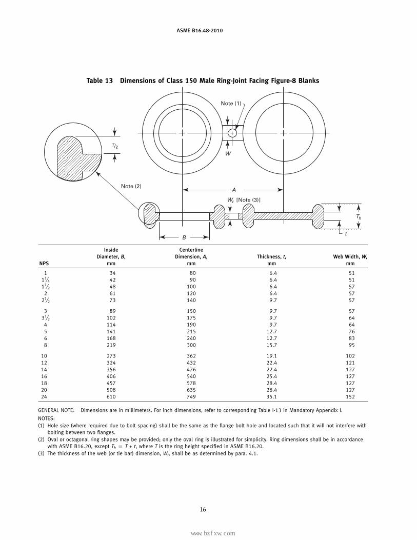
Table 13 Dimensions of Class 150 Male Ring-Joint Facing Figure-8 Blanks
Note (1)
A
W
[Note (3)]
Note (2)
t
Th
Wt
B
T/2
Inside CenterlineDiameter, B, Dimension, A, Thickness, t, Web Width, W,
NPS mm mm mm mm
1 34 80 6.4 5111⁄4 42 90 6.4 5111⁄2 48 100 6.4 57
2 61 120 6.4 5721⁄2 73 140 9.7 57
3 89 150 9.7 5731⁄2 102 175 9.7 64
4 114 190 9.7 645 141 215 12.7 766 168 240 12.7 838 219 300 15.7 95
10 273 362 19.1 10212 324 432 22.4 12114 356 476 22.4 12716 406 540 25.4 12718 457 578 28.4 12720 508 635 28.4 12724 610 749 35.1 152
GENERAL NOTE: Dimensions are in millimeters. For inch dimensions, refer to corresponding Table I-13 in Mandatory Appendix I.
NOTES:(1) Hole size (where required due to bolt spacing) shall be the same as the flange bolt hole and located such that it will not interfere with
bolting between two flanges.(2) Oval or octagonal ring shapes may be provided; only the oval ring is illustrated for simplicity. Ring dimensions shall be in accordance
with ASME B16.20, except Th p T + t, where T is the ring height specified in ASME B16.20.(3) The thickness of the web (or tie bar) dimension, Wt, shall be as determined by para. 4.1.
16
标准分享网 www.bzfxw.com 免费下载
www.bzfxw.com
ASME B16.48-2010
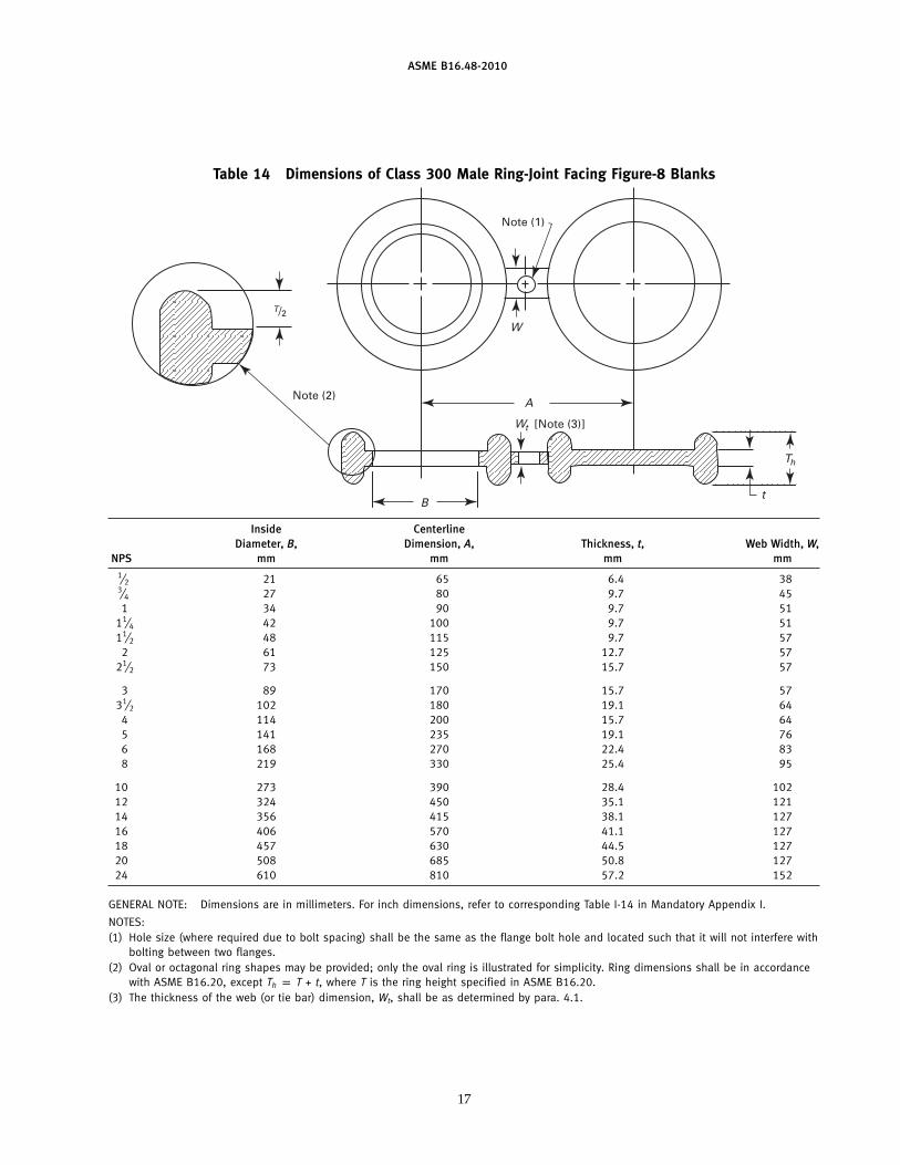
Table 14 Dimensions of Class 300 Male Ring-Joint Facing Figure-8 Blanks
Note (1)
A
W
[Note (3)]
Note (2)
t
Th
Wt
B
T/2
Inside CenterlineDiameter, B, Dimension, A, Thickness, t, Web Width, W,
NPS mm mm mm mm1⁄2 21 65 6.4 383⁄4 27 80 9.7 451 34 90 9.7 51
11⁄4 42 100 9.7 5111⁄2 48 115 9.7 57
2 61 125 12.7 5721⁄2 73 150 15.7 57
3 89 170 15.7 5731⁄2 102 180 19.1 64
4 114 200 15.7 645 141 235 19.1 766 168 270 22.4 838 219 330 25.4 95
10 273 390 28.4 10212 324 450 35.1 12114 356 415 38.1 12716 406 570 41.1 12718 457 630 44.5 12720 508 685 50.8 12724 610 810 57.2 152
GENERAL NOTE: Dimensions are in millimeters. For inch dimensions, refer to corresponding Table I-14 in Mandatory Appendix I.
NOTES:(1) Hole size (where required due to bolt spacing) shall be the same as the flange bolt hole and located such that it will not interfere with
bolting between two flanges.(2) Oval or octagonal ring shapes may be provided; only the oval ring is illustrated for simplicity. Ring dimensions shall be in accordance
with ASME B16.20, except Th p T + t, where T is the ring height specified in ASME B16.20.(3) The thickness of the web (or tie bar) dimension, Wt, shall be as determined by para. 4.1.
17
www.bzfxw.com
ASME B16.48-2010
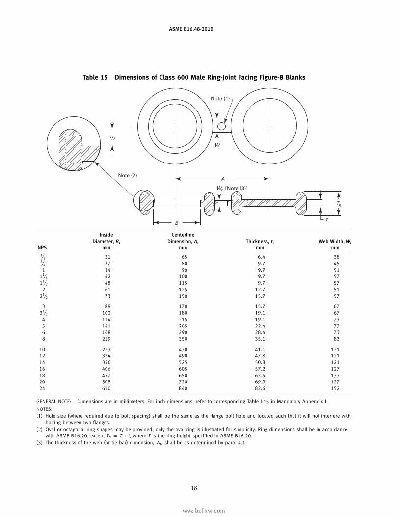
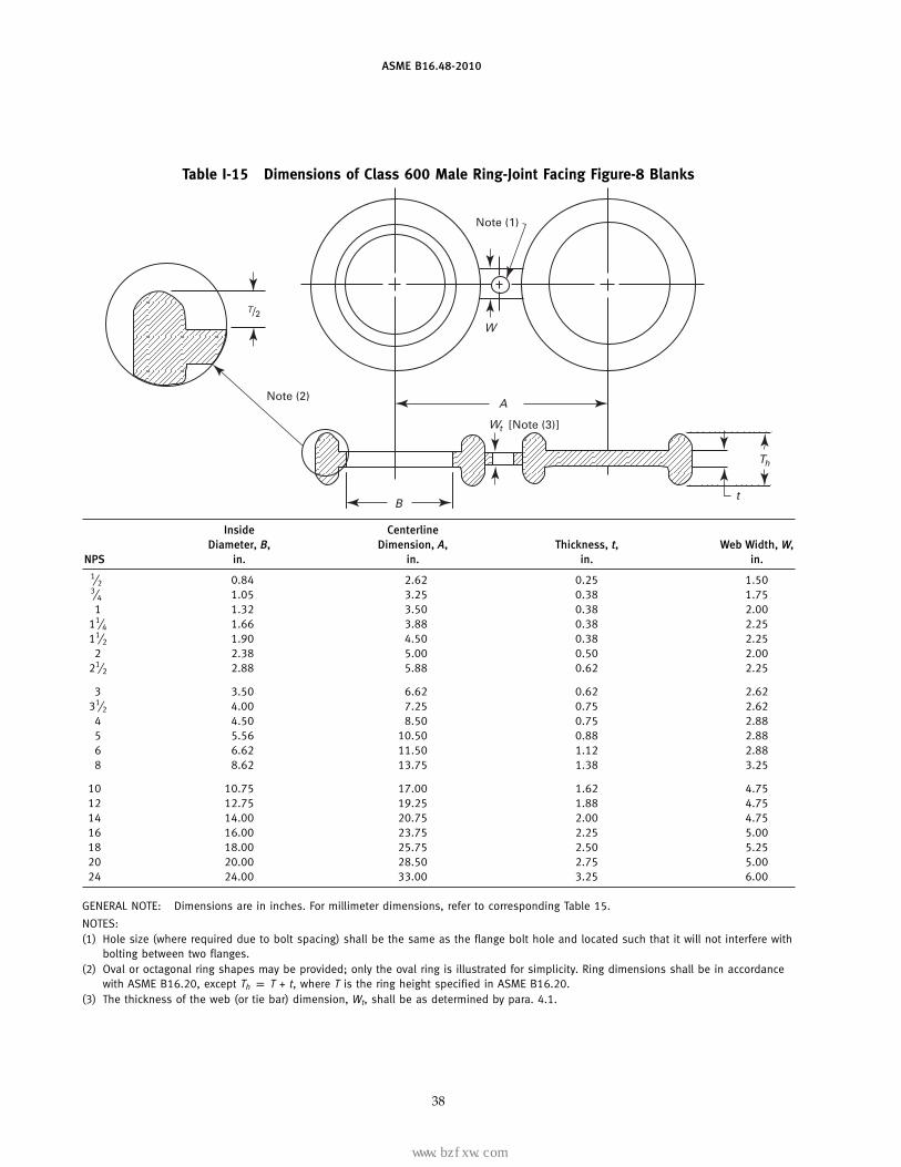
Table 15 Dimensions of Class 600 Male Ring-Joint Facing Figure-8 Blanks
Note (1)
A
W
[Note (3)]
Note (2)
t
Th
Wt
B
T/2
Inside CenterlineDiameter, B, Dimension, A, Thickness, t, Web Width, W,
NPS mm mm mm mm1⁄2 21 65 6.4 383⁄4 27 80 9.7 451 34 90 9.7 51
11⁄4 42 100 9.7 5711⁄2 48 115 9.7 57
2 61 125 12.7 5121⁄2 73 150 15.7 57
3 89 170 15.7 6731⁄2 102 180 19.1 67
4 114 215 19.1 735 141 265 22.4 736 168 290 28.4 738 219 350 35.1 83
10 273 430 41.1 12112 324 490 47.8 12114 356 525 50.8 12116 406 605 57.2 12718 457 650 63.5 13320 508 720 69.9 12724 610 840 82.6 152
GENERAL NOTE: Dimensions are in millimeters. For inch dimensions, refer to corresponding Table I-15 in Mandatory Appendix I.
NOTES:(1) Hole size (where required due to bolt spacing) shall be the same as the flange bolt hole and located such that it will not interfere with
bolting between two flanges.(2) Oval or octagonal ring shapes may be provided; only the oval ring is illustrated for simplicity. Ring dimensions shall be in accordance
with ASME B16.20, except Th p T + t, where T is the ring height specified in ASME B16.20.(3) The thickness of the web (or tie bar) dimension, Wt, shall be as determined by para. 4.1.
18
标准分享网 www.bzfxw.com 免费下载
www.bzfxw.com
ASME B16.48-2010
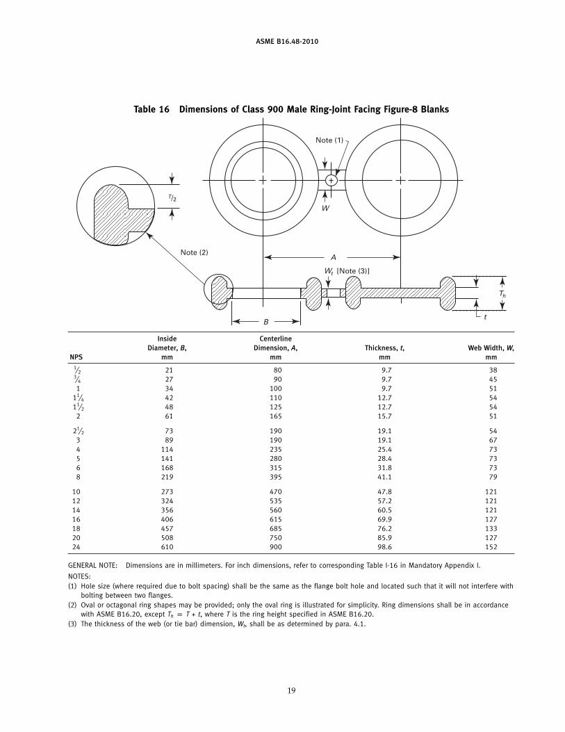
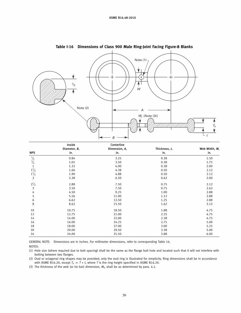
Table 16 Dimensions of Class 900 Male Ring-Joint Facing Figure-8 Blanks
Note (1)
A
W
[Note (3)]
Note (2)
t
Th
Wt
B
T/2
Inside CenterlineDiameter, B, Dimension, A, Thickness, t, Web Width, W,
NPS mm mm mm mm1⁄2 21 80 9.7 383⁄4 27 90 9.7 451 34 100 9.7 51
11⁄4 42 110 12.7 5411⁄2 48 125 12.7 54
2 61 165 15.7 51
21⁄2 73 190 19.1 543 89 190 19.1 674 114 235 25.4 735 141 280 28.4 736 168 315 31.8 738 219 395 41.1 79
10 273 470 47.8 12112 324 535 57.2 12114 356 560 60.5 12116 406 615 69.9 12718 457 685 76.2 13320 508 750 85.9 12724 610 900 98.6 152
GENERAL NOTE: Dimensions are in millimeters. For inch dimensions, refer to corresponding Table I-16 in Mandatory Appendix I.
NOTES:(1) Hole size (where required due to bolt spacing) shall be the same as the flange bolt hole and located such that it will not interfere with
bolting between two flanges.(2) Oval or octagonal ring shapes may be provided; only the oval ring is illustrated for simplicity. Ring dimensions shall be in accordance
with ASME B16.20, except Th p T + t, where T is the ring height specified in ASME B16.20.(3) The thickness of the web (or tie bar) dimension, Wt, shall be as determined by para. 4.1.
19
www.bzfxw.com
ASME B16.48-2010
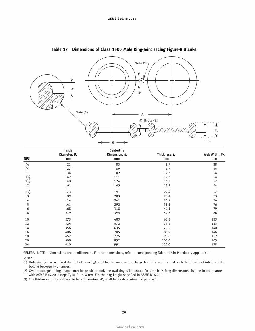
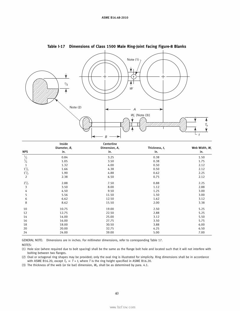
Table 17 Dimensions of Class 1500 Male Ring-Joint Facing Figure-8 Blanks
Note (1)
A
W
[Note (3)]
Note (2)
t
Th
Wt
B
T/2
Inside CenterlineDiameter, B, Dimension, A, Thickness, t, Web Width, W,
NPS mm mm mm mm1⁄2 21 83 9.7 383⁄4 27 89 9.7 451 34 102 12.7 54
11⁄4 42 111 12.7 5411⁄2 48 124 15.7 57
2 61 165 19.1 54
21⁄2 73 191 22.4 573 89 203 28.4 734 114 241 31.8 765 141 292 38.1 766 168 318 41.1 798 219 394 50.8 86
10 273 483 63.5 13312 324 572 73.2 13314 356 635 79.2 14016 406 705 88.9 14618 457 775 98.6 15220 508 832 108.0 16524 610 991 127.0 178
GENERAL NOTE: Dimensions are in millimeters. For inch dimensions, refer to corresponding Table I-17 in Mandatory Appendix I.
NOTES:(1) Hole size (where required due to bolt spacing) shall be the same as the flange bolt hole and located such that it will not interfere with
bolting between two flanges.(2) Oval or octagonal ring shapes may be provided; only the oval ring is illustrated for simplicity. Ring dimensions shall be in accordance
with ASME B16.20, except Th p T + t, where T is the ring height specified in ASME B16.20.(3) The thickness of the web (or tie bar) dimension, Wt, shall be as determined by para. 4.1.
20
标准分享网 www.bzfxw.com 免费下载
www.bzfxw.com
ASME B16.48-2010
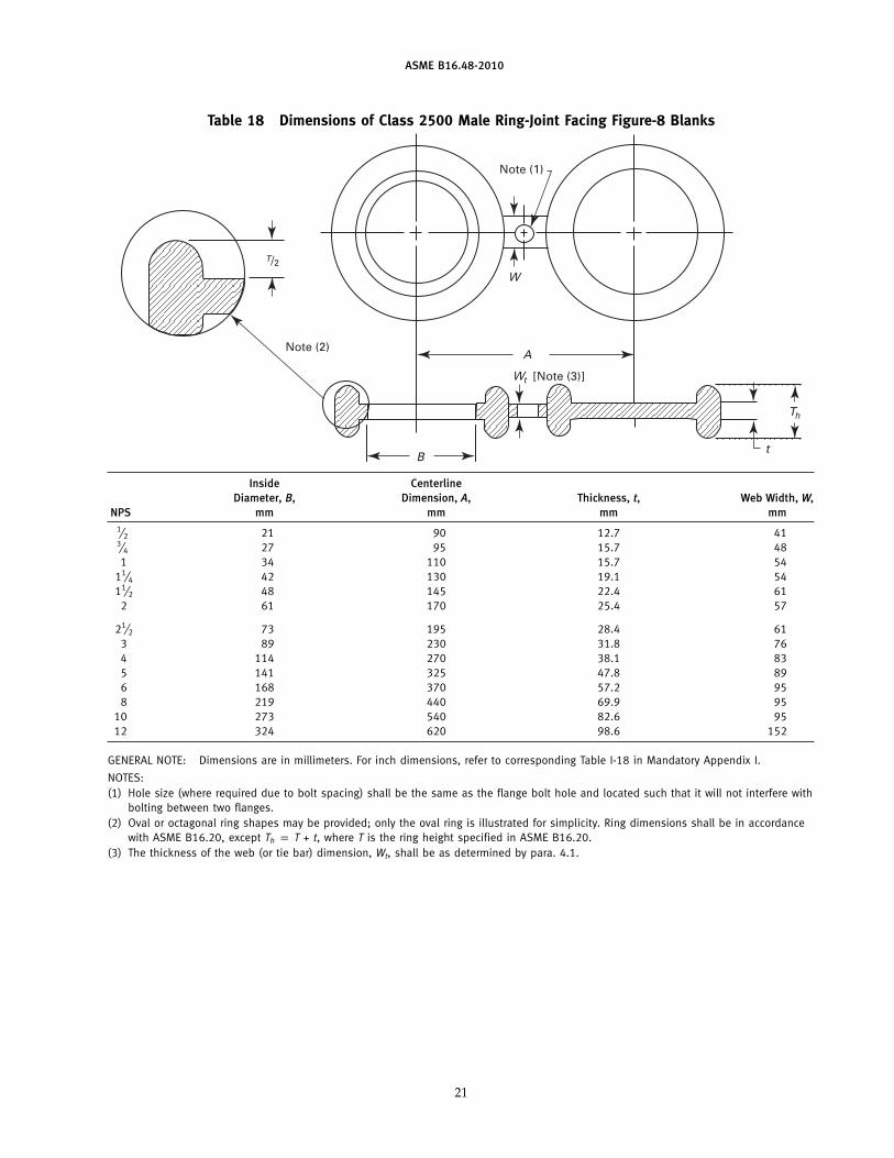
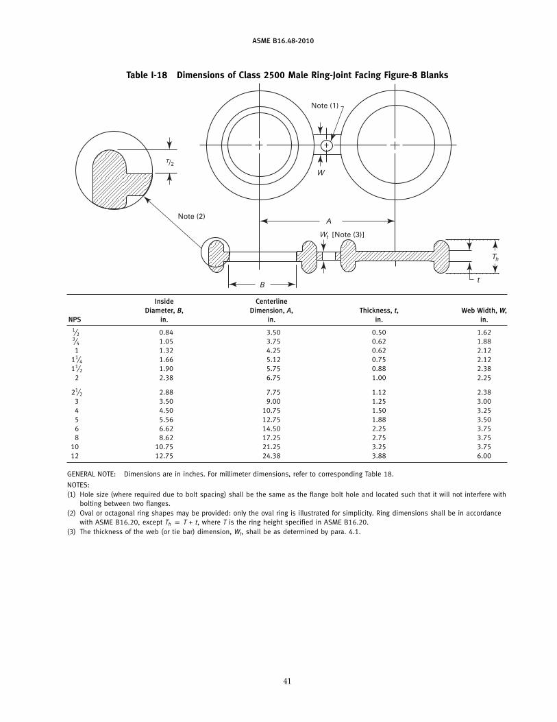
Table 18 Dimensions of Class 2500 Male Ring-Joint Facing Figure-8 Blanks
Note (1)
A
W
[Note (3)]
Note (2)
t
Th
Wt
B
T/2
Inside CenterlineDiameter, B, Dimension, A, Thickness, t, Web Width, W,
NPS mm mm mm mm1⁄2 21 90 12.7 413⁄4 27 95 15.7 481 34 110 15.7 54
11⁄4 42 130 19.1 5411⁄2 48 145 22.4 61
2 61 170 25.4 57
21⁄2 73 195 28.4 613 89 230 31.8 764 114 270 38.1 835 141 325 47.8 896 168 370 57.2 958 219 440 69.9 95
10 273 540 82.6 9512 324 620 98.6 152
GENERAL NOTE: Dimensions are in millimeters. For inch dimensions, refer to corresponding Table I-18 in Mandatory Appendix I.
NOTES:(1) Hole size (where required due to bolt spacing) shall be the same as the flange bolt hole and located such that it will not interfere with
bolting between two flanges.(2) Oval or octagonal ring shapes may be provided; only the oval ring is illustrated for simplicity. Ring dimensions shall be in accordance
with ASME B16.20, except Th p T + t, where T is the ring height specified in ASME B16.20.(3) The thickness of the web (or tie bar) dimension, Wt, shall be as determined by para. 4.1.
21

www.bzfxw.comINTENTIONALLY LEFT BLANK
22
标准分享网 www.bzfxw.com 免费下载
www.bzfxw.com
ASME B16.48-2010
MANDATORY APPENDIX IDIMENSIONAL DATA FOR LINE BLANKS IN
U.S. CUSTOMARY UNITS
The tables and figures included in this MandatoryAppendix provide dimensional data in U.S. Customaryunits for the following: Class 150, 300, 600, 900, 1500,and 2500 blanks.
23
(10)
www.bzfxw.com
ASME B16.48-2010
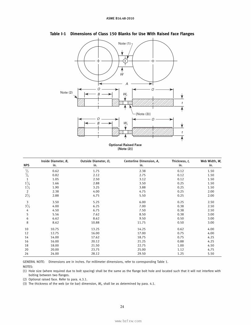
Table I-1 Dimensions of Class 150 Blanks for Use With Raised Face Flanges
Note (1)
A
O
BO
t
Note (2)
[Note (3)]
t
W
W
OB
O
t
Optional Raised Face
[Note (2)]
tW
Inside Diameter, B, Outside Diameter, O, Centerline Dimension, A, Thickness, t, Web Width, W,NPS in. in. in. in. in.
1⁄2 0.62 1.75 2.38 0.12 1.503⁄4 0.82 2.12 2.75 0.12 1.501 1.05 2.50 3.12 0.12 1.50
11⁄4 1.66 2.88 3.50 0.25 1.5011⁄2 1.90 3.25 3.88 0.25 1.50
2 2.38 4.00 4.75 0.25 2.0021⁄2 2.88 4.75 5.50 0.25 2.00
3 3.50 5.25 6.00 0.25 2.5031⁄2 4.00 6.25 7.00 0.38 2.50
4 4.50 6.75 7.50 0.38 2.505 5.56 7.62 8.50 0.38 3.006 6.62 8.62 9.50 0.50 3.008 8.62 10.88 11.75 0.50 3.00
10 10.75 13.25 14.25 0.62 4.0012 12.75 16.00 17.00 0.75 4.0014 14.00 17.62 18.75 0.75 4.2516 16.00 20.12 21.25 0.88 4.2518 18.00 21.50 22.75 1.00 4.5020 20.00 23.75 25.00 1.12 4.7524 24.00 28.12 29.50 1.25 5.50
GENERAL NOTE: Dimensions are in inches. For millimeter dimensions, refer to corresponding Table 1.
NOTES:(1) Hole size (where required due to bolt spacing) shall be the same as the flange bolt hole and located such that it will not interfere with
bolting between two flanges.(2) Optional raised face. Refer to para. 4.3.1.(3) The thickness of the web (or tie bar) dimension, Wt, shall be as determined by para. 4.1.
24
标准分享网 www.bzfxw.com 免费下载
www.bzfxw.com
ASME B16.48-2010
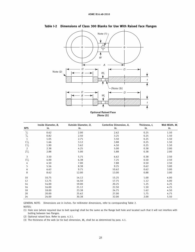
Table I-2 Dimensions of Class 300 Blanks for Use With Raised Face Flanges
Note (1)
A
O
BO
t
Note (2)
[Note (3)]
t
W
W
OB
O
t
Optional Raised Face
[Note (2)]
tW
Inside Diameter, B, Outside Diameter, O, Centerline Dimension, A, Thickness, t, Web Width, W,NPS in. in. in. in. in.
1⁄2 0.62 2.00 2.62 0.25 1.503⁄4 0.82 2.50 3.25 0.25 1.501 1.05 2.75 3.50 0.25 1.50
11⁄4 1.66 3.12 3.88 0.25 1.5011⁄2 1.90 3.62 4.50 0.25 1.50
2 2.38 4.25 5.00 0.38 2.0021⁄2 2.88 5.00 5.88 0.38 2.00
3 3.50 5.75 6.62 0.38 2.5031⁄2 4.00 6.38 7.25 0.50 2.50
4 4.50 7.00 7.88 0.50 2.505 5.56 8.38 9.25 0.62 3.006 6.62 9.75 10.62 0.62 3.008 8.62 12.00 13.00 0.88 3.00
10 10.75 14.12 15.25 1.00 4.0012 12.75 16.50 17.75 1.12 4.0014 14.00 19.00 20.25 1.25 4.2516 16.00 21.12 22.50 1.50 4.2518 18.00 23.38 24.75 1.62 4.5020 20.00 25.62 27.00 1.75 4.7524 24.00 30.38 32.00 2.00 5.50
GENERAL NOTE: Dimensions are in inches. For millimeter dimensions, refer to corresponding Table 2.
NOTES:(1) Hole size (where required due to bolt spacing) shall be the same as the flange bolt hole and located such that it will not interfere with
bolting between two flanges.(2) Optional raised face. Refer to para. 4.3.1.(3) The thickness of the web (or tie bar) dimension, Wt, shall be as determined by para. 4.1.
25
www.bzfxw.com
ASME B16.48-2010
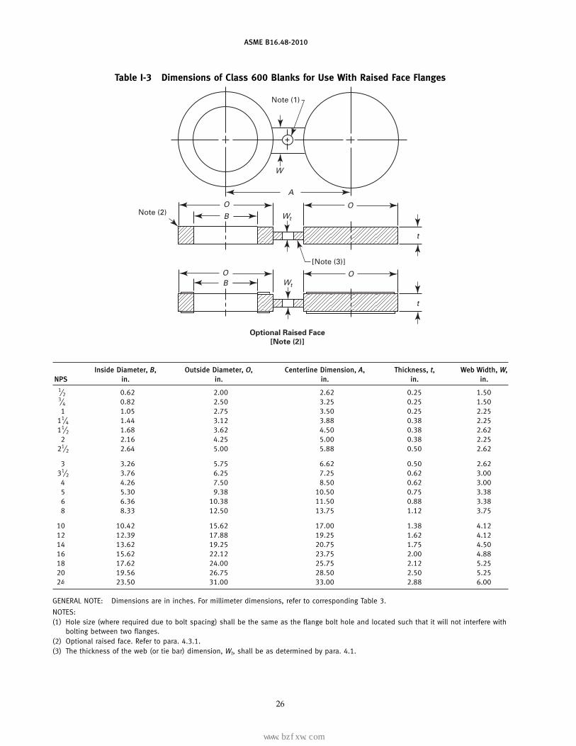
Table I-3 Dimensions of Class 600 Blanks for Use With Raised Face Flanges
Note (1)
A
O
BO
t
Note (2)
[Note (3)]
t
W
W
OB
O
t
Optional Raised Face
[Note (2)]
tW
Inside Diameter, B, Outside Diameter, O, Centerline Dimension, A, Thickness, t, Web Width, W,NPS in. in. in. in. in.
1⁄2 0.62 2.00 2.62 0.25 1.503⁄4 0.82 2.50 3.25 0.25 1.501 1.05 2.75 3.50 0.25 2.25
11⁄4 1.44 3.12 3.88 0.38 2.2511⁄2 1.68 3.62 4.50 0.38 2.62
2 2.16 4.25 5.00 0.38 2.2521⁄2 2.64 5.00 5.88 0.50 2.62
3 3.26 5.75 6.62 0.50 2.6231⁄2 3.76 6.25 7.25 0.62 3.00
4 4.26 7.50 8.50 0.62 3.005 5.30 9.38 10.50 0.75 3.386 6.36 10.38 11.50 0.88 3.388 8.33 12.50 13.75 1.12 3.75
10 10.42 15.62 17.00 1.38 4.1212 12.39 17.88 19.25 1.62 4.1214 13.62 19.25 20.75 1.75 4.5016 15.62 22.12 23.75 2.00 4.8818 17.62 24.00 25.75 2.12 5.2520 19.56 26.75 28.50 2.50 5.2524 23.50 31.00 33.00 2.88 6.00
GENERAL NOTE: Dimensions are in inches. For millimeter dimensions, refer to corresponding Table 3.
NOTES:(1) Hole size (where required due to bolt spacing) shall be the same as the flange bolt hole and located such that it will not interfere with
bolting between two flanges.(2) Optional raised face. Refer to para. 4.3.1.(3) The thickness of the web (or tie bar) dimension, Wt, shall be as determined by para. 4.1.
26
标准分享网 www.bzfxw.com 免费下载
www.bzfxw.com
ASME B16.48-2010
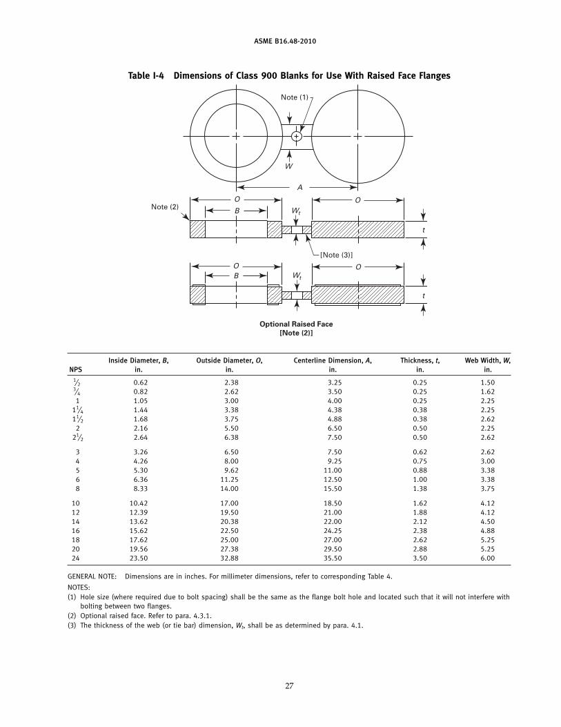
Table I-4 Dimensions of Class 900 Blanks for Use With Raised Face Flanges
Note (1)
A
O
BO
t
Note (2)
[Note (3)]
t
W
W
OB
O
t
Optional Raised Face
[Note (2)]
tW
Inside Diameter, B, Outside Diameter, O, Centerline Dimension, A, Thickness, t, Web Width, W,NPS in. in. in. in. in.
1⁄2 0.62 2.38 3.25 0.25 1.503⁄4 0.82 2.62 3.50 0.25 1.621 1.05 3.00 4.00 0.25 2.25
11⁄4 1.44 3.38 4.38 0.38 2.2511⁄2 1.68 3.75 4.88 0.38 2.62
2 2.16 5.50 6.50 0.50 2.2521⁄2 2.64 6.38 7.50 0.50 2.62
3 3.26 6.50 7.50 0.62 2.624 4.26 8.00 9.25 0.75 3.005 5.30 9.62 11.00 0.88 3.386 6.36 11.25 12.50 1.00 3.388 8.33 14.00 15.50 1.38 3.75
10 10.42 17.00 18.50 1.62 4.1212 12.39 19.50 21.00 1.88 4.1214 13.62 20.38 22.00 2.12 4.5016 15.62 22.50 24.25 2.38 4.8818 17.62 25.00 27.00 2.62 5.2520 19.56 27.38 29.50 2.88 5.2524 23.50 32.88 35.50 3.50 6.00
GENERAL NOTE: Dimensions are in inches. For millimeter dimensions, refer to corresponding Table 4.
NOTES:(1) Hole size (where required due to bolt spacing) shall be the same as the flange bolt hole and located such that it will not interfere with
bolting between two flanges.(2) Optional raised face. Refer to para. 4.3.1.(3) The thickness of the web (or tie bar) dimension, Wt, shall be as determined by para. 4.1.
27
www.bzfxw.com
ASME B16.48-2010
Table I-5 Dimensions of Class 1500 Blanks for Use With Raised Face Flanges
Note (1)
A
O
BO
t
Note (2)
[Note (3)]
t
W
W
OB
O
t
Optional Raised Face
[Note (2)]
tW
Inside Diameter, B, Outside Diameter, O, Centerline Dimension, A, Thickness, t, Web Width, W,NPS in. in. in. in. in.
1⁄2 0.62 2.38 3.25 0.25 1.503⁄4 0.82 2.62 3.50 0.38 1.621 1.05 3.00 4.00 0.38 2.20
11⁄4 1.38 3.38 4.38 0.38 2.5011⁄2 1.61 3.75 4.88 0.50 2.75
2 2.07 5.50 6.50 0.50 2.75
21⁄2 2.47 6.38 7.50 0.62 3.003 3.07 6.75 8.00 0.75 3.004 4.03 8.12 9.50 0.88 3.505 5.05 9.88 11.50 1.12 3.506 6.06 11.00 12.50 1.38 3.508 7.98 13.75 15.50 1.62 4.00
10 10.02 17.00 19.00 2.00 4.5012 11.94 20.38 22.50 2.38 4.5014 13.12 22.62 25.00 2.62 5.0016 15.00 25.12 27.75 3.00 5.2518 16.88 27.62 30.50 3.38 5.7520 18.81 29.62 32.75 3.75 6.0024 22.62 35.38 39.00 4.38 7.00
GENERAL NOTE: Dimensions are in inches. For millimeter dimensions, refer to corresponding Table 5.
NOTES:(1) Hole size (where required due to bolt spacing) shall be the same as the flange bolt hole and located such that it will not interfere with
bolting between two flanges.(2) Optional raised face. Refer to para. 4.3.1.(3) The thickness of the web (or tie bar) dimension, Wt, shall be as determined by para. 4.1.
28
标准分享网 www.bzfxw.com 免费下载
www.bzfxw.com
ASME B16.48-2010
Table I-6 Dimensions of Class 2500 Blanks for Use With Raised Face Flanges
Note (1)
A
O
BO
t
Note (2)
[Note (3)]
t
W
W
OB
O
t
Optional Raised Face
[Note (2)]
tW
Inside Diameter, B, Outside Diameter, O, Centerline Dimension, A, Thickness, t, Web Width, W,NPS in. in. in. in. in.
1⁄2 0.62 2.62 3.50 0.38 1.503⁄4 0.82 2.88 3.75 0.38 1.621 1.05 3.25 4.25 0.38 2.50
11⁄4 1.38 4.00 5.12 0.50 2.5011⁄2 1.61 4.50 5.75 0.62 2.75
2 2.07 5.62 6.75 0.62 2.7521⁄2 2.47 6.50 7.75 0.75 3.00
3 3.07 7.62 9.00 0.88 3.004 4.03 9.12 10.75 1.12 3.505 5.05 10.88 12.75 1.38 3.506 6.06 12.38 14.50 1.62 3.508 7.81 15.12 17.25 2.12 4.00
10 9.75 18.62 21.25 2.62 4.5012 11.37 21.50 24.38 3.12 4.50
GENERAL NOTE: Dimensions are in inches. For millimeter dimensions, refer to corresponding Table 6.
NOTES:(1) Hole size (where required due to bolt spacing) shall be the same as the flange bolt hole and located such that it will not interfere with
bolting between two flanges.(2) Optional raised face. Refer to para. 4.3.1.(3) The thickness of the web (or tie bar) dimension, Wt, shall be as determined by para. 4.1.
29

www.bzfxw.com
ASME B16.48-2010
Table I-7 Dimensions of Class 150 Female Ring-Joint Facing Figure-8 Blanks
Note (1)
A
B
O
t
Note (2)
O
23 deg �1/2 deg
t
W
W [Note (3)]
Inside Outside CenterlineDiameter, B, Diameter, O, Dimension, A, Thickness, t, Web Width, W,
NPS in. in. in. in. in.
1 1.32 2.50 3.12 0.75 2.0011⁄4 1.66 2.88 3.50 0.75 2.0011⁄2 1.90 3.25 3.88 0.75 2.25
2 2.38 4.00 4.75 0.75 2.2521⁄2 2.88 4.75 5.50 0.88 2.25
3 3.50 5.25 6.00 0.88 2.2531⁄2 4.00 6.06 7.00 0.88 2.50
4 4.50 6.75 7.50 0.88 2.505 5.56 7.62 8.50 1.00 2.756 6.62 8.62 9.50 1.00 3.258 8.62 10.75 11.75 1.12 3.75
10 10.75 13.00 14.25 1.25 4.0012 12.75 16.00 17.00 1.38 4.7514 14.00 16.75 18.75 1.38 5.0016 16.00 19.00 21.25 1.50 5.0018 18.00 21.50 22.75 1.62 5.0020 20.00 23.50 25.00 1.62 5.0024 24.00 28.00 29.50 1.88 6.00
GENERAL NOTE: Dimensions are in inches. For millimeter dimensions, refer to corresponding Table 7.
NOTES:(1) Hole size (where required due to bolt spacing) shall be the same as the flange bolt hole and located such that it will not interfere with
bolting between two flanges.(2) Female ring-joint groove dimensions shall be in accordance with ASME B16.5.(3) The thickness of the web (or tie bar) dimension, Wt, shall be as determined by para. 4.1.
30
标准分享网 www.bzfxw.com 免费下载
www.bzfxw.com
ASME B16.48-2010
Table I-8 Dimensions of Class 300 Female Ring-Joint Facing Figure-8 Blanks
Note (1)
A
B
O
t
Note (2)
O
23 deg �1/2 deg
t
W
W [Note (3)]
Inside Outside CenterlineDiameter, B, Diameter, O, Dimension, A, Thickness, t, Web Width, W,
NPS in. in. in. in. in.1⁄2 0.84 2.00 2.62 0.62 1.503⁄4 1.05 2.50 3.25 0.75 1.751 1.32 2.75 3.50 0.75 2.00
11⁄4 1.66 3.12 3.88 0.88 2.0011⁄2 1.90 3.56 4.50 0.88 2.25
2 2.38 4.25 5.00 1.00 2.2521⁄2 2.88 5.00 5.88 1.12 2.25
3 3.50 5.75 6.62 1.12 2.2531⁄2 4.00 6.25 7.25 1.12 2.50
4 4.50 6.88 7.88 1.25 2.505 5.56 8.25 9.25 1.38 2.756 6.62 9.50 10.62 1.38 3.258 8.62 11.88 13.00 1.62 3.75
10 10.75 14.00 15.25 1.75 4.0012 12.75 16.25 17.75 2.00 4.7514 14.00 18.00 20.25 2.12 5.0016 16.00 20.00 22.50 2.25 5.0018 18.00 22.62 24.75 2.38 5.0020 20.00 25.00 27.00 2.75 5.0024 24.00 29.50 32.00 3.12 6.00
GENERAL NOTE: Dimensions are in inches. For millimeter dimensions, refer to corresponding Table 8.
NOTES:(1) Hole size (where required due to bolt spacing) shall be the same as the flange bolt hole and located such that it will not interfere with
bolting between two flanges.(2) Female ring-joint groove dimensions shall be in accordance with ASME B16.5.(3) The thickness of the web (or tie bar) dimension, Wt, shall be as determined by para. 4.1.
31

www.bzfxw.com
ASME B16.48-2010
Table I-9 Dimensions of Class 600 Female Ring-Joint Facing Figure-8 Blanks
Note (1)
A
B
O
t
Note (2)
O
23 deg �1/2 deg
t
W
W [Note (3)]
Inside Outside CenterlineDiameter, B, Diameter, O, Dimension, A, Thickness, t, Web Width, W,
NPS in. in. in. in. in.1⁄2 0.84 2.00 2.62 0.75 1.503⁄4 1.05 2.50 3.25 0.88 1.751 1.32 2.75 3.50 0.88 2.00
11⁄4 1.66 3.12 3.88 0.88 2.0011⁄2 1.90 3.56 4.50 0.88 2.25
2 2.38 4.25 5.00 1.12 2.25
21⁄2 2.88 5.00 5.88 1.25 2.253 3.50 5.75 6.62 1.25 2.25
31⁄2 4.00 6.25 7.25 1.38 2.504 4.50 6.88 8.50 1.38 2.505 5.56 8.25 10.50 1.50 2.756 6.62 9.50 11.50 1.75 3.258 8.62 11.88 13.75 2.00 3.75
10 10.75 14.00 17.00 2.25 4.0012 12.75 16.25 19.25 2.50 4.7514 14.00 18.00 20.75 2.62 5.0016 16.00 20.00 23.75 2.88 5.0018 18.00 22.62 25.75 3.12 5.0020 20.00 25.00 28.50 3.50 5.0024 24.00 29.50 33.00 4.12 6.00
GENERAL NOTE: Dimensions are in inches. For millimeter dimensions, refer to corresponding Table 9.
NOTES:(1) Hole size (where required due to bolt spacing) shall be the same as the flange bolt hole and located such that it will not interfere with
bolting between two flanges.(2) Female ring-joint groove dimensions shall be in accordance with ASME B16.5.(3) The thickness of the web (or tie bar) dimension, Wt, shall be as determined by para. 4.1.
32
标准分享网 www.bzfxw.com 免费下载
www.bzfxw.com
ASME B16.48-2010
Table I-10 Dimensions of Class 900 Female Ring-Joint Facing Figure-8 Blanks
Note (1)
A
B
O
t
Note (2)
O
23 deg �1/2 deg
t
W
W [Note (3)]
Inside Outside CenterlineDiameter, B, Diameter, O, Dimension, A, Thickness, t, Web Width, W,
NPS in. in. in. in. in.1⁄2 0.84 2.38 3.25 0.88 1.503⁄4 1.05 2.62 3.50 0.88 1.751 1.32 2.81 4.00 0.88 2.00
11⁄4 1.66 3.19 4.38 1.00 2.0011⁄2 1.90 3.62 4.88 1.00 2.50
2 2.38 4.88 6.50 1.25 2.00
21⁄2 2.88 5.38 7.50 1.38 2.623 3.50 6.12 7.50 1.38 2.624 4.50 7.12 9.25 1.62 2.885 5.56 8.50 11.00 1.75 2.886 6.62 9.50 12.50 1.88 2.888 8.62 12.12 15.50 2.25 3.12
10 10.75 14.25 18.50 2.50 4.7512 12.75 16.50 21.00 2.88 4.7514 14.00 18.38 22.00 3.25 4.7516 16.00 20.62 24.25 3.62 5.0018 18.00 23.38 27.00 4.00 5.2520 20.00 25.50 29.50 4.38 5.0024 24.00 30.38 35.50 5.25 5.50
GENERAL NOTE: Dimensions are in inches. For millimeter dimensions, refer to corresponding Table 10.
NOTES:(1) Hole size (where required due to bolt spacing) shall be the same as the flange bolt hole and located such that it will not interfere with
bolting between two flanges.(2) Female ring-joint groove dimensions shall be in accordance with ASME B16.5.(3) The thickness of the web (or tie bar) dimension, Wt, shall be as determined by para. 4.1.
33
www.bzfxw.com
ASME B16.48-2010
Table I-11 Dimensions of Class 1500 Female Ring-Joint Facing Figure-8 Blanks
Note (1)
A
B
O
t
Note (2)
O
23 deg �1/2 deg
t
W
W [Note (3)]
Inside Outside CenterlineDiameter, B, Diameter, O, Dimension, A, Thickness, t, Web Width, W,
NPS in. in. in. in. in.1⁄2 0.84 2.38 3.25 0.88 1.503⁄4 1.05 2.62 3.50 1.00 1.751 1.32 2.81 4.00 1.00 2.12
11⁄4 1.66 3.19 4.38 1.00 2.1211⁄2 1.90 3.62 4.88 1.12 2.25
2 2.38 4.88 6.50 1.38 2.12
21⁄2 2.88 5.38 7.50 1.50 2.253 3.50 6.62 8.00 1.75 2.884 4.50 7.62 9.50 1.88 3.005 5.56 9.00 11.50 2.12 3.006 6.62 9.75 12.50 2.38 3.128 8.62 12.50 15.50 2.88 3.38
10 10.75 14.62 19.00 3.25 5.2512 12.75 17.25 22.50 4.00 5.2514 14.00 19.25 25.00 4.38 5.5016 16.00 21.50 27.75 4.88 5.7518 18.00 24.12 30.50 5.25 6.0020 20.00 26.50 32.75 5.62 6.5024 24.00 31.25 39.00 6.62 7.00
GENERAL NOTE: Dimensions are in inches. For millimeter dimensions, refer to corresponding Table 11.
NOTES:(1) Hole size (where required due to bolt spacing) shall be the same as the flange bolt hole and located such that it will not interfere with
bolting between two flanges.(2) Female ring-joint groove dimensions shall be in accordance with ASME B16.5.(3) The thickness of the web (or tie bar) dimension, Wt, shall be as determined by para. 4.1.
34
标准分享网 www.bzfxw.com 免费下载
www.bzfxw.com
ASME B16.48-2010
Table I-12 Dimensions of Class 2500 Female Ring-Joint Facing Figure-8 Blanks
Note (1)
A
B
O
t
Note (2)
O
23 deg �1/2 deg
t
W
W [Note (3)]
Inside Outside CenterlineDiameter, B, Diameter, O, Dimension, A, Thickness, t, Web Width, W,
NPS in. in. in. in. in.1⁄2 0.84 2.56 3.50 1.00 1.503⁄4 1.05 2.88 3.75 1.12 1.751 1.32 3.25 4.25 1.12 2.12
11⁄4 1.66 4.00 5.12 1.38 2.1211⁄2 1.90 4.50 5.75 1.50 2.38
2 2.38 5.25 6.75 1.62 2.25
21⁄2 2.88 5.88 7.75 1.88 2.383 3.50 6.62 9.00 2.00 3.004 4.50 8.00 10.75 2.50 3.255 5.56 9.50 12.75 2.88 3.506 6.62 11.00 14.50 3.25 3.758 8.62 13.38 17.25 3.88 3.75
10 10.75 16.75 21.25 4.62 3.5812 12.75 19.50 24.38 5.25 6.00
GENERAL NOTE: Dimensions are in inches. For millimeter dimensions, refer to corresponding Table 12.
NOTES:(1) Hole size (where required due to bolt spacing) shall be the same as the flange bolt hole and located such that it will not interfere with
bolting between two flanges.(2) Female ring-joint groove dimensions shall be in accordance with ASME B16.5.(3) The thickness of the web (or tie bar) dimension, Wt, shall be as determined by para. 4.1.
35
www.bzfxw.com
ASME B16.48-2010
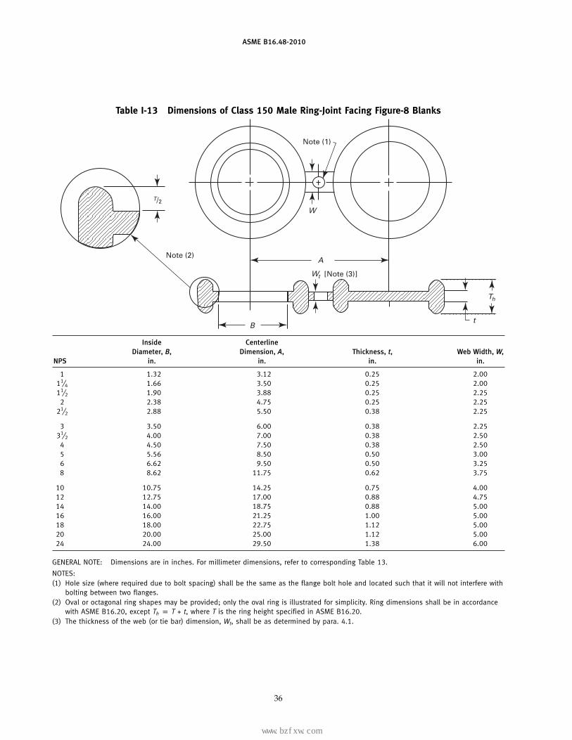
Table I-13 Dimensions of Class 150 Male Ring-Joint Facing Figure-8 Blanks
Note (1)
A
W
[Note (3)]
Note (2)
t
Th
Wt
B
T/2
Inside CenterlineDiameter, B, Dimension, A, Thickness, t, Web Width, W,
NPS in. in. in. in.
1 1.32 3.12 0.25 2.0011⁄4 1.66 3.50 0.25 2.0011⁄2 1.90 3.88 0.25 2.25
2 2.38 4.75 0.25 2.2521⁄2 2.88 5.50 0.38 2.25
3 3.50 6.00 0.38 2.2531⁄2 4.00 7.00 0.38 2.50
4 4.50 7.50 0.38 2.505 5.56 8.50 0.50 3.006 6.62 9.50 0.50 3.258 8.62 11.75 0.62 3.75
10 10.75 14.25 0.75 4.0012 12.75 17.00 0.88 4.7514 14.00 18.75 0.88 5.0016 16.00 21.25 1.00 5.0018 18.00 22.75 1.12 5.0020 20.00 25.00 1.12 5.0024 24.00 29.50 1.38 6.00
GENERAL NOTE: Dimensions are in inches. For millimeter dimensions, refer to corresponding Table 13.
NOTES:(1) Hole size (where required due to bolt spacing) shall be the same as the flange bolt hole and located such that it will not interfere with
bolting between two flanges.(2) Oval or octagonal ring shapes may be provided; only the oval ring is illustrated for simplicity. Ring dimensions shall be in accordance
with ASME B16.20, except Th p T + t, where T is the ring height specified in ASME B16.20.(3) The thickness of the web (or tie bar) dimension, Wt, shall be as determined by para. 4.1.
36
标准分享网 www.bzfxw.com 免费下载
www.bzfxw.com
ASME B16.48-2010
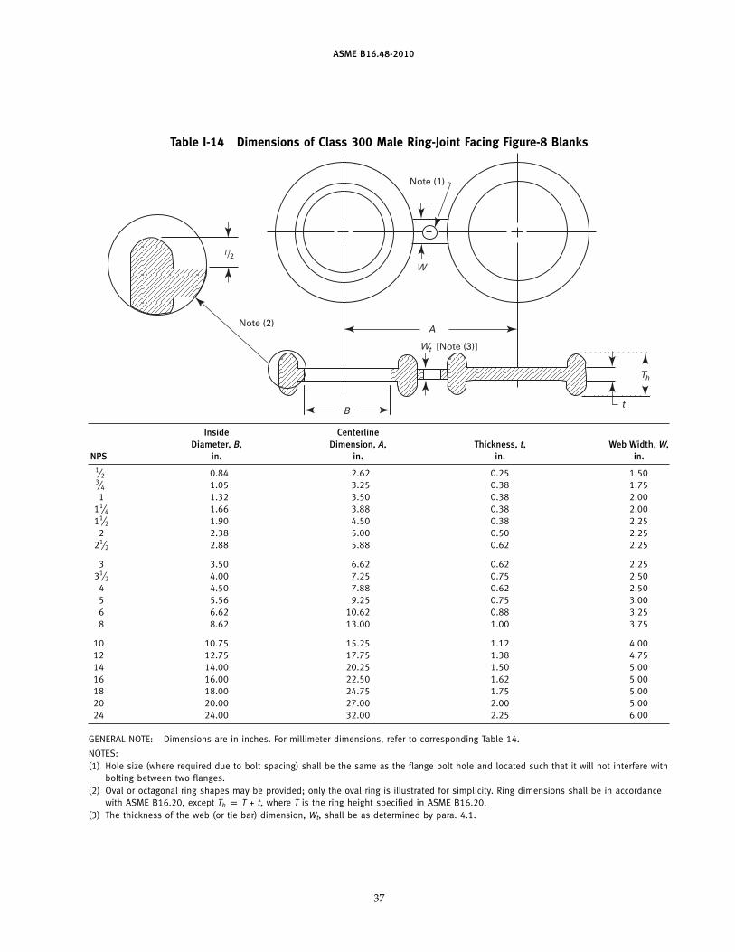
Table I-14 Dimensions of Class 300 Male Ring-Joint Facing Figure-8 Blanks
Note (1)
A
W
[Note (3)]
Note (2)
t
Th
Wt
B
T/2
Inside CenterlineDiameter, B, Dimension, A, Thickness, t, Web Width, W,
NPS in. in. in. in.1⁄2 0.84 2.62 0.25 1.503⁄4 1.05 3.25 0.38 1.751 1.32 3.50 0.38 2.00
11⁄4 1.66 3.88 0.38 2.0011⁄2 1.90 4.50 0.38 2.25
2 2.38 5.00 0.50 2.2521⁄2 2.88 5.88 0.62 2.25
3 3.50 6.62 0.62 2.2531⁄2 4.00 7.25 0.75 2.50
4 4.50 7.88 0.62 2.505 5.56 9.25 0.75 3.006 6.62 10.62 0.88 3.258 8.62 13.00 1.00 3.75
10 10.75 15.25 1.12 4.0012 12.75 17.75 1.38 4.7514 14.00 20.25 1.50 5.0016 16.00 22.50 1.62 5.0018 18.00 24.75 1.75 5.0020 20.00 27.00 2.00 5.0024 24.00 32.00 2.25 6.00
GENERAL NOTE: Dimensions are in inches. For millimeter dimensions, refer to corresponding Table 14.
NOTES:(1) Hole size (where required due to bolt spacing) shall be the same as the flange bolt hole and located such that it will not interfere with
bolting between two flanges.(2) Oval or octagonal ring shapes may be provided; only the oval ring is illustrated for simplicity. Ring dimensions shall be in accordance
with ASME B16.20, except Th p T + t, where T is the ring height specified in ASME B16.20.(3) The thickness of the web (or tie bar) dimension, Wt, shall be as determined by para. 4.1.
37
www.bzfxw.com
ASME B16.48-2010
Table I-15 Dimensions of Class 600 Male Ring-Joint Facing Figure-8 Blanks
Note (1)
A
W
[Note (3)]
Note (2)
t
Th
Wt
B
T/2
Inside CenterlineDiameter, B, Dimension, A, Thickness, t, Web Width, W,
NPS in. in. in. in.1⁄2 0.84 2.62 0.25 1.503⁄4 1.05 3.25 0.38 1.751 1.32 3.50 0.38 2.00
11⁄4 1.66 3.88 0.38 2.2511⁄2 1.90 4.50 0.38 2.25
2 2.38 5.00 0.50 2.0021⁄2 2.88 5.88 0.62 2.25
3 3.50 6.62 0.62 2.6231⁄2 4.00 7.25 0.75 2.62
4 4.50 8.50 0.75 2.885 5.56 10.50 0.88 2.886 6.62 11.50 1.12 2.888 8.62 13.75 1.38 3.25
10 10.75 17.00 1.62 4.7512 12.75 19.25 1.88 4.7514 14.00 20.75 2.00 4.7516 16.00 23.75 2.25 5.0018 18.00 25.75 2.50 5.2520 20.00 28.50 2.75 5.0024 24.00 33.00 3.25 6.00
GENERAL NOTE: Dimensions are in inches. For millimeter dimensions, refer to corresponding Table 15.
NOTES:(1) Hole size (where required due to bolt spacing) shall be the same as the flange bolt hole and located such that it will not interfere with
bolting between two flanges.(2) Oval or octagonal ring shapes may be provided; only the oval ring is illustrated for simplicity. Ring dimensions shall be in accordance
with ASME B16.20, except Th p T + t, where T is the ring height specified in ASME B16.20.(3) The thickness of the web (or tie bar) dimension, Wt, shall be as determined by para. 4.1.
38
标准分享网 www.bzfxw.com 免费下载
www.bzfxw.com
ASME B16.48-2010
Table I-16 Dimensions of Class 900 Male Ring-Joint Facing Figure-8 Blanks
Note (1)
A
W
[Note (3)]
Note (2)
t
Th
Wt
B
T/2
Inside CenterlineDiameter, B, Dimension, A, Thickness, t, Web Width, W,
NPS in. in. in. in.1⁄2 0.84 3.25 0.38 1.503⁄4 1.05 3.50 0.38 1.751 1.32 4.00 0.38 2.00
11⁄4 1.66 4.38 0.50 2.1211⁄2 1.90 4.88 0.50 2.12
2 2.38 6.50 0.62 2.00
21⁄2 2.88 7.50 0.75 2.123 3.50 7.50 0.75 2.624 4.50 9.25 1.00 2.885 5.56 11.00 1.12 2.886 6.62 12.50 1.25 2.888 8.62 15.50 1.62 3.12
10 10.75 18.50 1.88 4.7512 12.75 21.00 2.25 4.7514 14.00 22.00 2.38 4.7516 16.00 24.25 2.75 5.0018 18.00 27.00 3.00 5.2520 20.00 29.50 3.38 5.0024 24.00 35.50 3.88 6.00
GENERAL NOTE: Dimensions are in inches. For millimeter dimensions, refer to corresponding Table 16.
NOTES:(1) Hole size (where required due to bolt spacing) shall be the same as the flange bolt hole and located such that it will not interfere with
bolting between two flanges.(2) Oval or octagonal ring shapes may be provided; only the oval ring is illustrated for simplicity. Ring dimensions shall be in accordance
with ASME B16.20, except Th p T + t, where T is the ring height specified in ASME B16.20.(3) The thickness of the web (or tie bar) dimension, Wt, shall be as determined by para. 4.1.
39
www.bzfxw.com
ASME B16.48-2010
Table I-17 Dimensions of Class 1500 Male Ring-Joint Facing Figure-8 Blanks
Note (1)
A
W
[Note (3)]
Note (2)
t
Th
Wt
B
T/2
Inside CenterlineDiameter, B, Dimension, A, Thickness, t, Web Width, W,
NPS in. in. in. in.1⁄2 0.84 3.25 0.38 1.503⁄4 1.05 3.50 0.38 1.751 1.32 4.00 0.50 2.12
11⁄4 1.66 4.38 0.50 2.1211⁄2 1.90 4.88 0.62 2.25
2 2.38 6.50 0.75 2.12
21⁄2 2.88 7.50 0.88 2.253 3.50 8.00 1.12 2.884 4.50 9.50 1.25 3.005 5.56 11.50 1.50 3.006 6.62 12.50 1.62 3.128 8.62 15.50 2.00 3.38
10 10.75 19.00 2.50 5.2512 12.75 22.50 2.88 5.2514 14.00 25.00 3.12 5.5016 16.00 27.75 3.50 5.7518 18.00 30.50 3.88 6.0020 20.00 32.75 4.25 6.5024 24.00 39.00 5.00 7.00
GENERAL NOTE: Dimensions are in inches. For millimeter dimensions, refer to corresponding Table 17.
NOTES:(1) Hole size (where required due to bolt spacing) shall be the same as the flange bolt hole and located such that it will not interfere with
bolting between two flanges.(2) Oval or octagonal ring shapes may be provided; only the oval ring is illustrated for simplicity. Ring dimensions shall be in accordance
with ASME B16.20, except Th p T + t, where T is the ring height specified in ASME B16.20.(3) The thickness of the web (or tie bar) dimension, Wt, shall be as determined by para. 4.1.
40
标准分享网 www.bzfxw.com 免费下载
www.bzfxw.com
ASME B16.48-2010
Table I-18 Dimensions of Class 2500 Male Ring-Joint Facing Figure-8 Blanks
Note (1)
A
W
[Note (3)]
Note (2)
t
Th
Wt
B
T/2
Inside CenterlineDiameter, B, Dimension, A, Thickness, t, Web Width, W,
NPS in. in. in. in.1⁄2 0.84 3.50 0.50 1.623⁄4 1.05 3.75 0.62 1.881 1.32 4.25 0.62 2.12
11⁄4 1.66 5.12 0.75 2.1211⁄2 1.90 5.75 0.88 2.38
2 2.38 6.75 1.00 2.25
21⁄2 2.88 7.75 1.12 2.383 3.50 9.00 1.25 3.004 4.50 10.75 1.50 3.255 5.56 12.75 1.88 3.506 6.62 14.50 2.25 3.758 8.62 17.25 2.75 3.75
10 10.75 21.25 3.25 3.7512 12.75 24.38 3.88 6.00
GENERAL NOTE: Dimensions are in inches. For millimeter dimensions, refer to corresponding Table 18.
NOTES:(1) Hole size (where required due to bolt spacing) shall be the same as the flange bolt hole and located such that it will not interfere with
bolting between two flanges.(2) Oval or octagonal ring shapes may be provided: only the oval ring is illustrated for simplicity. Ring dimensions shall be in accordance
with ASME B16.20, except Th p T + t, where T is the ring height specified in ASME B16.20.(3) The thickness of the web (or tie bar) dimension, Wt, shall be as determined by para. 4.1.
41
www.bzfxw.com
(10)
ASME B16.48-2010
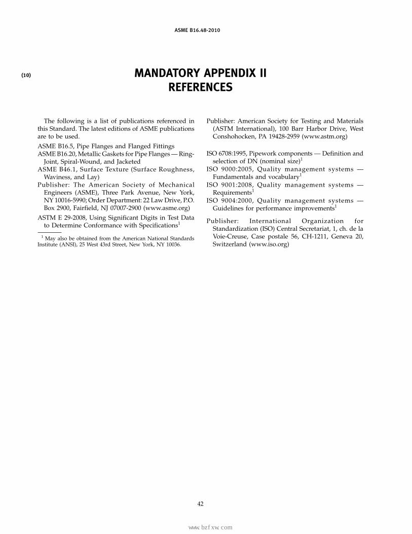
MANDATORY APPENDIX IIREFERENCES
The following is a list of publications referenced inthis Standard. The latest editions of ASME publicationsare to be used.
ASME B16.5, Pipe Flanges and Flanged FittingsASME B16.20, Metallic Gaskets for Pipe Flanges — Ring-
Joint, Spiral-Wound, and JacketedASME B46.1, Surface Texture (Surface Roughness,
Waviness, and Lay)Publisher: The American Society of Mechanical
Engineers (ASME), Three Park Avenue, New York,NY 10016-5990; Order Department: 22 Law Drive, P.O.Box 2900, Fairfield, NJ 07007-2900 (www.asme.org)
ASTM E 29-2008, Using Significant Digits in Test Datato Determine Conformance with Specifications1
1 May also be obtained from the American National StandardsInstitute (ANSI), 25 West 43rd Street, New York, NY 10036.
42
Publisher: American Society for Testing and Materials(ASTM International), 100 Barr Harbor Drive, WestConshohocken, PA 19428-2959 (www.astm.org)
ISO 6708:1995, Pipework components — Definition andselection of DN (nominal size)1
ISO 9000:2005, Quality management systems —Fundamentals and vocabulary1
ISO 9001:2008, Quality management systems —Requirements1
ISO 9004:2000, Quality management systems —Guidelines for performance improvements1
Publisher: International Organization forStandardization (ISO) Central Secretariat, 1, ch. de laVoie-Creuse, Case postale 56, CH-1211, Geneva 20,Switzerland (www.iso.org)
标准分享网 www.bzfxw.com 免费下载
www.bzfxw.com
ASME B16.48-2010
NONMANDATORY APPENDIX AQUALITY SYSTEM PROGRAM
The products manufactured in accordance with thisStandard shall be produced under a quality system pro-gram following the principles of an appropriate stan-dard from the IS0 9000 series.1 A determination of theneed for registration and/or certification of the product
1 The series is also available from the American NationalStandards Institute (ANSI) and the American Society for QualityControl (ASQ) as American National Standards that are identifiedby a prefix “Q” replacing the prefix “ISO.” Each standard of theseries is listed under Mandatory Appendix II.
43
manufacturer’s quality system program by an indepen-dent organization shall be the responsibility of the manu-facturer. The detailed documentation demonstratingprogram compliance shall be available to the purchaserat the manufacturer ’s facility. A written summarydescription of the program utilized by the product man-ufacturer shall be available to the purchaser uponrequest. The product manufacturer is defined as theentity whose name or trademark appears on the productin accordance with the marking or identification require-ments of this Standard.
(10)
www.bzfxw.com
B16 AMERICAN NATIONAL STANDARDS FOR PIPING,PIPE FLANGES, FITTINGS, AND VALVES
Gray Iron Pipe Flanges and Flanged Fittings (Classes 25, 125, and 250) . . . . . . . . . . . . . . . . . . . . . . . . . . . . . . . . . . . . . . . . . . . . . . . B16.1-2005Malleable Iron Threaded Fittings: Classes 150 and 300. . . . . . . . . . . . . . . . . . . . . . . . . . . . . . . . . . . . . . . . . . . . . . . . . . . . . . . . . . . . . B16.3-2006Gray Iron Threaded Fittings: Classes 125 and 250 . . . . . . . . . . . . . . . . . . . . . . . . . . . . . . . . . . . . . . . . . . . . . . . . . . . . . . . . . . . . . . . . . B16.4-2006Pipe Flanges and Flanged Fittings NPS 1⁄2 Through NPS 24 Metric/Inch Standard . . . . . . . . . . . . . . . . . . . . . . . . . . . . . . . . . . . . . . . . B16.5-2009Factory-Made Wrought Buttwelding Fittings. . . . . . . . . . . . . . . . . . . . . . . . . . . . . . . . . . . . . . . . . . . . . . . . . . . . . . . . . . . . . . . . . . . . . . . B16.9-2007Face-to-Face and End-to-End Dimensions of Valves . . . . . . . . . . . . . . . . . . . . . . . . . . . . . . . . . . . . . . . . . . . . . . . . . . . . . . . . . . . . . . . B16.10-2009Forged Fittings, Socket-Welding and Threaded . . . . . . . . . . . . . . . . . . . . . . . . . . . . . . . . . . . . . . . . . . . . . . . . . . . . . . . . . . . . . . . . . . . B16.11-2009Cast Iron Threaded Drainage Fittings . . . . . . . . . . . . . . . . . . . . . . . . . . . . . . . . . . . . . . . . . . . . . . . . . . . . . . . . . . . . . . . . . . . .B16.12-2009 (R2014)Ferrous Pipe Plugs, Bushings, and Locknuts with Pipe Threads . . . . . . . . . . . . . . . . . . . . . . . . . . . . . . . . . . . . . . . . . . . . . . . . . . . . . B16.14-1991Cast Copper Alloy Threaded Fittings. . . . . . . . . . . . . . . . . . . . . . . . . . . . . . . . . . . . . . . . . . . . . . . . . . . . . . . . . . . . . . . . . . . . . . . . . . . . B16.15-2006Cast Copper Alloy Solder Joint Pressure Fittings . . . . . . . . . . . . . . . . . . . . . . . . . . . . . . . . . . . . . . . . . . . . . . . . . . . . . . . . . . .B16.18-2001 (R2005)Metallic Gaskets for Pipe Flanges: Ring-Joint, Spiral-Wound, and Jacketed . . . . . . . . . . . . . . . . . . . . . . . . . . . . . . . . . . . . . . . . . . . . . B16.20-2007Nonmetallic Flat Gaskets for Pipe Flanges . . . . . . . . . . . . . . . . . . . . . . . . . . . . . . . . . . . . . . . . . . . . . . . . . . . . . . . . . . . . . . . . . . . . . . . B16.21-2005Wrought Copper and Copper Alloy Solder Joint Pressure Fittings. . . . . . . . . . . . . . . . . . . . . . . . . . . . . . . . . . . . . . . . . . . . . .B16.22-2001 (R2005)Cast Copper Alloy Solder Joint Drainage Fittings: DWV . . . . . . . . . . . . . . . . . . . . . . . . . . . . . . . . . . . . . . . . . . . . . . . . . . . . . .B16.23-2002 (R2006)Cast Copper Alloy Pipe Flanges and Flanged Fittings: Classes 150, 300, 600, 900, 1500, and 2500 . . . . . . . . . . . . . . . . . . . . . . . B16.24-2006Buttwelding Ends. . . . . . . . . . . . . . . . . . . . . . . . . . . . . . . . . . . . . . . . . . . . . . . . . . . . . . . . . . . . . . . . . . . . . . . . . . . . . . . . . . . . . . . . . . . B16.25-2007Cast Copper Alloy Fittings for Flared Copper Tubes. . . . . . . . . . . . . . . . . . . . . . . . . . . . . . . . . . . . . . . . . . . . . . . . . . . . . . . . . . . . . . . . B16.26-2006Wrought Steel Buttwelding Short Radius Elbows and Returns . . . . . . . . . . . . . . . . . . . . . . . . . . . . . . . . . . . . . . . . . . . . . . . . . . . . . . . B16.28-1994Wrought Copper and Wrought Copper Alloy Solder Joint Drainage Fittings — DWV. . . . . . . . . . . . . . . . . . . . . . . . . . . . . . . . . . . . . . . B16.29-2007Manually Operated Metallic Gas Valves for Use in Gas Piping Systems up to 125 psi
(Sizes NPS 1⁄2 Through NPS 2) . . . . . . . . . . . . . . . . . . . . . . . . . . . . . . . . . . . . . . . . . . . . . . . . . . . . . . . . . . . . . . . . . . . . . . .B16.33-2002 (R2007)Valves — Flanged, Threaded, and Welding End. . . . . . . . . . . . . . . . . . . . . . . . . . . . . . . . . . . . . . . . . . . . . . . . . . . . . . . . . . . . . . . . . . . B16.34-2004Orifice Flanges . . . . . . . . . . . . . . . . . . . . . . . . . . . . . . . . . . . . . . . . . . . . . . . . . . . . . . . . . . . . . . . . . . . . . . . . . . . . . . . . . . . . . . . . . . . . . B16.36-2009Large Metallic Valves for Gas Distribution Manually Operated, NPS 21⁄2 (DN 65)
to NPS 12 (DN 300), 125 psig (8.6 bar) Maximum. . . . . . . . . . . . . . . . . . . . . . . . . . . . . . . . . . . . . . . . . . . . . . . . . . . . . . . . . . . . . . B16.38-2007Malleable Iron Threaded Pipe Unions: Classes 150, 250, and 300. . . . . . . . . . . . . . . . . . . . . . . . . . . . . . . . . . . . . . . . . . . . . . . . . . . B16.39-2009Manually Operated Thermoplastic Gas Shutoffs and Valves in Gas Distribution Systems . . . . . . . . . . . . . . . . . . . . . . . . . . . . . . . . . B16.40-2008Functional Qualification Requirements for Power Operated Active Valve Assemblies for Nuclear Power Plants . . . . . . . . .B16.41-1983 (R1989)Ductile Iron Pipe Flanges and Flanged Fittings: Classes 150 and 300 . . . . . . . . . . . . . . . . . . . . . . . . . . . . . . . . . . . . . . . . .B16.42-1998 (R2006)Manually Operated Metallic Gas Valves for Use in Aboveground Piping Systems Up To 5 PSI . . . . . . . . . . . . . . . . . . . . . .B16.44-2002 (R2007)Cast Iron Fittings for Sovent® Drainage Systems. . . . . . . . . . . . . . . . . . . . . . . . . . . . . . . . . . . . . . . . . . . . . . . . . . . . . . . . . . .B16.45-1998 (R2006)Large Diameter Steel Flanges NPS 26 Through NPS 60 Metric/Inch Standard . . . . . . . . . . . . . . . . . . . . . . . . . . . . . . . . . . . . . . . . . . B16.47-2006Line Blanks . . . . . . . . . . . . . . . . . . . . . . . . . . . . . . . . . . . . . . . . . . . . . . . . . . . . . . . . . . . . . . . . . . . . . . . . . . . . . . . . . . . . . . . . . . . . . . . B16.48-2010Factory-Made Wrought Steel Buttwelding Induction Bends for Transportation and Distribution Systems . . . . . . . . . . . . . . . . . . . . . B16.49-2007Wrought Copper and Copper Alloy Braze-Joint Pressure Fittings . . . . . . . . . . . . . . . . . . . . . . . . . . . . . . . . . . . . . . . . . . . . . .B16.50-2001 (R2008)
The ASME Publications Catalog shows a complete list of all the Standards published by the Society. For a complimentary catalog, or the latestinformation about our publications, call 1-800-THE-ASME (1-800-843-2763).
标准分享网 www.bzfxw.com 免费下载

www.bzfxw.comINTENTIONALLY LEFT BLANK

www.bzfxw.com
J14410
ASME B16.48-2010
标准分享网 www.bzfxw.com 免费下载