Embed Size (px)
Citation preview
저 시-비 리- 경 지 2.0 한민
는 아래 조건 르는 경 에 한하여 게
l 저 물 복제, 포, 전송, 전시, 공연 송할 수 습니다.
다 과 같 조건 라야 합니다:
l 하는, 저 물 나 포 경 , 저 물에 적 된 허락조건 명확하게 나타내어야 합니다.
l 저 터 허가를 면 러한 조건들 적 되지 않습니다.
저 에 른 리는 내 에 하여 향 지 않습니다.
것 허락규약(Legal Code) 해하 쉽게 약한 것 니다.
Disclaimer
저 시. 하는 원저 를 시하여야 합니다.
비 리. 하는 저 물 리 목적 할 수 없습니다.
경 지. 하는 저 물 개 , 형 또는 가공할 수 없습니다.
공학석사 학위논문
Needle steering scheme within
limited DOFs for MR-guided
breast needle intervention robot
MR 유도 유방 바늘 중재시술 로봇을 위한
한정된 자유도 안에서 바늘 스티어링 전략
2017년 2월
서울대학교 대학원
기계항공공학부
이 정 환
i
Abstract
The MR-guided needle-based procedure is commonly
performed for breast diagnosis and treatment. Accurate needle tip
placement is important for the success of the procedure, because
misplacement of the needle tip can lead to unsuccessful treatment
and misdiagnosis. In addition, developing a needle steering robotic
system with high precision and dexterity is required to avoid
important organs, minimizing patients’ trauma. However, due to the
strong magnetic field and relatively small MRI bore size, developing
a high degrees of freedom (DOFs) robotic system is challenging. This
work proposes a needle steering scheme that can be effectively
utilized in an MR-guided breast needle intervention robot under
limited space of MRI bore with minimizing system size increase. To
overcome the space limitation and avoid critical structures in front of
the lesion, a pivot is used to change the needle insertion direction.
We devise the needle pivoting breast plate to increase needle tip’s
DOFs and an estimation model of the needle deflection with a pivoted
super-elastic flexible needle made of Nitinol. This computational
model is based on large deflection beam theory and is employed for
robot control. Open-loop needle targeting experiments under
infrared tracking cameras are performed to verify the proposed

ii
scheme. The average targeting error and the standard deviation is
4.42 ± 2.58 mm.
Keyword: MR-guided breast needle intervention robot, Needle
pivoting breast plate, Needle Steering, Super-elastic flexible needle,
Needle deflection estimation, Large deflection beam theory
Student Number: 2013-23084

iii
Table of Contents
Chapter 1. Introduction ...................................................................... 1
Chapter 2. Materials ........................................................................... 4
2.1. MR-guided breast needle intervention robot system ........... 4
2.2. Needle pivoting breast plate ................................................... 7
Chapter 3. Methods .......................................................................... 10
3.1. Needle Steering Procedure ................................................... 10
3.2. Robot pose estimation ........................................................... 12
3.2.1. Large deflection beam theory ........................................ 13
3.2.2. Estimation of external force........................................... 18
3.2.3. Measurement of bending stiffness ................................. 19
3.2.4. Define the robot movement direction ............................ 25
3.3. Optimal path selection scenario ............................................ 27
Chapter 4. Results ............................................................................ 30
4.1. In vitro test ............................................................................ 30
4.1.1. Experiment setup ............................................................ 30
4.1.2. Target error .................................................................... 32
Chapter 5. Discussion ....................................................................... 36
Bibliography ...................................................................................... 40
Abstract in Korean ........................................................................... 43

iv
List of Tables
Table 1. Nitinol needle specification ................................................ 21
Table 2. Targeting error results ...................................................... 33
List of Figures
Figure 1. Concept of a pivot ............................................................... 3
Figure 2. Developed MR-guided breast needle intervention robot 4
Figure 3. Needle pivoting breast plate ............................................... 7
Figure 4. Overall commercial breast coil and needle pivoting breast
plate .................................................................................................... 7
Figure 5. Extended robot motion by a pivot ...................................... 9
Figure 6. Needle steering procedure ............................................... 11
Figure 7. Schematic of the pivot with the flexible needle ............... 12
Figure 8. Large deflection of cantilever beam ................................. 13
Figure 9. Approximated simple spring system ................................ 18
Figure 10. Typical loading and unloading behavior of super-elastic
Ni-Ti ................................................................................................ 20
Figure 11. Setup for measuring the needle bending stiffness ........ 21
Figure 12. A 3D visualization of the measurement results ............. 22
Figure 13. Deflection–Load relationship at several lengths ............ 23

v
Figure 14. Bending stiffness 𝒌𝒃 vs. length of needle 𝑳 .................. 23
Figure 15. Needle deflection vs. insertion angle ............................. 25
Figure 16. Set plane of motion ......................................................... 27
Figure 17. Estimated needle path to reach the target ..................... 28
Figure 18. Optimal path selection scenario ..................................... 28
Figure 19. Experimental setup using IR tracking cameras ............. 31
Figure 20. Selected holes for the experiment ................................. 32
Figure 21. Box whisker chart of the targeting error ....................... 33
Figure 22. A 3D visualization of the targeting result ...................... 35
Figure 23. The gap between the needle and wall of the hole ......... 37
Figure 24. Developed MRI viewer software .................................... 38
Figure 25. Schematic of the MRI feedback control ......................... 38
1
Chapter 1. Introduction
Breast cancer is the most frequently diagnosed cancer and is
the second leading cause of cancer death after lung cancer. [1]
Needle-based procedures are the most common clinical
interventions for breast cancer and are used for biopsy,
brachytherapy, and ablation. [2, 3] Because misdiagnosis or
unsuccessful treatment might occur due to the misplacement of the
needle tip, accurate needle tip placement is critical for procedure’s
success rate. Image-guided needle intervention is performed to
improve the needle tip placement accuracy. Since Magnetic
Resonance Image (MRI) can provide superior soft tissue contrast
without harmful ionizing radiation, it has recently gained popularity.
[4, 5] Constrained by the limited space of the MRI scanner bore,
breast needle intervention is currently performed outside of the MRI
bore and based on MR images. Repeated needle insertion is required
to locate needle tip at the desired position, and such “Trial and error”–
based needle insertion may increase positioning errors and cause
patients undue trauma. Hence, a precise multiple degrees of freedom
(DOFs) robot is required so that the patients can remain inside the
MRI bore and accurate needle tip placement can be achieved. This
will allow the avoidance of multiple iterations and minimize
positioning errors during needle intervention. [6, 7]
2
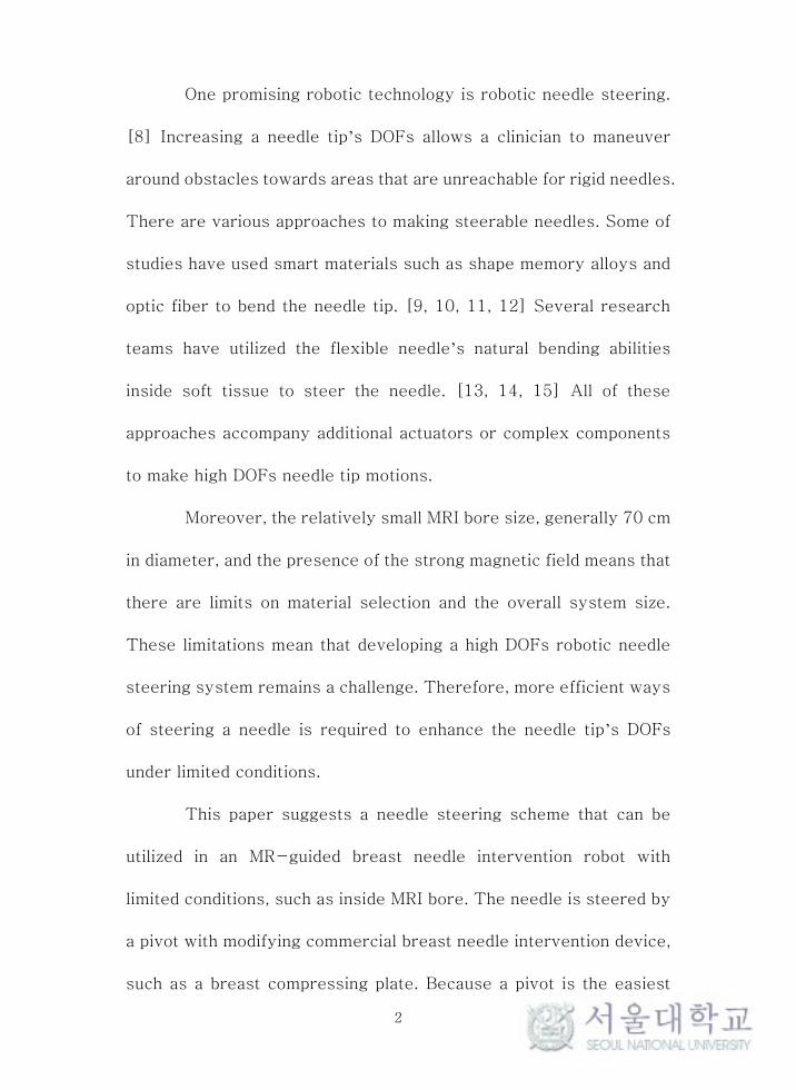
One promising robotic technology is robotic needle steering.
[8] Increasing a needle tip’s DOFs allows a clinician to maneuver
around obstacles towards areas that are unreachable for rigid needles.
There are various approaches to making steerable needles. Some of
studies have used smart materials such as shape memory alloys and
optic fiber to bend the needle tip. [9, 10, 11, 12] Several research
teams have utilized the flexible needle’s natural bending abilities
inside soft tissue to steer the needle. [13, 14, 15] All of these
approaches accompany additional actuators or complex components
to make high DOFs needle tip motions.
Moreover, the relatively small MRI bore size, generally 70 cm
in diameter, and the presence of the strong magnetic field means that
there are limits on material selection and the overall system size.
These limitations mean that developing a high DOFs robotic needle
steering system remains a challenge. Therefore, more efficient ways
of steering a needle is required to enhance the needle tip’s DOFs
under limited conditions.
This paper suggests a needle steering scheme that can be
utilized in an MR-guided breast needle intervention robot with
limited conditions, such as inside MRI bore. The needle is steered by
a pivot with modifying commercial breast needle intervention device,
such as a breast compressing plate. Because a pivot is the easiest
3
way to change needle tip direction and commercial beast compressing
plate can work as pivot points with little shape changes, pivots are
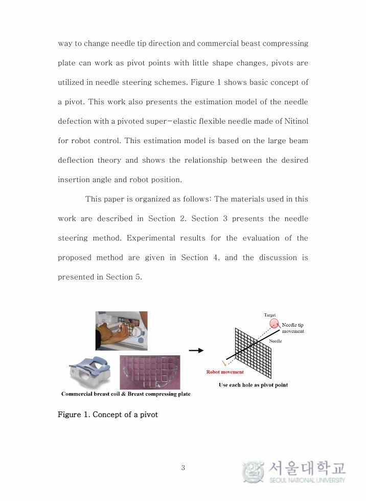
utilized in needle steering schemes. Figure 1 shows basic concept of
a pivot. This work also presents the estimation model of the needle
defection with a pivoted super-elastic flexible needle made of Nitinol
for robot control. This estimation model is based on the large beam
deflection theory and shows the relationship between the desired
insertion angle and robot position.
This paper is organized as follows: The materials used in this
work are described in Section 2. Section 3 presents the needle
steering method. Experimental results for the evaluation of the
proposed method are given in Section 4, and the discussion is
presented in Section 5.
Figure 1. Concept of a pivot
4
Chapter 2. Materials
2.1. MR-guided breast needle intervention robot system
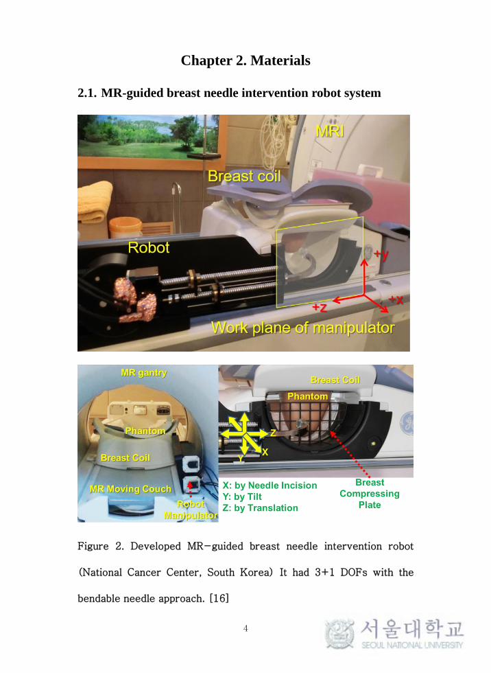
Figure 2. Developed MR-guided breast needle intervention robot
(National Cancer Center, South Korea) It had 3+1 DOFs with the
bendable needle approach. [16]

5
An MR-guided breast needle intervention robot developed by
the National Cancer Center in South Korea was used in this work.
[16] (Figure 2)
This robot is designed to be placed inside an MRI bore and
operated therein under continuous MRI guidance. The robot can be
attached to a commercial breast coil (GE, Germany), and this feature
allows the robot to be located beside the patient. This design was
intended to overcome the space limitation.
This robot is consisted of two main drivers for manipulator
and pre-curved end effector. A manipulator to hold and move the
pre-curved end effector was designed with a 2 DOFs sliding
mechanism with two spindles. The end effector slides in the Z
direction while two spindles drive in the same direction. A linear
slider in the center holds the end effector with a pivot. Therefore,
when the upper spindle and lower spindle move in different directions,
the end effector tilts. With this 2 DOFs sliding mechanism, the end
effector, in this case the needle exit point, is positioned on the plane
parallel to the patient’s sagittal plane (Y-Z plane).
Since this robot system located beside patient, needle
direction should have to change 90°for insertion. The 90° direction
change in the pre-curved end effector necessitates flexibility and
super-elasticity characteristics. Therefore, a super-elastic Nitinol
6
tube is chosen because its recovery characteristic without permanent
deformation after bending.
The pre-curved end effector also has two spindle motors that
can move the needle driver and pusher driver separately. These two
spindle motors can make needle’s back and forth motion. In addition,
concentric dual needles, which can be utilized in many needle
intervention procedures such as biopsy, inserting a marker seed and
a drug capsule, can be applied in this robot.
In short, developed MR-guided breast needle intervention
robot has total 3 + 1 DOFs motion including 2 DOFs manipulator
motion and 1 + 1 DOFs needle sliding (1 for inner needle and the
other for outer needle). With this 3 DOFs robot motion, this robot
system can send the needle point anywhere inside breast. However,
this robot can not avoid obstacles inside the breast because needle
insertion direction is only perpendicular to the patient’s sagittal
plane (Y-Z plane). For avoiding obstacles inside breast, additional
movement of needle should have to generate. To make needle’s
extended movement such as steering, we utilize the needle pivoting
breast plate.
7
2.2. Needle pivoting breast plate
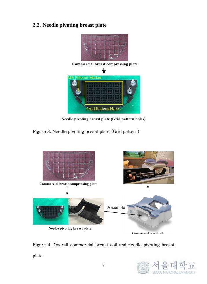
Figure 3. Needle pivoting breast plate (Grid pattern)
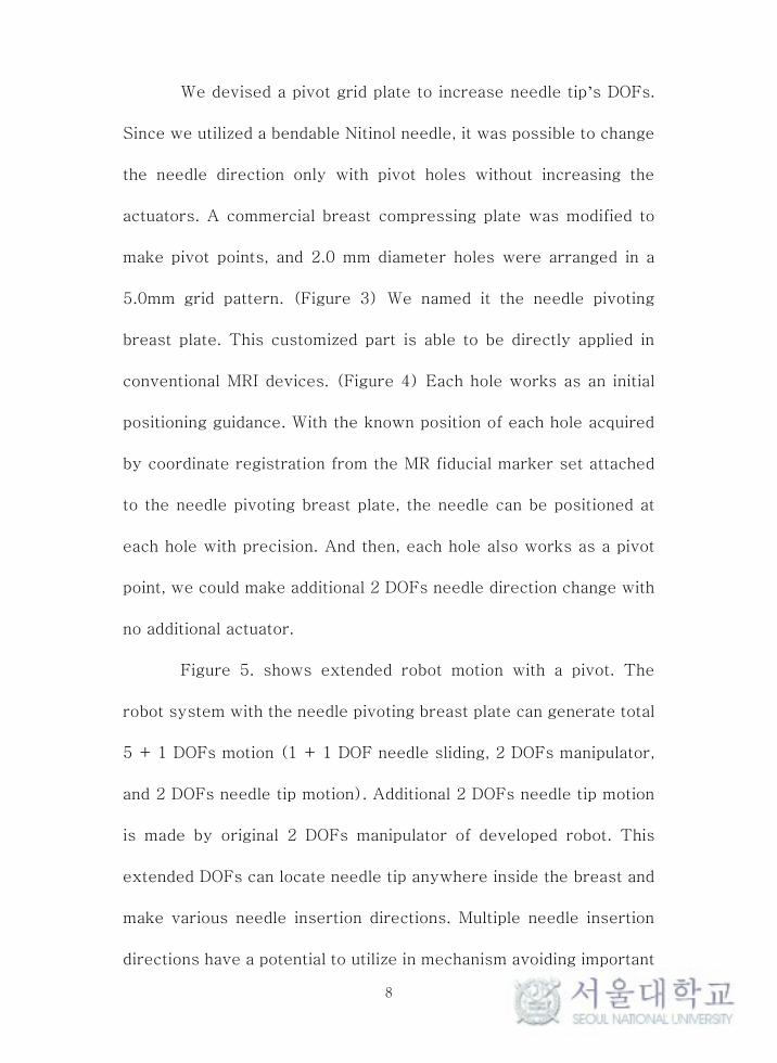
Figure 4. Overall commercial breast coil and needle pivoting breast
plate
8
We devised a pivot grid plate to increase needle tip’s DOFs.
Since we utilized a bendable Nitinol needle, it was possible to change
the needle direction only with pivot holes without increasing the
actuators. A commercial breast compressing plate was modified to
make pivot points, and 2.0 mm diameter holes were arranged in a
5.0mm grid pattern. (Figure 3) We named it the needle pivoting
breast plate. This customized part is able to be directly applied in
conventional MRI devices. (Figure 4) Each hole works as an initial
positioning guidance. With the known position of each hole acquired
by coordinate registration from the MR fiducial marker set attached
to the needle pivoting breast plate, the needle can be positioned at
each hole with precision. And then, each hole also works as a pivot
point, we could make additional 2 DOFs needle direction change with
no additional actuator.
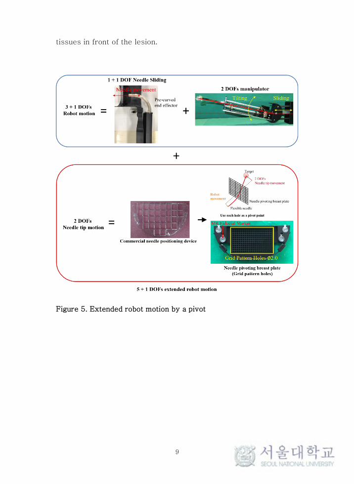
Figure 5. shows extended robot motion with a pivot. The
robot system with the needle pivoting breast plate can generate total
5 + 1 DOFs motion (1 + 1 DOF needle sliding, 2 DOFs manipulator,
and 2 DOFs needle tip motion). Additional 2 DOFs needle tip motion
is made by original 2 DOFs manipulator of developed robot. This
extended DOFs can locate needle tip anywhere inside the breast and
make various needle insertion directions. Multiple needle insertion
directions have a potential to utilize in mechanism avoiding important
9
tissues in front of the lesion.
Figure 5. Extended robot motion by a pivot

10
Chapter 3. Methods
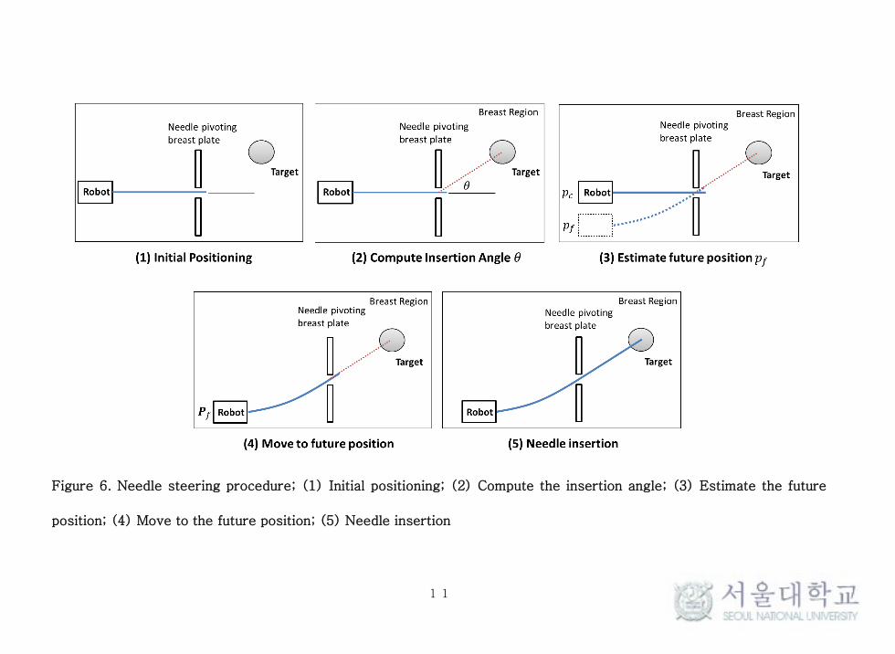
3.1. Needle steering procedure
The needle steering procedure using a pivot is comprised of
the following steps: (1) Initial positioning of the desired needle
pivoting breast plate’s hole; (2) Compute the needle insertion angle
for the target position; (3) Estimate the robot’s future position to
determine the desired insertion angle; (4) Move to the future position;
(5) Needle insertion. (Figure 6)
There are two assumptions in robot control. First, the needle
has linear elasticity, which is a basic assumption of the large beam
deflection theory that is used to estimate the robot future position.
Second, the needle insertion path is straight. In this approach, the
needle’s natural deflection inside the tissue is negligible because of
the needle’s high rigidity.
11
Figure 6. Needle steering procedure; (1) Initial positioning; (2) Compute the insertion angle; (3) Estimate the future
position; (4) Move to the future position; (5) Needle insertion
12
3.2. Robot pose estimation
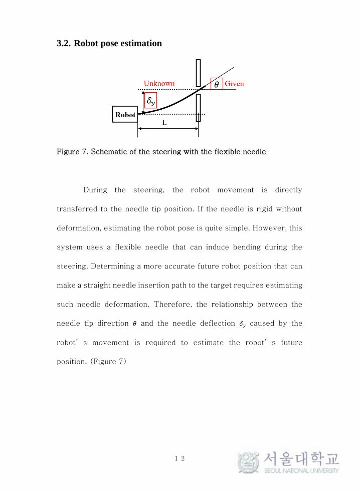
Figure 7. Schematic of the steering with the flexible needle
During the steering, the robot movement is directly
transferred to the needle tip position. If the needle is rigid without
deformation, estimating the robot pose is quite simple. However, this
system uses a flexible needle that can induce bending during the
steering. Determining a more accurate future robot position that can
make a straight needle insertion path to the target requires estimating
such needle deformation. Therefore, the relationship between the
needle tip direction 𝜃 and the needle deflection 𝛿𝑦 caused by the
robot’s movement is required to estimate the robot’s future
position. (Figure 7)
13
3.2.1. Large deflection beam theory
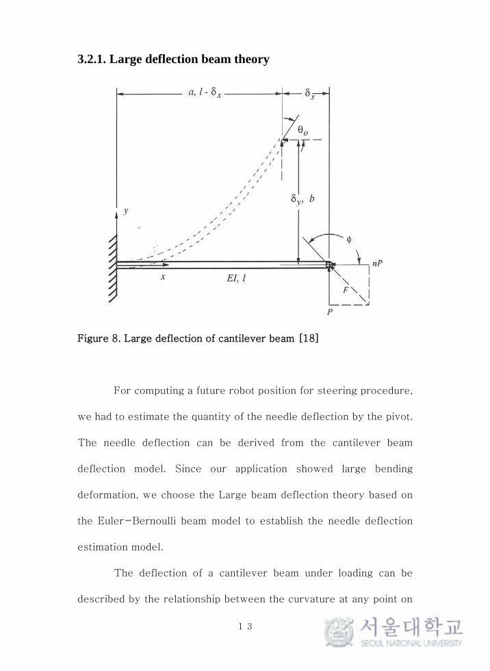
Figure 8. Large deflection of cantilever beam [18]
For computing a future robot position for steering procedure,
we had to estimate the quantity of the needle deflection by the pivot.
The needle deflection can be derived from the cantilever beam
deflection model. Since our application showed large bending
deformation, we choose the Large beam deflection theory based on
the Euler-Bernoulli beam model to establish the needle deflection
estimation model.
The deflection of a cantilever beam under loading can be
described by the relationship between the curvature at any point on

14
the beam and the applied moment at that point under the assumption
that the beam’s material remains linearly elastic. This relationship
is [17, 18]
𝜅 =𝑑𝜃
𝑑𝑠=
𝑀
𝐸𝐼 (1)
where 𝑑𝜃
𝑑𝑠 is the curvature of the beam and the rate of change of 𝜃
with respect to s. E is the modulus of elasticity for the material and I
is the moment of inertia for the cross-sectional area of the beam.
The internal moment at any point in the beam is given by
𝑀 = 𝑃(𝑎 − 𝑥) + 𝑛𝑃(𝑏 − 𝑦) (2)
where 𝑎 is the horizontal distance from the fixed end to the free end
and 𝑏 is the vertical distance of the free end from its undeflected
position. n is the ratio of the horizontal force to the vertical force.
(0 ≤ n ≤ 1) Substituting equation (1) to equation (2) yields
𝜅 =𝑑𝜃
𝑑𝑠=
𝑃
𝐸𝐼[(𝑎 − 𝑥) + 𝑛(𝑏 − 𝑦)] (3)
By differentiating equation (3) once with respect to s, we obtain

15
𝑑𝜅
𝑑𝑠=
𝑑2𝜃
𝑑𝑠2 =𝑃
𝐸𝐼(−
𝑑𝑥
𝑑𝑠− 𝑛
𝑑𝑦
𝑑𝑠) (4)
If 𝑑𝑥 , 𝑑𝑦 and 𝑑𝑠 are infinitesimal, we can express 𝑑𝑥
ds and
𝑑𝑦
ds as
𝑐𝑜𝑠𝜃 and 𝑠𝑖𝑛𝜃. Therefore, equation (4) can be expressed as follow
𝑑2𝜃
𝑑𝑠2 =−𝑃
𝐸𝐼(𝑛 𝑠𝑖𝑛𝜃 + 𝑐𝑜𝑠𝜃) (5)
The second order differential equation (5) for 𝜃 is
𝑑2𝜃
𝑑𝑠2 =𝑑
𝑑𝑠(𝑑𝜃
𝑑𝑠) (6)
By the chain rule, equation (6) can be written as
𝑑
𝑑𝑠(𝑑𝜃
𝑑𝑠) =
𝑑
𝑑𝜃(𝑑𝜃
𝑑𝑠)
𝑑𝜃
𝑑𝑠 (7)
By substituting curvature κ =𝑑𝜃
𝑑𝑠 to equation (7), we obtain
𝑑2𝜃
𝑑𝑠2 =𝑑κ
𝑑𝜃κ (8)

16
Equation (8) can be modified as follow
𝑑2𝜃
𝑑𝑠2 =𝑑
𝑑𝜃(κ2
2) (9)
After substituting equation (9) to equation (5) and integrating, we
obtain
∫𝑑 (𝜅2
2) = ∫
−𝑃
𝐸𝐼(𝑛 𝑠𝑖𝑛𝜃 + 𝑐𝑜𝑠𝜃)𝑑𝜃 (10)
Equation (10) is solved as
𝜅2
2=
𝑃
𝐸𝐼(𝑛 𝑐𝑜𝑠𝜃 − 𝑠𝑖𝑛𝜃) + 𝐶1 (11)
where 𝐶1 is integral constant. According to the figure 8, boundary
conditions are 𝑠 = 𝑙 , 𝜃 = 𝜃0 and 𝑑𝜃
𝑑𝑠= κ = 0 . Therefore, integral
constant 𝐶1 is derived as
𝐶1 =𝑃
𝐸𝐼(𝑠𝑖𝑛𝜃0 − 𝑛 𝑐𝑜𝑠𝜃0) (12)
By substituting equation (12) to equation (11), we obtain

17
𝜅 =𝑑𝜃
𝑑𝑠= √2
𝑃
𝐸𝐼(𝑠𝑖𝑛𝜃0 − 𝑛 𝑐𝑜𝑠𝜃0 − 𝑠𝑖𝑛𝜃 + 𝑛 𝑐𝑜𝑠𝜃) (13)
Let us assume that the horizontal force does not apply at the free end
(𝑛 = 0). Thus, equation (13) can be written as
𝜅 =𝑑𝜃
𝑑𝑠= √2
𝑃
𝐸𝐼(𝑠𝑖𝑛𝜃0 − 𝑠𝑖𝑛𝜃) (14)
Equation (14) is also expressed as
𝑑𝑠 = √𝐸𝐼
2𝑃
𝑑𝜃
√(𝑠𝑖𝑛𝜃0−𝑠𝑖𝑛𝜃) (15)
Where 𝑑𝑦
ds= 𝑠𝑖𝑛𝜃, equation (15) is re-written as
𝑑𝑦 = √𝐸𝐼
2𝑃
𝑠𝑖𝑛𝜃
√(𝑠𝑖𝑛𝜃0−𝑠𝑖𝑛𝜃)𝑑𝜃 (16)
Integrating both side and substituting the angle at the free end 𝜃0 to
𝜃 yields
𝛿𝑦 = 𝑦(𝜃0) = √𝐸𝐼
2𝑃∫
𝑠𝑖𝑛𝜃
√(𝑠𝑖𝑛𝜃0−𝑠𝑖𝑛𝜃)𝑑𝜃
𝜃0
0 (17)

18
𝛿𝑦 is the vertical deflection at the free end. The final equation can be
utilized in the estimation of the robot’s future pose.
3.2.2. Estimation of external force
Figure 9. Approximated simple spring system
Equation (17) shows the vertical deflection at the free end
when an external force is applied. However, deflection is induced by
robot base movement in this robot system. Thus, the external force
P in equation (17) is an unknown variable. The bending of the needle
can be regarded as a simple spring model to estimate the external
force P. (Figure 9) The resistance of a member against bending
deformation, the bending stiffness 𝑘𝑏, works as a spring constant in
this spring model. Thus, the restoration force applies at the pivot
point. The external force at the pivot point can be substituted for the
19
force of restoration. Then, the external force can be written as
𝑃 = 𝑘𝑏𝛿𝑦 (18)
𝑘𝑏 is the bending stiffness and 𝛿𝑦 is the deformation due to the
robot’s position change. Substituting equation (18) into equation
(17) allows us to write 𝛿𝑦 as
𝛿𝑦 = √𝐸𝐼
2𝑘𝑏𝐴23
(19)
𝑤ℎ𝑒𝑟𝑒 𝐴 = ∫𝑠𝑖𝑛𝜃
√(𝑠𝑖𝑛𝜃0 − 𝑠𝑖𝑛𝜃)𝑑𝜃
𝜃0
0
3.2.3. Measurement of bending stiffness
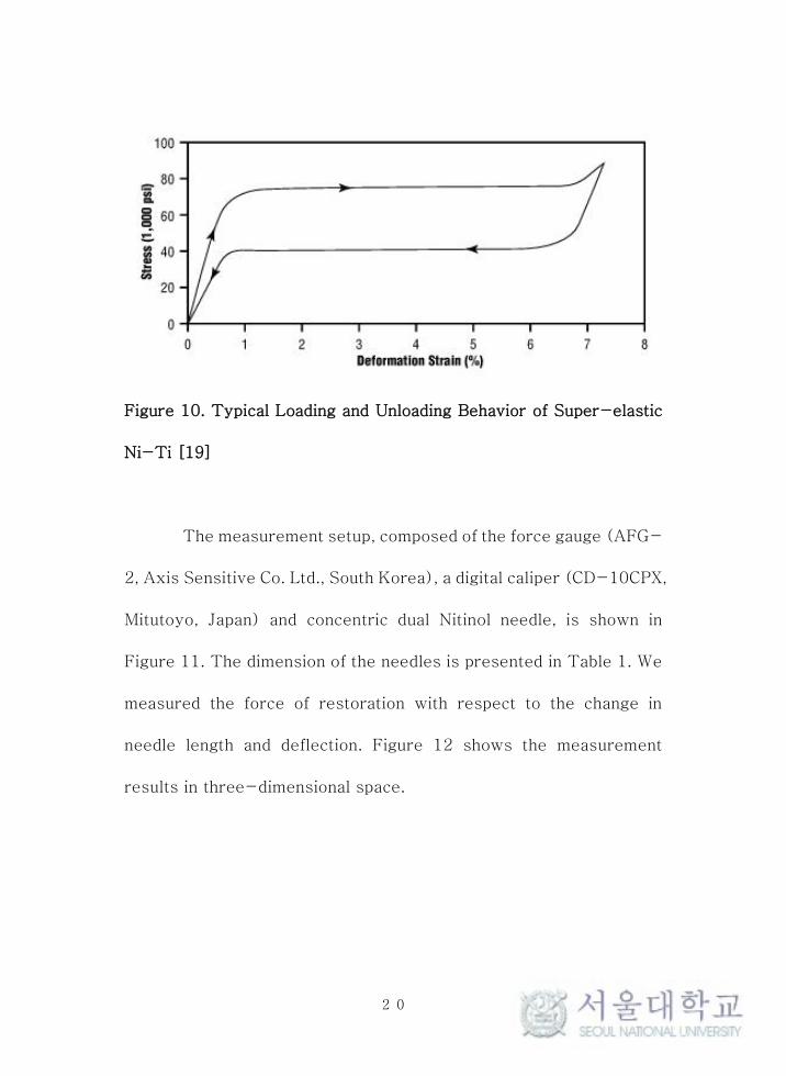
Bending stiffness is one of the material’s unique properties
in equation (19). Figure 10 shows the typical loading and unloading
behavior of a super-elastic Nitinol tube. The linear elastic behavior
is shown and bending stiffness 𝑘𝑏 can be measured within the range
shows linear elastic behavior under particular deformation. However,
the bending stiffness also changes the length from the fixed end to
the point of application. Thus, characterizing the bending stiffness
with respect to the length of the needle is necessary to acquire the
bending stiffness at an arbitrary pivot point.
20
Figure 10. Typical Loading and Unloading Behavior of Super-elastic
Ni-Ti [19]
The measurement setup, composed of the force gauge (AFG-
2, Axis Sensitive Co. Ltd., South Korea), a digital caliper (CD-10CPX,
Mitutoyo, Japan) and concentric dual Nitinol needle, is shown in
Figure 11. The dimension of the needles is presented in Table 1. We
measured the force of restoration with respect to the change in
needle length and deflection. Figure 12 shows the measurement
results in three-dimensional space.

21
Figure 11. Setup for measuring the needle bending stiffness
Table 1. Nitinol needle specification

22
Figure 12. A 3D visualization of the measurement results
The aim of this measurement is to determine the relationship
between the bending stiffness and length of needle; thus, sampling
the data sets within range showed linear behavior at several lengths
(30 mm, 35 mm, 40 mm, 45 mm, 50 mm) are used to acquire the
bending stiffness. (Figure 13)
23
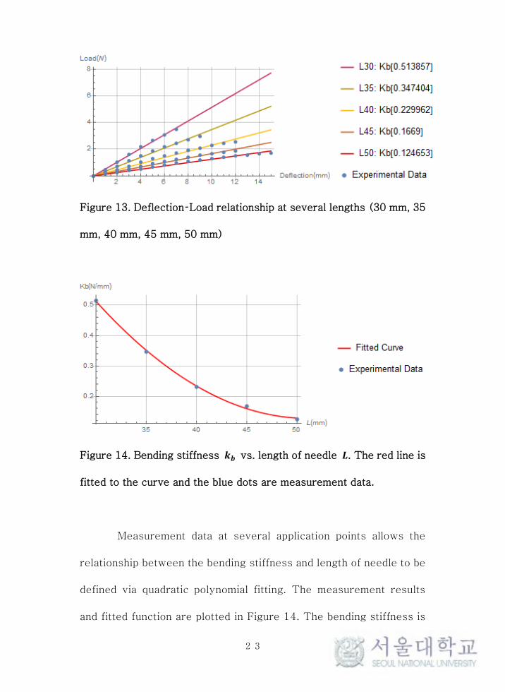
Figure 13. Deflection–Load relationship at several lengths (30 mm, 35
mm, 40 mm, 45 mm, 50 mm)
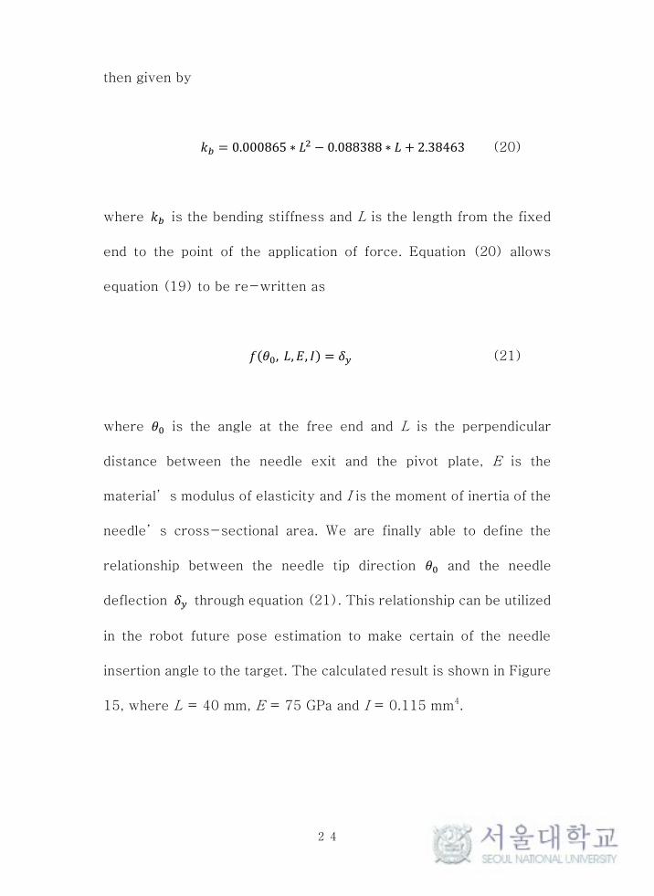
Figure 14. Bending stiffness 𝒌𝒃 vs. length of needle 𝑳. The red line is
fitted to the curve and the blue dots are measurement data.
Measurement data at several application points allows the
relationship between the bending stiffness and length of needle to be
defined via quadratic polynomial fitting. The measurement results
and fitted function are plotted in Figure 14. The bending stiffness is
24
then given by
𝑘𝑏 = 0.000865 ∗ 𝐿2 − 0.088388 ∗ 𝐿 + 2.38463 (20)
where 𝑘𝑏 is the bending stiffness and L is the length from the fixed
end to the point of the application of force. Equation (20) allows
equation (19) to be re-written as
𝑓(𝜃0, 𝐿, 𝐸, 𝐼) = 𝛿𝑦 (21)
where 𝜃0 is the angle at the free end and L is the perpendicular
distance between the needle exit and the pivot plate, E is the
material’s modulus of elasticity and I is the moment of inertia of the
needle’s cross-sectional area. We are finally able to define the
relationship between the needle tip direction 𝜃0 and the needle
deflection 𝛿𝑦 through equation (21). This relationship can be utilized
in the robot future pose estimation to make certain of the needle
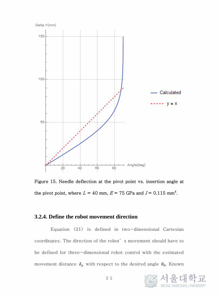
insertion angle to the target. The calculated result is shown in Figure
15, where L = 40 mm, E = 75 GPa and I = 0.115 mm4.
25
Figure 15. Needle deflection at the pivot point vs. insertion angle at
the pivot point, where L = 40 mm, E = 75 GPa and I = 0.115 mm4.
3.2.4. Define the robot movement direction
Equation (21) is defined in two-dimensional Cartesian
coordinates. The direction of the robot’s movement should have to
be defined for three-dimensional robot control with the estimated
movement distance 𝛿𝑦 with respect to the desired angle 𝜃0. Known
26
geometric information such as the target position and needle pivoting
breast plate’s hole position from registration allows the easy
definition of the plane of motion, and the robot movement direction
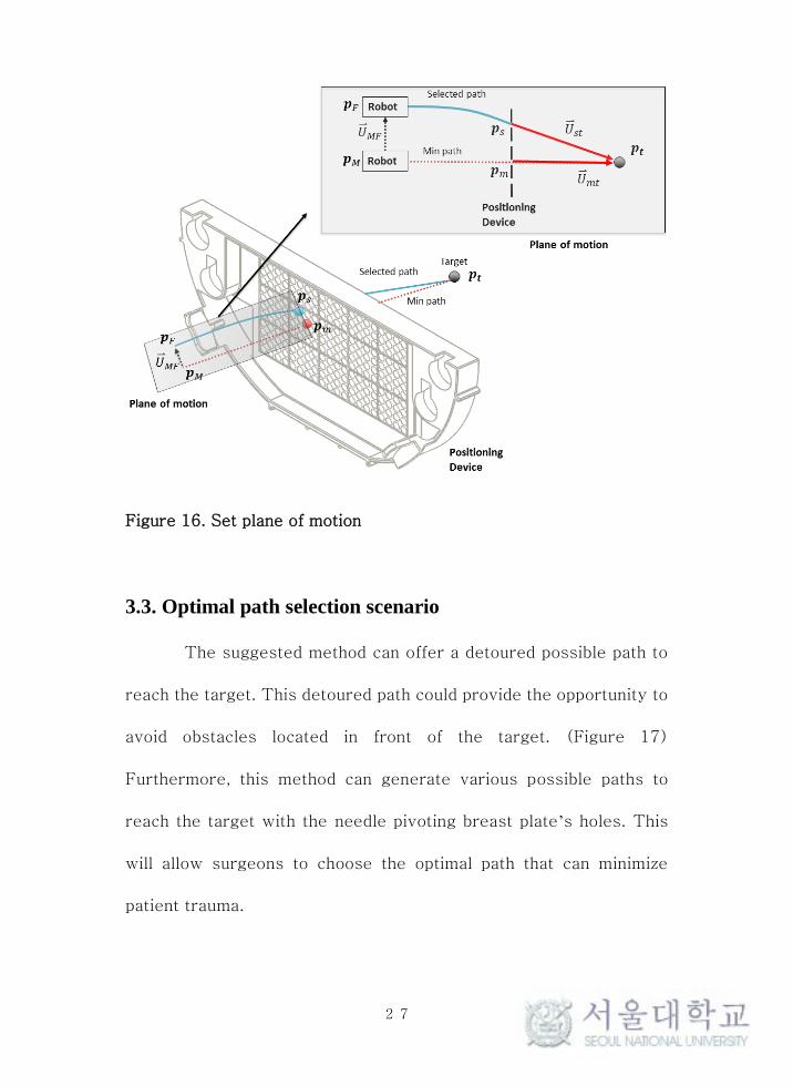
can be defined on this plane of motion. (Figure 16)
To be specific, directional vector 𝑈𝑚𝑡⃑⃑ ⃑⃑ ⃑⃑ ⃑ is acquired from
minimum distance hole position 𝒑𝑚 and target position 𝒑𝑡 . And
directional vector 𝑈𝑠𝑡⃑⃑⃑⃑⃑⃑ is also acquired from selected hole position 𝒑𝑠
and target position 𝒑𝑡. With these two directional vectors, specific
plane can be generated. We use this plane as the plane of motion that
robot movement direction for steering 𝑈𝑀𝐹⃑⃑ ⃑⃑ ⃑⃑ ⃑⃑ is generated. Such
constraint of robot motion allows us to find only one solution from
equation (21).
By all procedures mentioned in Section 3.2, robot position
control for needle steering can be successfully achieved. We utilized
the equation to determine the movement of the actuator 𝛿𝑦 to make
the desired needle path to the given pivot point to the target point.
Because the positions of the pivot point and the target point were
given, the angle 𝜃0 was given. And we knew L from the system
dimension and the coordinates of the markers on the robot and the
breast plate.
27
Figure 16. Set plane of motion
3.3. Optimal path selection scenario
The suggested method can offer a detoured possible path to
reach the target. This detoured path could provide the opportunity to
avoid obstacles located in front of the target. (Figure 17)
Furthermore, this method can generate various possible paths to
reach the target with the needle pivoting breast plate’s holes. This
will allow surgeons to choose the optimal path that can minimize
patient trauma.

28
Figure 17. Estimated needle path to reach the target
Figure 18. Optimal path selection scenario

29
The optimal path selection is comprised of the following steps:
(1) Find the hole the minimum distance from the target; (2) Suggest
neighbor holes to the minimum distance hole; (3) Suggest possible
paths to reach the target and validate the interruption; (4) The
surgeon chooses the optimal path from the MRI, which allows them
to avoid obstacles. (Figure 18.)
30
Chapter 4. Results
We present the experimental setup used to steer the flexible
needle with the proposed method and the targeting results in a
laboratory environment in this section.
4.1. In vitro Test
4.1.1 Experiment setup
The experimental setup is composed of an MR-guided breast
needle intervention robot and an infrared (IR) tracking camera (V120
Slim, OptiTrack, US). In total, eight IR tracking cameras are used in
the experiment to track the positions of the target and needle end.
(Figure 19) MR fiducial markers to trace the robot position in MRI
were also replaced with IR active markers (MTE8600M2, Marktech
Optoelctronics, Latham, NY, USA).
An experiment is used to evaluate the needle steering
algorithm that is comprised of the following steps: (1) Set the target
position; (2) Position the needle tip at the target position; (3)
Measure the needle tip position; (4) Compute the targeting error. In
total, 45 different paths to the same target position are conducted.
All targeting process are conducted via open loop control. The
targeting error is computed as follows
31
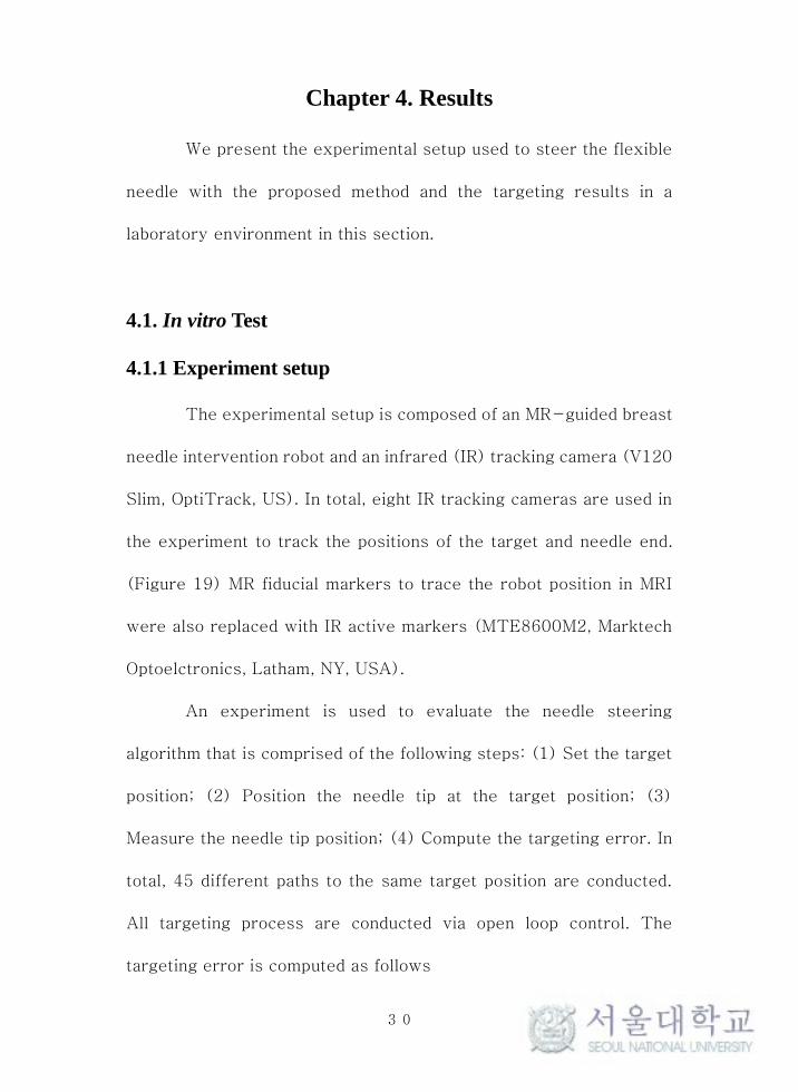
𝑇𝑎𝑟𝑔𝑒𝑡𝑖𝑛𝑔 𝐸𝑟𝑟𝑜𝑟 = ‖𝒑𝑡𝑎𝑟𝑔𝑒𝑡 − 𝒑𝑡𝑖𝑝‖ (9)
𝒑𝑡𝑎𝑟𝑔𝑒𝑡 is the target position and 𝒑𝑡𝑖𝑝 is the needle tip position.
Figure 19. Experimental setup using IR tracking cameras

32
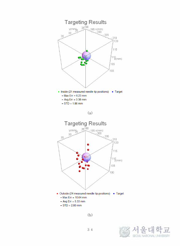
4.1.2 Target error
The selected holes of the needle pivoting breast plate are
shown in Figure 20. We categorized the results as either inside or
outside based on its insertion angle.
Figure 20. Selected holes for the experiment
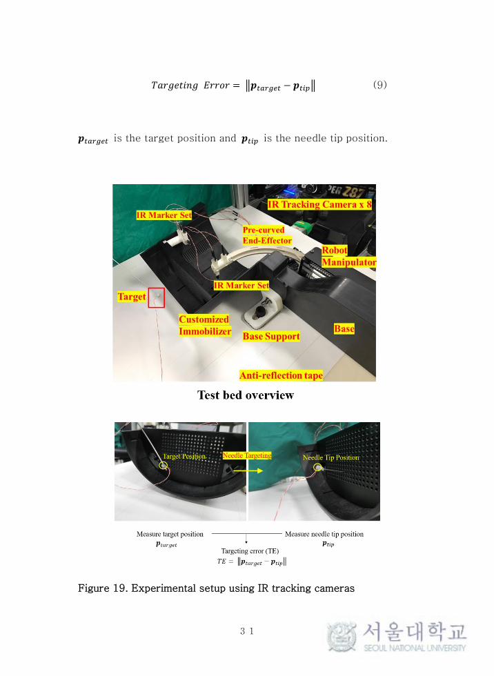
The average targeting error and standard deviation of the 45
samples is 4.42 ± 2.58 mm. In the 21 inside paths that have a
relatively small insertion angle (less than 10°), the average
targeting error and standard deviation was 3.38 ± 1.86 mm, and in
the 24 outside paths that have a relatively large insertion angle
(greater than 10°), the average targeting error and standard
deviation is 5.33 ± 2.80 mm. (Figure 21 and Table 2) Figure 22 is a
33
3D visualization of the targeting results.
Figure 21. Box whisker chart of the targeting error
In vitro Test Targeting Error (mm)
21 measured
(< 10˚ insertion angle) 3.38 ± 1.86
24 measured
(>10˚ insertion angle) 5.33 ± 2.80
45 measured (Total) 4.42 ± 2.58
Table 2. Targeting error results
34
(a)
(b)

35
(c)
Figure 22. A 3D visualization of the targeting result; (a) Inside (21
measured needle positions, Insertion angle <10°); (b) Outside (24
measured needle positions, Insertion angle >10°); (c) Total (45
samples)

36
Chapter 5. Discussions
The aim of targeting error was less than 2 mm in vitro tests.
Unfortunately, the experimental results did not fulfill this goal. Some
cases showed a relatively large targeting error of up to 10.64mm.
Generally, experimental results show that the targeting error
increased in proportion to the insertion angle.
The error can be induced from two factors: (1) the numeric
error from the possible non-linear behavior of the needle; (2) the
clearance margin of the pivot holes.
The first possible cause of this error is the non-linear
behavior of the Nitinol needle, since Nitinol shows non-linear
behavior above a certain deformation strain. The large insertion angle
meant that the Nitinol needle had a large deflection. When the Nitinol
needle was deflected with a large insertion angle, it was possible that
it showed non-linear behavior. This non-linear characteristic of the
material could induce errors in the needle deflection estimation model
based on the behavior of the linear elastic materials. Thus, we need
to determine the exact range in which the Nitinol needle works with
linear elastic behavior to reduce this error.
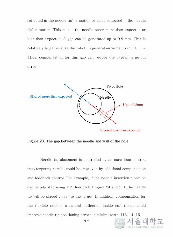
The other reason for the error is the gap between the needle
and the wall of the pivot hole. (Figure 23) The gap between the
needle and wall can cause that the robot’s initial movements are not
37
reflected in the needle tip’s motion or early reflected in the needle
tip’s motion. This makes the needle steer more than expected or
less than expected. A gap can be generated up to 0.8 mm. This is
relatively large because the robot’s general movement is 5–10 mm.
Thus, compensating for this gap can reduce the overall targeting
error.
Figure 23. The gap between the needle and wall of the hole
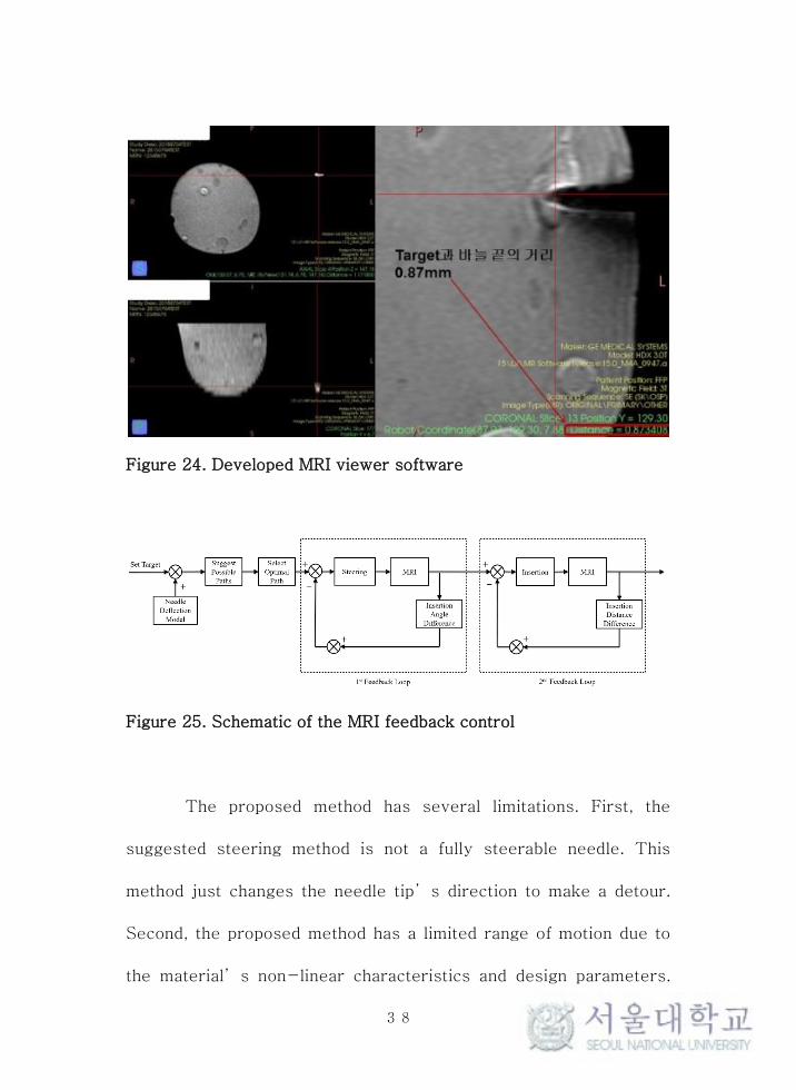
Needle tip placement is controlled by an open loop control,
thus targeting results could be improved by additional compensation
and feedback control. For example, if the needle insertion direction
can be adjusted using MRI feedback (Figure 24 and 25), the needle
tip will be placed closer to the target. In addition, compensation for
the flexible needle’s natural deflection inside soft tissue could
improve needle tip positioning errors in clinical tests. [13, 14, 15]
38
Figure 24. Developed MRI viewer software
Figure 25. Schematic of the MRI feedback control
The proposed method has several limitations. First, the
suggested steering method is not a fully steerable needle. This
method just changes the needle tip’s direction to make a detour.
Second, the proposed method has a limited range of motion due to
the material’s non-linear characteristics and design parameters.

39
However, the proposed method has the following advantages. This
could make various routes to reach the target and minimize the
system size increase. In addition, this could be applied to other
robotic systems with limited DOFs. These advantages mean that the
suggested method will have a positive effect on other robotic breast
needle intervention systems.

40
Bibliography
[1] American Cancer Society (2016) Cancer facts & figures
2016. American Cancer Society, Atlanta
[2] Abolhassani, Niki, Rajni Patel, and Mehrdad Moallem.
"Needle insertion into soft tissue: A survey." Medical engineering &
physics 29.4 (2007): 413-431.
[3] Podder, T., et al. "Effects of tip geometry of surgical
needles: an assessment of force and deflection." IFMBE Proc. Vol.
11. No. 1. 2005.
[4] Lehman, Constance D., et al. "MRI evaluation of the
contralateral breast in women with recently diagnosed breast
cancer." New England Journal of Medicine 356.13 (2007): 1295-
1303.
[5] Kuhl, Christiane K., et al. "MRI for diagnosis of pure ductal
carcinoma in situ: a prospective observational study." The Lancet
370.9586 (2007): 485-492.
[6] Yang, Bo, et al. "Design and implementation of a
pneumatically-actuated robot for breast biopsy under continuous
MRI." Robotics and Automation (ICRA), 2011 IEEE International
Conference on. IEEE, 2011.
[7] Yang, Bo, et al. "Design, development, and evaluation of a

41
master-slave surgical system for breast biopsy under continuous
MRI." The International journal of robotics research (2013):
0278364913500365.
[8] Reed, Kyle B., et al. "Robot-assisted needle steering." IEEE
Robotics & Automation Magazine 18.4 (2011): 35-46.
[9] Swaney, Philip J., et al. "A flexure-based steerable needle:
high curvature with reduced tissue damage." IEEE Transactions on
Biomedical Engineering 60.4 (2013): 906-909.
[10] Konh, Bardia, et al. "Design, Development and Evaluation of
a Two Way Actuated Steerable Needle." ASME 2015 Conference on
Smart Materials, Adaptive Structures and Intelligent Systems.
American Society of Mechanical Engineers, 2015.
[11) Ryu, Seok Chang, et al. "Design of an optically controlled
MR-compatible active needle." IEEE Transactions on Robotics 31.1
(2015): 1-11.
[12] Shahriari, Navid, et al. "Steering an actuated-tip needle in
biological tissue: fusing FBG-sensor data and ultrasound images."
(2016).
[13] Webster, Robert J., et al. "Nonholonomic modeling of needle
steering." The International Journal of Robotics Research 25.5-6
(2006): 509-525.
[14] Cowan, Noah J., et al. "Robotic needle steering: Design,

42
modeling, planning, and image guidance." Surgical Robotics.
Springer US, 2011. 557-582.
[15] Moreira, Pedro, and Sarthak Misra. "Biomechanics-based
curvature estimation for ultrasound-guided flexible needle steering
in biological tissues." Annals of biomedical engineering 43.8 (2015):
1716-1726.
[16] Samuel B. Park, J. Kim, K. Lim, C. Yoon, D. Kim, H. Kang,
and Yung-Ho Jo, “A Magnetic Resonance Image-Guided Breast
Needle Intervention Robot System: Overview and Design
Consideration,” Int. Journal of Computer Assisted Radiology and
Surgery, (Submitted for Review)
[17] Ang, Marcel H., Wang Wei, and Low Teck-Seng. "On the
estimation of the large deflection of a cantilever beam." Industrial
Electronics, Control, and Instrumentation, 1993. Proceedings of the
IECON'93., International Conference on. IEEE, 1993.
[18] Howell, Larry L. Compliant mechanisms. John Wiley &
Sons, 2001.
[19] Johnson Matthey Medical Components,
http://jmmedical.com/
43
초 록
MR 유도 바늘 중재시술은 유방의 진단과 치료에서 가장
일반적으로 사용되는 방법이다. 바늘 끝단의 잘못된 도달은 치료의
실패나 오진을 유발할 수 있기 때문에 바늘 끝단의 정확한
목표지점으로의 도달은 시술의 성공여부에 있어 중요하다. 또한, 높은
정밀도를 지니는 바늘 스티어링 로봇 시스템의 개발은 목표지점 앞에
존재하는 중요한 기관들을 회피하여 환자의 후유증을 최소화하기 위해
필요하다. 하지만 강한 자기장의 영향과 협소한 MRI 장비의 보어
크기로 인하여, 고자유도의 로봇 시스템을 구성하는 것은 쉽지 않다. 본
연구는 MR 유도 유방 바늘 중재시술에 효과적으로 활용될 수 있는
MRI 장비의 보어 안의 한정된 공간 안에서 시스템의 크기 증가를
최소화하며 바늘을 스티어링 할 수 있는 전략을 제안한다. 공간적
제약과 병변 앞의 위험 구조물을 회피하기 위한 바늘 끝단 방향의
변화는 피봇 움직임을 통해 수행하였다. 바늘 끝단의 자유도를 증가
시키기 위한 바늘 피봇팅 가슴 압착 기구와 피봇된 플렉시블 Nitinol
바늘에서 발생하는 변형을 예측 모델을 고안하였다. 이 예측 모델은
보의 대변형 이론에 근거하였으며, 로봇의 제어에 활용된다. 적외선
위치추적 카메라를 사용한 실험 환경에서 개루프 제어를 통한 바늘의
위치 도달 실험을 수행하여 제안된 방법의 실효성을 검증하였다.
실험으로 측정된 평균 위치 도달 오차와 표준편차는 4.42 ± 2.58 mm
이다.

44
주요어: MR 유도 유방 바늘 중재시술 로봇, 바늘 피보팅 가슴 압착
플레이트, 바늘 스티어링, 초탄성 플렉시블 바늘, 바늘 변형 예측, 보의
대변형 이론
학 번: 2013-23084