Embed Size (px)
Citation preview

저 시-비 리- 경 지 2.0 한민
는 아래 조건 르는 경 에 한하여 게
l 저 물 복제, 포, 전송, 전시, 공연 송할 수 습니다.
다 과 같 조건 라야 합니다:
l 하는, 저 물 나 포 경 , 저 물에 적 된 허락조건 명확하게 나타내어야 합니다.
l 저 터 허가를 면 러한 조건들 적 되지 않습니다.
저 에 른 리는 내 에 하여 향 지 않습니다.
것 허락규약(Legal Code) 해하 쉽게 약한 것 니다.
Disclaimer
저 시. 하는 원저 를 시하여야 합니다.
비 리. 하는 저 물 리 목적 할 수 없습니다.
경 지. 하는 저 물 개 , 형 또는 가공할 수 없습니다.

Influence of elastic modulus of periodontal ligament
on the centers of rotation of incisors
: Finite element analysis
Hyesun Kim
The Graduate School
Yonsei University
Department of Dentistry
Influence of elastic modulus of periodontal ligament
on the centers of rotation of incisors
: Finite element analysis
The Dissertation Thesis
Submitted to the Department of Dentistry
and the Graduate School of Yonsei University
in partial fulfillment of the
requirements for the degree of
Doctor of philosophy of Dental Science
Hyesun Kim
June 2016

감사의 글
부족하기만 한 저를 지도해 주신 교수님들의 크신 가르침으로 이 논
문을 완성할 수 있었습니다. 논문 구상부터 완성까지 많은 배려와 세심
한 지도를 베풀어 주신 이기준 지도 교수님께 진심으로 감사 드립니다.
많은 업무로 바쁘신 중에도 귀한 시간을 내 주시어 부족한 논문에 대한
조언을 주신 백형선 교수님, 유형석 교수님, 최광철 원장님, 조영수 박
사님께 깊이 감사 드립니다. 또한, 교정학을 공부할 수 있도록 기회를
주신 박영철 교수님, 황충주 교수님, 김경호 교수님, 정주령 교수님, 차
정렬 교수님, 최윤정 교수님, 최성환 교수님께 깊이 감사 드립니다.
논문이 나오기까지 격려와 조언을 주신 연세대학교 교정과 의국
선생님들과 대학원 선생님들께 깊은 감사의 마음을 전합니다.
항상 크신 지혜와 사랑으로 바른 길로 이끌어 주시는 아버님, 어머님,
늘 끝없는 사랑과 정성으로 응원해 주시는 아버지, 어머니께 깊은
감사의 마음을 올립니다. 언제나 곁에서 조언하고 감싸주어 인생의
든든한 동반자가 되어 주는 남편 윤병선 선생님께 존경과 사랑의
마음을 전하며, 늘 의젓하게 자신의 일을 대견하게 해 나가는 두 딸,
준희와 성은이에게 사랑과 고마움의 마음을 전합니다.
2016 년 6 월
저자 씀
i
Table of Contents
List of figures .............................................................................................................ii
List of tables ............................................................................................................. iii
Abstract (English) .....................................................................................................iv
I. Introduction ............................................................................................................1
II. Materials and methods ..........................................................................................4
A. Construction of finite element models ........................................................4
B. Mechanical variables of the material properties ........................................4
C. Loading condition ..........................................................................................8
D. Calculation of center of rotation / center of resistance ............................9
III. Results ............................................................................................................... 11
IV. Discussion ......................................................................................................... 18
V. Conclusion ........................................................................................................... 21
References ............................................................................................................... 23
Abstract (Korean) ................................................................................................... 30
ii
List of Figures
Figure 1. Three dimensional finite element model ...............................................5
Figure 2. Modeling of the upper incisor .................................................................6
Figure 3. Model elements of upper incisors and surrounding tissue....................7
Figure 4. Force application at different occluso-gingival levels (㎜) ................8
Figure 5. Center of rotation ......................................................................................9
Figure 6. Vertical position of Crot of upper central incisors according to elastic
modulus of PDL at each force application level (㎜) ......................... 11
Figure 7. Change of horizontal & vertical position of Crot of upper central
incisors according to force application level (㎜) (E – 71.5 MPa) ..... 12
Figure 8. Vertical position of Cres(㎜)of upper central incisors according to E
................................................................................................................. 13
Figure 9. Location of the center of rotations in the X-Y plane in accordance
with various E ....................................................................................... 14
Figure 10. Stress distribution pattern in the PDL after application of retraction
force on upper central incisors at Cres ............................................ 15
Figure 11. The characteristics of teeth movement according to E in accordance
with different force application levels. ............................................. 17
iii
List of Tables
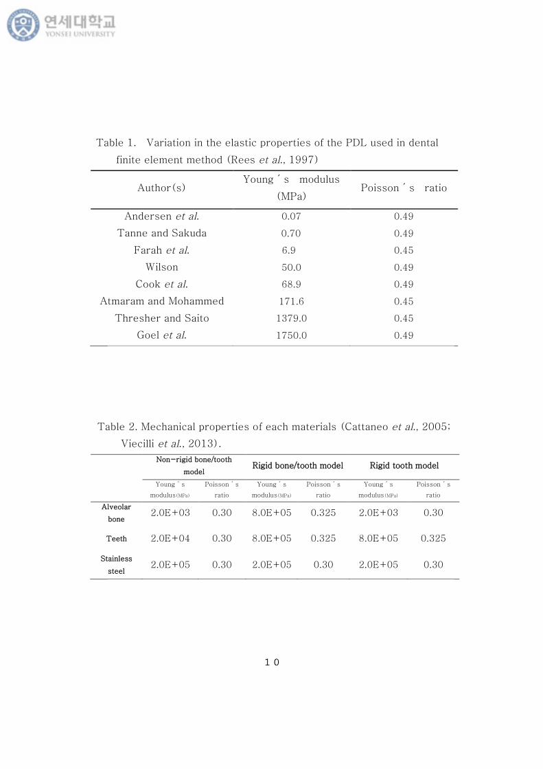
Table 1. Variation in the elastic properties of the PDL used in dental finite
element method ...................................................................................... 10
Table 2. Mechanical properties of each materials ............................................. 10
Table 3. Changes in initial tooth displacements in varying degrees of E ........ 16

iv
ABSTRACT
Influence of elastic modulus of periodontal ligament
on the centers of rotation of incisors
: Finite element analysis
Hyesun Kim
Department of Dentistry, Graduate School, Yonsei University
(Directed by Professor Kee Joon Lee, D.D.S., M.S.D., Ph.D.)
Consideration of the physical properties of the periodontium is important in
diagnosis and treatment planning of orthodontic treatment. Moreover,
periodontal ligament (PDL) is the most important tissue in proceeding of tooth
movement under orthodontic loading. The elastic modulus of periodontal
ligament (E) used in previous studies has quite wide range of value from 0.07 to
1,750 MPa.
The objective of this study was to measure the changes of the centers of
rotation (Crot) of upper central incisors and evaluate the influence of physical
v
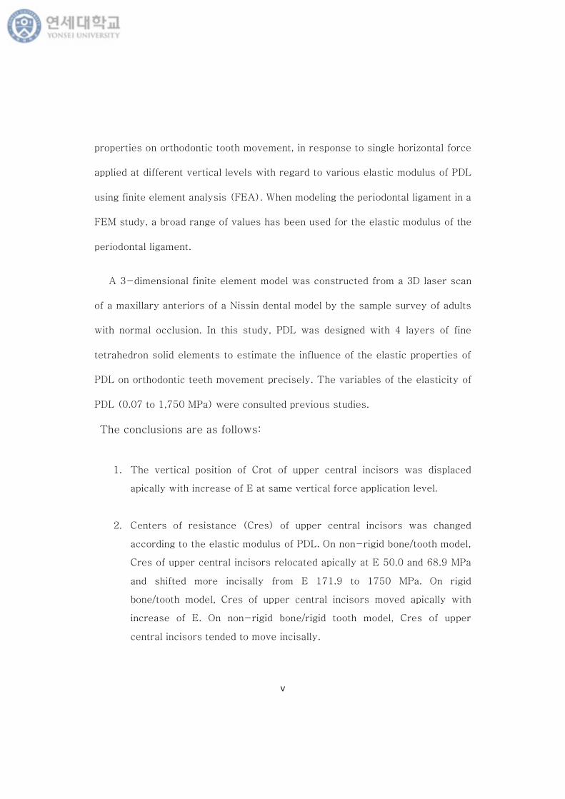
properties on orthodontic tooth movement, in response to single horizontal force
applied at different vertical levels with regard to various elastic modulus of PDL
using finite element analysis (FEA). When modeling the periodontal ligament in a
FEM study, a broad range of values has been used for the elastic modulus of the
periodontal ligament.
A 3-dimensional finite element model was constructed from a 3D laser scan
of a maxillary anteriors of a Nissin dental model by the sample survey of adults
with normal occlusion. In this study, PDL was designed with 4 layers of fine
tetrahedron solid elements to estimate the influence of the elastic properties of
PDL on orthodontic teeth movement precisely. The variables of the elasticity of
PDL (0.07 to 1,750 MPa) were consulted previous studies.
The conclusions are as follows:
1. The vertical position of Crot of upper central incisors was displaced
apically with increase of E at same vertical force application level.
2. Centers of resistance (Cres) of upper central incisors was changed
according to the elastic modulus of PDL. On non-rigid bone/tooth model,
Cres of upper central incisors relocated apically at E 50.0 and 68.9 MPa
and shifted more incisally from E 171.9 to 1750 MPa. On rigid
bone/tooth model, Cres of upper central incisors moved apically with
increase of E. On non-rigid bone/rigid tooth model, Cres of upper
central incisors tended to move incisally.

vi
3. The 'functional axes' (traces of the measured Crot) of the upper central
incisors were formulized in accordance with various E. The Crot
distributed on a line under given E in relation to the horizontal forces
applied to the various vertical level. The different linear equations
could be evaluated with coefficients in accordance with various E, which
slopes turn counterclockwise direction gradually with increase of E.
The absolute quantity of displacement and the tendency of rotation of teeth
used to decrease with increased E, when compared the characteristics of teeth
movement according to E. Consideration of the physical properties of the PDL
might be an important factor in diagnosis and treatment planning of orthodontic
treatment.
Key words : elastic modulus of PDL(E) , center of rotation , center of resistance,
functional axis, finite element analysis

1
Influence of elastic modulus of periodontal ligament
on the centers of rotation of incisors
: Finite element analysis
Hyesun Kim
Department of Dentistry, Graduate School, Yonsei University
(Directed by Professor Kee Joon Lee, D.D.S., M.S.D., Ph.D.)
I. Introduction
The center of rotation (Crot) is considered as an important point for tooth
movement. The position of Crot determines the type of tooth movement such as
crown tipping, translation, root movement, and gives us a clue for the equivalent
force and torque need for each force system. The location of center of rotation
is changed with the vertical position of force applied to the teeth.
Many models and methods have been developed to study the relationship
between the location of force, the center of resistance (Cres) and the center of
rotation (Crot) (Yettram AL et al., 1977; Williams KR et al., 1986). In
orthodontics, FEM has been used successfully to model the application of forces
to tooth systems (Selna LG et al., 1975; Takahashi N et al., 1980; Atmaram et
2
al., 1981; Williams KR et al., 1984; Kim et al., 1991).
The PDL is soft, richly vascular and cellular connective tissue that joins the
root cementum to the surrounding alveolar bone proper. The ligament is
approximately 0.25 ㎜ ±50% wide and composed principally of collagen fibers
that run in various directions between the root surface and supporting alveolar
bone, functions as a shock absorber during occlusal load. Magnitude and
direction of orthodontic loads should be changed considering individual
difference in elasticity of PDL (Lindhe et al., 1989; Coolidge E., 1937).
Knowledge of the physical properties of the periodontal ligament would be
useful to help elucidate the role of the ligament in absorbing occlusal load and
to increase understanding of tooth movement under orthodontic loading. Little
information is available about the physical properties of the ligament in
isolation due to problems of obtaining pure samples. Most studies have used a
value of 0.4-0.49 for Poisson´s ratio. However, previous studies have
reported quite different values of wide range of elastic modulus of the ligament
from 0.01 to 1,750 MPa ( Picton et al., 1963; Tanne et al., 1987; Rees et
al.,1997) (Table 1).
Choy et al. (2006) investigated the changes in the initial center of rotation
(Crot) of upper anterior teeth in response to a horizontal load, and recorded a
linear functional axis (a trace of the measured Crot), maintained an angle of
14.5 °to the vertical axis of the anterior segment. Choy et al. (2006) discussed

3
factors affecting the angle of the functional axis, including an inclination of the
roots and physical properties of the PDL.
The objective of this study was to measure the changes of the Crot of the
anterior segments, in response to single horizontal force applied at different
occluso-gingival levels with regard to various elastic modulus of PDL (E) using
FEM. When modeling the periodontal ligament in a FEM study, a wide range of
values has been used for the elastic modulus of the PDL (E) (Table 1).
4
II. Materials and methods
A. Construction of finite element models
A finite element model was constructed from a 3D laser scan of the maxillary
anteriors of a Nissin dental model by the sample survey of adults with normal
occlusion (Model-i12D-400G, Nissin Dental Products, Kyoto, Japan). The
thickness of the PDL was assumed to be uniform (0.25 ㎜) and even around the
root surface. The morphology of the alveolar bone were modeled 1㎜ above
cemento-enamel junction following curvature of the CEJ. Maxillary anteriors are
joined as rigid unit, and force vector was applied to a vertical extension
perpendicular to the occlusal plane in the midsagittal plane between both upper
central incisors.
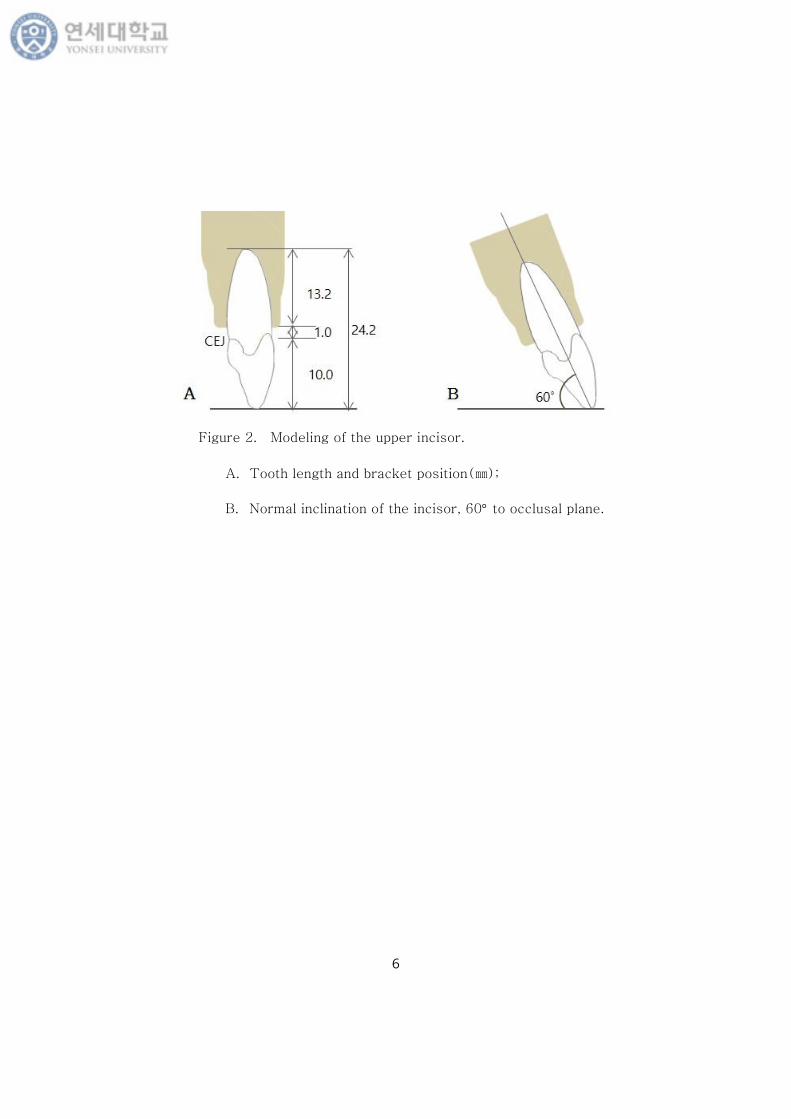
Tooth length of upper central incisor measured from incisal edge to root apex,
was 24.2 ㎜ : The crown was 11㎜ from incisal edge to labial CEJ and the root
13.2mm. The long axis of each incisor model was inclined 60° facially from the
occlusal plane. A standard coordination system was constructed with the x-axis,
y-axis, and z-axis (Figure 1, 2). The teeth, alveolar bone, and PDL were all
constructed using fine tetrahedron solid elements, and were all assumed to be
isoparametric and homogeneous linear elastic bodies. In this study, PDL was
constructed with 4 layers of elements with fine tetrahedron solid nodes to
simulate the elasticity of PDL (Figure 3).
B. Mechanical variables of the material properties.
The variables of the elasticity of PDL were consulted previous studies (Young’
s modulus and Poisson’s ratio)(Table 1)(Andersen et al., 1991; Tanne et al.,
1987; Farah et al., 1989; Wilson, 1991; Cook et al., 1982; Thresher et al., 1973;
5
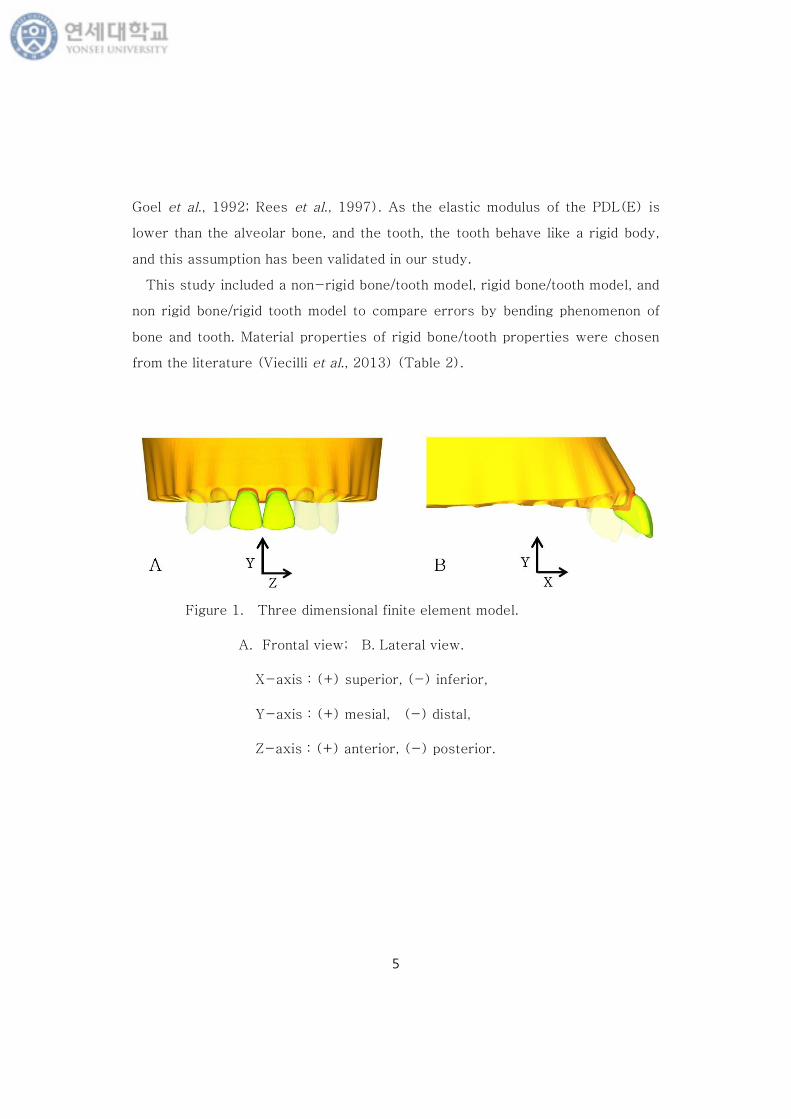
Goel et al., 1992; Rees et al., 1997). As the elastic modulus of the PDL(E) is
lower than the alveolar bone, and the tooth, the tooth behave like a rigid body,
and this assumption has been validated in our study.
This study included a non-rigid bone/tooth model, rigid bone/tooth model, and
non rigid bone/rigid tooth model to compare errors by bending phenomenon of
bone and tooth. Material properties of rigid bone/tooth properties were chosen
from the literature (Viecilli et al., 2013) (Table 2).
Figure 1. Three dimensional finite element model.
A. Frontal view; B. Lateral view.
X-axis : (+) superior, (-) inferior,
Y-axis : (+) mesial, (-) distal,
Z-axis : (+) anterior, (-) posterior.
6
Figure 2. Modeling of the upper incisor.
A. Tooth length and bracket position(㎜);
B. Normal inclination of the incisor, 60°to occlusal plane.

7
Figure 3. Model elements of upper incisors and surrounding tissue.
A. The elements of PDL constructed with 4 fine tetrahedron solid nodes;
B. The elements of PDL and surrounding bone;
C. The elements of upper incisors and surrounding tissue.

8
C. Loading condition
A single force vector (200 g) was applied to the vertical extension of the
splint in the midsagittal plane of both upper central incisors at different vertical
levels. It was assumed that there was no play between the teeth and the vertical
extension of the splint. A horizon force was given from the 0.0 ㎜ position(level
of incisal tip of the central incisors) to the 25.0㎜ position with an interval of 5.0
㎜. Around predicted point as center of resistance, force was applied with an
interval of 0.01 ㎜. The midpoints of incisal edges{(X1 , Y1 ), (X1´,Y1´)} and
root apices{(X2 ,Y2 ),(X2´,Y2´)} of central incisors were used as landmarks
for the assessment of center of rotation, using the finite element analysis
program(ANSYS Ver. 12.1, Swanson Analysis System, Canonburg, PA ) (Fig.4).
Figure 4. Force application at different occluso-gingival levels (㎜)
: A horizon force was given from the 0.0 ㎜ position(level of incisal
tip of the central incisors) to the 25.0 ㎜ position with an interval
of 5.0 ㎜.
㎜

9
D. Calculation of center of rotation / center of resistance
Centers of rotation were calculated using following formulae.
Then, centers of resistance could be estimated
by the translation tests and error analyses.
X Crot `=((Y1´-Y1)×(Y2´-Y2)×((Y2´+Y2)-(Y1´+Y1))+(X2´+X2)×(X2´-X2)×(Y1´-Y1)-(X1´+X1)×(X1´-X1)×(Y2´-Y2))
2×((X2´-X2)×(Y1´-Y1)-(X1´-X1)×(Y2´-Y2))
Y Crot =
((X1´-X1)×(X2´-X2)×((X1´+X1)-(X2´+X2))+(X2´-X2)×(Y1´-Y1)×(Y1´+Y1)-(X1´-X1)×(Y2´+Y2)×(Y2´-Y2))
2×((X2´-X2)×(Y1´-Y1)-(X1´-X1)×(Y2´-Y2))
Figure 5. Center of rotation
10
Table 1. Variation in the elastic properties of the PDL used in dental
finite element method (Rees et al., 1997)
Author(s)Young´s modulus
(MPa)Poisson´s ratio
Andersen et al. 0.07 0.49
Tanne and Sakuda 0.70 0.49
Farah et al. 6.9 0.45
Wilson 50.0 0.49
Cook et al. 68.9 0.49
Atmaram and Mohammed 171.6 0.45
Thresher and Saito 1379.0 0.45
Goel et al. 1750.0 0.49
Table 2. Mechanical properties of each materials (Cattaneo et al., 2005;
Viecilli et al., 2013).
Non-rigid bone/tooth
modelRigid bone/tooth model Rigid tooth model
Young´s
modulus(MPa)
Poisson´s
ratio
Young´s
modulus(MPa)
Poisson´s
ratio
Young´s
modulus(MPa)
Poisson´s
ratio
Alveolar
bone2.0E+03 0.30 8.0E+05 0.325 2.0E+03 0.30
Teeth 2.0E+04 0.30 8.0E+05 0.325 8.0E+05 0.325
Stainless
steel2.0E+05 0.30 2.0E+05 0.30 2.0E+05 0.30
11
III . Results
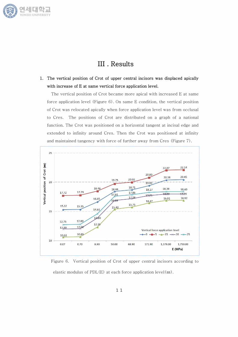
1. The vertical position of Crot of upper central incisors was displaced apically
with increase of E at same vertical force application level.
The vertical position of Crot became more apical with increased E at same
force application level (Figure 6). On same E condition, the vertical position
of Crot was relocated apically when force application level was from occlusal
to Cres. The positions of Crot are distributed on a graph of a national
function. The Crot was positioned on a horizontal tangent at incisal edge and
extended to infinity around Cres. Then the Crot was positioned at infinity
and maintained tangency with force of further away from Cres (Figure 7).
Figure 6. Vertical position of Crot of upper central incisors according to
elastic modulus of PDL(E) at each force application level(㎜).

12
Figure 7. Change of horizontal & vertical position of Crot of upper central
incisors according to force application level(㎜)(E – 71.5 MPa).
13
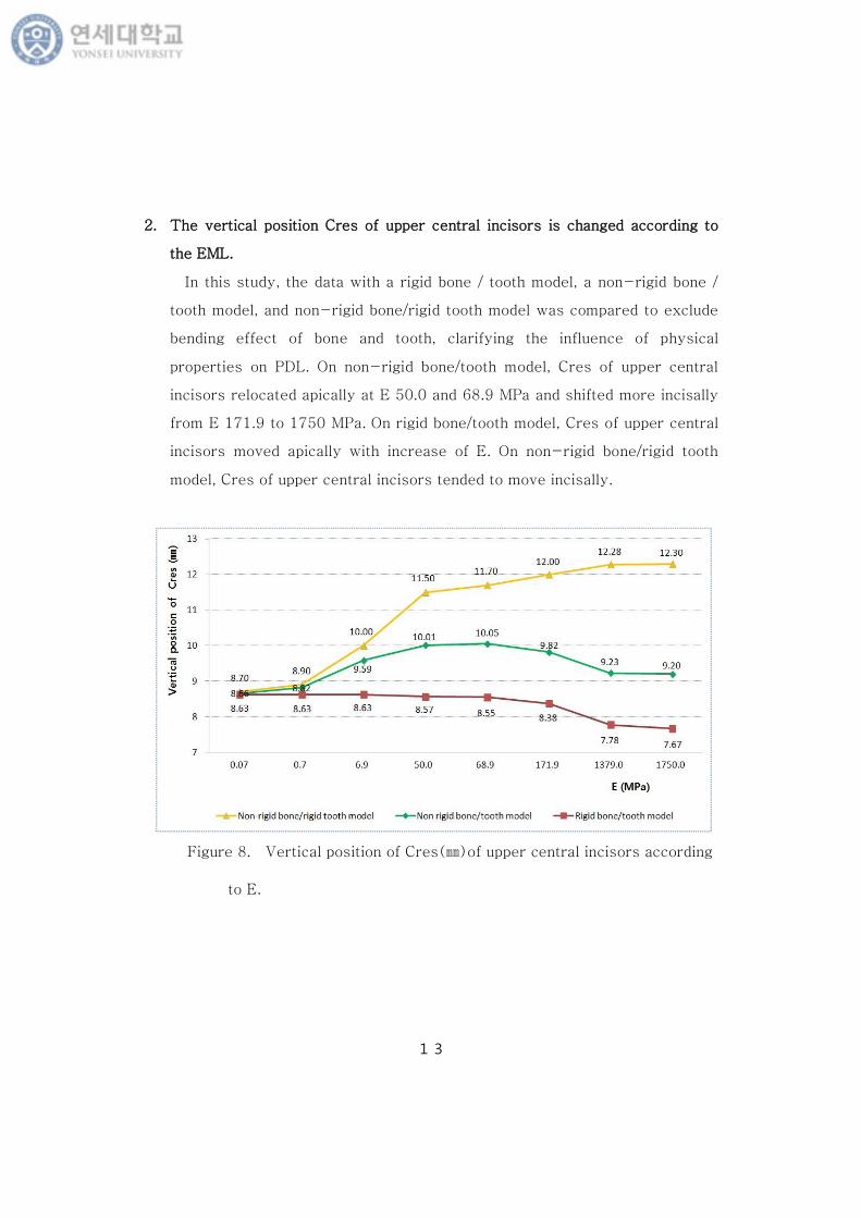
2. The vertical position Cres of upper central incisors is changed according to
the EML.
In this study, the data with a rigid bone / tooth model, a non-rigid bone /
tooth model, and non-rigid bone/rigid tooth model was compared to exclude
bending effect of bone and tooth, clarifying the influence of physical
properties on PDL. On non-rigid bone/tooth model, Cres of upper central
incisors relocated apically at E 50.0 and 68.9 MPa and shifted more incisally
from E 171.9 to 1750 MPa. On rigid bone/tooth model, Cres of upper central
incisors moved apically with increase of E. On non-rigid bone/rigid tooth
model, Cres of upper central incisors tended to move incisally.
Figure 8. Vertical position of Cres(㎜)of upper central incisors according
to E.
14
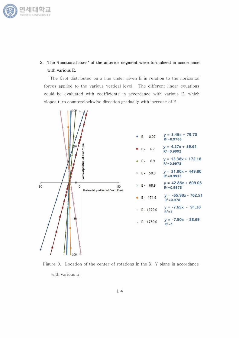
3. The ‘functional axes’ of the anterior segment were formulized in accordance
with various E.
The Crot distributed on a line under given E in relation to the horizontal
forces applied to the various vertical level. The different linear equations
could be evaluated with coefficients in accordance with various E, which
slopes turn counterclockwise direction gradually with increase of E.
Figure 9. Location of the center of rotations in the X-Y plane in accordance
with various E.

15
4. Minimum principal stress distribution is observed in the PDL of upper central
incisors with horizontal retraction force through the Cres.
There is uniformly increased stress on lingual periodontal membrane of
both central incisors, and uniformly decreased stress on labial, which mean
the close movement to translation of upper central incisors to lingual
direction.
Figure 10. Stress distribution pattern in the PDL after application of
retraction force on upper central incisors at Cres ( E - 68.9 MPa ,
vertical force application level - 10.05㎜ from occlusal plane).
A. Frontal view; B. Lingual view; C. Occlusal view.
A
BA
C
16
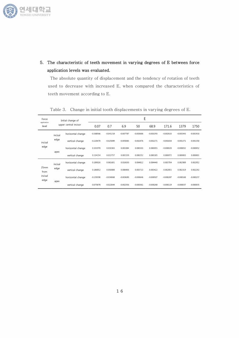
5. The characteristic of teeth movement in varying degrees of E between force
application levels was evaluated.
The absolute quantity of displacement and the tendency of rotation of teeth
used to decrease with increased E, when compared the characteristics of
teeth movement according to E.
Table 3. Change in initial tooth displacements in varying degrees of E.
Force
application
level
Initial change of
upper central incisor
E
0.07 0.7 6.9 50 68.9 171.6 1379 1750
incisal
edge
incisal
edge
horizontal change -0.368566 -0.041218 -0.007787 -0.003606 -0.003293 -0.002633 -0.001943 -0.001910
vertical change -0.220470 -0.025089 -0.005083 -0.002476 -0.002271 -0.001834 -0.001371 -0.001350
apex
horizontal change 0.101978 0.010365 0.001084 0.000103 0.000055 -0.000020 -0.000052 -0.000052
vertical change 0.134234 0.013737 0.001539 0.000252 0.000185 0.000072 0.000003 0.000001
25mm
from
incisal
edge
incisal
edge
horizontal change 0.189026 0.061601 0.010630 0.004812 0.004440 0.003704 0.002989 0.002952
vertical change 0.186852 0.050088 0.008406 0.003713 0.003422 0.002855 0.002319 0.002292
apex
horizontal change -0.159390 -0.034068 -0.003690 -0.000646 -0.000507 -0.000287 -0.000160 -0.000157
vertical change -0.075878 -0.022044 -0.002356 -0.000361 -0.000268 -0.000119 -0.000037 -0.000035
17
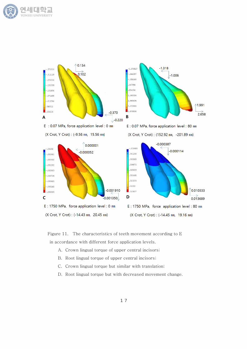
Figure 11. The characteristics of teeth movement according to E
in accordance with different force application levels.
A. Crown lingual torque of upper central incisors;
B. Root lingual torque of upper central incisors;
C. Crown lingual torque but similar with translation;
D. Root lingual torque but with decreased movement change.
C
BA
D

18
IV. Discussion
In this study the influence of elastic modulus of PDL was assessed on the
initial tooth movement of upper incisors. Differences in tooth displacement may
come from the change in the amount of displacement and the change of relations
between centers of rotation and centers of resistance (Ericsson et al., 1984;
Khoo et al., 1988; Tanne et al., 1991). The present study showed that
decreased initial tooth displacement and apically relocation of Cres and Crot with
increased resiliency of PDL. It does suggest that physical properties of PDL
should be considered in designing the equivalent force and torque system for
orthodontic teeth movement.
A lot of research has been reported about the location of the Cres.
Burstone(1966) described the Cres in a single rooted tooth at a point 40% of the
root length. Nikolai(1974) and Matsuura(1984) reported the location of Cres as
0.52 for the maxillary central incisor on the basis of a two-dimensional analysis.
Burstone and Pryputniewicz (1980) used a three-dimensional model and
established with a holographic technique the Cres at 0.31 the root length
measured from the alveolar crest. Tanne(1988) suggested the location of the
Cres at 0.24 the root length located farther coronally. The most relevant aspect
in the cited studies was the definition of a common Cres for the upper anterior
segment, having a position between 8.1-14.7 ㎜ apically to the incisal
edge(Vanden Bulcke et al., 1987; Melsen et al., 1990; Pedersen et al., 1991)
Choy et al.(2006) investigated the changes in the initial centers of rotation of
the upper six anterior teeth which roots coated with silicon in response to a
horizontal load, and obtained a linear´functional axis: y=3.861x + 53.153´.
They expected that there may be many factors affecting the angle of the
functional axis, including an inclination of the roots and the physical properties

19
of the PDL. The ‘functional axes’ of the anterior segment could be formularized
in accordance with various EML. The functional axes have positive slopes
passing from quadrant 1 to quadrant 3 with E 0.07, 0.7, 6.9, 50.0, 68.9, which
suggest that a small intrusive component of upper anterior segment could be
expected with lingual horizontal retraction force. By contrast, the functional
axes have negative slopes with E 171.9, 379.0, 1750.0, which may suggest
that a small extrusive component of upper anterior segment could be expected
with lingual horizontal retraction force. The´functional axis: y=3.861x +
53.153´obtained with silicon PDL by Choy et al.(2006) was similar with that
of E 0.07 and 0.7 .
To obviate confused estimation of results from bone and tooth bending, in this
study various type of model was planned with the rigid tooth / rigid bone model
and the rigid tooth / non-rigid bone model. The material properties of rigid tooth
/ bone model were assigned based on the data of Viecilli et al. with increased
elastic modulus of the tooth and bone to 800 GPa to improve resistance against
bending (Viecilli et al., 2013). On rigid bone/tooth model, Cres of upper central
incisors moved apically with increase of E, which represented the effect of
elastic properties of PDL on teeth movement independently. On non-rigid
bone/rigid tooth model, Cres of upper central incisors tended to move incisally
which implied bone bending covering the teeth movement. On non-rigid
bone/tooth model, Cres of upper central incisors relocated apically at E 50.0 and
68.9 MPa and shifted more incisally from E 171.9 to 1750 MPa with the mixed
result of bone and teeth bending to conceal the influence of E on tooth
movement alone.
When modeling the periodontal ligament in a finite element stress analysis
study, what physical property values to ascribe to this structure. A wide range
of values has been used for the elastic modulus of the ligament (Anderson et al.,
1991; Tanne et al., 1983; Farah et al., 1989; Takahashi et al., 1989, Wilson,

20
1991; Cook et al., 1982: Ko et al, 1996; Atmaram et al., 1981; Thresher et al.,
1973; Goel et al., 1992; Rees et al., 1997). This model was designed to compare
teeth displacement with variation of EML. Further experimental studies are
expected to reveal the exact characteristics the living PDL, accommodating
visco-elastic, non-linear properties and thickness variation. Also, objective
criteria should be established in diagnosis for physical condition of PDL.

21
V. Conclusion
From this study we measured Influence of elastic modulus of periodontal
ligament on the centers of rotation of incisors with regard to constant horizontal
force applied at different vertical levels using FEM. When modeling the
periodontal ligament in a FEM study, a wide range of values has been used for
the elastic modulus of the ligament.
The following findings were observed.
1. The vertical position of Crot of upper central incisors was displaced
apically with increase of E at same vertical force application level.
2. Cres of upper central incisors was changed according to the elastic
modulus of PDL. On non-rigid bone/tooth model, Cres of upper central
incisors relocated apically at E 50.0 and 68.9 MPa and shifted more
incisally from E 171.9 to 1750 MPa. On rigid bone/tooth model, CRes of
upper central incisors moved apically with increase of E. On non-rigid
bone/rigid tooth model, Cres of upper central incisors tended to move
incisally.
3. The ‘functional axes (traces of the measured Crot)’ of the anterior
segment were formulized in accordance with various E. The Crot
distributed on a line under given E in relation to the horizontal forces
applied to the various vertical level. The different linear equations
could be evaluated with coefficients in accordance with various E, which
slopes turn counterclockwise direction gradually with increase of E.

22
The absolute quantity of displacement and the tendency of rotation of teeth
used to decrease with increased E, when compared the characteristics of teeth
movement according to E. Consideration of the physical properties of the PDL
might be an important factor in diagnosis and treatment planning of orthodontic
treatment.
23
Reference
Andersen KL, Mortensen HT, Pendersen EH, Melsen B. Determination of
stress levels and profiles in the periodontal ligament by means of an improved
three dimensional finite element model for various types of orthodontic and
natural force systems. J. Biomed. Eng. 1991; 13: 293-303.
Atmaram HF, Mohammed H. Estimation of physiologic stresses with a Natural
tooth considering fibrous PDL structure. J. Dent. Res. 1981; 60: 873- 77.
Boyd RL, Leggott PJ, Quinn RS, Eakle WS, Chambers D. Periodontal Implications
of orthodontic treatment in adults with reduced or normal periodontal tissues
versus those of adolescents. Am J Orthod Dentofacial Orthop. 1989; 96:191-9.
Burstone CJ. The mechanics of the segmented arch techniques. Angle Orthod.
1966;36:99-120.
Burstone CJ, Pryputniewica RJ. Holographic determination of centers of rotation
produced by orthodontic forces. Am J Orthod Dentofacial Orthop.
1980;77:396-409.
Cattaneo PM, Dalstra M, Melsen B. The finite element method: A tool to study
orthodontic tooth movement. J Dent Res. 2005;84(5):428-33.
Chen-Ying Wang , Ming-Zen Su , Hao-Hueng Chang. Tension-compression
viscoelastic behaviors of the periodontal ligament. J Formos Med Assoc.
2011;111(9):471-81.
24
Choy KC, Kim KH , Burstone CJ. Initial changes of centres of rotation of the
anterior segment in response to horizontal forces. Eur Journal of Orthod. 2006;
28 : 471-74.
Cook SD, Weinstein AM, Klawitter JJ. A three dimensional finite element
analysis of a porous rooted Co-Cr-Mo alloy dental implant. J. Dent. Res.
1982;61:25-9.
Coolidge E. The thickness of the human periodontal membrane. J Am Dent
Assoc. 1937;24: 1260-7.
Cordes V, Gardemin M, Lupke M, Seifert H, Borchers L, Staszyk C. Finite
element analysis in 3-D models of equine cheek teeth. The Veterinary Journal.
2012b;193:391-96.
Ericsson I, Lindhe J. Lack of significance of increase tooth mobility
inexperiomental periodontitis. J. Periodontol. 1984; 55:447-52.
Farah JW, Craig RG and Meroueh KA. Finite element analysis of three-and
four-unit bridges. J. Oral Rehabil. 1989; 16: 603-11.
Goel VK, Khera SC, Gurusami S, and Chen RCS. Effect of cavity depth on
stresses in a restored tooth. J. Prosthet. Dent. 1992; 67:174-83.
Haack CD. An analysis of stress in a model of the periodontal ligament.
International Journal of Engineering Science 1972;10 :1093-106.

25
Jeon P, Turley P, Moon H, Ting K. Analysis of stress in the periodontium of the
Maxillary first molar using a three-dimensional finite element model. Am J
Orthod Dentofacial Orthop. 1999;115:267-74.
Jeremy D. Lina, Jihyun Lee, Huseyin Ozcobanb, Gerold A. Schneiderb,
Sunita P. Hoa. Biomechanical adaptation of the bone-periodontal ligament
(PDL)-tooth fibrous joint as a consequence of disease. J Biomech.
2014;47:2102-114.
Khoo KK, Watts TLP. Upper anterior tooth mobility: selected associations in
untreated periodontitis. J. Periodontol. 1988; 59:231-7.
Kim L. Andersen MSc, Erik H. Pedersen, Birte Melsen. Material parameters and
stress profiles within the periodontal ligament. Am J Orthod Dentofacial Orthop.
1991;99: 427-40.
Ko CC, Chu CS, Chung KH and Lee MC. Effects of posts on dentin stress
distribution in pulpless teeth. J Prosthet Dent. 1992;66:421-27.
Lindhe, and Karring T. The anatomy of the periodontium. In Textbook of
Clinical Periodontology, 2nd ed J. Lindhe. Munksraad, Copenhagen. 1989.
Mathias Poppe, Christoph Bourauel, Andreas Jager. Determination of the
elasticity parameters of the human periodontal ligament and the location of the
center of resistance of single-rooted teeth. J Orofac Orthop. 2002;358-70.
Matsuura T. Mechanical study on initial changes during canine retraction. J Jpn
Orthod Soc. 1984;3:33-52.

26
Melsen B, Fotis V, Burstone CJ. Vertical force considerations in differential
space closure. J Clinic. Orhod. 1990;24: 678-83.
Moxham BJ, Berkovitz BKB. The effects of external forces on the periodontal
ligament-The response to axial loads. Pergamon Press, Oxford. 1982; 249-68.
Nägerl H, CJ Burstone, Becker B, Kubein-Messesnburg D. Center of
rotation with transverse forces: an experimental study. Am. J. Orhod. Dentofac.
Orthop. 1991; 99: 337-45.
Nikolai RJ. Periodontal ligament reaction and displacements of a maxillary
central incisor subjected to transverse crown loading. Journal of Biomechanics.
1974; 7 : 93- 99.
Pedersen E, Isidor F, Gjessing P, Andersen K. Location of certres of resistance
for maxillary anterior teeth measured on human autopsy material. European J
Orhod. 1991;13: 452-8.
Picton, DCA. Vertical movement of cheek teeth during biting. Arch. Oral Biol.
1963; 8:109-18.
Provatidis CG. A comparative FEM-study of tooth mobility using isotropic and
anisotropic models of the periodontal ligament. Medical engineering & physics.
2000;22: 359-70.
Ralph WJ. Tensile behavior of the periodontal ligament. J Periodont. Res.
1982;17: 423-26.
27
Rees JS, Jacobsen PH. Elastic modulus of the periodontal ligament. Biomaterials
1997; 18 : 995-9.
Reimann S, Keiling L, Jager A, Bourarel C. Biomechanical finite-Element
investigation of the position of the centre of resistance of the upper incisors. Eur
J Orthod . 2007; 29 : 219-224.
Richard JS, CJ Burstone. Mechanics of tooth movement. Am J Orthod Dentofacial
Orthop. 1984;85(4): 294-307.
Rodrigo FV, Amanda B, Burstone CJ. Axes of resistance for tooth movement:
Does the center of resistance exist in 3-dimensional space? Am J Orthod
Dentofacial Orthop. 2013 ;143: 163-72.
Sadowsky C, DeGole E. Long term effects of orthodontic treatment on
periodontal health."Am J Orhod Dentofacial Orthop. 1981;80:156-72.
Schepdael AV, Lies Geris, Jos Vander Sloten. Analytical determination of stress
pattern in the periodontal ligament during orthodontic tooth movement. Medical
Engineering& physics. 2013; 35:403-10.
Selna LG, Shilingburg HT, Kerr P. Finite element analysis of dental structures
– axisymmetric and plane stress idealizations. J Biomed. Master Res. 1975; 9 :
237-52.
Sia S, Koga Y, Yoshida N. Determining the center of resistance of maxillary
anterior teeth subjected to retraction forces in sliding mechanics. An in vivo
study. Angle Orhod. 2007; 77: 999-1003.
28
Smith RJ, Burstone CJ. Mechanics of tooth movement. Am J Orthod Dentofacial
Orthop. 1984;85:294-307.
Stephanie R, Toms, AW Eberhardt, A nonlinear finite element analysis of the
periodontal ligament under orthodontic tooth loading. Am J Orthod Dentofacial
Orthodp. 2003;123:657-65.
Sung SJ et al. A comparative evaluation of different compensating curves in the
lingual and labial techniques using 3D FEM. Am J Orthod. Dentofacial Orthop.
2003;123 : 441-50.
Takahashi N, Kitagami T, Komori T. Behaviour of teeth under various loading
conditions with finite element method. J Oral Rehabil. 1980; 4: 23-7.
Tanne K and Sakuda M. Initial stress induced in the periodontal tissue at the
time of the application of various types of orthodontic force: by means of the
Finite Element Method. J. Osaka Univ. Dent. School. 1983;23: 143-71.
Tanne K, Sakuda K, Burstone CJ. Three-dimensional finite element analysis for
stress in the periodontal tissue by orthodontic forces. Am J Orhod. Dentofcial
Orthop. 1987;92 : 499-505.
Tanne K, Sakuda K, Burstone CJ. Patterns of initial tooth displacements
associated with various root lengths and alveolar bone heights. Am J Orthod.
Dentofacial Orthop. 1991; 100:66-71.
Thresher RW, Saito GE. The stress analysis of human teeth. J Biomech. 1973;
6 : 443-49.

29
Vanden Bulcke MM, Burstone CJ, Sachdeva RCL, Dermaut LR. Location of the
centers of resistance for anterior teeth during retraction using the laser
reflection technique. Am J Orthod. Dentofacial Orthop. 1987;91 : 375-84.
Viecilli RF, Budiman A, Burstone CJ. Axes of resistance for tooth movement;
Does the center of resistance exist in 3 – dimensional space? Am J Orhod.
Dentofcial Orthop. 2013;143(2):163-72.
Williams KR, Edmunson JT, Morgan G, Jones ML, Richmond S. Orthodontic
movement of a canine into an adjoining extraction site. J Biomed. Eng.
1986;8:115-20.
Wilson A. Linear and non-linear analysis of orthodontic tooth movement. Am
J Orthod Dentofacial Orthop. 1991; 96:191-9.
Woo JY, Park YC. Experimental study of the vertical location of the centers of
resistance for maxillary anterior teeth during retraction using the laser
reflection technique. Korean J Orthod. 1993;23:375-90.
Yettram AL, Wright KWJ, Houston WJB. Centre of rotation of a maxillary
central incisor under orthodontic loading. Br. J Orhod. 1977; 4:23-7.

30
국문요약
치주 인대의 탄성도가
상악 중절치의 회전 중심에 미치는 영향
김혜선
연세대학교 대학원 치의학과
(지도교수 이기준)
교정 치료 시 치아와 치주조직의 물성에 따른 치아의 이동 양상을 파악하여 치아
의 회전 중심과 저항 중심 위치를 예측하는 것은 효율적이고 계획된 치아이동에 필수
적이다. 치주 인대의 복잡한 물리적 특징으로 인하여 인체 내에서의 치주 인대의 교
정적 치아 이동에 대한 정확한 연구와 데이터가 부족하다. 또한 선학들의 치주 인대
의 탄성도에 대한 연구는 꽤 광범위한 결과 (0.07 – 1,750 MPa)를 보였다.
본 연구는 유한 요소해석을 통하여 치주인대 탄성도의 변화에 따른 상악 중절치의
초기 변위와 응력분포를 분석하여, 치주인대의 탄성도의 변화에 따른 상악 중절치의
회전 중심과 저항 중심의 변화 양상을 관찰하여 치주인대의 탄성도의 치아이동에 대
한 영향을 알아보고자 하였다. 또한 이를 기반으로 치주 인대의 탄성도에 따른 교정
력에 대한 다양한 치아 이동을 예측하고자 하였다.
치주 인대의 탄성도에 따른 상악 전치부의 회전 중심의 위치는 다음과 같은 영향을
보였다.
1. 치주 인대의 탄성이 증가할수록, 상악 중절치의 회전 중심(Crot)이 치근단 측
으로 이동하였다.
31
2. 치주 인대의 탄성도의 변화에 따라 상악 중절치의 저항 중심(Cres)의 위치가
변화하였다. 연식 치아/치조골 모델에서 저항 중심(Cres)은 치주 인대의 탄성
도가 50.0에서 68.9 MPa 사이의 수치로 변화하였을 때 치근단측으로 변위하고
탄성도가 171.9에서 1750 MPa 사이의 수치로 증가하면 저항 중심은 다시 절
단연측으로 이동하였다. 강성 치아/치조골 모델에서 치아와 치조골의 굴곡을 배
제하여 치주인대의 탄성도의 단독적인 영향을 관찰한 결과 상악 중절치의 저항
중심(Cres)은 치근단측으로 이동하였다. 강성 치아/ 연식 치조골 모델에서는
치주인대의 탄성도의 증가에 따라 저항 중심(Cres)은 절단연측으로 변위하였다.
3. 주어진 치주 인대의 탄성도를 대입하여 얻어진 상악 중절치의 회전 중심(Crot)
은 한 직선상에 분포하였다. 각각의 치주 인대의 탄성도에 따른 회전 중심
(Crot)의 분포에 대한 ‘함수식’을 구하였다. 치주 인대의 탄성도가 증가할수록
함수식의 기울기는 증가하였다가 치주인대의 탄성도가 171.9 MPa 일 때 얻어
진 함수의 기울기는 음의 값을 갖게 되며 탄성도가 1750 MPa이 되면 기울기
의 절대값이 감소하여, 치주인대의 탄성도가 증가함에 따라 함수식에 따른 직선
은 시계 반대 방향으로 회전하였다.
치주 인대의 탄성도가 증가할수록 치아이동의 절대량과 회전하려는 경향이 감소하
였다. 이상의 결과는 임상적으로 환자의 치주 인대의 탄성도를 고려하여 상악 전치부
를 이동할 때 교정력의 역학계를 결정함에 있어 참고가 될 수 있을 것이다.
핵심되는 말: 치주인대의 탄성도, 회전 중심, 저항 중심, 치아의 회전 중심의 기능축,
3차원 유한요소