Embed Size (px)
Citation preview

Dispensing 1
Prepared by
Hatem S.H. Barhoom
MHSC (clinical optometry)
UKM – Malaysia
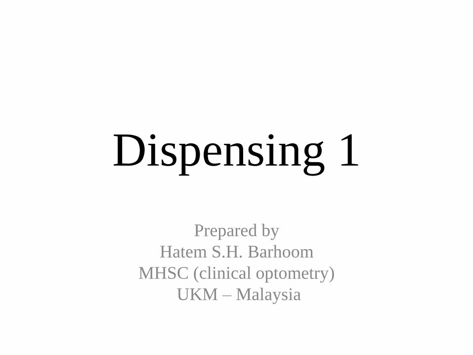
Syllabus
• Ophthalmic lenses
– Uses of spectacle lenses
– Measurement of lenses power
• Neutralisation
• Lensmeter – Uses
– Laying out lens
• Spectacle frames – Spectacle frame parts
– Spectacle frame dimensions
– Datum system
– Box system
• Glazing : – Preparing the lens and the frame
• Uncut lenses
• Finished lens shape and dimensions
• Effective lens diameter
• Laying off and Optical Centration
• Edge forms and finishes
• Fix the lens in the frame
• Ophthalmic lenses industry and
materials
• Spectacle frames industry and
materials
• Prisms: – Definition
– Uses
– Prismatic effect
Lens Identification
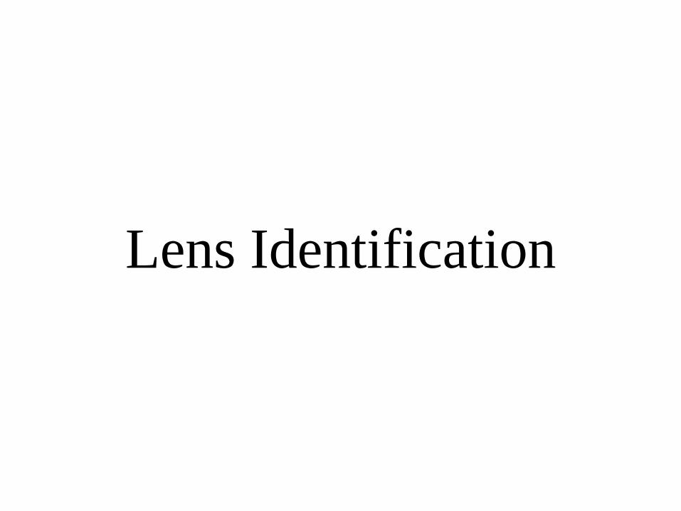
• Lens category : – Single vision lenses
– Segmented multifocal lenses
– Progressive addition lenses
– prism
• Lens material : – Plastic
• CR-39,
• Polycarbonate,
• High- Index Plastic Lenses
– Glass Lenses
• Lens readiness – finished lenses.
– Semi-finished
– uncut lenses
– stock single vision lenses.
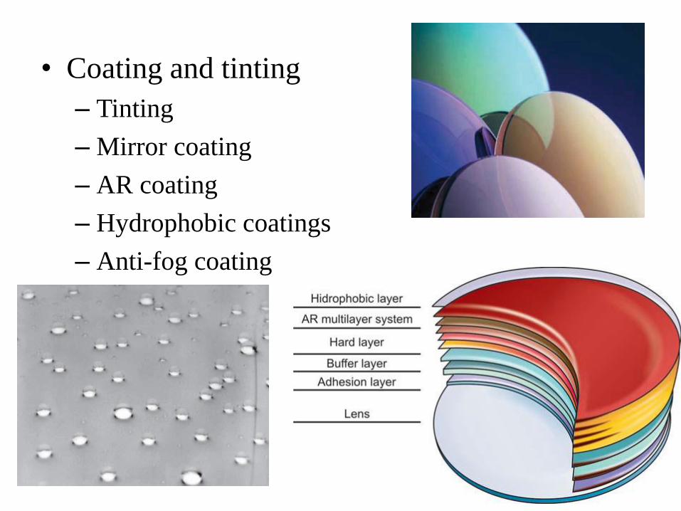
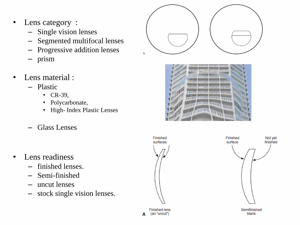
• Coating and tinting
– Tinting
– Mirror coating
– AR coating
– Hydrophobic coatings
– Anti-fog coating
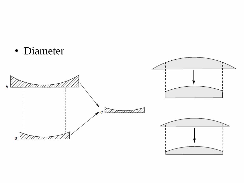
• Diameter
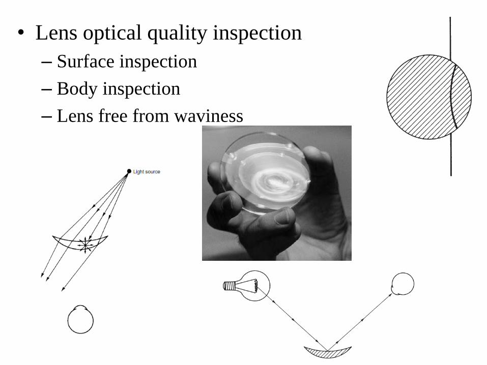
• Lens optical quality inspection
– Surface inspection
– Body inspection
– Lens free from waviness
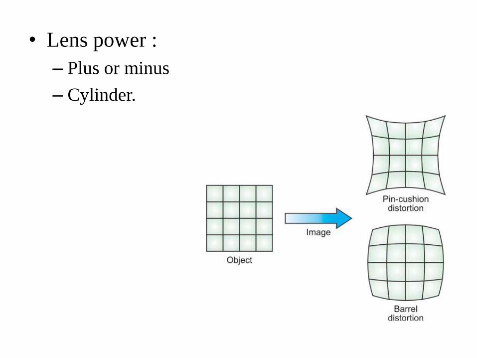
• Lens power :
– Plus or minus
– Cylinder.
Measurement of lens power
• Checking the lens power of spectacle
• Determining the specification of an unknown lenses
Methods :
1. Neutralization
2. Lens (Geneva ) clock
3. Focimeter
Neutralization
• Lens with unknown power combined with known lens power
>> zero power
• Known lens power neutralizing the unknown lens
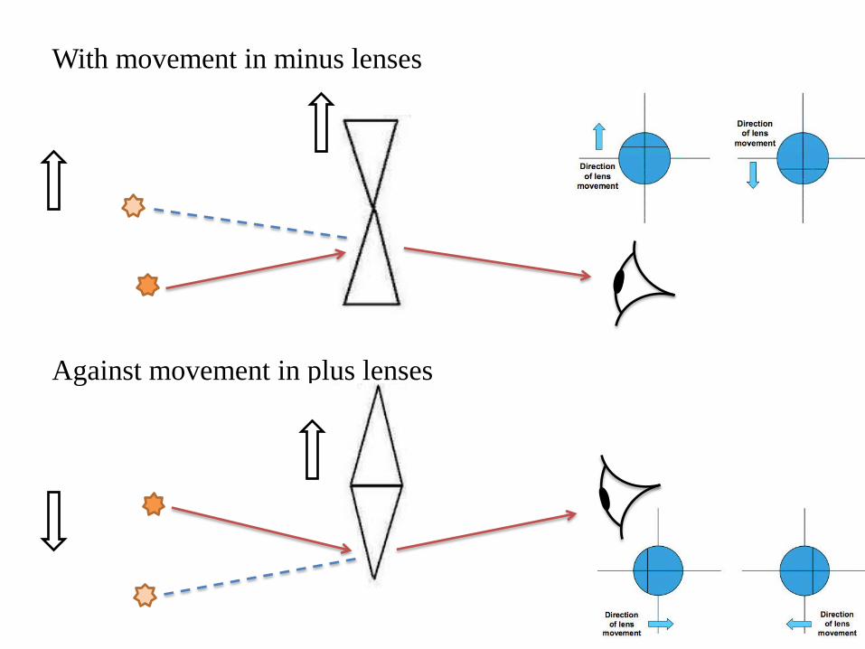
With movement in minus lenses
Against movement in plus lenses
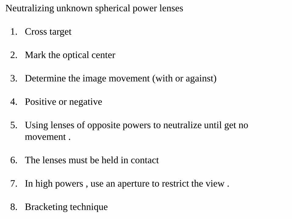
Neutralizing unknown spherical power lenses
1. Cross target
2. Mark the optical center
3. Determine the image movement (with or against)
4. Positive or negative
5. Using lenses of opposite powers to neutralize until get no
movement .
6. The lenses must be held in contact
7. In high powers , use an aperture to restrict the view .
8. Bracketing technique
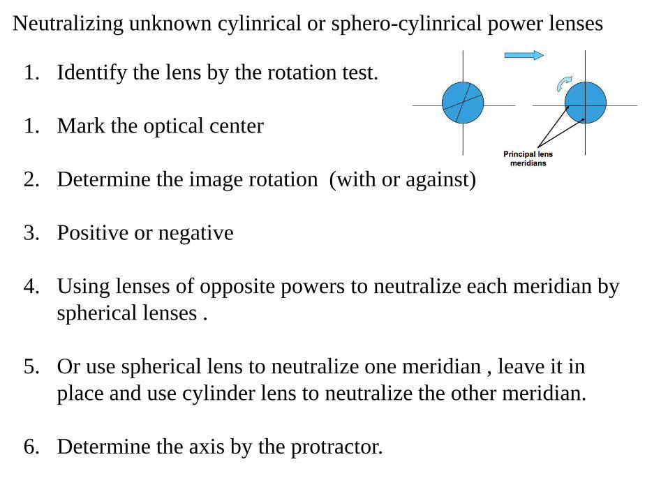
Neutralizing unknown cylinrical or sphero-cylinrical power lenses
1. Identify the lens by the rotation test.
1. Mark the optical center
2. Determine the image rotation (with or against)
3. Positive or negative
4. Using lenses of opposite powers to neutralize each meridian by
spherical lenses .
5. Or use spherical lens to neutralize one meridian , leave it in
place and use cylinder lens to neutralize the other meridian.
6. Determine the axis by the protractor.
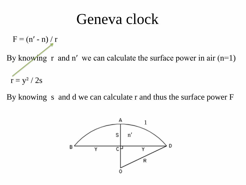
Geneva clock
F = (n′ - n) / r
r = y² / 2s
By knowing r and n′ we can calculate the surface power in air (n=1)
By knowing s and d we can calculate r and thus the surface power F
n′
1
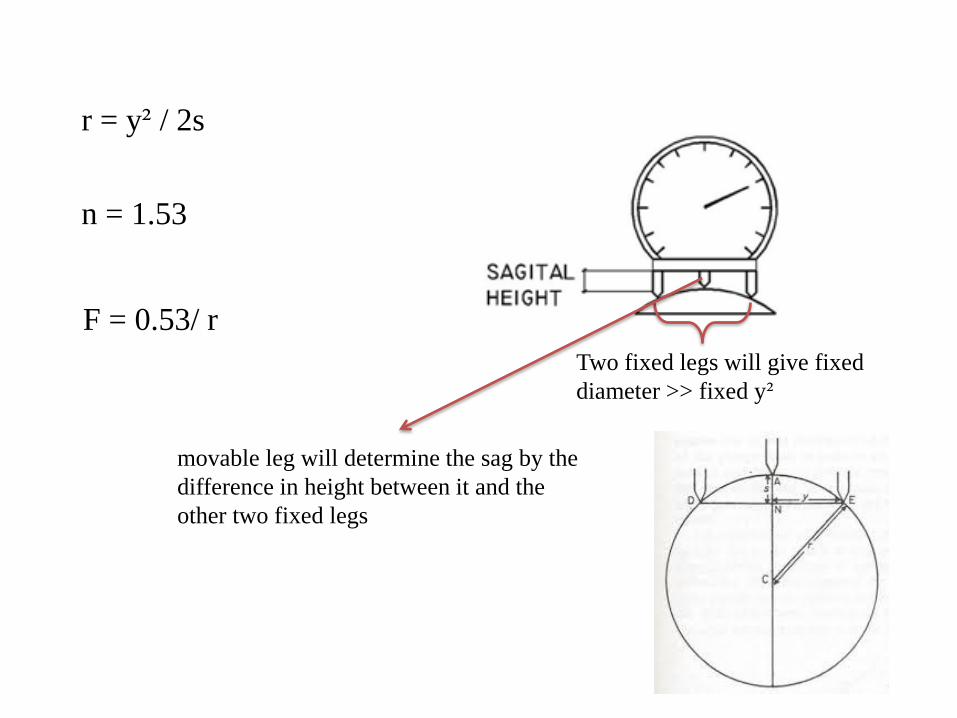
Two fixed legs will give fixed
diameter >> fixed y²
r = y² / 2s
movable leg will determine the sag by the
difference in height between it and the
other two fixed legs
F = 0.53/ r
n = 1.53
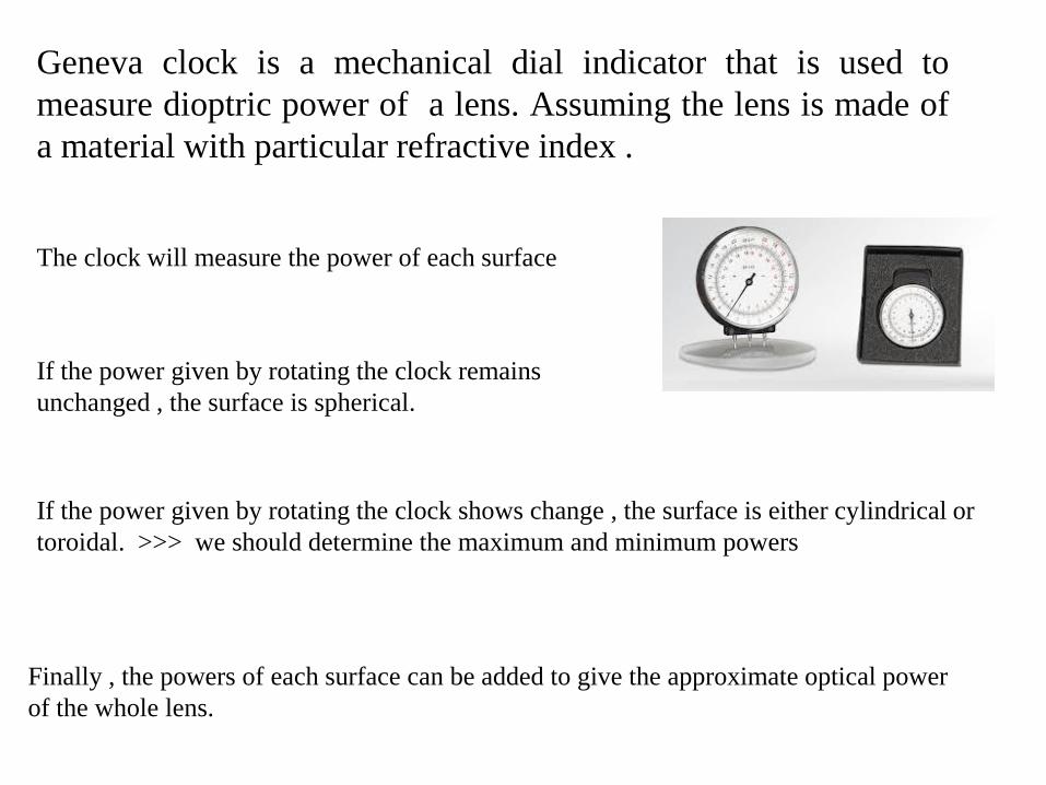
Geneva clock is a mechanical dial indicator that is used to
measure dioptric power of a lens. Assuming the lens is made of
a material with particular refractive index .
Finally , the powers of each surface can be added to give the approximate optical power
of the whole lens.
The clock will measure the power of each surface
If the power given by rotating the clock remains
unchanged , the surface is spherical.
If the power given by rotating the clock shows change , the surface is either cylindrical or
toroidal. >>> we should determine the maximum and minimum powers
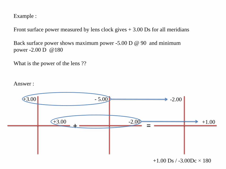
Example :
Front surface power measured by lens clock gives + 3.00 Ds for all meridians
Back surface power shows maximum power -5.00 D @ 90 and minimum
power -2.00 D @180
What is the power of the lens ??
Answer :
+3.00
- 5.00 +3.00
-2.00 + = +1.00
-2.00
+1.00 Ds / -3.00Dc × 180
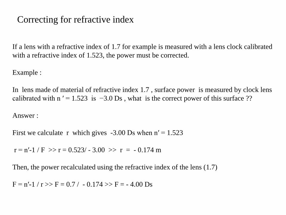
Correcting for refractive index
If a lens with a refractive index of 1.7 for example is measured with a lens clock calibrated
with a refractive index of 1.523, the power must be corrected.
Example :
In lens made of material of refractive index 1.7 , surface power is measured by clock lens
calibrated with n ′ = 1.523 is −3.0 Ds , what is the correct power of this surface ??
Answer :
First we calculate r which gives -3.00 Ds when n′ = 1.523
r = n′-1 / F >> r = 0.523/ - 3.00 >> r = - 0.174 m
Then, the power recalculated using the refractive index of the lens (1.7)
F = n′-1 / r >> F = 0.7 / - 0.174 >> F = - 4.00 Ds
Lensmeter
• Lensmeter (commercially known as a Lensometer, Focimeter, or
Vertometer)
• Used in : o Measuring the power of spectacles and contact lenses.
o Laying out lenses .
• Lensmeters may work manually or automatically.
• The most commonly used lensmeters are manual and use a crossed
line target.
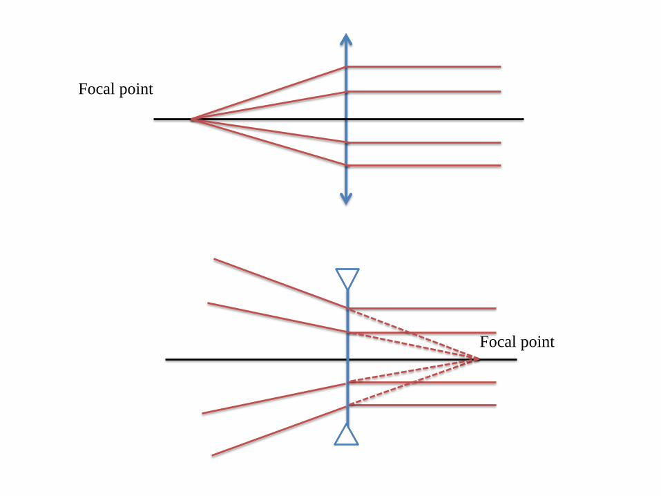
Focal point
Focal point
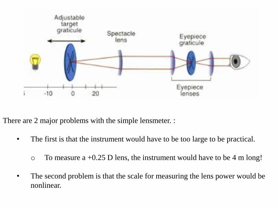
There are 2 major problems with the simple lensmeter. :
• The first is that the instrument would have to be too large to be practical.
o To measure a +0.25 D lens, the instrument would have to be 4 m long!
• The second problem is that the scale for measuring the lens power would be
nonlinear.
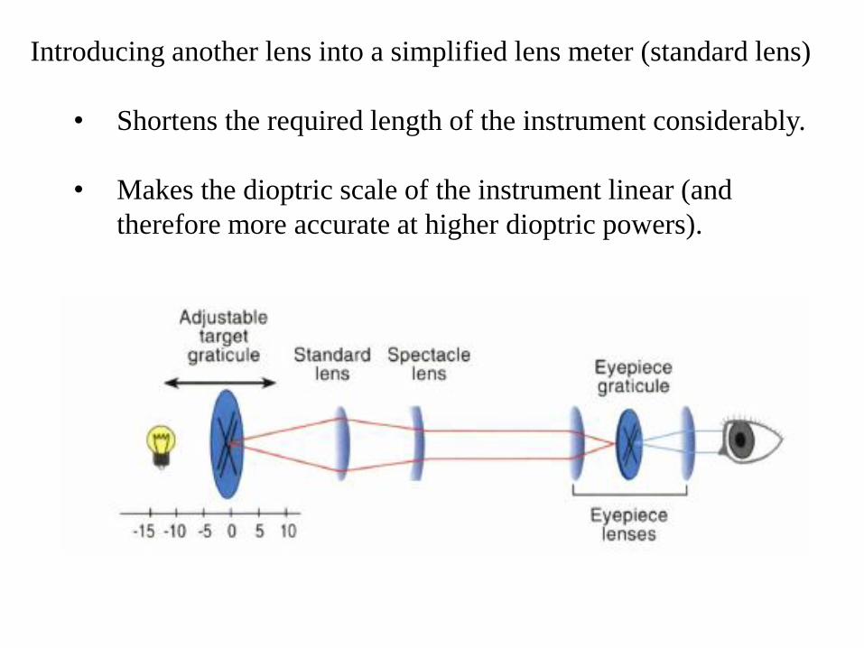
Introducing another lens into a simplified lens meter (standard lens)
• Shortens the required length of the instrument considerably.
• Makes the dioptric scale of the instrument linear (and
therefore more accurate at higher dioptric powers).
- 0 +
- 0 +
X ′
X ′
X
X
T
T
C
C
L
L
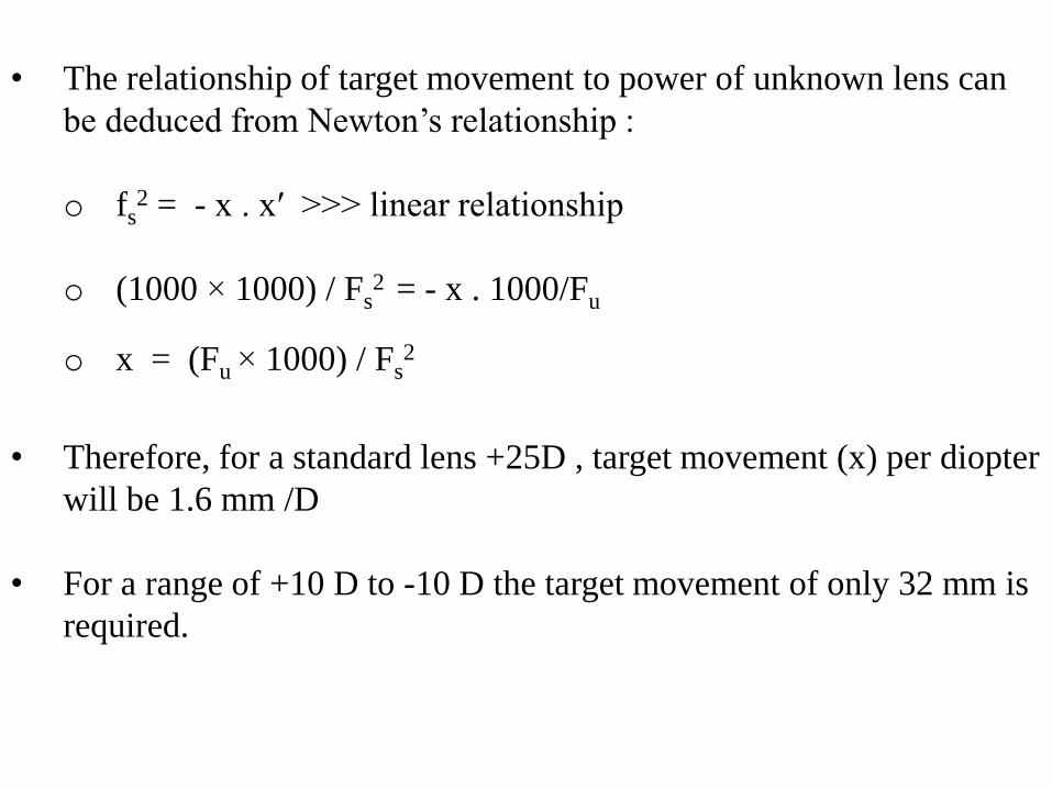
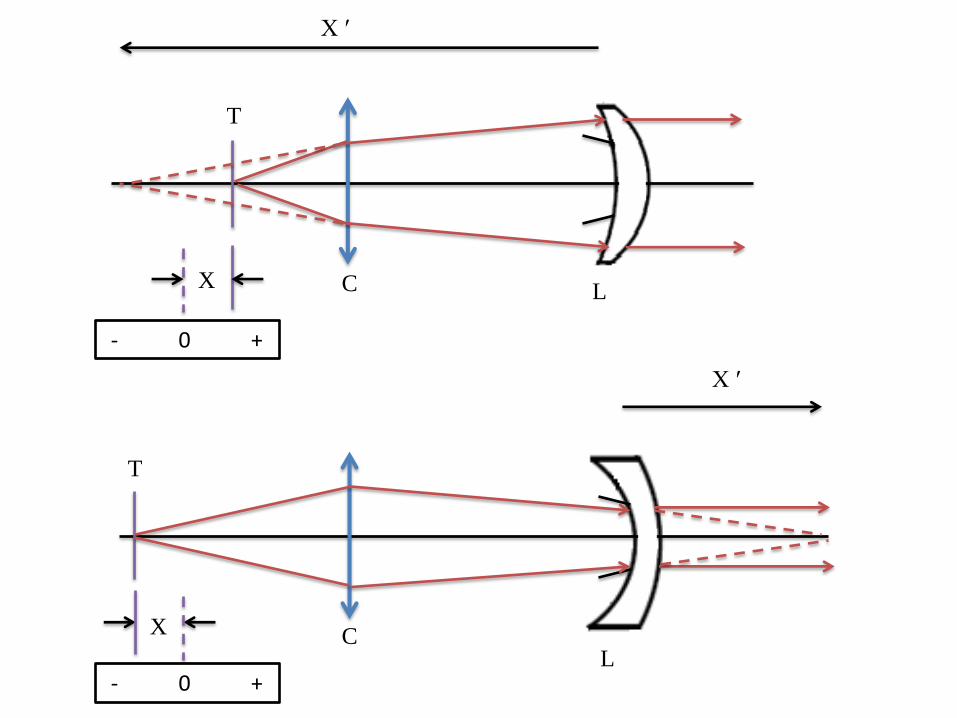
• The relationship of target movement to power of unknown lens can
be deduced from Newton’s relationship :
o fs2 = - x . x′ >>> linear relationship
o (1000 × 1000) / Fs2 = - x . 1000/Fu
o x = (Fu × 1000) / Fs2
• Therefore, for a standard lens +25D , target movement (x) per diopter
will be 1.6 mm /D
• For a range of +10 D to -10 D the target movement of only 32 mm is
required.
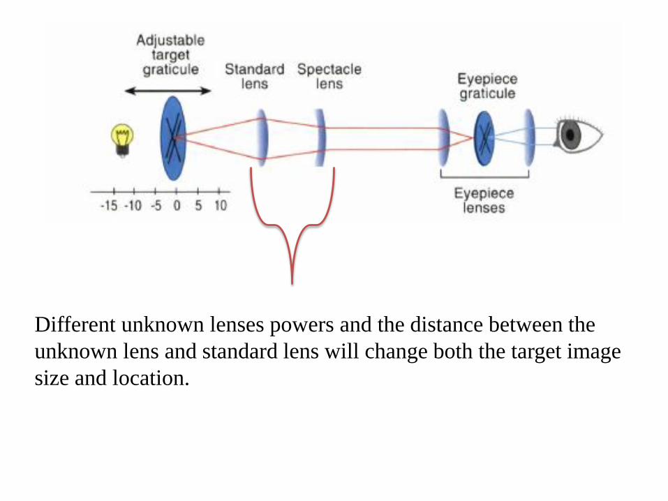
Different unknown lenses powers and the distance between the
unknown lens and standard lens will change both the target image
size and location.
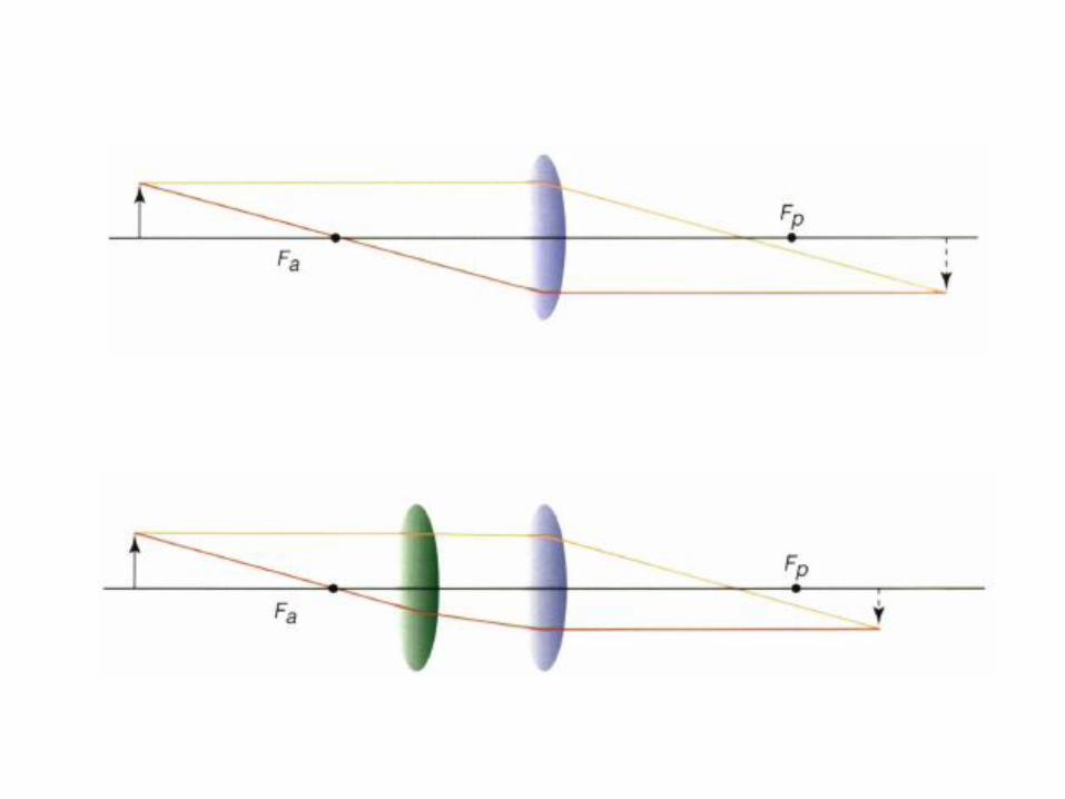
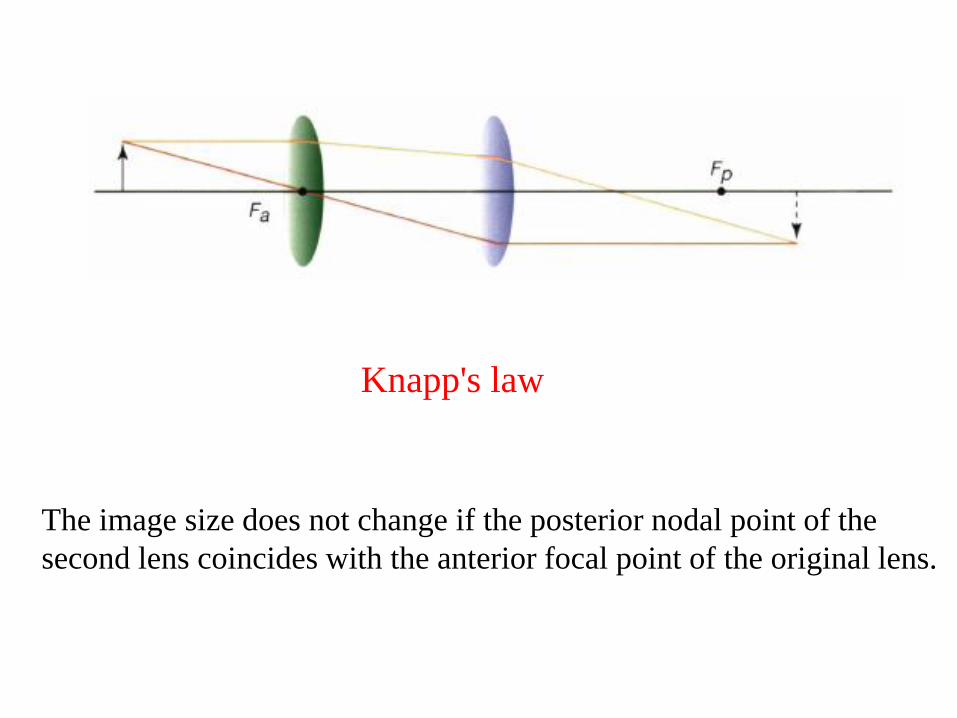
The image size does not change if the posterior nodal point of the
second lens coincides with the anterior focal point of the original lens.
Knapp's law
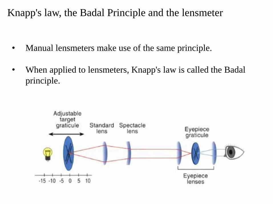
Knapp's law, the Badal Principle and the lensmeter
• Manual lensmeters make use of the same principle.
• When applied to lensmeters, Knapp's law is called the Badal
principle.
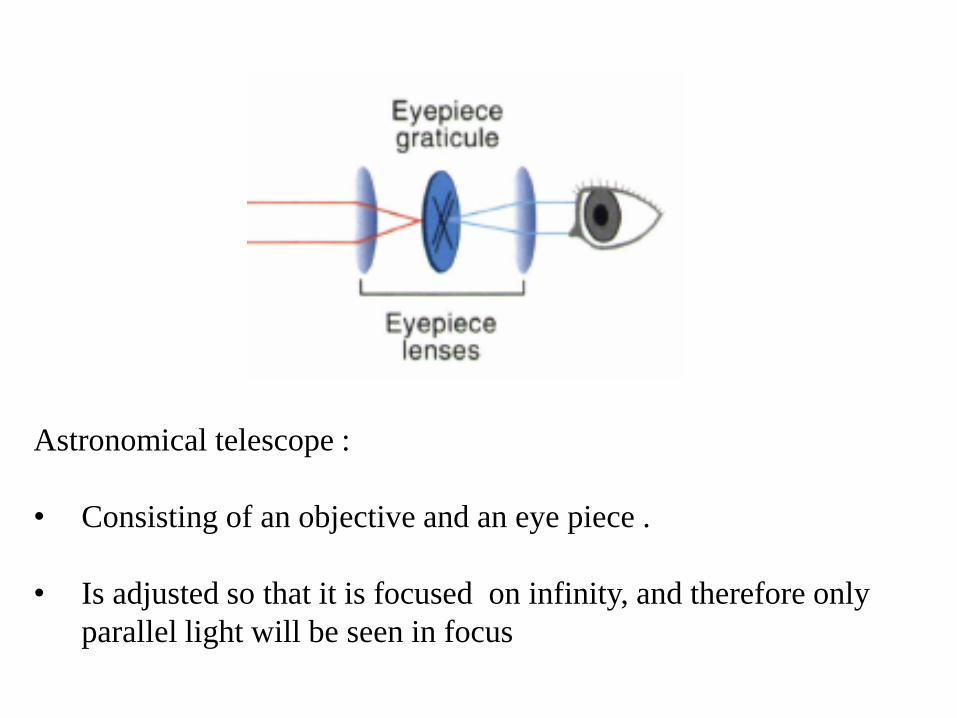
Astronomical telescope :
• Consisting of an objective and an eye piece .
• Is adjusted so that it is focused on infinity, and therefore only
parallel light will be seen in focus