Embed Size (px)
Citation preview
DPX System Operating Instructions
555 Theodore Fremd Ave., Rye, NY 10580 • 914-925-3261 • http://techsupport.mitsubishiimaging.com

Purup-Eskofot A/SCopenhagen DivisionIndustriparken 35-37DK-2750 BallerupDenmark
Tel.: (+45) 4473 6666Fax.: (+45) 4473 6767
DPX System - Operating InstructionsDoc. No.: 089-202-090
555 Theodore Fremd Ave., Rye, NY 10580 • 914-925-3261 • http://techsupport.mitsubishiimaging.com
Whilst every care has been taken in the preparation of this manual, no liability will beaccepted by Purup-Eskofot A/S arising out of any inaccuracies or omissions.
Interference with the equipment besides normal operation and user maintenance describedin the Operating Instructions Manual, must be carried out by a technician, who has beentrained/educated on the equipment in question.
Warning: This equipment generates, uses, and can radiate radio frequency energy and ifnot installed and used in accordance with the Service Manual, may cause interference toradio communications. It has been tested and found to comply with the limits for a Class Acomputing device pursuant to Subpart J of Part 15 of FCC Rules, which are designed toprovide reasonable protection against such interference when operated in a commercialenvironment. Operation of this equipment in a residential area is likely to cause interfer-ence in which case the user at his own expense will be required to take whatever measuresmay be necessary to correct the interference.
This document contains information proprietary to Purup-Eskofot A/S Any disclosure oruse of this information or any reproduction of this document for other than the specificpurpose for which it is intended is expressly prohibited except as Purup-Eskofot A/S mayotherwise agree to in writing.
555 Theodore Fremd Ave., Rye, NY 10580 • 914-925-3261 • http://techsupport.mitsubishiimaging.com

555 Theodore Fremd Ave., Rye, NY 10580 • 914-925-3261 • http://techsupport.mitsubishiimaging.com
Contents
Description . . . . . . . . . . . . . . . . . . . . . . . . . 2
Computer-to-Plate System (CtP)
Time Saving . . . . . . . . . . . . . . . . . . . . . . . . . . . 2Perfect Accuracy. . . . . . . . . . . . . . . . . . . . . . . . 2Intelligent Optimization . . . . . . . . . . . . . . . . . . 2High Quality Register . . . . . . . . . . . . . . . . . . . . 2Cost-Effective Production . . . . . . . . . . . . . . . . . 2
The DPX SYSTEM Unit
Exterior of Machine . . . . . . . . . . . . . . . . . . . . . 2Interior of Machine . . . . . . . . . . . . . . . . . . . . . . 3Sequence of Operation . . . . . . . . . . . . . . . . . . . 3
Basic Operation
Starting the DPX SYSTEM . . . . . . . . . . . . . . . 5Shutting Down the DPX SYSTEM . . . . . . . . . . 5
RIP Display
Program Manager . . . . . . . . . . . . . . . . . . . . . . . 6RipManager . . . . . . . . . . . . . . . . . . . . . . . . . . . 6RipMate . . . . . . . . . . . . . . . . . . . . . . . . . . . . . . 6PlateSetter Monitor . . . . . . . . . . . . . . . . . . . . . . 6
Output Controller
Active Queue . . . . . . . . . . . . . . . . . . . . . . . . . . 7Held Queue. . . . . . . . . . . . . . . . . . . . . . . . . . . . 7Job Names . . . . . . . . . . . . . . . . . . . . . . . . . . . . 7
Start/stop processing
Stop Output . . . . . . . . . . . . . . . . . . 7Start Output . . . . . . . . . . . . . . . . . . 7Repeating a Job. . . . . . . . . . . . . . . . . . . . . . . . . 8
Removing/deleting a Job. . . . . . . . . . . . . . . . . . 8Previewing a Job. . . . . . . . . . . . . . . . . . . . . . . . 8Connecting to the Front-End . . . . . . . . . . . . . . . 8Monitoring the RIP. . . . . . . . . . . . . . . . . . . . . . 9Missing font . . . . . . . . . . . . . . . . . . 9Missing calibration . . . . . . . . . . . . . . 9PostScript™ fault . . . . . . . . . . . . . . . 9
Monitoring the DPX SYSTEM Unit
BUSY/INFO. . . . . . . . . . . . . . . . . . 9INFO . . . . . . . . . . . . . . . . . . 9ERROR . . . . . . . . . . . . . . . . . . 9FAIL . . . . . . . . . . . . . . . . . . 10TEMPERATURES. . . . . . . . . . . . . . 10
Changing Plate Material. . . . . . . . . . . . . . . . 10
Emptying Punch Waste . . . . . . . . . . . . . . . . 13
Developer Unit
Draining the Developer Unit . . . . . . . . . . . . . 13Cleaning of the Developer Unit . . . . . . . . . . . 14
Filling of the Developer Unit
Troubleshooting
Error messages . . . . . . . . . . . . . . . . 16
Technical Specifications . . . . . . . . . . . . . . 20DPX SYSTEM Digital Platesetter. . . . . . . . . . 20Integrated Plate Processing Module. . . . . . . . . 20RIP Module . . . . . . . . . . . . . . . . . . . . . . . . . . 20Operation Condition . . . . . . . . . . . . . . . . . . . . 20Storage Condition . . . . . . . . . . . . . . . . . . . . . . 20
Page i
Table of Contents DPX System Operating Instructions
555 Theodore Fremd Ave., Rye, NY 10580 • 914-925-3261 • http://techsupport.mitsubishiimaging.com

555 Theodore Fremd Ave., Rye, NY 10580 • 914-925-3261 • http://techsupport.mitsubishiimaging.com
1.DescriptionComputer-to-Plate System (CtP)The DPX SYSTEM digital platesetter producespress-ready plates for a variety of printing jobs.The entire process only takes a few minutes and iscarried out in full daylight.
This highly versatile platesetter is capable of man-aging a variety of colour demands, satisfying awide range of imaging needs. The DPX SYSTEMtargets all black and white applications as well ashigh-end spot-colour, and quality 4-colour jobs.
Time SavingThe DPX SYSTEM bypasses the conventionalfilm processing stage entirely by integrating func-tions such as edge-to-edge exposure, plate punch-ing, processing, cutting to size, drying andstacking, in one compact unit.
Perfect AccuracyBased on an internal drum imaging device with aLED laser (670 nm), the DPX SYSTEM offers un-matched image accuracy and repeatability, ensur-ing that each separation is in register.
Intelligent OptimizationThe DPX SYSTEM contains two cassettes, hold-ing up to 61 metres of material each. If the samematerial is loaded in both cassettes, the unit willautomatically switch to the second cassette whenthe first is empty, allowing uninterrupted produc-tion for hours.
High Quality RegisterAn internal register punch system is optional.
Cost-Effective Production
The DPX SYSTEM is a highly productive andeconomic solution. The technology has proven toreduce the processing time by 50%, without com-promising the ultimate quality.
The DPX SYSTEM Unit
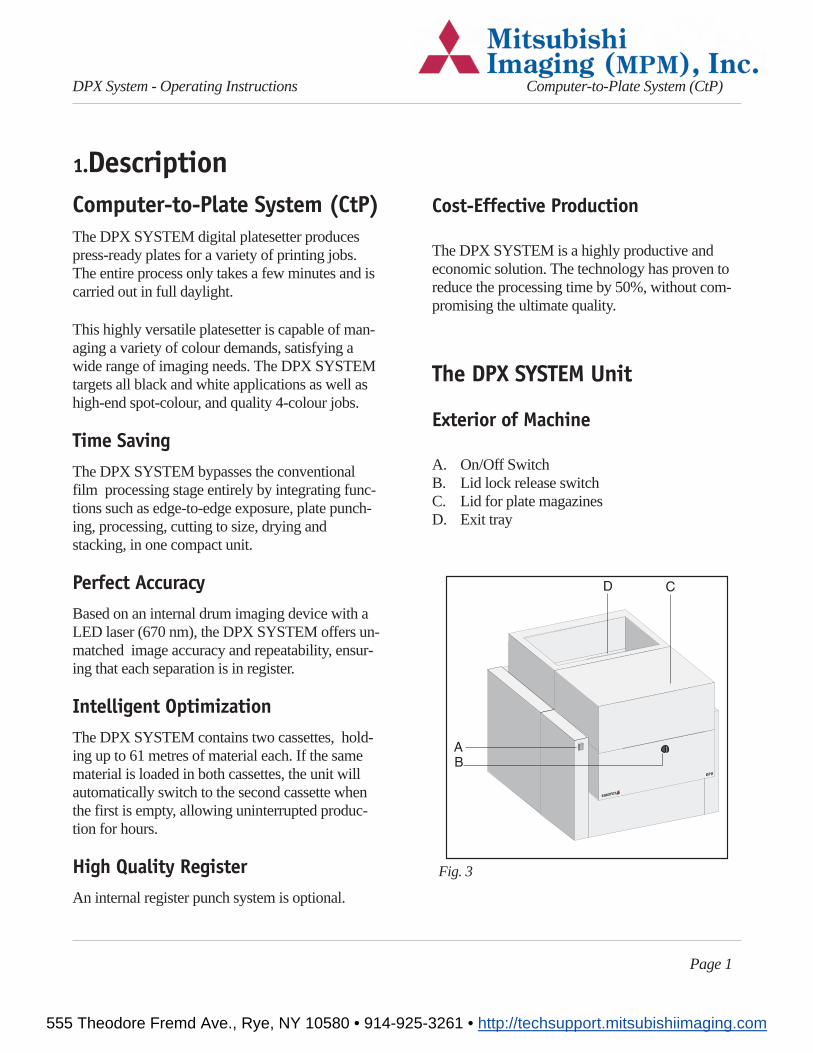
Exterior of Machine
A. On/Off SwitchB. Lid lock release switchC. Lid for plate magazinesD. Exit tray
Page 1
DPX System - Operating Instructions Computer-to-Plate System (CtP)
Fig. 3
555 Theodore Fremd Ave., Rye, NY 10580 • 914-925-3261 • http://techsupport.mitsubishiimaging.com
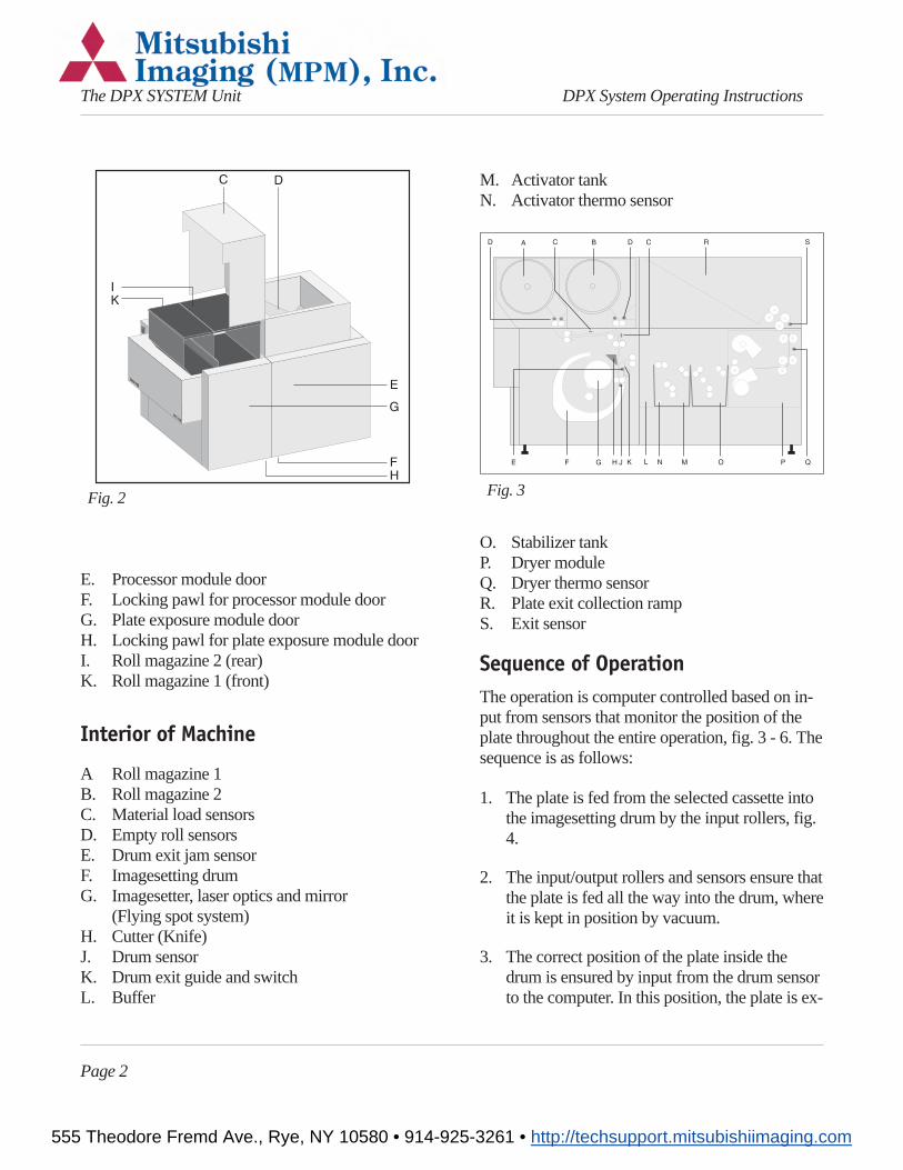
E. Processor module doorF. Locking pawl for processor module doorG. Plate exposure module doorH. Locking pawl for plate exposure module doorI. Roll magazine 2 (rear)K. Roll magazine 1 (front)
Interior of Machine
A Roll magazine 1B. Roll magazine 2C. Material load sensorsD. Empty roll sensorsE. Drum exit jam sensorF. Imagesetting drumG. Imagesetter, laser optics and mirror
(Flying spot system)H. Cutter (Knife)J. Drum sensorK. Drum exit guide and switchL. Buffer
M. Activator tankN. Activator thermo sensor
O. Stabilizer tankP. Dryer moduleQ. Dryer thermo sensorR. Plate exit collection rampS. Exit sensor
Sequence of OperationThe operation is computer controlled based on in-put from sensors that monitor the position of theplate throughout the entire operation, fig. 3 - 6. Thesequence is as follows:
1. The plate is fed from the selected cassette intothe imagesetting drum by the input rollers, fig.4.
2. The input/output rollers and sensors ensure thatthe plate is fed all the way into the drum, whereit is kept in position by vacuum.
3. The correct position of the plate inside thedrum is ensured by input from the drum sensorto the computer. In this position, the plate is ex-
Page 2
The DPX SYSTEM Unit DPX System Operating Instructions
Fig. 3Fig. 2
555 Theodore Fremd Ave., Rye, NY 10580 • 914-925-3261 • http://techsupport.mitsubishiimaging.com
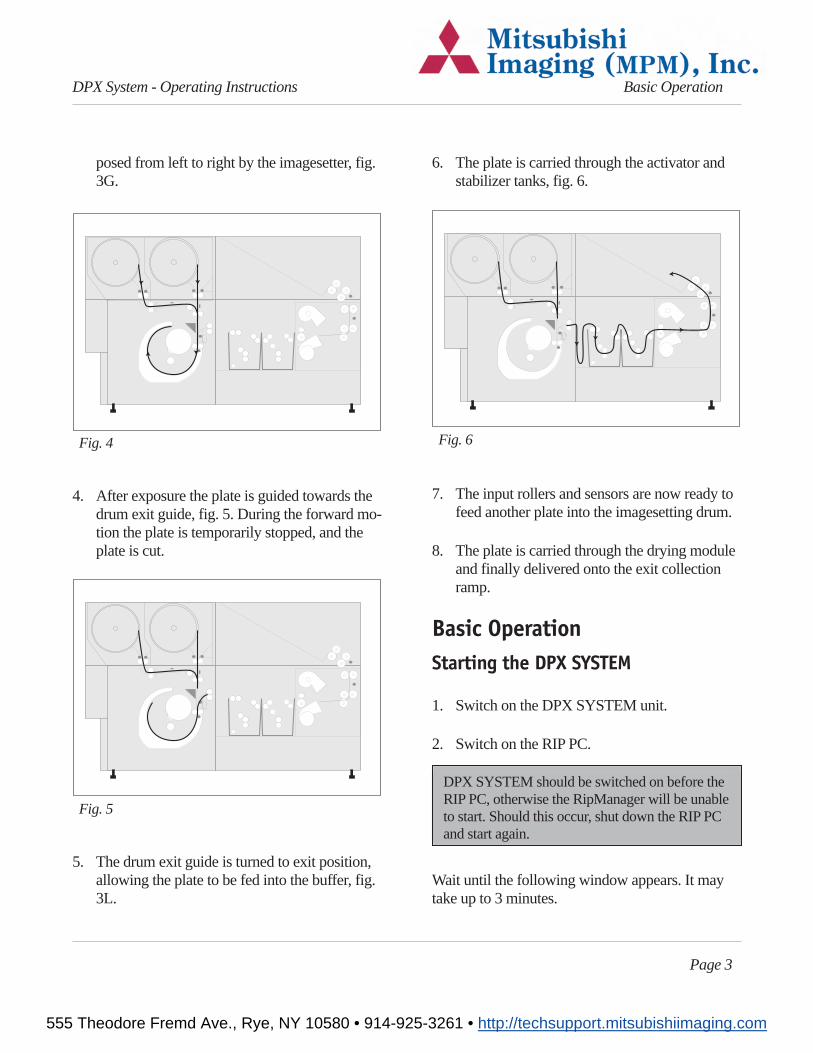
posed from left to right by the imagesetter, fig.3G.
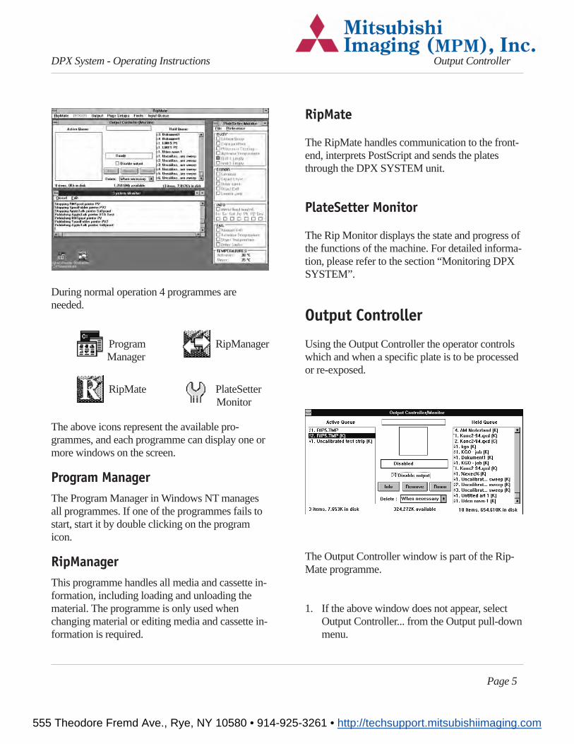
4. After exposure the plate is guided towards thedrum exit guide, fig. 5. During the forward mo-tion the plate is temporarily stopped, and theplate is cut.
5. The drum exit guide is turned to exit position,allowing the plate to be fed into the buffer, fig.3L.
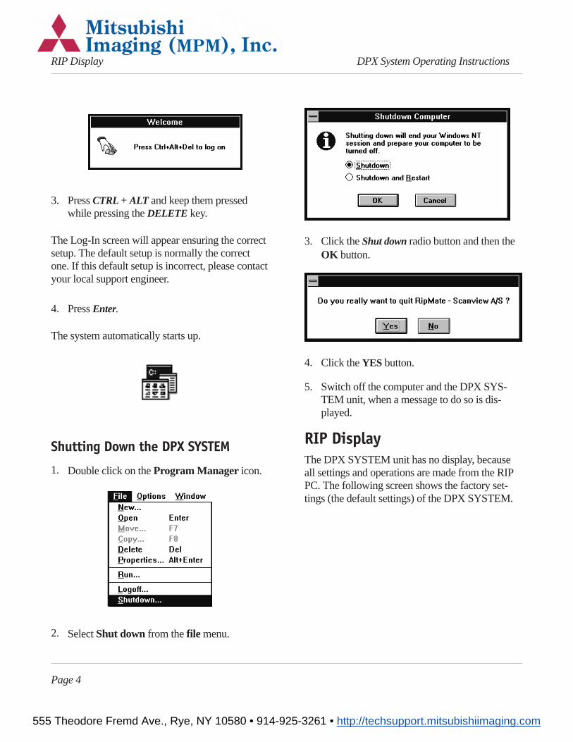
6. The plate is carried through the activator andstabilizer tanks, fig. 6.
7. The input rollers and sensors are now ready tofeed another plate into the imagesetting drum.
8. The plate is carried through the drying moduleand finally delivered onto the exit collectionramp.
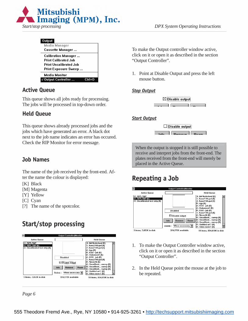
Basic OperationStarting the DPX SYSTEM
1. Switch on the DPX SYSTEM unit.
2. Switch on the RIP PC.
DPX SYSTEM should be switched on before theRIP PC, otherwise the RipManager will be unableto start. Should this occur, shut down the RIP PCand start again.
Wait until the following window appears. It maytake up to 3 minutes.
Page 3
DPX System - Operating Instructions Basic Operation
Fig. 5
Fig. 6Fig. 4
555 Theodore Fremd Ave., Rye, NY 10580 • 914-925-3261 • http://techsupport.mitsubishiimaging.com
3. PressCTRL+ ALT and keep them pressedwhile pressing theDELETE key.
The Log-In screen will appear ensuring the correctsetup. The default setup is normally the correctone. If this default setup is incorrect, please contactyour local support engineer.
4. PressEnter.
The system automatically starts up.
Shutting Down the DPX SYSTEM
1. Double click on theProgram Manager icon.
2. SelectShut down from thefile menu.
3. Click theShut downradio button and then theOK button.
4. Click theYES button.
5. Switch off the computer and the DPX SYS-TEM unit, when a message to do so is dis-played.
RIP DisplayThe DPX SYSTEM unit has no display, becauseall settings and operations are made from the RIPPC. The following screen shows the factory set-tings (the default settings) of the DPX SYSTEM.
Page 4
RIP Display DPX System Operating Instructions
555 Theodore Fremd Ave., Rye, NY 10580 • 914-925-3261 • http://techsupport.mitsubishiimaging.com
During normal operation 4 programmes areneeded.
Program RipManagerManager
RipMate PlateSetterMonitor
The above icons represent the available pro-grammes, and each programme can display one ormore windows on the screen.
Program ManagerThe Program Manager in Windows NT managesall programmes. If one of the programmes fails tostart, start it by double clicking on the programicon.
RipManagerThis programme handles all media and cassette in-formation, including loading and unloading thematerial. The programme is only used whenchanging material or editing media and cassette in-formation is required.
RipMate
The RipMate handles communication to the front-end, interprets PostScript and sends the platesthrough the DPX SYSTEM unit.
PlateSetter Monitor
The Rip Monitor displays the state and progress ofthe functions of the machine. For detailed informa-tion, please refer to the section “Monitoring DPXSYSTEM”.
Output Controller
Using the Output Controller the operator controlswhich and when a specific plate is to be processedor re-exposed.
The Output Controller window is part of the Rip-Mate programme.
1. If the above window does not appear, selectOutput Controller... from the Output pull-downmenu.
Page 5
DPX System - Operating Instructions Output Controller
555 Theodore Fremd Ave., Rye, NY 10580 • 914-925-3261 • http://techsupport.mitsubishiimaging.com
Active QueueThis queue shows all jobs ready for processing.The jobs will be processed in top-down order.
Held Queue
This queue shows already processed jobs and thejobs which have generated an error. A black dotnext to the job name indicates an error has occured.Check the RIP Monitor for error message.
Job Names
The name of the job received by the front-end. Af-ter the name the colour is displayed:[K] Black[M] Magenta[Y] Yellow[C] Cyan[?] The name of the spotcolor.
Start/stop processing
To make the Output controller window active,click on it or open it as described in the section“Output Controller”.
1. Point at Disable Output and press the leftmouse button.
Stop Output
Start Output
When the output is stopped it is still possible toreceive and interpret jobs from the front-end. Theplates received from the front-end will merely beplaced in the Active Queue.
Repeating a Job
1. To make the Output Controller window active,click on it or open it as described in the section“Output Controller”.
2. In the Held Queue point the mouse at the job tobe repeated.
Page 6
Start/stop processing DPX System Operating Instructions
555 Theodore Fremd Ave., Rye, NY 10580 • 914-925-3261 • http://techsupport.mitsubishiimaging.com
3. Press the left mouse button and hold it downwhile pulling the job from the Held Queue tothe Active Queue. Release the mouse button.
The job has now been moved from the Held Queueto the Active Queue and will be exposed accordingto its position in the queue.
By placing the job at the top of the Active Queue,it will be exposed before the other plates.
Removing/Deleting a Job
1. To make the Output Controller window active,click on it or open it as described in the section“Output Controller”.
2. Point at the job in the Held Queue whichshould be removed and press the left mousebutton down.
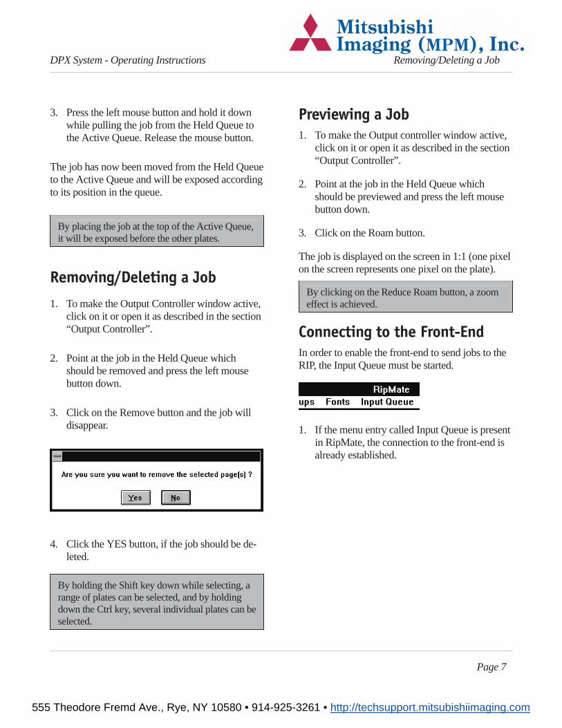
3. Click on the Remove button and the job willdisappear.
4. Click the YES button, if the job should be de-leted.
By holding the Shift key down while selecting, arange of plates can be selected, and by holdingdown the Ctrl key, several individual plates can beselected.
Previewing a Job1. To make the Output controller window active,
click on it or open it as described in the section“Output Controller”.
2. Point at the job in the Held Queue whichshould be previewed and press the left mousebutton down.
3. Click on the Roam button.
The job is displayed on the screen in 1:1 (one pixelon the screen represents one pixel on the plate).
By clicking on the Reduce Roam button, a zoomeffect is achieved.
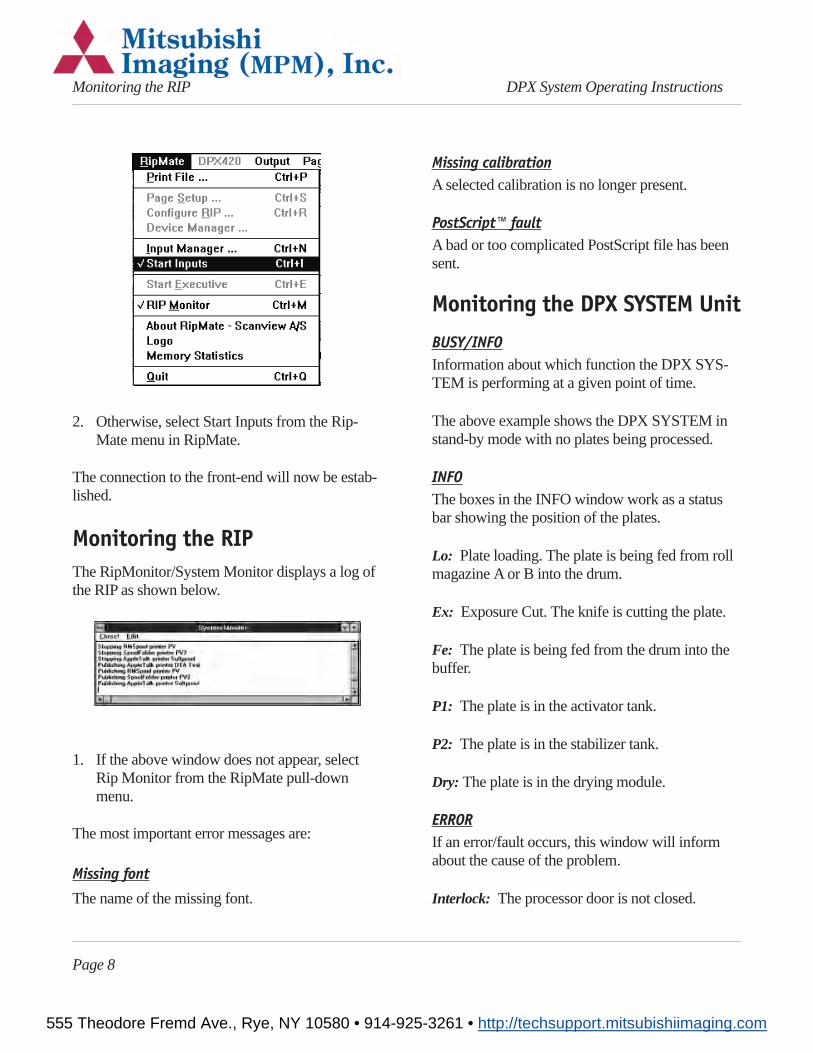
Connecting to the Front-EndIn order to enable the front-end to send jobs to theRIP, the Input Queue must be started.
1. If the menu entry called Input Queue is presentin RipMate, the connection to the front-end isalready established.
Page 7
DPX System - Operating Instructions Removing/Deleting a Job
555 Theodore Fremd Ave., Rye, NY 10580 • 914-925-3261 • http://techsupport.mitsubishiimaging.com
2. Otherwise, select Start Inputs from the Rip-Mate menu in RipMate.
The connection to the front-end will now be estab-lished.
Monitoring the RIPThe RipMonitor/System Monitor displays a log ofthe RIP as shown below.
1. If the above window does not appear, selectRip Monitor from the RipMate pull-downmenu.
The most important error messages are:
Missing font
The name of the missing font.
Missing calibrationA selected calibration is no longer present.
PostScript™ faultA bad or too complicated PostScript file has beensent.
Monitoring the DPX SYSTEM Unit
BUSY/INFOInformation about which function the DPX SYS-TEM is performing at a given point of time.
The above example shows the DPX SYSTEM instand-by mode with no plates being processed.
INFOThe boxes in the INFO window work as a statusbar showing the position of the plates.
Lo: Plate loading. The plate is being fed from rollmagazine A or B into the drum.
Ex: Exposure Cut. The knife is cutting the plate.
Fe: The plate is being fed from the drum into thebuffer.
P1: The plate is in the activator tank.
P2: The plate is in the stabilizer tank.
Dry: The plate is in the drying module.
ERRORIf an error/fault occurs, this window will informabout the cause of the problem.
Interlock: The processor door is not closed.
Page 8
Monitoring the RIP DPX System Operating Instructions
555 Theodore Fremd Ave., Rye, NY 10580 • 914-925-3261 • http://techsupport.mitsubishiimaging.com
Liquid Level: The level in the activator tank is tolow. Change the chemistry or refill the replenish-ment bottles
Drive Load: The processor stopped due to over-load of the processor motor. Check whether thereis a plate in the processor section.
Dryer Exit: Jam in the processor section. Open theprocessor and make sure that no plates arejammed.
Loader Jam: Jam in the exposure section. Thefault numbers refer to the following:
Fault number 0-100:Something in the exposuresection went wrong during a sequence. Shuttingdown the system, remove any plate pieces in thedrum, and restart the system.
Fault number 110-112:A jam in the punch tools.Shut the system down and clean the tools beforerestarting the system.
If a plate jam error occurs, shut down the system,remove the jammed plate before restarting thesystem. If plate jam reoccurs, contact the localservice engineer.
FAILVaccum fail: The vaccum level was incorrect. Ex-amine the plate and repeat the job if necessary. Ifthe fail reoccurs, contact the local service engineer.
Activator temp: The temperature deviates morethan 2°C from the specified developer temperature.Do not process a plate until the temperature is cor-rect.
Dryer Temp: The dryer temperature deviates morethan 2°C from the specified dryer temperature. The
plates might not be completely dry when theycome out.
Drive Tacho: The processor is not running. Checkthe processing section for jams, and make sure theactivator and stabilizer tanks are not covered withdirt. If everything seems in order, and the processoris still not running, contact the local service engi-neer.
Temperatures
Indicates the actual temperature in the activatortank and in the drying unit.
Changing Plate Material
Unloading material
The following description set forth that the systemis installed and setup according to the installationinstructions and user guide.
1. Stop processing by activating the Disable out-put button. See section “Start/stop processing”.
2. Activate the RipManager icon by double click-ing on it.
3. Select Media Management from the DPXSYSTEM pull-down menu.
The following window appears:
Page 9
DPX System - Operating Instructions Changing Plate Material
555 Theodore Fremd Ave., Rye, NY 10580 • 914-925-3261 • http://techsupport.mitsubishiimaging.com
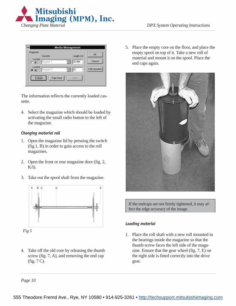
The information reflects the currently loaded cas-sette.
4. Select the magazine which should be loaded byactivating the small radio button to the left ofthe magazine.
Changing material roll
1. Open the magazine lid by pressing the switch(fig.1, B) in order to gain access to the rollmagazines.
2. Open the front or rear magazine door (fig. 2,K/I).
3. Take out the spool shaft from the magazine.
4. Take off the old core by releasing the thumbscrew (fig. 7, A), and removing the end cap(fig. 7 C).
5. Place the empty core on the floor, and place theempty spool on top of it. Take a new roll ofmaterial and mount it on the spool. Place theend caps again.
If the endcaps are not firmly tightened, it may af-fect the edge accuracy of the image.
Loading material
1. Place the roll shaft with a new roll mounted inthe bearings inside the magazine so that thethumb screw faces the left side of the maga-zine. Ensure that the gear wheel (fig. 7, E) onthe right side is fitted correctly into the drivegear.
Page 10
Changing Plate Material DPX System Operating Instructions
Fig 5
555 Theodore Fremd Ave., Rye, NY 10580 • 914-925-3261 • http://techsupport.mitsubishiimaging.com
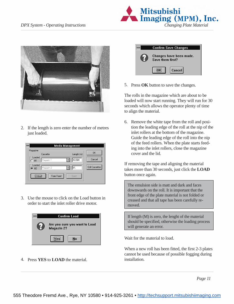
2. If the length is zero enter the number of metresjust loaded.
3. Use the mouse to click on the Load button inorder to start the inlet roller drive motor.
4. PressYES to LOAD the material.
5. PressOK button to save the changes.
The rolls in the magazine which are about to beloaded will now start running. They will run for 30seconds which allows the operator plenty of timeto align the material.
6. Remove the white tape from the roll and posi-tion the leading edge of the roll at the nip of theinlet rollers at the bottom of the magazine.Guide the leading edge of the roll into the nipof the feed rollers. When the plate starts feed-ing into the inlet rollers, close the magazinecover and the lid.
If removing the tape and aligning the materialtakes more than 30 seconds, just click theLOADbutton once again.
The emulsion side is matt and dark and facesdownwards on the roll. It is important that thefront edge of the plate material is not folded orcreased and that all tape has been carefully re-moved.
If length (M) is zero, the lenght of the materialshould be specified, otherwise the loading processwill generate an error.
Wait for the material to load.
When a new roll has been fitted, the first 2-3 platescannot be used because of possible fogging duringinstallation.
Page 11
DPX System - Operating Instructions Changing Plate Material
555 Theodore Fremd Ave., Rye, NY 10580 • 914-925-3261 • http://techsupport.mitsubishiimaging.com
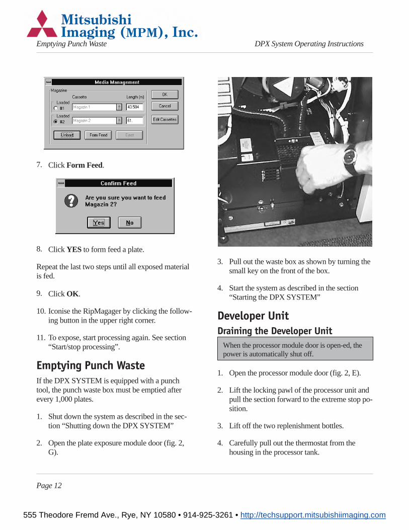
7. Click Form Feed.
8. Click YES to form feed a plate.
Repeat the last two steps until all exposed materialis fed.
9. Click OK.
10. Iconise the RipMagager by clicking the follow-ing button in the upper right corner.
11. To expose, start processing again. See section“Start/stop processing”.
Emptying Punch WasteIf the DPX SYSTEM is equipped with a punchtool, the punch waste box must be emptied afterevery 1,000 plates.
1. Shut down the system as described in the sec-tion “Shutting down the DPX SYSTEM”
2. Open the plate exposure module door (fig. 2,G).
3. Pull out the waste box as shown by turning thesmall key on the front of the box.
4. Start the system as described in the section“Starting the DPX SYSTEM”
Developer UnitDraining the Developer Unit
When the processor module door is open-ed, thepower is automatically shut off.
1. Open the processor module door (fig. 2, E).
2. Lift the locking pawl of the processor unit andpull the section forward to the extreme stop po-sition.
3. Lift off the two replenishment bottles.
4. Carefully pull out the thermostat from thehousing in the processor tank.
Page 12
Emptying Punch Waste DPX System Operating Instructions
555 Theodore Fremd Ave., Rye, NY 10580 • 914-925-3261 • http://techsupport.mitsubishiimaging.com
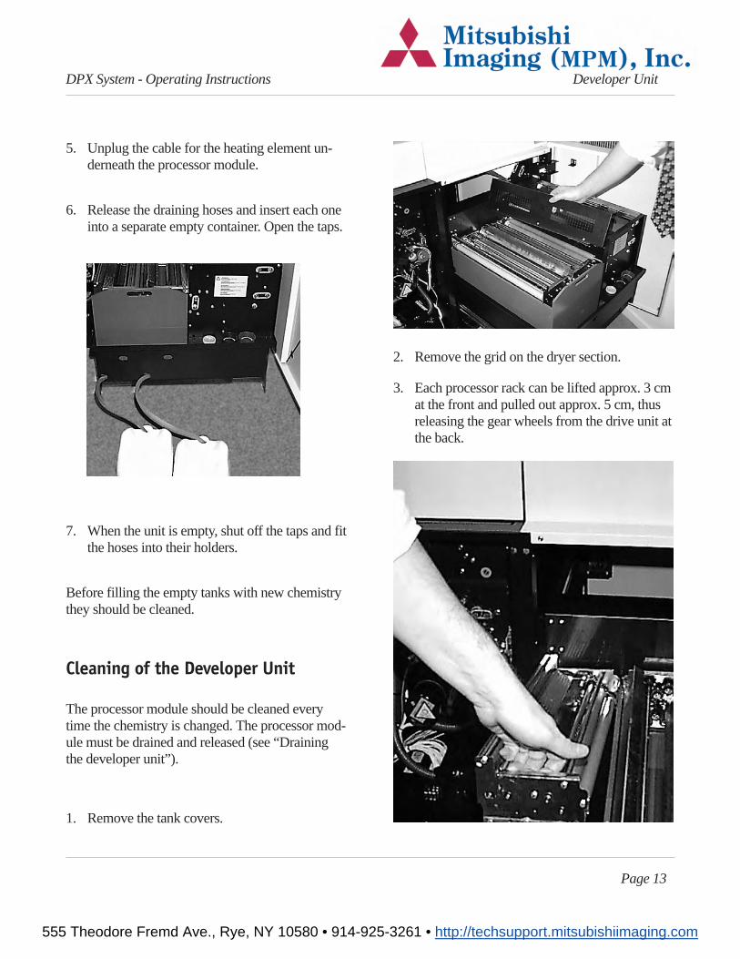
5. Unplug the cable for the heating element un-derneath the processor module.
6. Release the draining hoses and insert each oneinto a separate empty container. Open the taps.
7. When the unit is empty, shut off the taps and fitthe hoses into their holders.
Before filling the empty tanks with new chemistrythey should be cleaned.
Cleaning of the Developer Unit
The processor module should be cleaned everytime the chemistry is changed. The processor mod-ule must be drained and released (see “Drainingthe developer unit”).
1. Remove the tank covers.
2. Remove the grid on the dryer section.
3. Each processor rack can be lifted approx. 3 cmat the front and pulled out approx. 5 cm, thusreleasing the gear wheels from the drive unit atthe back.
Page 13
DPX System - Operating Instructions Developer Unit
555 Theodore Fremd Ave., Rye, NY 10580 • 914-925-3261 • http://techsupport.mitsubishiimaging.com
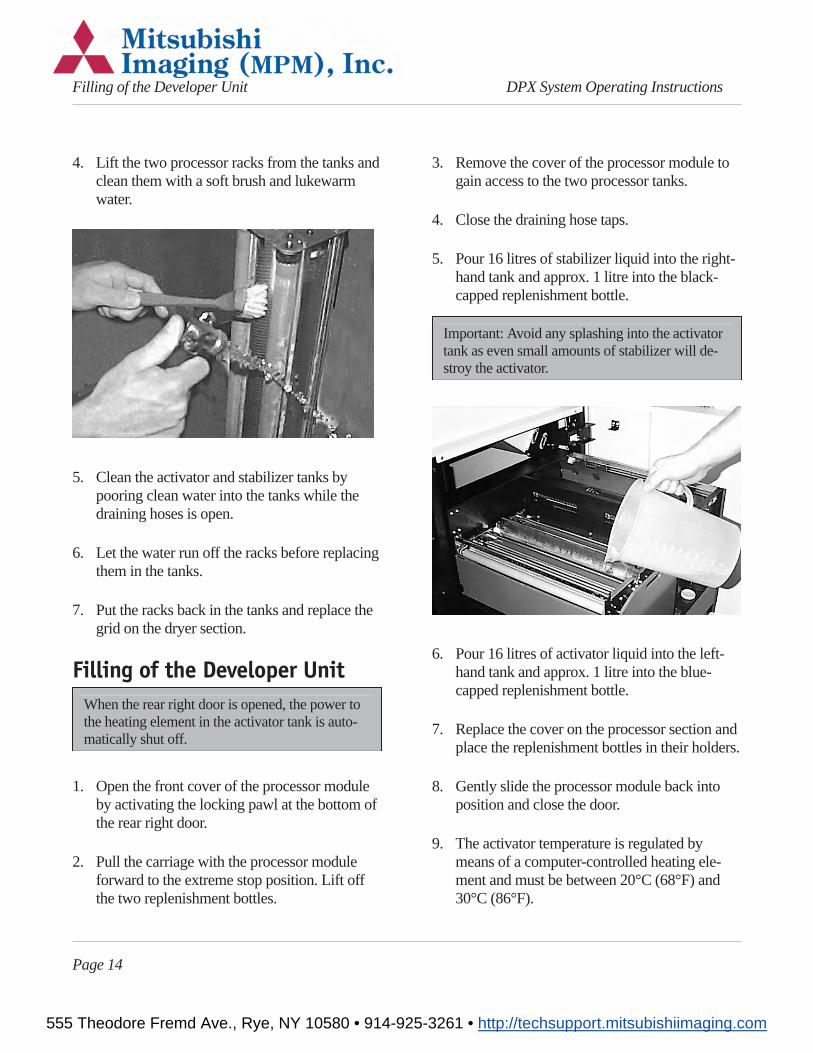
4. Lift the two processor racks from the tanks andclean them with a soft brush and lukewarmwater.
5. Clean the activator and stabilizer tanks bypooring clean water into the tanks while thedraining hoses is open.
6. Let the water run off the racks before replacingthem in the tanks.
7. Put the racks back in the tanks and replace thegrid on the dryer section.
Filling of the Developer UnitWhen the rear right door is opened, the power tothe heating element in the activator tank is auto-matically shut off.
1. Open the front cover of the processor moduleby activating the locking pawl at the bottom ofthe rear right door.
2. Pull the carriage with the processor moduleforward to the extreme stop position. Lift offthe two replenishment bottles.
3. Remove the cover of the processor module togain access to the two processor tanks.
4. Close the draining hose taps.
5. Pour 16 litres of stabilizer liquid into the right-hand tank and approx. 1 litre into the black-capped replenishment bottle.
Important: Avoid any splashing into the activatortank as even small amounts of stabilizer will de-stroy the activator.
6. Pour 16 litres of activator liquid into the left-hand tank and approx. 1 litre into the blue-capped replenishment bottle.
7. Replace the cover on the processor section andplace the replenishment bottles in their holders.
8. Gently slide the processor module back intoposition and close the door.
9. The activator temperature is regulated bymeans of a computer-controlled heating ele-ment and must be between 20°C (68°F) and30°C (86°F).
Page 14
Filling of the Developer Unit DPX System Operating Instructions
555 Theodore Fremd Ave., Rye, NY 10580 • 914-925-3261 • http://techsupport.mitsubishiimaging.com
Warning: Never turn on the power unless theprocessor module is filled or the power plug forthe heating element is removed, as this may causeoverheating and damage to the processor module.
Troubleshooting
Error messages
The DPX SYSTEM displays error messages in theOutput Controller and in the PlateSetter Monitor.Look for the error messages and refer to this sec-tion for troubleshooting.
The RipManager and RipMate will not start up
Whenever the RipManager starts up it searches forthe DPX SYSTEM unit through the SCSI chain. Ifit is unable to find the DPX SYSTEM unit or ifthere is an error on the DPX SYSTEM unit theRipManager does not start. Because the RipMan-ager is iconised it is not possible to see exactlywhich error occurred. To display an error messagedo the following:
1. Double click on the Program Manager icon.
2. Find the RipManager programme group.
3. Double click on the RipManager icon.
The error message will now be displayed. Refer tothe Troubleshooting section for further help.
Imagesetter not foundIf “Imagesetter not found” is displayed in the Rip-Manager window during startup, the DPX SYS-TEM does not report on the SCSI chain.
1. Check that the door to the plate exposure mod-ule door (fig 2. E) is closed.
2. Try shutting down the system and restarting it.See section “Shutting down the DPX SYS-TEM”.
If the DPX SYSTEM unit is not switched on bef-ore the RIP PC, this error message will occur.
Cover openThe cover to the plate processing module door (fig2. E) is not closed.
Close the door (fig 2. E).
Double click on the RipManager icon in the pro-gramme manager to launch the RIP again.
Interface card failedThe connection through the SCSI Interface cable islost, and the RIP cannot communicate with theDPX SYSTEM.
1. Shut down the system as described in section“Shutting down the DPX SYSTEM”
2. Start the DPX SYSTEM as described in “Start-ing the DPX SYSTEM”
Printer caught upRipMate has not had the necessary system re-sources to transfer image data to the DPX SYS-
Page 15
DPX System - Operating Instructions Troubleshooting
555 Theodore Fremd Ave., Rye, NY 10580 • 914-925-3261 • http://techsupport.mitsubishiimaging.com
TEM, due to Windows NT system or anotherprogramme.
1. Try repeating the job.
Undefined command “set calibration”
The current plate setup can not find a calibration.This might be due to the setup of the calibration orhow the received PostScript job was set up. Referto the RipMate user guide for further information.
Font not found
The system is set up to refuse processing a platewhen a font is missing in the PostScript job.
DPX SYSTEM reports to the Rip Monitor whichfont is missing.
Loader Jam: 0 - 100
An error in the exposure section of the DPX SYS-TEM has occured. Generally, this error messagedescribes a situation, where a sensor has not seenthe material passing by at the expected time.
1. Shut down the system and restart it.
Continue exposing if the error has disappeared,otherwise
2. Shut down the system.
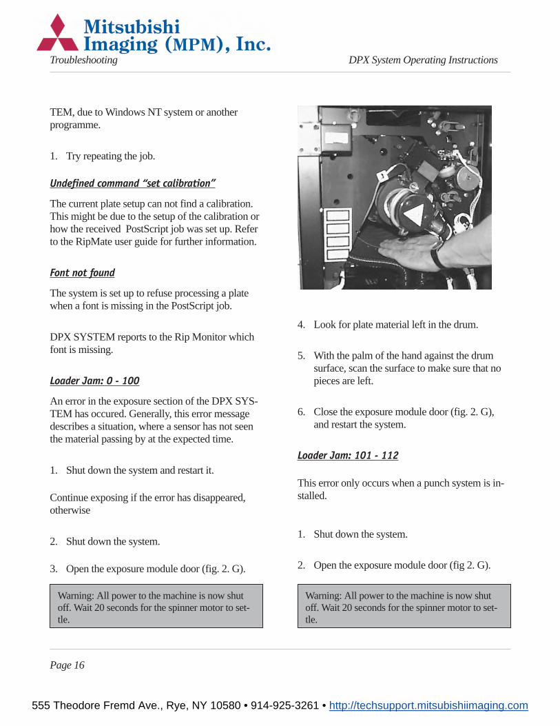
3. Open the exposure module door (fig. 2. G).
Warning: All power to the machine is now shutoff. Wait 20 seconds for the spinner motor to set-tle.
4. Look for plate material left in the drum.
5. With the palm of the hand against the drumsurface, scan the surface to make sure that nopieces are left.
6. Close the exposure module door (fig. 2. G),and restart the system.
Loader Jam: 101 - 112
This error only occurs when a punch system is in-stalled.
1. Shut down the system.
2. Open the exposure module door (fig 2. G).
Warning: All power to the machine is now shutoff. Wait 20 seconds for the spinner motor to set-tle.
Page 16
Troubleshooting DPX System Operating Instructions
555 Theodore Fremd Ave., Rye, NY 10580 • 914-925-3261 • http://techsupport.mitsubishiimaging.com
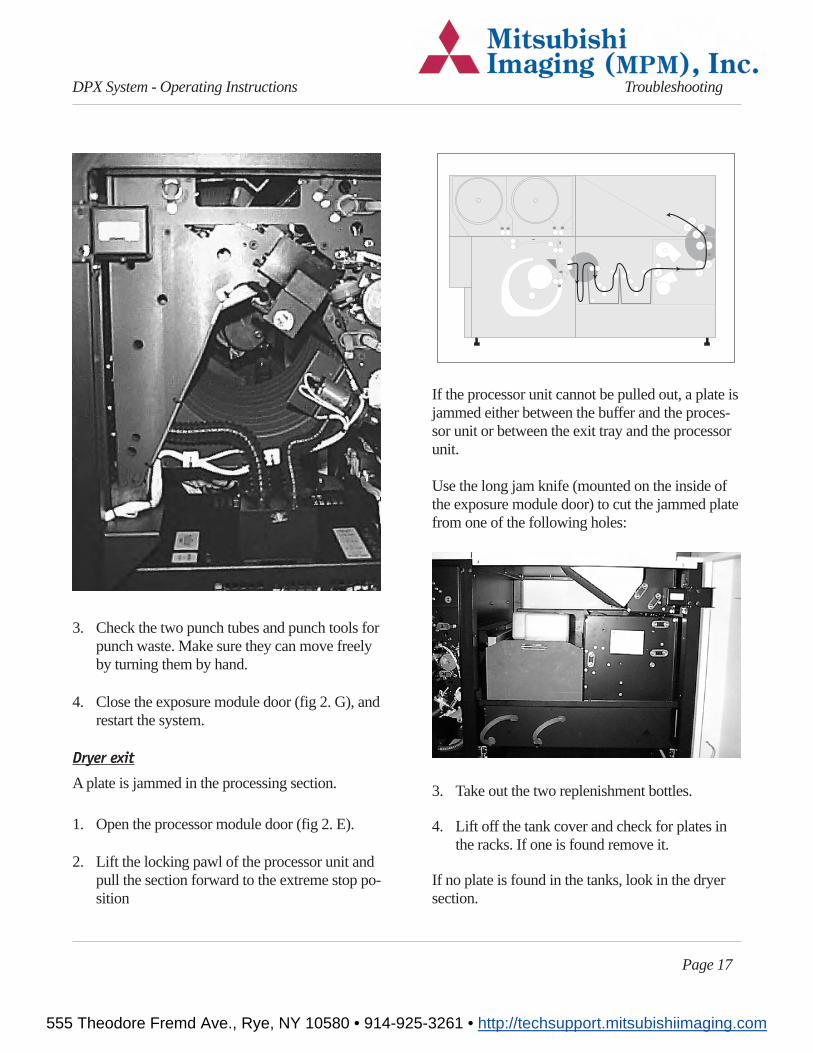
3. Check the two punch tubes and punch tools forpunch waste. Make sure they can move freelyby turning them by hand.
4. Close the exposure module door (fig 2. G), andrestart the system.
Dryer exit
A plate is jammed in the processing section.
1. Open the processor module door (fig 2. E).
2. Lift the locking pawl of the processor unit andpull the section forward to the extreme stop po-sition
If the processor unit cannot be pulled out, a plate isjammed either between the buffer and the proces-sor unit or between the exit tray and the processorunit.
Use the long jam knife (mounted on the inside ofthe exposure module door) to cut the jammed platefrom one of the following holes:
3. Take out the two replenishment bottles.
4. Lift off the tank cover and check for plates inthe racks. If one is found remove it.
If no plate is found in the tanks, look in the dryersection.
Page 17
DPX System - Operating Instructions Troubleshooting
555 Theodore Fremd Ave., Rye, NY 10580 • 914-925-3261 • http://techsupport.mitsubishiimaging.com
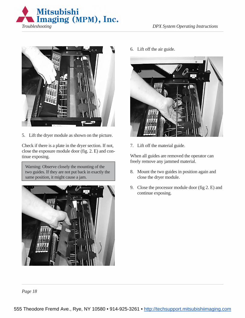
5. Lift the dryer module as shown on the picture.
Check if there is a plate in the dryer section. If not,close the exposure module door (fig. 2. E) and con-tinue exposing.
Warning: Observe closely the mounting of thetwo guides. If they are not put back in exactly thesame position, it might cause a jam.
6. Lift off the air guide.
7. Lift off the material guide.
When all guides are removed the operator canfreely remove any jammed material.
8. Mount the two guides in position again andclose the dryer module.
9. Close the processor module door (fig 2. E) andcontinue exposing.
Page 18
Troubleshooting DPX System Operating Instructions
555 Theodore Fremd Ave., Rye, NY 10580 • 914-925-3261 • http://techsupport.mitsubishiimaging.com
2.Technical SpecificationsDPX SYSTEM Digital PlatesetterType: Digital Plate Exposure SystemMax. plate format: 460 x 550 mm / 16.5 x 21.6"Max. image/exposure area: 436 x 546 mm / 16.3 x 21.4"Imaging technology: Internal drumLight source: 670 nm visible red laser diodePlate material: Photo-direct polyester platesResolution: 900 - 2540 dpi (variable)Screen ruling: 56 - 175 lpi (determined by the
plate material and press)Dot Range: 5 - 95%Image sizerepeatability: ± 1/100 mmImage positioningrepeatability: ± 0.5 mm related to edge
± 0.2 mm related to punchMaterial loading: Two supply cassettesDimensions (WxHxD): 1020 x 1055 x 1366mmWeight: 454 kgPower Consumption:13 Amp. without punch, 16Amp. with punchOptional: Register Punch System (land-
scape and/or portrait punch)Integrated Plate Processing ModulePrinciple: Variable speedProcessor: Activator and stabilizerDryer: Temperature controlled, hot airReplenishment: Level controlStacking: 50 - 100 platesRIP ModuleSystem: Windows NT hostedFeatures: Harlequin Core (Script-Works)
HPS screeningPostscript level 2
Network: Compatible with PC , Macin-tosh and UNIX networks
Interface: Standard SCSI -2 Differential.
Operation ConditionOperation temperature range:18°C-28°CHumidity: 25% - 80% RH non condens-ingStorage ConditionOperation temperature range:5°C-50°CHumidity: 25% - 80% RH non
condensing
Page 19
DPX System - Operating Instructions Troubleshooting
555 Theodore Fremd Ave., Rye, NY 10580 • 914-925-3261 • http://techsupport.mitsubishiimaging.com

555 Theodore Fremd Ave., Rye, NY 10580 • 914-925-3261 • http://techsupport.mitsubishiimaging.com