Embed Size (px)
Citation preview
Industrial Embedded Systems - Design for Harsh Environment -
Dr. Alexander Walsch
Part V
WS 2012/13
Technical University Munich (TUM)
Architecture and Detailed Design- Overview -
Slide2A. Walsch, IN2244 WS 2012/13
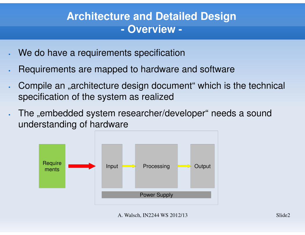
� We do have a requirements specification
� Requirements are mapped to hardware and software
� Compile an „architecture design document“ which is the technical
specification of the system as realized
� The „embedded system researcher/developer“ needs a sound
understanding of hardware
Input Processing Output
Power Supply
Requirements
Approach
Slide3A. Walsch, IN2244 WS 2012/13
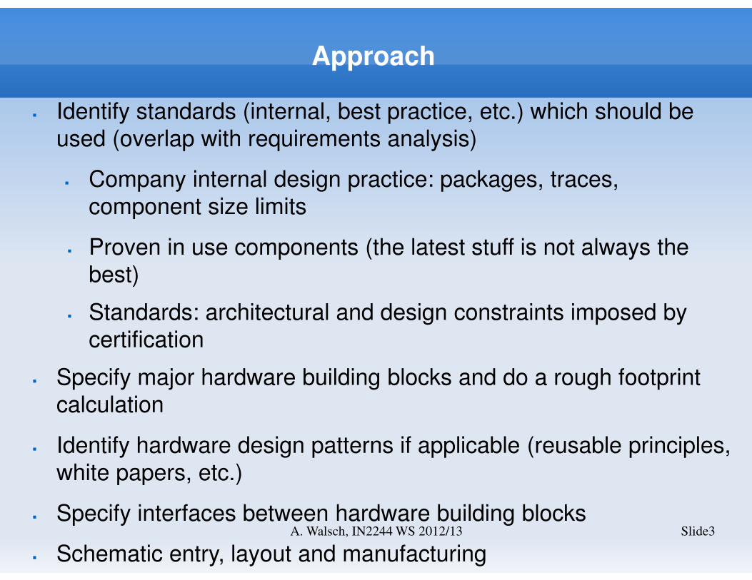
� Identify standards (internal, best practice, etc.) which should be
used (overlap with requirements analysis)
� Company internal design practice: packages, traces,
component size limits
� Proven in use components (the latest stuff is not always the
best)
� Standards: architectural and design constraints imposed by
certification
� Specify major hardware building blocks and do a rough footprint
calculation
� Identify hardware design patterns if applicable (reusable principles,
white papers, etc.)
� Specify interfaces between hardware building blocks
� Schematic entry, layout and manufacturing
Reliability Standards
Slide4A. Walsch, IN2244 WS 2012/13
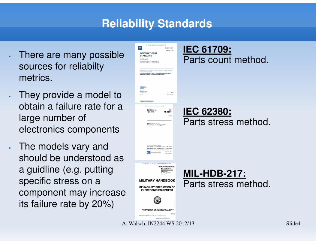
IEC 61709:Parts count method.
IEC 62380:Parts stress method.
MIL-HDB-217:Parts stress method.
� There are many possible
sources for reliabilty
metrics.
� They provide a model to
obtain a failure rate for a
large number of
electronics components
� The models vary and
should be understood as
a guidline (e.g. putting
specific stress on a
component may increase
its failure rate by 20%)
Reliability Standards II (from wikipedia)
Slide5A. Walsch, IN2244 WS 2012/13
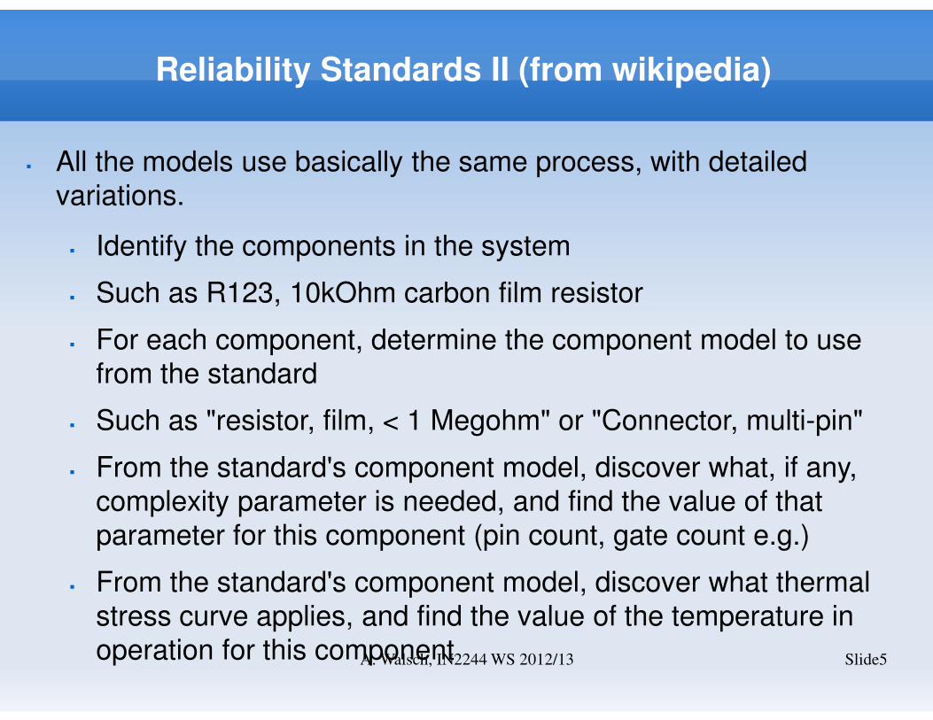
� All the models use basically the same process, with detailed
variations.
� Identify the components in the system
� Such as R123, 10kOhm carbon film resistor
� For each component, determine the component model to use
from the standard
� Such as "resistor, film, < 1 Megohm" or "Connector, multi-pin"
� From the standard's component model, discover what, if any,
complexity parameter is needed, and find the value of that
parameter for this component (pin count, gate count e.g.)
� From the standard's component model, discover what thermal
stress curve applies, and find the value of the temperature in
operation for this component
Reliability Standards III (from wikipedia)
Slide6A. Walsch, IN2244 WS 2012/13
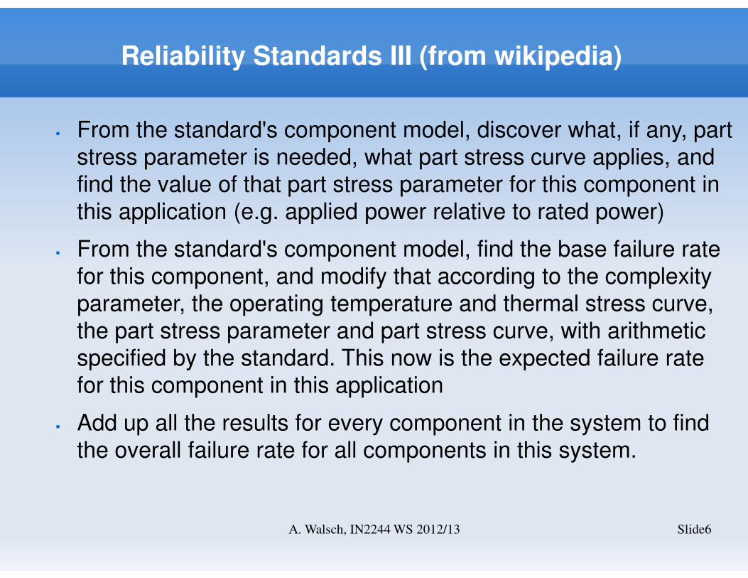
� From the standard's component model, discover what, if any, part
stress parameter is needed, what part stress curve applies, and
find the value of that part stress parameter for this component in
this application (e.g. applied power relative to rated power)
� From the standard's component model, find the base failure rate
for this component, and modify that according to the complexity
parameter, the operating temperature and thermal stress curve,
the part stress parameter and part stress curve, with arithmetic
specified by the standard. This now is the expected failure rate
for this component in this application
� Add up all the results for every component in the system to find
the overall failure rate for all components in this system.
Graphical Representation
Slide7A. Walsch, IN2244 WS 2012/13
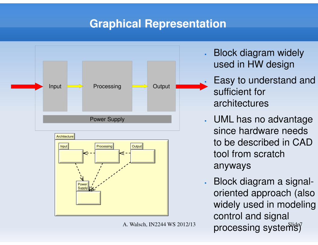
Input Processing Output
Power Supply
Architecture
Input Processing Output
PowerSupply
Input Processing Output
PowerSupply
� Block diagram widely
used in HW design
� Easy to understand and
sufficient for
architectures
� UML has no advantage
since hardware needs
to be described in CAD
tool from scratch
anyways
� Block diagram a signal-
oriented approach (also
widely used in modeling
control and signal
processing systems)
Major System Hardware Components
Slide8A. Walsch, IN2244 WS 2012/13
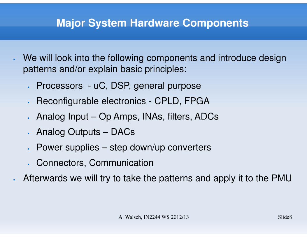
� We will look into the following components and introduce design
patterns and/or explain basic principles:
� Processors - uC, DSP, general purpose
� Reconfigurable electronics - CPLD, FPGA
� Analog Input – Op Amps, INAs, filters, ADCs
� Analog Outputs – DACs
� Power supplies – step down/up converters
� Connectors, Communication
� Afterwards we will try to take the patterns and apply it to the PMU
Processors
Slide9A. Walsch, IN2244 WS 2012/13
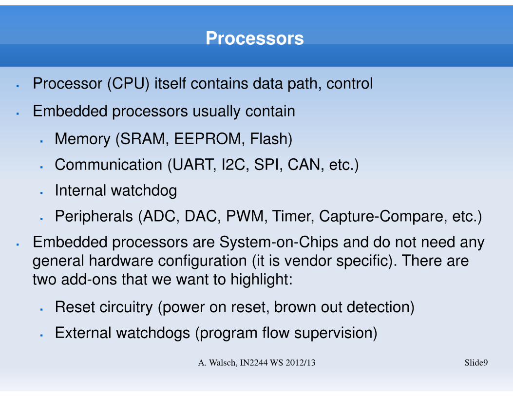
� Processor (CPU) itself contains data path, control
� Embedded processors usually contain
� Memory (SRAM, EEPROM, Flash)
� Communication (UART, I2C, SPI, CAN, etc.)
� Internal watchdog
� Peripherals (ADC, DAC, PWM, Timer, Capture-Compare, etc.)
� Embedded processors are System-on-Chips and do not need any
general hardware configuration (it is vendor specific). There are
two add-ons that we want to highlight:
� Reset circuitry (power on reset, brown out detection)
� External watchdogs (program flow supervision)
CPU
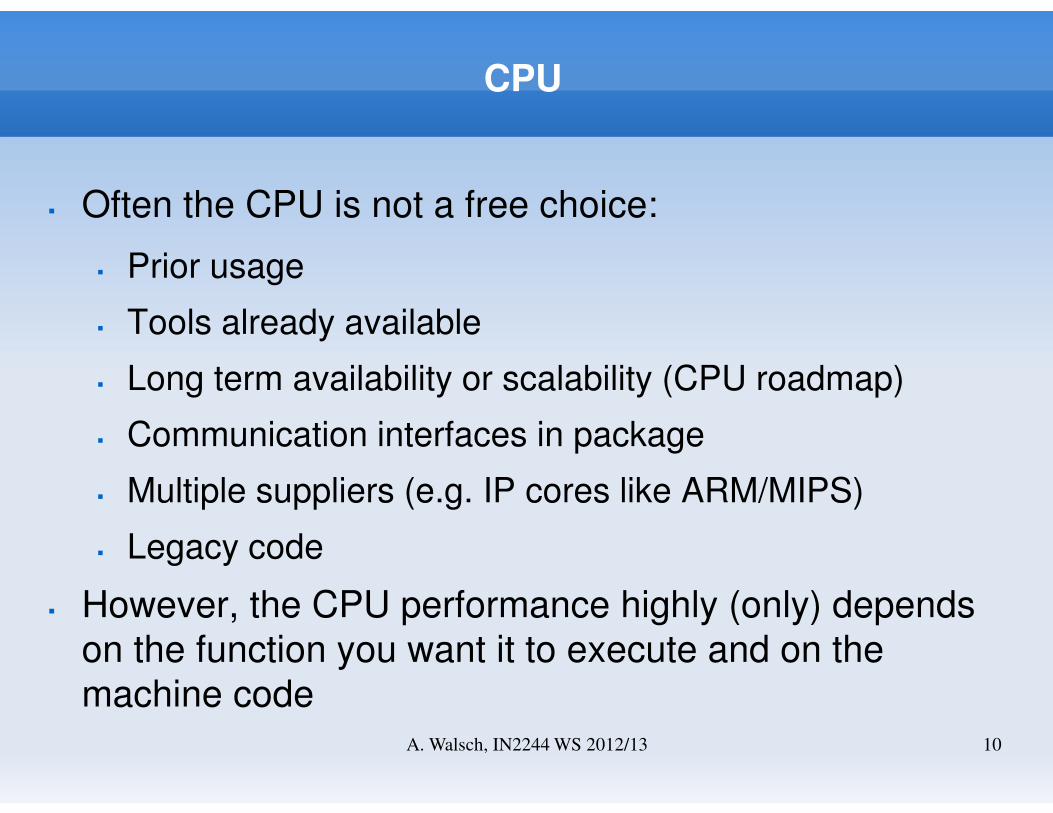
� Often the CPU is not a free choice:
� Prior usage
� Tools already available
� Long term availability or scalability (CPU roadmap)
� Communication interfaces in package
� Multiple suppliers (e.g. IP cores like ARM/MIPS)
� Legacy code
� However, the CPU performance highly (only) depends
on the function you want it to execute and on the
machine codeA. Walsch, IN2244 WS 2012/13 10
Memory
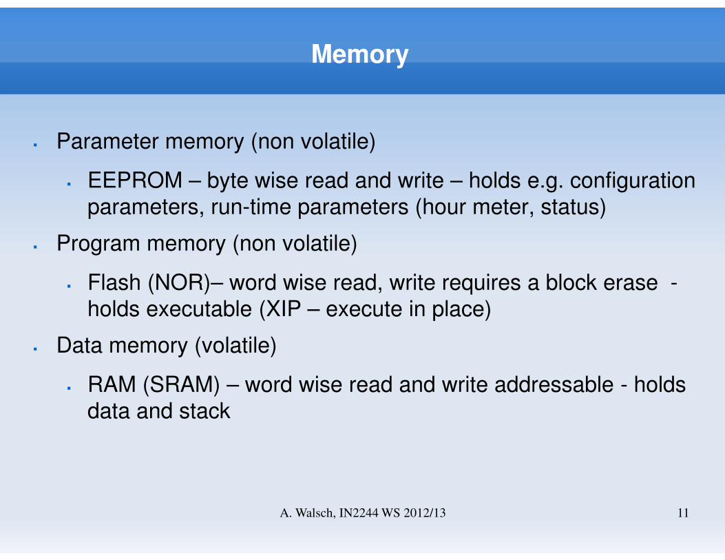
� Parameter memory (non volatile)
� EEPROM – byte wise read and write – holds e.g. configuration
parameters, run-time parameters (hour meter, status)
� Program memory (non volatile)
� Flash (NOR)– word wise read, write requires a block erase -
holds executable (XIP – execute in place)
� Data memory (volatile)
� RAM (SRAM) – word wise read and write addressable - holds
data and stack
A. Walsch, IN2244 WS 2012/13 11
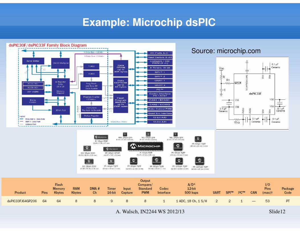
Example: Microchip dsPIC
Slide12A. Walsch, IN2244 WS 2012/13
Source: microchip.com
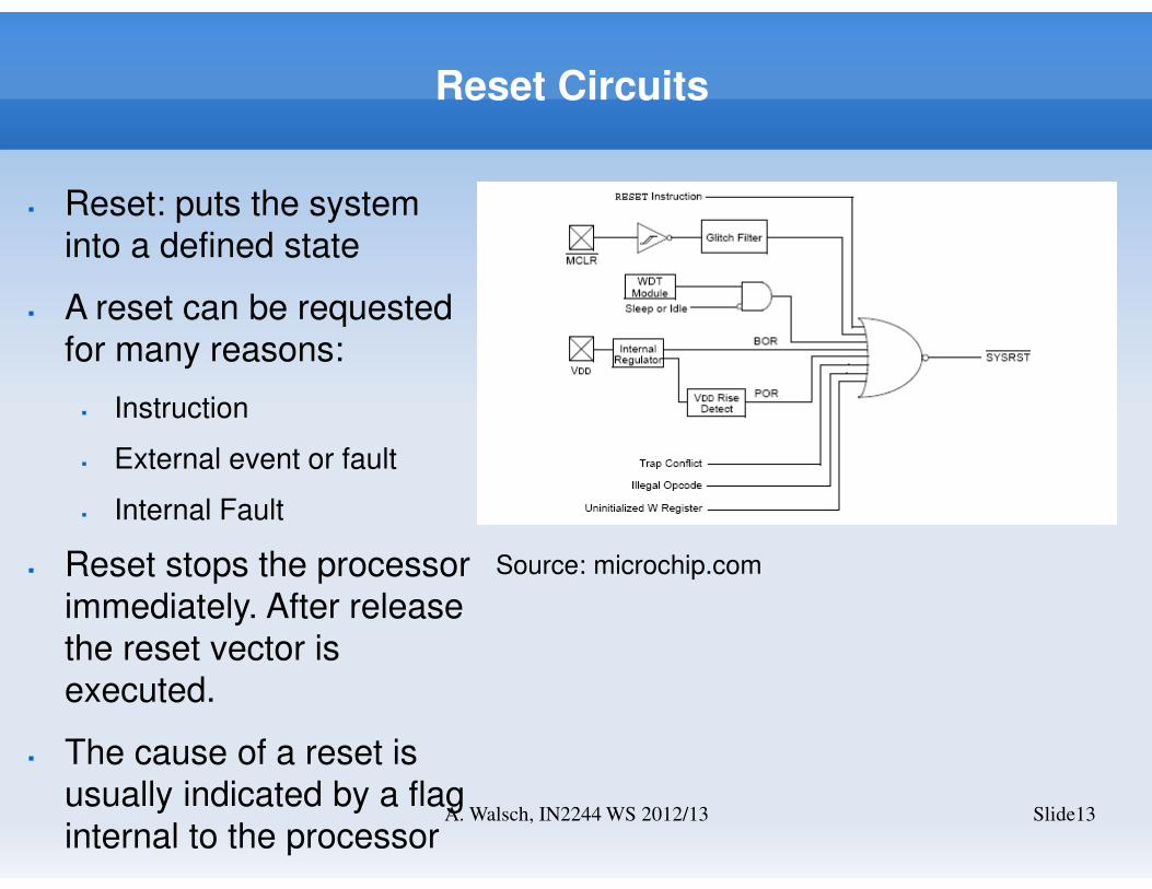
Reset Circuits
Slide13A. Walsch, IN2244 WS 2012/13
� Reset: puts the system
into a defined state
� A reset can be requested
for many reasons:
� Instruction
� External event or fault
� Internal Fault
� Reset stops the processor
immediately. After release
the reset vector is
executed.
� The cause of a reset is
usually indicated by a flag
internal to the processor
Source: microchip.com
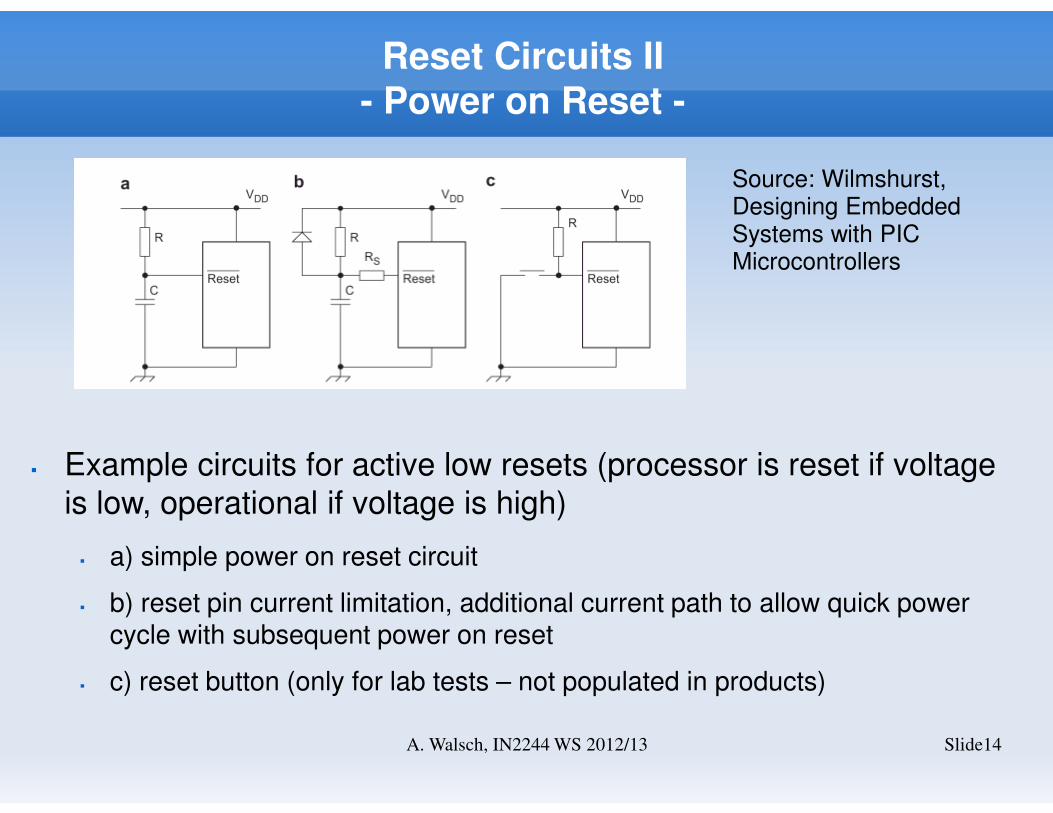
Reset Circuits II- Power on Reset -
Slide14A. Walsch, IN2244 WS 2012/13
Source: Wilmshurst, Designing Embedded Systems with PIC Microcontrollers
� Example circuits for active low resets (processor is reset if voltage
is low, operational if voltage is high)
� a) simple power on reset circuit
� b) reset pin current limitation, additional current path to allow quick power cycle with subsequent power on reset
� c) reset button (only for lab tests – not populated in products)
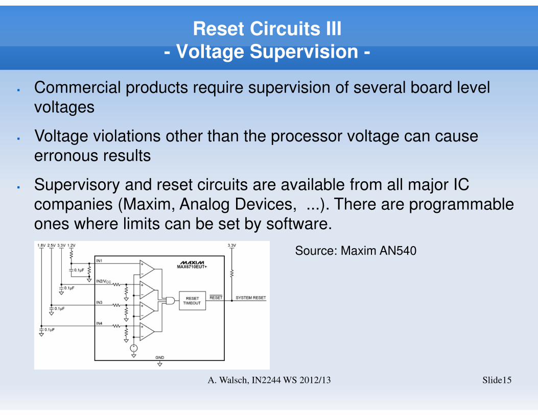
Reset Circuits III- Voltage Supervision -
Slide15A. Walsch, IN2244 WS 2012/13
� Commercial products require supervision of several board level
voltages
� Voltage violations other than the processor voltage can cause
erronous results
� Supervisory and reset circuits are available from all major IC
companies (Maxim, Analog Devices, ...). There are programmable
ones where limits can be set by software.
Source: Maxim AN540
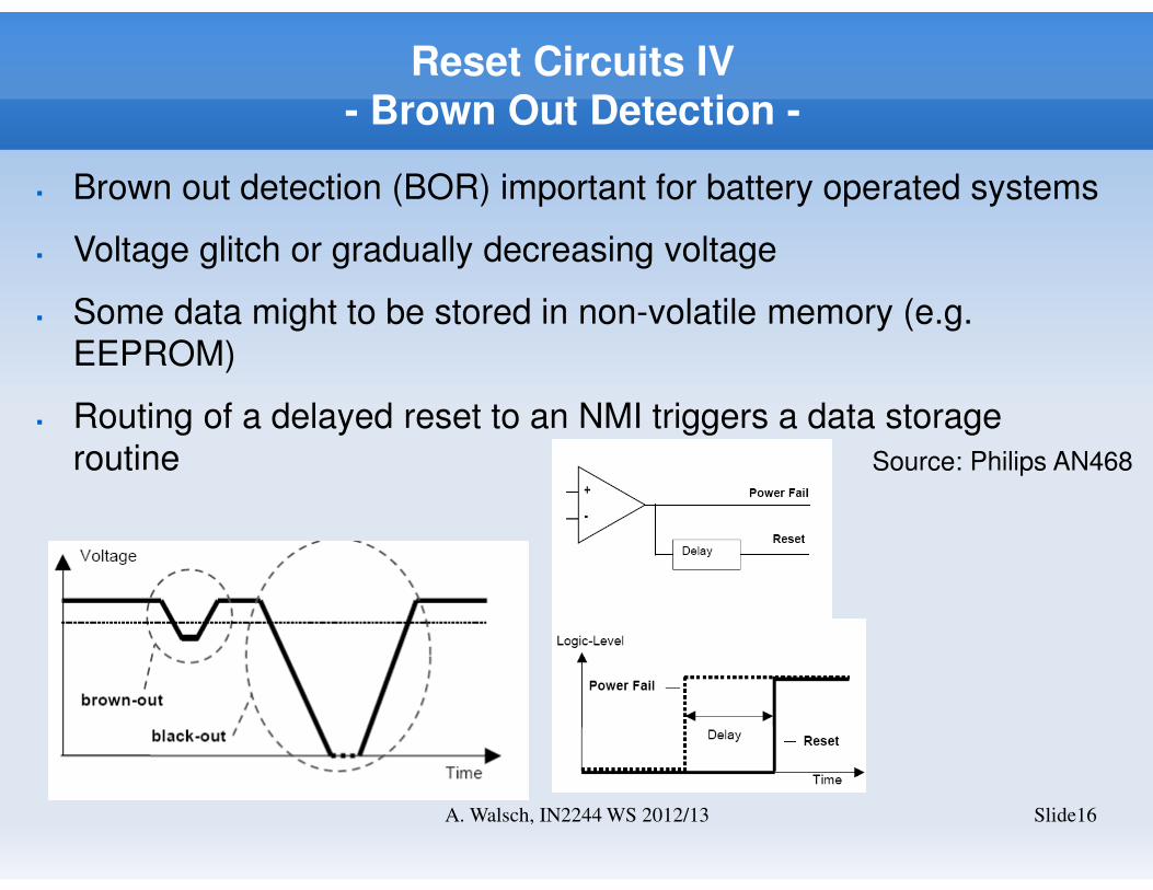
Reset Circuits IV- Brown Out Detection -
Slide16A. Walsch, IN2244 WS 2012/13
� Brown out detection (BOR) important for battery operated systems
� Voltage glitch or gradually decreasing voltage
� Some data might to be stored in non-volatile memory (e.g.
EEPROM)
� Routing of a delayed reset to an NMI triggers a data storage
routine Source: Philips AN468
Watchdog Circuits
Slide17A. Walsch, IN2244 WS 2012/13
� A watchdog timer is a supervisory component which must be
triggered in regular intervals in order to avoid system reset
� Embedded processors usually come with internal watchdog
circuits.
� A failure mode (drift) of the oscillator (account for in FMEA) makes
a second external one with a separate clock source highly
advisable for robust systems.
� Internal watchdogs can be disabled accidentally by software
� Set and reset the watchdog in different parts of the software to
disallow stuck-at watchdog pulse loops
Watchdog Circuits II
Slide18A. Walsch, IN2244 WS 2012/13
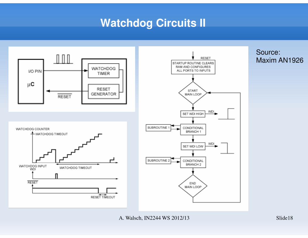
Source: Maxim AN1926
Watchdog Circuits III- 1oo1D architecture -
Slide19A. Walsch, IN2244 WS 2012/13
� Embedded processor is supervised by an external watchdog and a
separate independent output is provided
� A single channel can fail dangerously and safely: λd, λs
� Dangeros failures (different failure modes) can be detected and
undetected: λdd, λdu
� Dangerous detected failures are „converted“ into safe failures (the
response is the safe state).
� An external watchdog detects deviations in software execution
sequence and timeliness and thus detects possible dangerous
failures.
Watchdog Circuits IV
Slide20A. Walsch, IN2244 WS 2012/13
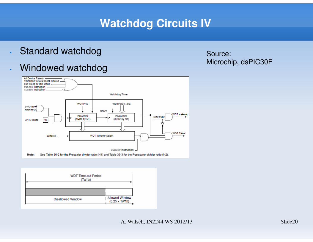
� Standard watchdog
� Windowed watchdog
Source: Microchip, dsPIC30F
Reconfigurable Electronics
Slide21A. Walsch, IN2244 WS 2012/13
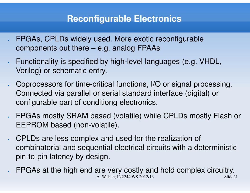
� FPGAs, CPLDs widely used. More exotic reconfigurable
components out there – e.g. analog FPAAs
� Functionality is specified by high-level languages (e.g. VHDL,
Verilog) or schematic entry.
� Coprocessors for time-critical functions, I/O or signal processing.
Connected via parallel or serial standard interface (digital) or
configurable part of conditiong electronics.
� FPGAs mostly SRAM based (volatile) while CPLDs mostly Flash or
EEPROM based (non-volatile).
� CPLDs are less complex and used for the realization of
combinatorial and sequential electrical circuits with a deterministic
pin-to-pin latency by design.
� FPGAs at the high end are very costly and hold complex circuitry.
Reconfigurable Electronics II
Slide22A. Walsch, IN2244 WS 2012/13
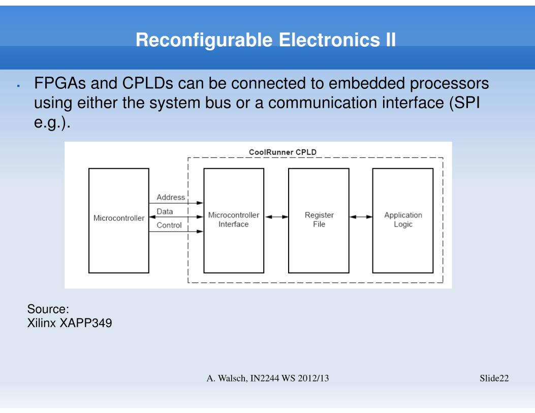
� FPGAs and CPLDs can be connected to embedded processors
using either the system bus or a communication interface (SPI
e.g.).
Source: Xilinx XAPP349
Analog Electronics
Slide23A. Walsch, IN2244 WS 2012/13
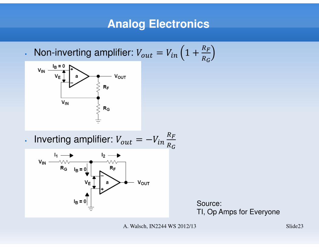
� Non-inverting amplifier: ���� = ��� 1 +�
�
� Inverting amplifier: ���� = −����
�
Source: TI, Op Amps for Everyone
Analog Electronics II
Slide24A. Walsch, IN2244 WS 2012/13
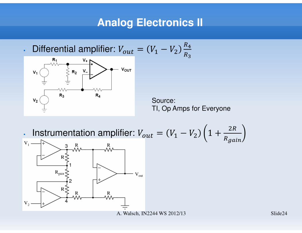
� Differential amplifier: ���� = �� − ���
�
� Instrumentation amplifier: ���� = �� − �� 1 +�
����
Source: TI, Op Amps for Everyone
Analog Electronics III
Slide25A. Walsch, IN2244 WS 2012/13
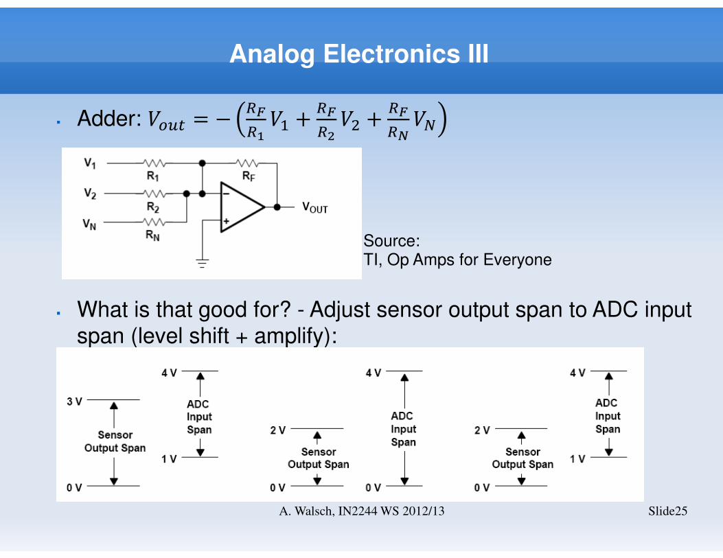
� Adder: ���� = −�
��� +
�
��� +
�
���
� What is that good for? - Adjust sensor output span to ADC input
span (level shift + amplify):
Source: TI, Op Amps for Everyone
Mixed-signal Electronics- ADC -
Slide26A. Walsch, IN2244 WS 2012/13
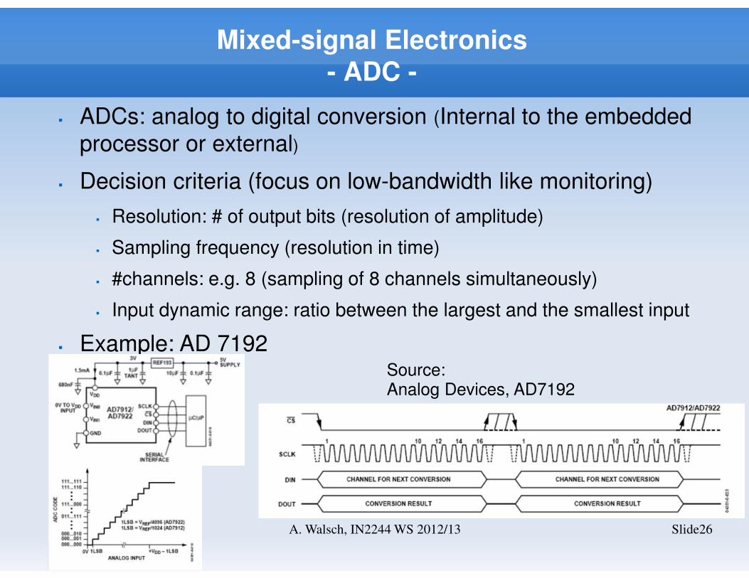
� ADCs: analog to digital conversion (Internal to the embedded
processor or external)
� Decision criteria (focus on low-bandwidth like monitoring)
� Resolution: # of output bits (resolution of amplitude)
� Sampling frequency (resolution in time)
� #channels: e.g. 8 (sampling of 8 channels simultaneously)
� Input dynamic range: ratio between the largest and the smallest input
� Example: AD 7192Source: Analog Devices, AD7192
Mixed-signal Electronics- DAC -
Slide27A. Walsch, IN2244 WS 2012/13
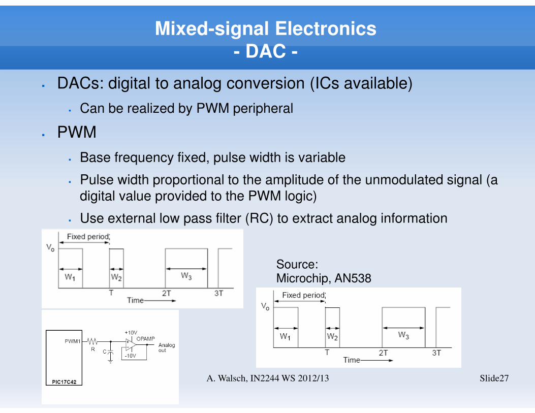
� DACs: digital to analog conversion (ICs available)
� Can be realized by PWM peripheral
� PWM
� Base frequency fixed, pulse width is variable
� Pulse width proportional to the amplitude of the unmodulated signal (a digital value provided to the PWM logic)
� Use external low pass filter (RC) to extract analog information
Source: Microchip, AN538
Mixed-signal Electronics
Slide28A. Walsch, IN2244 WS 2012/13
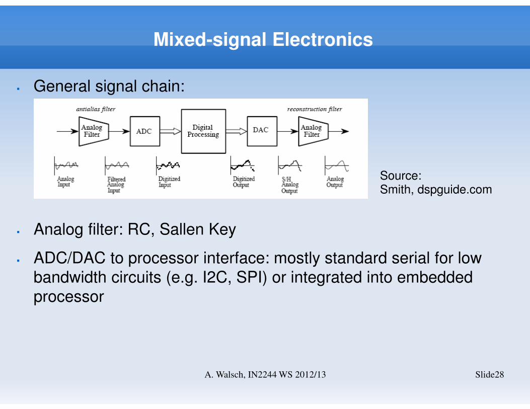
� General signal chain:
� Analog filter: RC, Sallen Key
� ADC/DAC to processor interface: mostly standard serial for low
bandwidth circuits (e.g. I2C, SPI) or integrated into embedded
processor
Source: Smith, dspguide.com
Communication- UART -
Slide29A. Walsch, IN2244 WS 2012/13
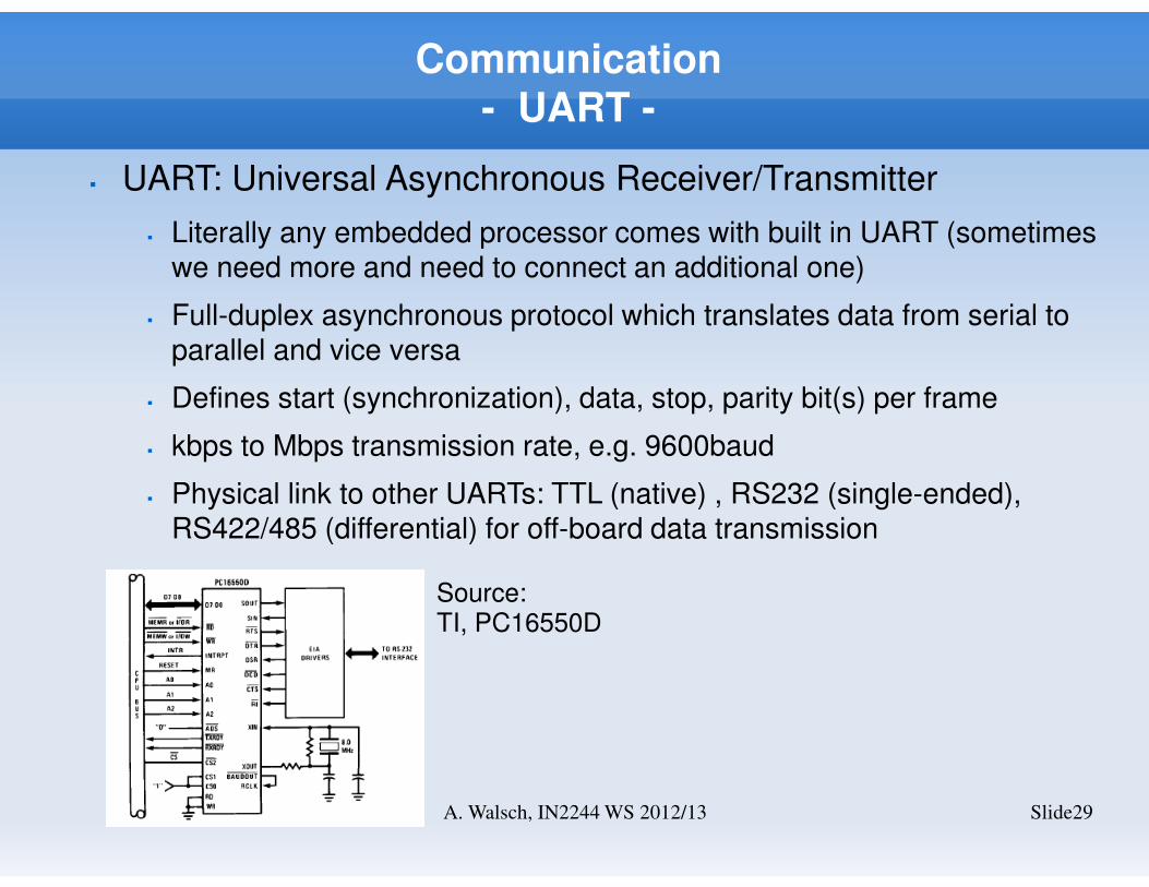
� UART: Universal Asynchronous Receiver/Transmitter
� Literally any embedded processor comes with built in UART (sometimes we need more and need to connect an additional one)
� Full-duplex asynchronous protocol which translates data from serial to parallel and vice versa
� Defines start (synchronization), data, stop, parity bit(s) per frame
� kbps to Mbps transmission rate, e.g. 9600baud
� Physical link to other UARTs: TTL (native) , RS232 (single-ended), RS422/485 (differential) for off-board data transmission
Source: TI, PC16550D
Communication- RS232 -
Slide30A. Walsch, IN2244 WS 2012/13
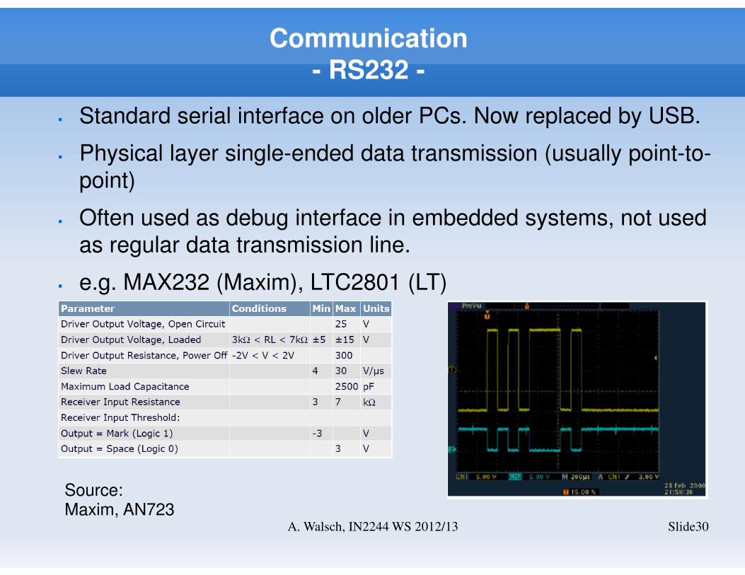
� Standard serial interface on older PCs. Now replaced by USB.
� Physical layer single-ended data transmission (usually point-to-
point)
� Often used as debug interface in embedded systems, not used
as regular data transmission line.
� e.g. MAX232 (Maxim), LTC2801 (LT)
Source: Maxim, AN723
Communication- RS422/485 -
Slide31A. Walsch, IN2244 WS 2012/13
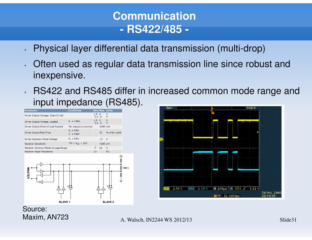
� Physical layer differential data transmission (multi-drop)
� Often used as regular data transmission line since robust and
inexpensive.
� RS422 and RS485 differ in increased common mode range and
input impedance (RS485).
Source: Maxim, AN723
Communication- I2C -
Slide32A. Walsch, IN2244 WS 2012/13
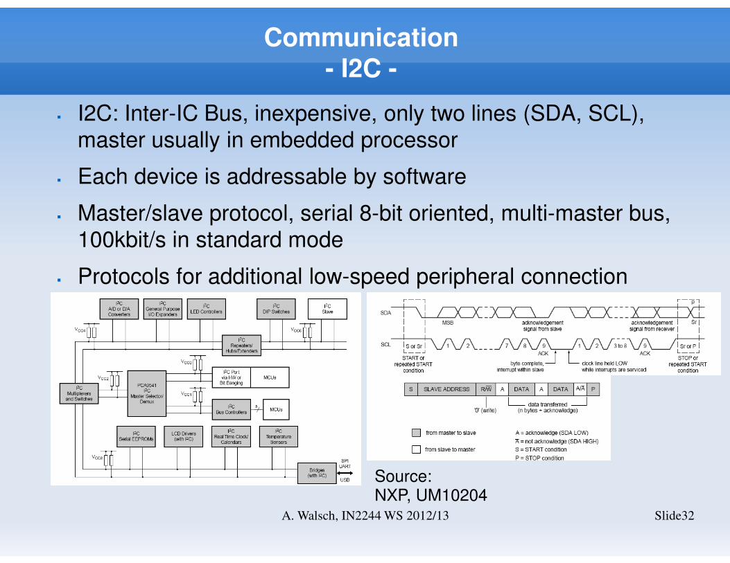
� I2C: Inter-IC Bus, inexpensive, only two lines (SDA, SCL),
master usually in embedded processor
� Each device is addressable by software
� Master/slave protocol, serial 8-bit oriented, multi-master bus,
100kbit/s in standard mode
� Protocols for additional low-speed peripheral connection
(EEPROM, ADC/DAC, …)
Source: NXP, UM10204
Communication- SPI -
Slide33A. Walsch, IN2244 WS 2012/13
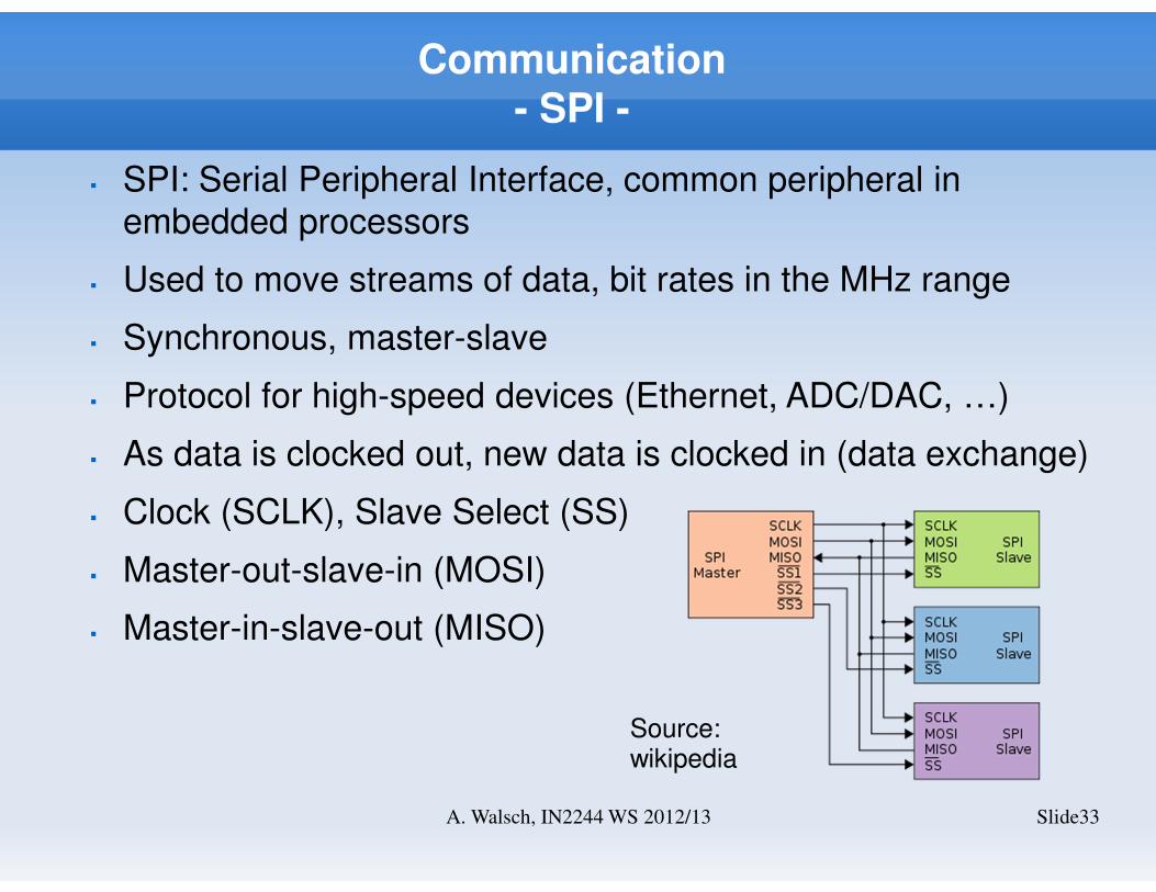
� SPI: Serial Peripheral Interface, common peripheral in
embedded processors
� Used to move streams of data, bit rates in the MHz range
� Synchronous, master-slave
� Protocol for high-speed devices (Ethernet, ADC/DAC, …)
� As data is clocked out, new data is clocked in (data exchange)
� Clock (SCLK), Slave Select (SS)
� Master-out-slave-in (MOSI)
� Master-in-slave-out (MISO)
Source: wikipedia
Communication- Current Loop (long distance)-
Slide34A. Walsch, IN2244 WS 2012/13
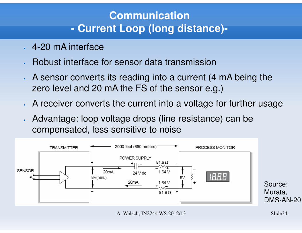
� 4-20 mA interface
� Robust interface for sensor data transmission
� A sensor converts its reading into a current (4 mA being the
zero level and 20 mA the FS of the sensor e.g.)
� A receiver converts the current into a voltage for further usage
� Advantage: loop voltage drops (line resistance) can be
compensated, less sensitive to noise
Source: Murata, DMS-AN-20
Communication- CAN -
Slide35A. Walsch, IN2244 WS 2012/13
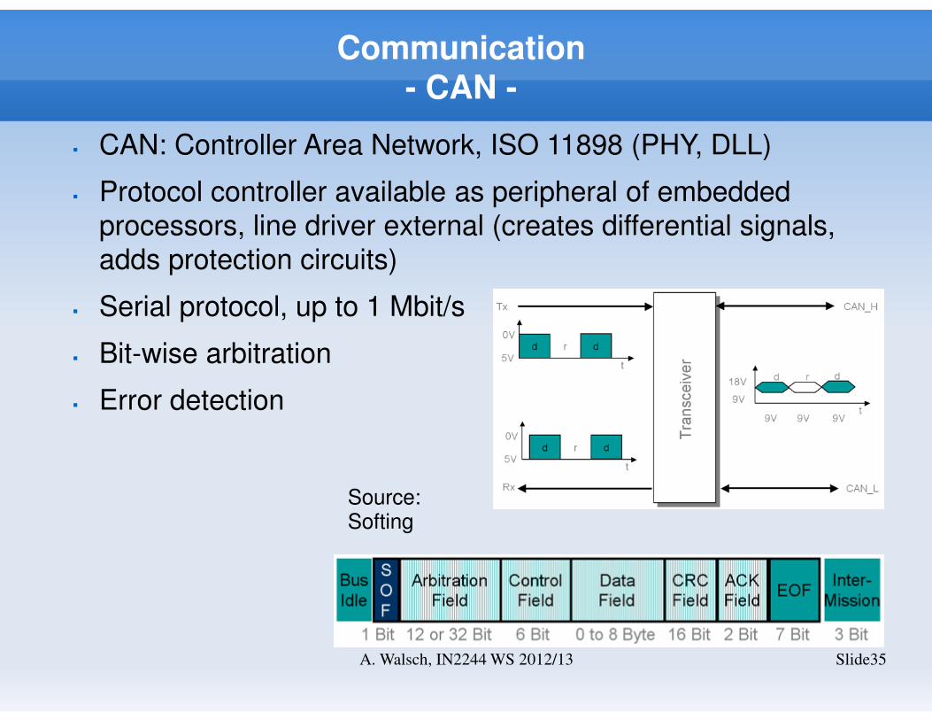
� CAN: Controller Area Network, ISO 11898 (PHY, DLL)
� Protocol controller available as peripheral of embedded
processors, line driver external (creates differential signals,
adds protection circuits)
� Serial protocol, up to 1 Mbit/s
� Bit-wise arbitration
� Error detection
Source: Softing
Communication- error detection -
Slide36A. Walsch, IN2244 WS 2012/13
Address
8 bitData – 128 bit CRC – 16 bit
payload
transmitted data
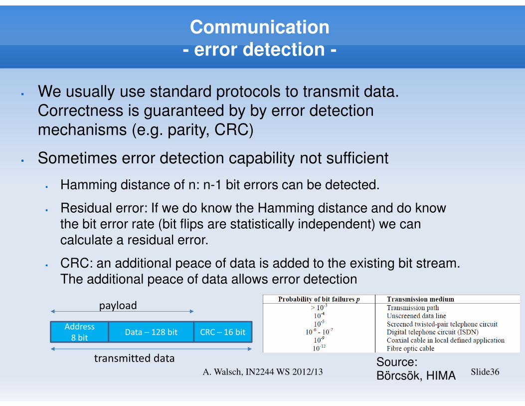
� We usually use standard protocols to transmit data.
Correctness is guaranteed by by error detection
mechanisms (e.g. parity, CRC)
� Sometimes error detection capability not sufficient
� Hamming distance of n: n-1 bit errors can be detected.
� Residual error: If we do know the Hamming distance and do know the bit error rate (bit flips are statistically independent) we can calculate a residual error.
� CRC: an additional peace of data is added to the existing bit stream. The additional peace of data allows error detection
Source: Börcsök, HIMA
Questions?
Slide37A. Walsch, IN2244 WS 2012/13


![⃝[charles stephenson, chris taylor] the channels](https://img.pdfslide.tips/doc/110x75/568ca9bb1a28ab186d9eb5f4/charles-stephenson-chris-taylor-the-channels.jpg)