Embed Size (px)
Citation preview
7/27/2019 Dual Band UWB
http://slidepdf.com/reader/full/dual-band-uwb 1/4
Circuit Analysis of Electromagnetic Band Gap (EBG)
Structures
S. Palreddy2,3
, A.I. Zaghloul*1, 2
1US Army Research Laboratory, Adelphi, MD 20783, USA
[email protected] 2Virginia Tech, VA 24061, USA
3Microwave Engineering Corporation, North Andover, MA 01845, USA
Abstract —This paper presents a circuit analysis of
electromagnetic band gap structures (EBG). Microwave
transmission line theory is used to accurately analyze EBG
structures. The results of this analysis are compared with
previously published results, including more time-intensive full-wave analysis result, and this analysis is validated. The analysis
applies to any type of EBG structure, including conventional
periodic EBGs and progressive-dimensions EBG with broadband
response.
I. I NTRODUCTION
Electromagnetic band gap (EBG) structures are usually
periodic structures [1], [2], [3], [4]. EBG structures areequivalent to a magnetic surface at the frequency of resonance
and thus have very high surface impedance; this makes a
tangential current element close to the EBG structure
equivalent to two current elements oriented in the same
direction without the EBG structure. This helps enhance the
forward radiation instead of completely cancelling it, as
indicated by the image theory. This makes the EBG structures
useful when mounting an antenna close to ground, provided
the antenna’s currents are parallel to the EBG surface.
EBG structures are equivalent to a tank circuit. Equations
(1) through (3) give the impedance, frequency of resonance
and bandwidth respectively of an EBG structure [1], [2], [3],
[4]. The bandwidth of the EBG structure is defined as the
band of frequencies where the reflection phase is between
+900 to –90
0.
2
0
1
L j Z s
(1)
LC
1
0
(2)
C
L BW
120
1
(3)
II. A NALYSIS
Assuming a plane wave incidence and using transmission
line theory, the reflection phase of the EBG structure can be
found. Transmission line theory is used to find the complex
reflection coefficient from the EBG surface and then the
reflection phase is found. The reflection coefficient from a
load ZL in a transmission line with a characteristic impedance
of Z0 is given by:
(4)
The reflection coefficient from a perfect electric conductor
(PEC) is -1. The reflection coefficient from a perfect magnetic
conductor (PMC) is +1. In both cases the magnitude is the
same, but the phase is different. So, to accurately analyse the
reflection phase, we need to come up with an approach that
does not change the magnitude of the reflection with
frequency, but changes the reflection phase with frequency.
How can this be done when the reflection coefficient has
difference of impedances in the numerator and sum of the
impedances in the denominator? We know that a complex
number and its complex conjugate have the same magnitude.
Free space has real impedance, so we need to model the EBG
structure as pure imaginary surface impedance. This is a goodapproximation as EBG structures have low loss, which
implies the real part of the surface impedance is very small
compared to imaginary part. This analysis assumes that the
EBG structure is lossless. Let Zs be the surface impedance of
the EBG structure. The reflection coefficient and the
reflection phase can be calculated as:
(5)
0
0
Z Z
Z Z
L
L
jX Z s
Copyright 2013 IEICE
Proceedings of the "2013 International Symposium on Electromagnetic Theory"
21AM1D-01
67
7/27/2019 Dual Band UWB
http://slidepdf.com/reader/full/dual-band-uwb 2/4
0
0
s
s
Z
Z (6)
1 (7)
0
1tan2
x
(8)
The bandwidth of EBG structure is defined as the band
where the reflection phase is between +900 to -90
0. Using this
with equation (8), we can find the required conditions on the
surface impedance.00
9090
0
0
10090tan218090
x
0
0
1090tan2270
x
0
0
1045tan135
x
11
0
X
00 X (9)
Equation (9) shows the required conditions to operate in the
bandwidth of the EBG. Figure 1 shows the relationship
between surface impedance and the reflection phase.
Fig. 1: Relationship between surface impedance and
reflection phase of EBG structure.
The band edges of the EBG structure, as shown in Figure 1,
are where the reflection phase is +900 (where the surface
0) and -900 (where the surface
impedance is equal to -0 1 be the radian frequency
0
2
0
1
L j Z s
jX Z s
2
0
1
10
1
L
0
1
2
0
1
1
L
0
1
2
02
1
2
0
L (10)
-
2
0
2
20
1
L
0
2
2
0
2
1
L
0
2
2
02
2
2
0
L (11)
Subtracting equations (10) and (11) we get:
21
0
2
02
1
2
2
L
021
0
2
0
1221
L
0
0
2
0
1221
L
1 2) cannot be zero, so the only possible solution
is:
0
2
0
12
L
Where LC
10
Bandwidth =
C
L L
00
0
0
12 1
(12)
This analysis can be performed for any desired reflection
phase (using equation 8) to get the required conditions on thesurface impedance of the EBG structure. This paper uses the
reflection phase condition to be within +900 to -90
0 as this
condition is widely used in defining the bandwidth of EBG
structures, and these results are used in comparing the
previously published results. This analysis represents anyEBG structure as surface impedance and gives the required
conditions on the surface impedance to get the desired range
of reflection phase. Different types of EBG structures differ in
Proceedings of the "2013 International Symposium on Electromagnetic Theory"
68
7/27/2019 Dual Band UWB
http://slidepdf.com/reader/full/dual-band-uwb 3/4
the way they are implemented to get the desired surface
impedance. Thus this analysis applies to any EBG structure.
III. VALIDATION
We see that equation (12) agrees with the published
bandwidth given in equation (3), hence validating this analysis.
Using this analysis the reflection phase of a uniform EBG
structure is found using Matlab [6] and compared with the
published results in [5], which were obtained usingFDTD/PBC for the case where patch width is 3 mm, gap
between the patches is 0.5 mm, via height is 1 mm and the
relative permittivity of the board is 2.20. All the dimensions in
figures 2 through 5 are given as a fraction of wavelength at 12
GHz. To find the surface impedance, closed form equations
for the capacitance and inductance of the EBG structure are
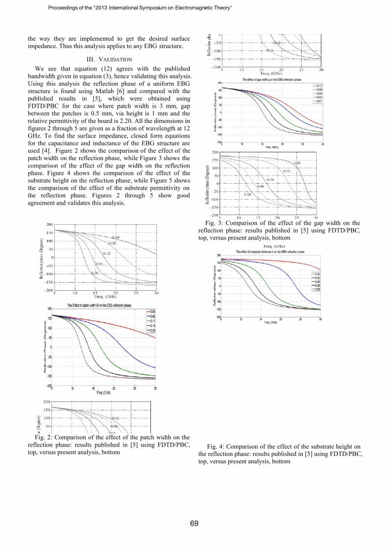
used [4]. Figure 2 shows the comparison of the effect of the
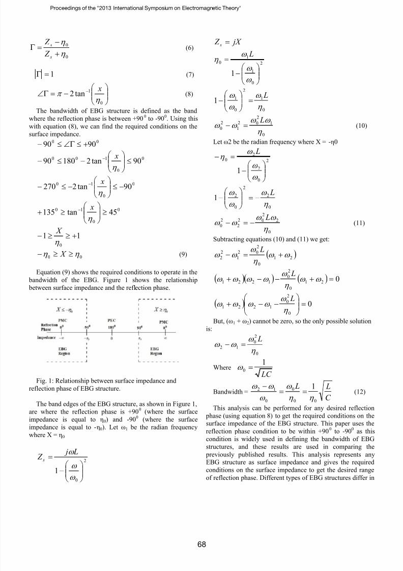
patch width on the reflection phase, while Figure 3 shows the
comparison of the effect of the gap width on the reflection
phase. Figure 4 shows the comparison of the effect of the
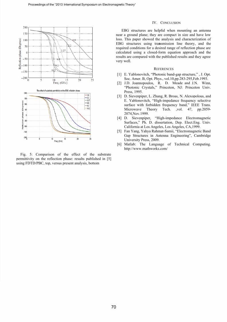
substrate height on the reflection phase, while Figure 5 shows
the comparison of the effect of the substrate permittivity on
the reflection phase. Figures 2 through 5 show good
agreement and validates this analysis.
Fig. 2: Comparison of the effect of the patch width on the
reflection phase: results published in [5] using FDTD/PBC,top, versus present analysis, bottom
Fig. 3: Comparison of the effect of the gap width on the
reflection phase: results published in [5] using FDTD/PBC,top, versus present analysis, bottom
Fig. 4: Comparison of the effect of the substrate height onthe reflection phase: results published in [5] using FDTD/PBC,
top, versus present analysis, bottom
Proceedings of the "2013 International Symposium on Electromagnetic Theory"
69
7/27/2019 Dual Band UWB
http://slidepdf.com/reader/full/dual-band-uwb 4/4
Fig. 5: Comparison of the effect of the substrate
permittivity on the reflection phase: results published in [5]
using FDTD/PBC, top, versus present analysis, bottom
IV. CONCLUSION
EBG structures are helpful when mounting an antenna
near a ground plane; they are compact in size and have low
loss. This paper showed the analysis and characterization of
EBG structures using transmission line theory, and the
required conditions for a desired range of reflection phase are
calculated using a closed-form equation approach and the
results are compared with the published results and they agreevery well.
R EFERENCES
[1] E. Yablonovitch, “Photonic band-gap structure,” , J. Opt.
Soc. Amer. B, Opt. Phys., vol.10,pp.283-295,Feb.1993.
[2] J.D. Joannopoulos, R. D. Meade and J.N. Winn,
“Photonic Crystals,” Princeton, NJ: Princeton Univ.
Press, 1995.
[3] D. Sievenpiper, L. Zhang, R. Broas, N. Alexopolous, and
E. Yablonovitch, “High-impedance frequency selective
surface with forbidden frequency band,” IEEE Trans.
Microwave Theory Tech. ,vol. 47, pp.2059-
2074,Nov.1999.[4] D. Sievenpiper, “High-impedance Electromagnetic
Surfaces,” Ph. D. dissertation, Dep. Elect.Eng. Univ.
California at Los Angeles, Los Angeles, CA,1999.
[5] Fan Yang, Yahya Rahmat-Samii, “Electromagnetic Band
Gap Structures in Antenna Engineering”, CambridgeUniversity Press, 2009.
[6] Matlab: The Language of Technical Computing.
http://www.mathworks.com/
Proceedings of the "2013 International Symposium on Electromagnetic Theory"
70