Embed Size (px)
Citation preview
Dual Connectivity in LTE
資策會 智通所 魏嘉宏
1

魏嘉宏 (Chia-Hung Wei) • 現職:資訊工業策進會/智慧網通系統研究所/標準組/正工程師 • 2010/9~2013/1 國立台灣科技大學 電子工程系 博士 畢
2
Outline • Background • Scenario • Architecture • User Plane feature • Control Plane feature
3
Outline • Background • Scenario • Architecture • User Plane feature • Control Plane feature
4
Background (1/2) • Small cells are:
– Becoming a promising technology to meet ever increasing traffic capacity and data rate demand.
– Typically deployed as hotspots within macro cell coverage.
• 3GPP progress of: – Study item (SI): LTE small cell enhancement (SCE) – higher layer aspects [1]
5
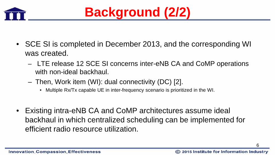
Background (2/2)
• SCE SI is completed in December 2013, and the corresponding WI was created. – LTE release 12 SCE SI concerns inter-eNB CA and CoMP operations
with non-ideal backhaul. – Then, Work item (WI): dual connectivity (DC) [2].
• Multiple Rx/Tx capable UE in inter-frequency scenario is prioritized in the WI.
• Existing intra-eNB CA and CoMP architectures assume ideal
backhaul in which centralized scheduling can be implemented for efficient radio resource utilization.
6
Challenges For inter-eNB CA and CoMP with non-ideal backhaul, distributed resource allocation and coordination have to be relied upon and new challenges emerge: • Efficient radio resource utilization across eNBs • Mobility robustness • Increased signalling load • UL/DL imbalance between macro and small cells
7
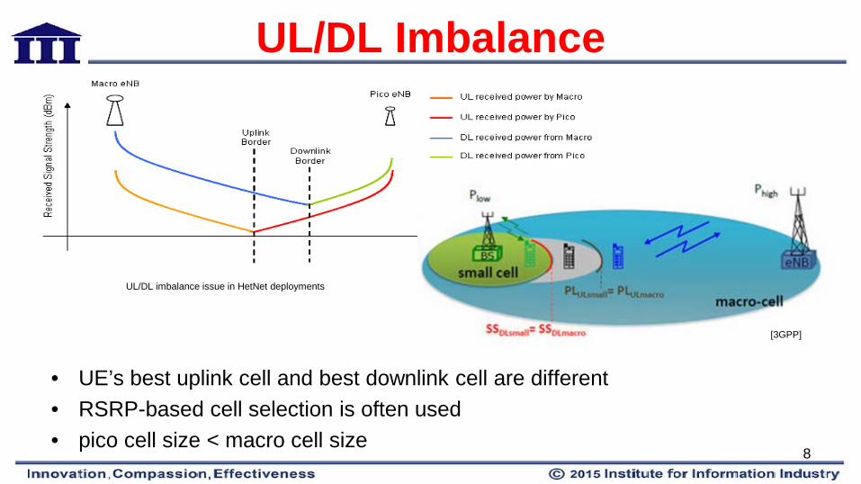
UL/DL Imbalance
• UE’s best uplink cell and best downlink cell are different • RSRP-based cell selection is often used • pico cell size < macro cell size
[3GPP]
UL/DL imbalance issue in HetNet deployments
8
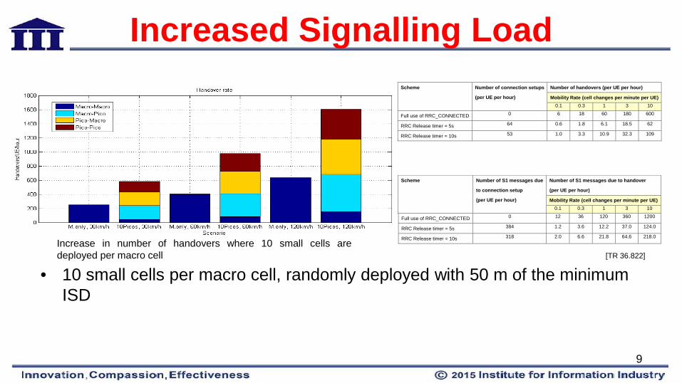
Increased Signalling Load
• 10 small cells per macro cell, randomly deployed with 50 m of the minimum ISD
Scheme Number of connection setups
(per UE per hour)
Number of handovers (per UE per hour)
Mobility Rate (cell changes per minute per UE) 0.1 0.3 1 3 10
Full use of RRC_CONNECTED 0 6 18 60 180 600
RRC Release timer = 5s 64 0.6 1.8 6.1 18.5 62
RRC Release timer = 10s 53 1.0 3.3 10.9 32.3 109
Scheme Number of S1 messages due
to connection setup
(per UE per hour)
Number of S1 messages due to handover
(per UE per hour)
Mobility Rate (cell changes per minute per UE) 0.1 0.3 1 3 10
Full use of RRC_CONNECTED 0 12 36 120 360 1200
RRC Release timer = 5s 384 1.2 3.6 12.2 37.0 124.0
RRC Release timer = 10s 318 2.0 6.6 21.8 64.6 218.0
[TR 36.822]
Increase in number of handovers where 10 small cells are deployed per macro cell
9
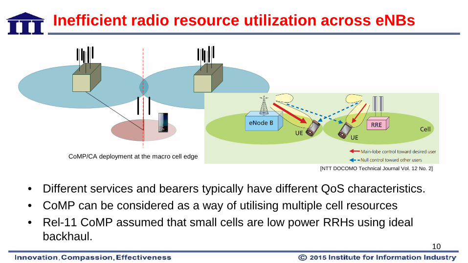
Inefficient radio resource utilization across eNBs
• Different services and bearers typically have different QoS characteristics. • CoMP can be considered as a way of utilising multiple cell resources • Rel-11 CoMP assumed that small cells are low power RRHs using ideal
backhaul.
[NTT DOCOMO Technical Journal Vol. 12 No. 2]
CoMP/CA deployment at the macro cell edge
10
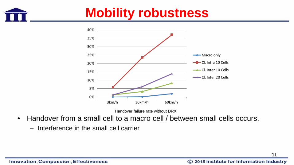
• Handover from a small cell to a macro cell / between small cells occurs. – Interference in the small cell carrier
0%
5%
10%
15%
20%
25%
30%
35%
40%
3km/h 30km/h 60km/h
Macro only
Cl. Intra 10 Cells
Cl. Inter 10 Cells
Cl. Inter 20 Cells
Mobility robustness
Handover failure rate without DRX
11
Outline • Background • Scenario • Architecture • User Plane feature • Control Plane feature
12
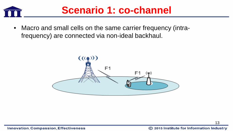
Scenario 1: co-channel • Macro and small cells on the same carrier frequency (intra-
frequency) are connected via non-ideal backhaul.
13
Challenges of Scenario #1 1. Mobility robustness: In particular increased HOF/RLF upon mobility from pico to
macro cells 2. UL/DL imbalance between macro and small cells; 3. Increased signalling load (e.g., to CN) due to frequent handover 4. Difficult to improve per-user throughput by utilizing radio resources in more than
one eNB 5. Network planning and configuration effort
14
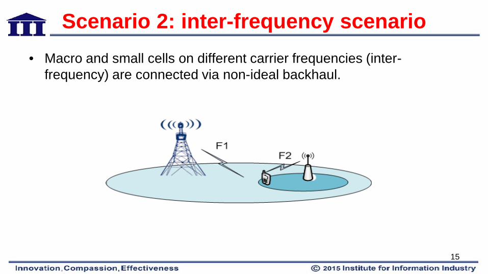
Scenario 2: inter-frequency scenario • Macro and small cells on different carrier frequencies (inter-
frequency) are connected via non-ideal backhaul.
15
Challenges of Scenario #2 1.Mobility robustness 2.UL/DL imbalance between macro and small cells 3.Increased signalling load (e.g., to CN) due to frequent handover 4.Difficult to improve per-user throughput by utilizing radio resources in more than one eNB 5.Network planning and configuration effort
16
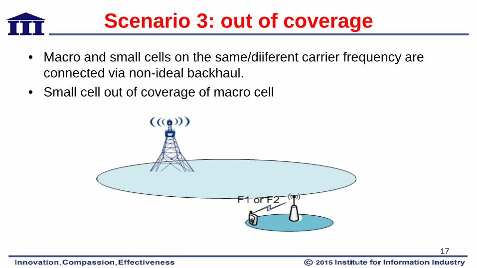
Scenario 3: out of coverage • Macro and small cells on the same/diiferent carrier frequency are
connected via non-ideal backhaul. • Small cell out of coverage of macro cell
17

Challenges of Scenario #3 1.Mobility robustness 2.Increased signalling load (e.g., to CN) due to frequent handover 3.Network planning and configuration effort
18
Potential Solution
Dual connectivity
19

Dual Connectivity • Dual Connectivity (DC) operation:
– Multiple RX/TX UE in RRC_CONNECTED – Utilise radio resources provided by two distinct schedulers – Schedulers located in two eNBs – Two eNBs connected via a non-ideal backhaul over the X2 interface.
• Enhancing small cells by dual connectivity:
– Increased UE throughput especially for cell edge UEs – Mobility robustness enhancement – Reducing signaling overhead towards the core due to frequent handover.
20

Outline • Background • Scenario • Architecture • User Plane feature • Control Plane feature
21

Architecture • User plane architecture
– Options for splitting the U-Plane data: • Option 1: S1-U also terminates in SeNB • Option 2: S1-U terminates in MeNB, no bearer split in RAN • Option 3: S1-U terminates in MeNB, bearer split in RAN
22
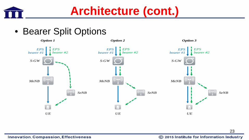
Architecture (cont.) • Bearer Split Options
Option 3Option 1
MeNB
SeNB
EPS bearer #1
EPS bearer #2
UE
S-GW
Option 2
MeNB
SeNB
EPS bearer #1
EPS bearer #2
UE
S-GW
MeNB
EPS bearer #1
SeNB
EPS bearer #2
UE
S-GW
23
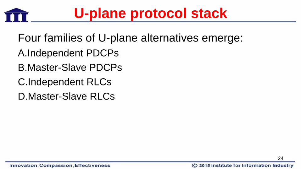
U-plane protocol stack Four families of U-plane alternatives emerge: A.Independent PDCPs B.Master-Slave PDCPs C.Independent RLCs D.Master-Slave RLCs
24
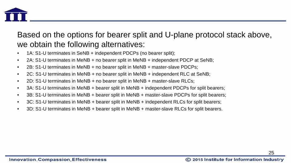
Based on the options for bearer split and U-plane protocol stack above, we obtain the following alternatives: • 1A: S1-U terminates in SeNB + independent PDCPs (no bearer split); • 2A: S1-U terminates in MeNB + no bearer split in MeNB + independent PDCP at SeNB; • 2B: S1-U terminates in MeNB + no bearer split in MeNB + master-slave PDCPs; • 2C: S1-U terminates in MeNB + no bearer split in MeNB + independent RLC at SeNB; • 2D: S1-U terminates in MeNB + no bearer split in MeNB + master-slave RLCs; • 3A: S1-U terminates in MeNB + bearer split in MeNB + independent PDCPs for split bearers; • 3B: S1-U terminates in MeNB + bearer split in MeNB + master-slave PDCPs for split bearers; • 3C: S1-U terminates in MeNB + bearer split in MeNB + independent RLCs for split bearers; • 3D: S1-U terminates in MeNB + bearer split in MeNB + master-slave RLCs for split bearers.
25
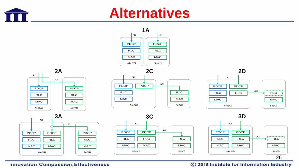
Alternatives
MeNB
PDCP
RLC
MAC
SeNB
PDCP
RLC
MAC
S1 S11A
MeNB
PDCP
RLC
MAC
SeNB
PDCP
RLC
MAC
S1
Xn
MeNB
PDCP
RLC
MAC
SeNB
PDCP
RLC
MAC
S1
Xn
MeNB
PDCP
RLC
MAC
SeNB
PDCP
RLC
MAC
S1
XnRLC
MeNB
PDCP
RLC
MAC
SeNB
PDCP
RLC
MAC
S1
Xn
PDCP
RLC
MAC
MeNB
PDCP
RLC
MAC
SeNB
PDCP
RLC
MAC
S1
Xn
RLC
MAC
MeNB
PDCP
RLC
MAC
SeNB
PDCP
RLC
MAC
S1
XnRLC
MAC
2A 2C 2D
3A 3C 3D
26

Comparison of U-plane data split options
• Alternative 1A and 3C are to be progressed to support U-plane data split options of Option 1and 3 in this study
Option 1 Option 2 Option 3
Per-user throughput enhancements
Lower gain is expected. Higher gain is expected.
Mobility robustness Can be achieved. Signalling load to CN Both SeNB and MeNB mobility
is visible to CN. Comparable to the macro only network.
Backhaul requirements No additional throughput requirement on backhaul of
MeNB
Not analysed The Xn interface has to offer the latency of 5-30 ms and
sufficient capacity.
27
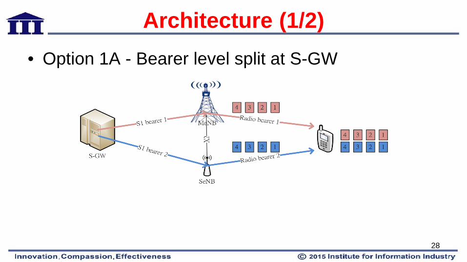
Architecture (1/2) • Option 1A - Bearer level split at S-GW
28
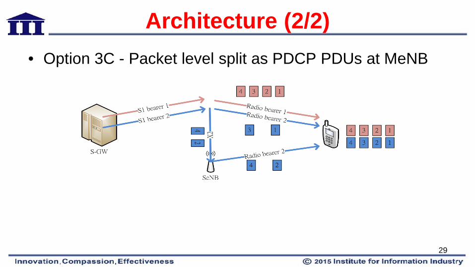
Architecture (2/2) • Option 3C - Packet level split as PDCP PDUs at MeNB
29
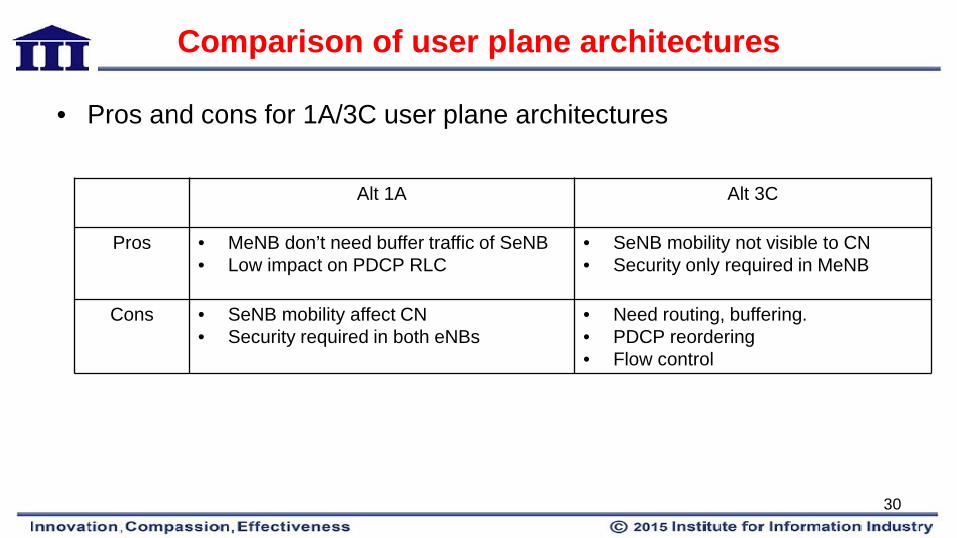
Comparison of user plane architectures
• Pros and cons for 1A/3C user plane architectures
Alt 1A Alt 3C
Pros • MeNB don’t need buffer traffic of SeNB • Low impact on PDCP RLC
• SeNB mobility not visible to CN • Security only required in MeNB
Cons • SeNB mobility affect CN • Security required in both eNBs
• Need routing, buffering. • PDCP reordering • Flow control
30

How about UL bearer split?
31
• Benefits of UL DRB Splitting – Uplink TP – Downlink TP (effect of TCP RTT) – UL Load Balancing – Increased re-transmissions after SeNB change
• Expected complexities of UL DRB Splitting
– Physical Layer Procedure (e.g. Power splitting) – L2 procedures BSR, LCP
32
Uplink Throughput • Some TCP ACKs will reach UE via SeNB and
others via MeNB – Incur the re-ordering delay in UE PDCP and will thus
affect the TCP RTT
• Therefore, from this perspective the TCP throughput can only be lower compared with when all the DL packets were received via MeNB only.
33
Outline • Background • Scenario • Architecture • User Plane feature • Control Plane feature
34
User Plane Features • Buffer Status Reporting (BSR) • LCP procedure • Discontinuous Reception (DRX) • Mac entity
35
Legacy BSR • TS 36.321
– Provide the serving eNB with information about the amount of data available for transmission in the UL buffers of the UE.
– UL data, for a logical channel which belongs to a LCG, becomes available for transmission in the RLC entity or in the PDCP entity
• Legacy-buffer status of eNB specific bearers is only
reported to the corresponding eNB.
36
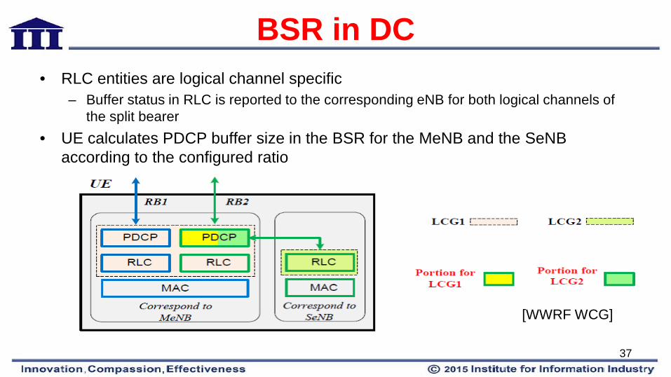
BSR in DC • RLC entities are logical channel specific
– Buffer status in RLC is reported to the corresponding eNB for both logical channels of the split bearer
• UE calculates PDCP buffer size in the BSR for the MeNB and the SeNB according to the configured ratio
[WWRF WCG]
37
Legacy LCP procedure • TS 36.321
– UE shall maintain a variable Bj for each logical channel j. Bj shall be initialized to zero when the related logical channel is established, and incremented by the product PBR × TTI duration for each TTI.
• PBR-Prioritized Bit Rate of logical channel j – Bj can never exceed the bucket size.
• Bucket size of a logical channel is equal to PBR × BSD. • PBR and BSD are configured by upper layers
38
LCP procedure in DC • Common/separate token bucket modeling. • PBR of the original split bearer needs to be divided by a
configured ratio between the corresponding logical channels.
• Common token bucket – Two logical channels of the split bearer share the same token
bucket – Bucket size reuses that for the original bearer.
39
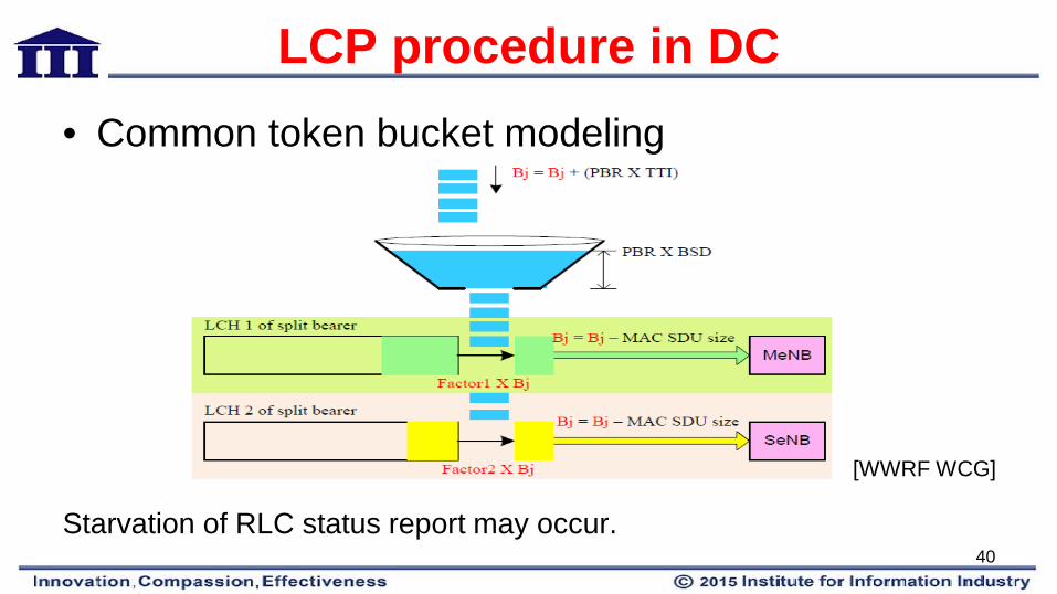
LCP procedure in DC • Common token bucket modeling
Starvation of RLC status report may occur.
[WWRF WCG]
40
LCP procedure in DC • Separate token bucket
– Each logical channel maintains its own token bucket independently.
– Increasing rate of tokens for each bucket is according to its split rate of PBR.
• In release 12 LTE DC, separate token bucket modeling is
adopted.
41
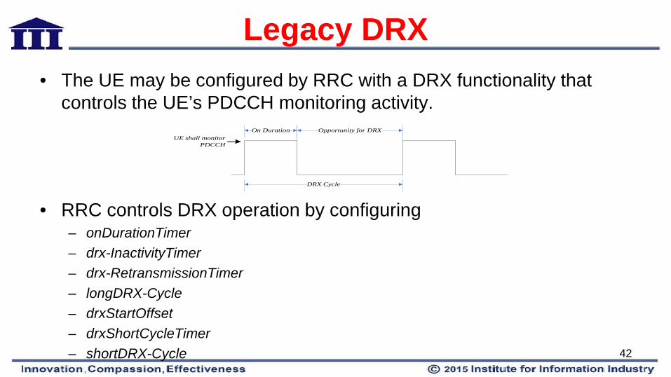
Legacy DRX • The UE may be configured by RRC with a DRX functionality that
controls the UE’s PDCCH monitoring activity.
• RRC controls DRX operation by configuring – onDurationTimer – drx-InactivityTimer – drx-RetransmissionTimer – longDRX-Cycle – drxStartOffset – drxShortCycleTimer – shortDRX-Cycle
UE shall monitor PDCCH
On Duration
DRX Cycle
Opportunity for DRX
42
DRX in DC • MeNB and the SeNB cannot obtain each other’s cell
status in time. • Exchange of the DRX parameters configuration between
the MeNB and the SeNB.
• Whether to align DRX operation between two eNBs is up to implementation.
43
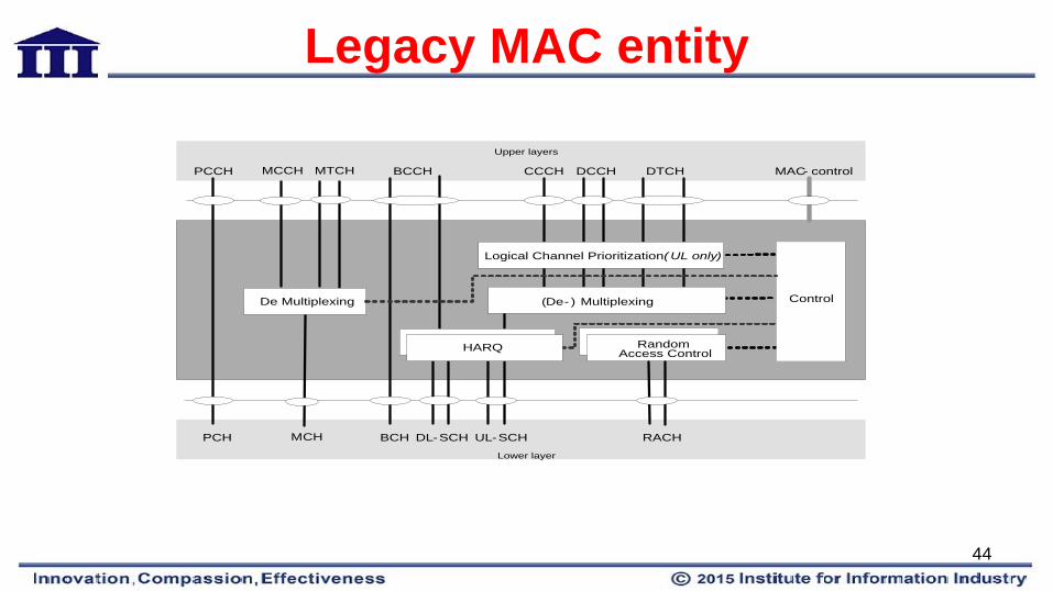
Legacy MAC entity
Random Access Control
PCCH BCCH CCCH DCCH DTCH MAC- control
Upper layers
PCH BCH DL-SCH UL-SCH RACH
Lower layer
(De- ) Multiplexing
Logical Channel Prioritization ( UL only)
Control
MCCH MTCH
MCH
De Multiplexing
HARQHARQ
44
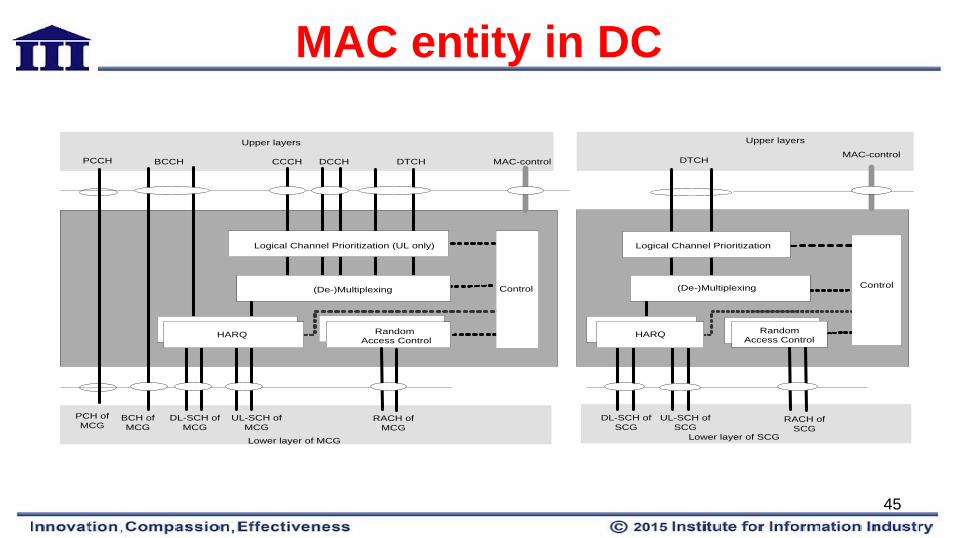
MAC entity in DC
DTCHMAC-control
Upper layers
DL-SCH of SCG
RACH of SCG
Lower layer of SCG
(De-)Multiplexing
Logical Channel Prioritization
Control
HARQHARQRandom Access Control
PCCH BCCH CCCH DCCH DTCH MAC-control
Upper layers
BCH of MCG
RACH of MCG
Lower layer of MCG
(De-)Multiplexing
Logical Channel Prioritization (UL only)
Control
HARQHARQ
UL-SCH of SCG
DL-SCH of MCG
UL-SCH of MCG
PCH of MCG
Random Access Control
45
Outline • Background • Scenario • Architecture • User Plane feature • Control Plane feature
46

Control Plane Feature • For a UE configured with DC, all RRC messages on
SRB1 and SRB2 (both in downlink and uplink) are transferred via the MCG. – eNB Sychronization – System information acquisition – SeNB radio resource management – Selection of connection at the UE
47
eNBs Synchronization • Not required for the MeNB and SeNB to be SFN synchronized
– (not like the carrier aggregation (CA) case in which the aggregated serving cells from the same eNB are strictly SFN synchronized).
• The UE may only need to obtain SFN of one special cell in the
SeNB, i.e. the always activated cell with configured PUCCH.
48

System information acquisition • In Rel-10 and Rel-11 CA technology, system information of all SCells
is configured to the UE by dedicated RRC signaling.
MeNB SeNB UE
RRC Container with SIs of cells in SeNB
RRCConnectionReconfiguration (SIs of cells in SeNB)
RRCConnectionReconfiguration Complete
RRCConnectionReconfiguration Complete
49
SeNB radio resource management
• SeNB is primarily responsible for allocating radio resources of its own cells.
• Inter-eNB coordination is needed for – UE capabilities – Cell/bearer management – QoS requirements
• Information is exchanged through RRC containers carried in X2 messages and both eNBs can understand each other’s radio resource configurations.
50
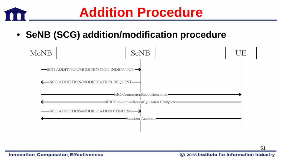
Addition Procedure • SeNB (SCG) addition/modification procedure
51
Selection of connection at the UE
• MeNB decide which SeNB as additional connection for the UE based on UE’s measurement report.
• In future releases, it is a potential candidate or migration path to have the UE to decide which SeNB to connect with – Quality of wireless signal, can be best measured at the UE,
battery usage, running application.
52

References 1. RP-122033 New Study Item Description: Small Cell enhancements for E-UTRA and E-UTRAN
Higher layer aspects NTT DOCOMO, INC. 2. RP-132069 New Work Item Description: Dual Connectivity for LTE NTT DOCOMO, INC., NEC
Corporation. 3. 3GPP TR 36.842 Study on Small Cell Enhancements for E-UTRA and E-UTRAN-Higher layer
aspects. 4. 3GPP TR 36.932 Scenarios and requirements for small cell enhancements for E-UTRA and E-
UTRAN. 5. 3GPP TS 36.331 Evolved Universal Terrestrial Radio Access (E-UTRA) Radio Resource Control
(RRC) protocol specification. 6. 3GPP TS 36.321Medium Access Control (MAC) protocol specification.
53