Embed Size (px)
Citation preview
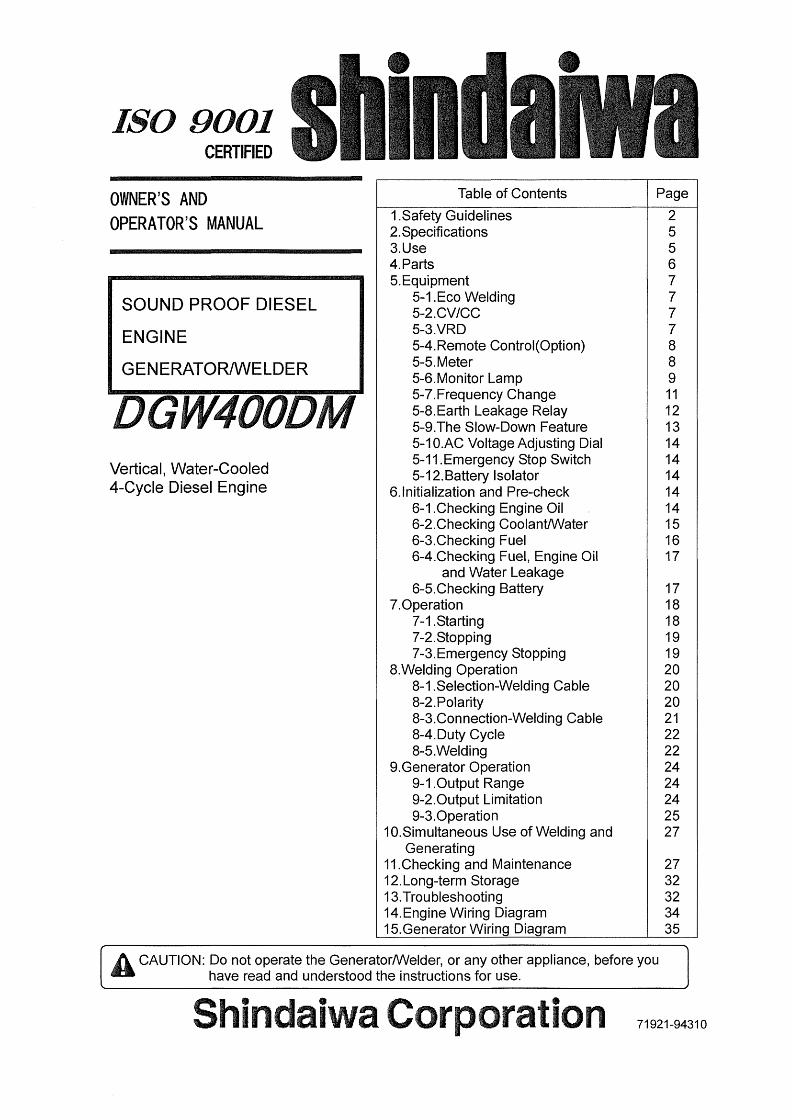
ISO 9001 CERTIFIED
e e
OWNER'S AND
OPERATOR'S MANUAL
SOUND PROOF DIESEL
ENGINE
GENERArl-OR/WELDER
Vertical, Water-Cooled
4-Cycle Diesel Engine
lable of Centents
1.Safety Guidelines
2.Specifications
3.Use4.Part$
5.Equipment 5-1 .Eco Welding
5-2.CV/CC 5-3.VRD 5-4.Remote Control(Option) 5--5.Meter
5-6.Monitor Lamp 5--7.Frequency Change 5-8.Earth Leakage Relay 5-9.The Slow-Down Feature 5--1O.AC VoltageAdjusting Dial
5-11 .Emergency Stop Switch 5-12.Battery lsolator6.Initialization and Pre-check
6-1 .Checking Engine Oil 6-2.Checking CooIantAIVater 6-3.Checking Fuel 6-4.Checking Fuel, Engine Oil
and Water Leakage 6-5.Checking Battery7.0peration
7- 1 . Sta rting
7-2.Stopping 7-3.Emergency Stopping8.Welding Operation 8--1.Selection-Welding Cable
8-2.Polarity 8-3.Connection-Welding Cable 8--4.Duty Cycle
8-5.Welding9.Generator Operation 9-・1 .0utput Range 9--2.0utput Limitation
9-3.0peration10.Simultaneou$ Use of Welding and
Generating11.Checking and Maintenance12.Long-terrn Storage
13.Troubleshooting14.Engine Wiring Diagram15.Generator Wiring Diagram
Page
2
55
67
7
778
8
9
"12131414141414151617
1718181919
20202021
22222424242527
2732323435
A CAUTION: Do not operate the Generator/Welder, or any other appliance, before you
have read and understood the instructions for use.
Shindaiwa Coypeifation71921-9431O

Introduction
Thank you for purchasing Shindaiwa Sound Proof Diesel Engine GeneratorAAIelder.
g This user manual was created to ensure the safe operation of this equipment.
Therefore, the manufacturer of this equipment strongly recommends that the
user follow the in$tructions herein, to avoid unnecessary accidents and repairs.
e PIease operate this equipment after thoroughly reviewing and understanding the
contents of this manual.
g Please attach this manual, if the equipment will be sub-leased.
op Please store this manual nearthe equipment foreasy reference.
ptFollowing conventien will be used throughout the manual te indicate the degree of cautiens.
ODanger CancauseseriousinJuriesor death
Acaution Cancauseminorinjuriesorotherproperties.
damage to the equipment or
<Caution> Othertypesofcaution
op Even some of the items noted in ffACaution g may Iead to serious injuries.
Please read all item and follow all the safety guidelines.
-1-

O Danger : Suffocation from exhaust fume
g Exhaust fume from the engine contains many elements harmful to human. Do
not operate this equipment in poorly ventilated area, such as inside a room or in
a tunnel.
O Danger : Electric Shock
pt Close all doors and place locks during operation.
g Do not touch the output terminals during operation.
& Do not insert metal objects (such as pin or wire) into plug-in receptacles.
e Do not touch wiring or electric parts inside the equipment during operation.
ge Before connecting or disconnecting a load cable from output terminals, always
turn the circuit breaker to OFF position.
g Before connecting or disconnecting a welding cable from output terminals, stop
the engine, and remove the engine key.
$ Before perforrning any equipment check or maintenance, stop the engine, and
remove the engine key. A persen performing the rnaintenance should always
keep the key.
Q Danger:Burns g Do not open the radiator cap while operating this equipment or immediately after
stopping the equipment, to avoid sustaining burns from hot vapor.
O Danger:lnjuries e CIose all doors and place locks during operating this equipment,
by unintentional touching cooling fan and fan belt.
to avoid injuries
A Caution : Suffocation from exhaust fume
pt Do not point the exhaust fume toward pedestrians or building.
A Cautien : Suffocation from welding fume
e Be sure to wear a fume proof rnask in operation, because welding fume contains
poisenous gas and dust. Pay attention to the airflow direction and suracient
veRtilation also in order te prevent from inhaling the furne.
A CautioR : Injuries to eye$ and skin
g Be sure to wear spark protection glass(es), Iong-sleeve shirts, gloves,
order to protect eyes and skin frorn harmful spark in welding.
ec Battery fiuid contains diluted sulfuric acid. Avoid contact with eyes, skin
clothing. If the acid comes in contact, especially with eyes, flush with a
water, and contact your physician immediately.
etc. in
or onIot of
A Caution : EIectric sheck
e Do not flush water onto the equipment nor operate it in the rain.
A caution:Explosion
ge Do not use the equipment or charge the battery, in the case the battery fluid level
is Iower than the LOWER Ievel.
& Battery may emit some combustible gas, so keep it away from fire and sparks.
-2-

-S --
"peAotuej eJesyed eq}y jo peg!pow 6u!eq sgueuad!nbe equ! `}ueLud!nbe eq; eleJede }ou oa tw
'eu!6ue em do}s sAeMle `eoueuelu!ew pue Moeuo ;ueLud!nbe 6u!LuJoyed ueqM e
'uo!}eJedo 6u!Jnp lueLud!nbe eq; eAotu }ou oa e
'uo!l!sod ddo ovexeeaq}!noJ!o eqnes pue luewd!nbe pepeuuoo eql llo uJn} `eu!6ue eq} 6u!yels ueqAA tw
・6u!pus uroJJ}ueLud!Rbe eql deex ol `GoeJ.ins elqe}s pue }eu e uo lueiMd!nbe oql eoeld sKeMlv ts
・6u!p!lsuJoJnuetud!nbe eq; deex ol Al6uoJ}s l! xy `sxonn Aq }uecad!nbe eq; 6u!/UJeo ueqAA Q
'lio 6u!xeejq elpueq o; enp do]p o} luewd!nbe esneo
KeLu ;! jos `qpueq e lj
pt LocationofWamingIabels
When the waming labels become unreadable or damaged, the appropriate locations, as specified in the following figure.
When ordering the label, use the following part numbers.
place new labels on
o@@@@@o@@
Suffocation from exhaust fume (No. 19402--OOI94)
Suffocation from welding fume (No. 19402--OOI95)
EIectric shock (No. 19402-OOI93)
Electric shock (No. 1 9402-O0242)
lnjuries (No. 19402-OOI99)
Bums (No. 19402-O0201)
Bums (No. 19402-O0200)
Fire (No. 19402-OO166)
Bums (No. 19402-O0256)
9 7
6
2
&
"
o
8
<kS'
gu as
<!s>
ss
1
oOo
b
tif 'tt4. -・
oL (fiI)]
ta
o
0rf
twEfoge
ij,I
5"
4 (INSIDE)
3
-4-

Model DGW400DMGeneratingMethod RotatingField
RatedCurrent(A) 370/390
RatedVoltage(V) 34.8135.6
DutyCycle(O/o) 60
RatedSpeed(miR-G) 3000/3600
NoLoadVoltage(V) MAX856'aiias8gs}
Single CurrentAdj.Range(A) 90--380111O-400
WeldingRod(¢) 2.6-8.0
Dual CurrentAdj.Range(A) 50---190/55-21O
co
mA=L
cu¢=gOo
waQ8=vo
WeldingRod((i)) 2.0-4DEco CurrentAdj.Range(A) 40-220
WeldingRod((S)) 2.0-5.0
RatedFrequency(Hz) 50160RatedSpeed(rnin-i) 3000/3600
Phase l-Phase 3-Phase
i・
RatedVoltage(V) 240 415
PowerFactor 1.0 O.8
RatedOutput(kVA) 1O.8 15
Rating Continuous
Model KubotaDlO05
Type Vertical,Water-・Cooled4-CycleDieselEngine
DisplacemeRt(L) 1.001
RatedOutput(kw/min-") 20.413600(Grosslntermittent)
16.513000or19.113600(Netlntermittent)2-th,s
Fuel ASTMNo.2DieselFuelorEquivalent
LubricantOil APICIassCDorHigher
LubricationOilVolume(L) 5.l(Effectivei.4)
CoolingWaterVolume(L) 4.3(SubTankCapacityO.6Lincluded)
StartingMethod StarterMotor
Battery 55B24L
FuelTankCapacity(L) 37
Length(mm) a5192o=
.g.g
aWidth(mm) 700
Height(mm) 760
DryWeight(kg) 455
pt
ggaj
Arc Welding
CV Power Output (Side A only)
EIectric Tbols and HorneAppliances
Power Source for Iights
A Cautien : Damage to the equipment or other propertie$
g The equipment is designed for the above purposes enly. Do not use it for the
other purpose. When it will be used for the equipment with the microcomputers
control or for the ultra-precision devices, the load may be malfunctioned.
g Whenever connecting to use medical equipmeRt or appliances, be sure to
consult with the medical equipment company, doctor or hospital personnel.
-5-

AC METER\
bV/CC \SELECTOR SW I TCH \
EMERGENCY DC METER ECO/S I NGLE/DUAL CURRENT ADJ、 DIAL A
rTOP SW I TCH SELECTOR SWITCH
@ 順
/\ \ \ / /
蟹 騨 脚
CURRENT ADJ. DIAL B
@ MONITOR LAMP
@ STARTER SWITCH
@ FUEL METER
鼻躍卯 踊箇
● 璽 璽 爾uo
レ/F『 鼠 揃 隈 R 鼠畝
W lwσ / \ \\
RTH LEAKAGE CIRCUITdAKER(ELCB)
uOLTAGE ADJ. DIAL
@ HOUR METER
vELDING TERMINAL A
aONNET GROUNDING@ TERM I NAL
/
\
REMOTE CONTROL@ RECEPTACLE
rLOW DOWN SWITCH
@ VRD SWITCH
vEL ING正RMINAL、 ノ
1-P RECEPTACLE
HOLES FORTHE FORKLIFT
、 ,
LE “ o
1、、・
一
3-P@ _』一一3-P一…㎜瀬一一・鰍 酬ε 腰
@ 圏曲
、D . .==卜1-P 霞藝翼騒i璽}
RECEPTACLE
BREAKER
BREAKER
FUSEUPPEIミ 50A
LOWER 20A
団SIDE DOOR
BUS BAR
COVER
FREQUENCY LEVER
BATTERY
FUEL LEVERSTRAINER
o o
賢澤O O
o
圏垂醤 。。。。
AIR CLEANER
RAD I ATOR
OIL PLUG
OIL INLET
OIL GAUGE
SUB TANK
OIL FILTER
BATTERYISOLATOR
FUEL DRAIN PLUGOIL DRAIN PLUG WATER DRA I N PLUG
\
MUFFLEREL INLET LIF
hNG LUG/HANDL
6 \
噛 癒^レ欄
/
/NDLE TOP PLATE EXHAUST
PORT
一6一
5-1. Eco Welding
The equipment is incorporated in Eco welding features that are aimed at performing
the Iower noise, the Iower fuel consumption and the lower gas emission than
conventional models.
When you turn the selector switch to Eco, you will be able te weld with Max. 5.0mrn
¢welding rod at the slow down speed.
<Caution>
g When welding is performed, de not turn the output selector switch, which causes
the burnout of the switch.
g Eco is designed forwelding only. When AC output power is used by mistake, you
cannot u$e either welding or generating due to output decreasing.
5-2. CV/CC
The equiprrient incorporates CV (Constant Voltage) characteristic feature at sideA.
Connecting a wire feeder and then tuming to the CC/CV Selector Switch to [CV],
semi-・automatic welding such as MIG MAG SS, etc. is available to perforrn.
When the CC/CV selector switch is positioned at [CVI, the current frorn Side A
terminals becomes Constant Voltage Characteristic. Therefore, you have to adjust
voltage by the voltage adjust dial.
When the CC/CV selector switch is positioned at [CC], the current frem Side A
terrninals is Constant Current Characteristic. Therefore, you have to adjust current by
the current adjust diai A.
<Caution>
S When welding is performed, do not turn the output selector switch. It may cause the
damage of switch.
S "CC"shows"Quasi"ConstantCurrentCharacteristic.
pt Side B Output ferrninals are to output CC (Constant Current) only. Even ifthe
selector switch is turned to [CV (Constant Voltage)], they cannot output [CV] power.
5-3. VRD
The equiprnent incorporates VRD (Voltage Reduction Device) feature, for the
purpo$e of protecting an operator from electric shock with welding current. When the
VRD switch is turned to ON, the voltage changes to 35V or lower during no welding
period.
-7-

5-4. Remote Control (Option)
Remote control operation to SideA is available, by connecting the remote control box.
Ybu can adjust the welding current (in CC condition) and welding voltage (in CV
condition) to the current from Side A terminals.
es RemoteControlBoxConnection O lnsert the plug of the remote control box into the remote control receptacle.
REMOTE CONTROL RECEPTACLE
:-: ltljx
saswh l
@@5 @e;ee
".
BEE]]
l )
'-i
e@@e.:
(ii} e
REMOTE CONTROL BOX
<Caution>
ew Never connect the plug of the remote control box to the receptacle of the extension
cable reel when the reel is connected to AC output receptacle.
e Never connect the other loads additionally than the remote control box.
e ln the case the extension cable reel is installing the breaker, use the equipment to
have turned the breaker ON.
5-5. Meter
The equipment incorporates digital meter$, voltage & amperage of welding current
and also 3-Phase Voltage & frequency ofAC output.
(1) DC Vblt Meter - Ampere Meter
Each meter displays welding voltage and amperage in $ideA or Side B terminals.
When the output selector switch is positioned at EEcol or [Single], the rneters do not
display the voltage or the amperage in Side B terminals.
(2) 3-Phase Volt Meter
The meter displays the 3-Phase voltage (U-V) in AC output.
(3) Frequency Meter
The meter displays the frequency in AC output.
<Caution>
g The 3-Phase Volt meter reads 380-4t5V, apart from the circuit breakers (3-P and
1-P) positions to ffONS or ifOFFg , when the engine is driving.
-8-

5-6. Monitor Lamp
The equipment is incorporated in monitoring function of WATER TEMP, BATTERY
CHARGING, OIL PRESSURE, Hz/OVERHEAT.
WATER TEMP OIL PRESSURE
//U
1
N
memoNpm
BATTERY CHARGE OVERHEAT
Under normal condition, when the starter switch changes from STOP to RUN, all the
larnps of BArrERY CHARGING, OIL PRESSURE and Hz/OVERHEAT turn ON.When the engine starts, all the lamps turn OFF. When abnormality is detected on
other than Hz/OVERHEAT, the corresponding rnonitor lamp will flash, and the engine
automatically shutoff.
When the automatic shutoff is engaged, turn the starter switch to STOP position once,
and then restart the engine. In the event the automatic shutoff is engaged next time,
check which larnp turns ON or OFF and point out where is the abnormality.
(1) CeolantlWater femperature Menitor Lamp
O Danger: Injuries
e Close all doors and place locks during operating this equipment, to avoid
injuries by unintentionally touching cooling fan and fan belt
O Danger: Burns
e Do not open the radiator cap while operating this equipment or immediately
after stopping the equipment, to avoid sustaining bums frem hot vapor.
A Caution: Bums g Do not touch the eRgine and muffler during operation and immediately after
stopping the equipment, for the temperature can reach extremely high.
When the water temperature rises abnormally, the coolanblwater temperature moniter
larnp will fia$h, and the automatic shutoff will be engaged.
When this occurs, check the coolantiwater re$ervoir tank, and replenish if needed.
(Refer to No. 6-2 Checking coolantiwater ternperature.)
lf the water level is normal, there may be a possibility of overloading. AIway$ use the
equipment within the rated duty cycle and output power.
(2) Battery Charge Monitor Lamp
When the battery turns unable to be charged during operation, the battery charge
monitor lamp will flash and the automatic shutoff will be engaged.
In the event this occurs, consult with the authorized distributor or our engineering
section.
<Caution>
g The battery charge monitor cannot detect the degradation of the battery nor the
battery fiuid level. Check the battery fluid level periodically.
(Referto ff6-5. Checking BatteryS )
-9-

(3) Oil Pressure Monitor Lamp
O Danger:Injuries
g Close all doors and place locks during operating this equipment,
injurie$ by unintentionally touching cooling fan and fan belt.
to avoid
A caution:Burns
e Do not touch the engine and muffler during operation and immediately after
stopping the equipment, for the temperature can reach extremely high.
ee When checking engine oil, always stop the engine, and waituntil the engine
cools down. If you open either the oil gauge or the oil filter cap during operation
hot oil may cause some injury.
When the engine oil pressure drops during operation, the oil pressure monitor lamp
will fiash, and the automatic shutoff wi
When this occurs, check the engine oi
needed.
be engaged.
Ievel, and replenish to the rr}aximum Ievel if
<Caution>
@ The engine oil pressure menitor cannot detect the degradation of engine oil itself.
Please check the engine oil periodically, and change if needed.
(Referto ff11.MaintenanceA )
e Check the fuse next, when the abnormality, other than WltsCTER TEMP, BAITERY
CHARGED OR OIL PRESSURE is detected. If the fuse is burned out, consult with
our authorized distributor or our engineering section, because there may be an
abnormality of electric/electronic parts or wiring and repairing may be required.
(4) HzlOverheat Monitor Lamp
si UnlessthefrequencyselectorIeverposition
and the bus bars in the equipment are
correspondent to each other, Hz/OVERHEAT
rnenitor lamp wHI tum ON.
$ Hz/OVERHEATmonitorlampmayfiash in the case the machine is used excessively
ever the duty cycle.
ON ABNORMAL FREQUENCY
FLASH OVERHEAT
<Caution>
g When HzlOVERHEArr rnonitorturns ON, as the output power reduces remarkably,
the AC output power can hardly be used.
g There may be a case that the Iarnp will not fiash, depending en the welding type or
the weather condition.
-10-
5-7. Frequency Change
O Danger:Injuries
" Frequency change should be done, aher stopping the engine. Moreover, close
doors and place locks during operating this equipment, to avoid injuries by
unintentionally touching cooling fan and fan belt.
O Danger: Electric Shock
@ Never touch the frequency change bus barduring operation.
A Caution: Burns
pt Do not touch the engine and muffIer during operation and immediately after
stopping the equipment, for the temperature can reach extremely high.
The equipment can be used to 50Hz and 60Hz. Select the frequency according to
the load.
(l) Stoptheengine.
@ Open the side door.
SIDE DOOR
SCREW
COVER
ool.muI / l&
Wc:
croethtooo/
c:
/ eelsuV
rw"c
stEb
b'
l l
-(.
id
lr)i
・l
@ Remove the cove r. (M6 Screw 3 pieces) BUS BAR
ooN /rwI/ 1gJva
ee.
t]1
/afsljl
QUENCY
ZLEVER
@ Turn the selector switch and the metal bus bars to the other frequency as per the
drawing.
BUS BAR BUS BAR
60Hz-50Hz
FREQUENCY LEVER
5OHz--.6OHz
FREQUENCY LEVER
@ Reinstalithecover.@ Sta rt the engine. (Refer to if7-1. Sta rtingS )
(2) Tu rn the slow-down switch to OFF. (Refer to if5-9. SIow--DownS )
@ Check the frequency in the frequency meter in the control panel.
-11-

5-8. Earth Leakage Relay
O Danger : Electric Shock
g Ground every grounding terrninal to the earth as set eut in the manual.
If even one of all is unconnected by mistake or accident, it will be much more
dangerous for human body than the NO RELAY case, because leaking current
inevitably goes through the body.
pt Even though all the terminals of the loads have been grounded to the earth, the
bonnet (canopy) grounding terminal should be grounded to the earth.
ee Grounding should be made afterthe engine is stopped.
$ Wheneverthe earth leakage relay has activated, you should always repairthe
leaking place first of all.
The equipment is provided with the earth leakage relay in the Circuit Breaker to
detect any leakage arisen due to the treubles as insulation failure of the load while
the generator is running. And cutting off the circuit for protection against any accident
such as electrical shock resulting from the trouble.
The specifications of the earth Ieakage relay:
g Rated Sensitive Current: 30mA (or below)
(Grounding resistance: 5009 or below)
(1) Grounding Work The qualified electrician should perform the grounding work of the following 2
points(500{;i} orbelow).
e The Outer Bonnet of the equipment (bonnet grounding terminal)
e The Outer Bonnet of the Ioad
BONNET GROUNDINGTERMINAL
GROUNDING ROD
({i{gl}i,
ggit ts.
ss
sso9
a
<Caution>
g ln the event you cannot ground the generator to the earth, consult with the
authorized distributor er our engineeriRg section.
(2) Operation Check
Before operating the equipment, check always if the device can work duly as shown
in the following procedure.
(ID Start engine after turning the slow-dowR switch to OFF.
@ Turn (Push-up) the ELCB (lever) to ON position.
@ Push the test button. The device is found to be normal when the ELCB (lever)
turns to OFE
-12-

ve TESt
I
oidr
¥/
rJi@
di
cc
BUTTON
ELCB
@ ln the event you cannot complete all steps in the above procedure to the end, the
device is out of orden Consult with our authorized distributor or our engineering
section to repair.
(3) The Earth Leakage Relay has activated
A Caution : ElectricShockllnjuries
pt Be sure te disconnect all the loads to the equipment when turning the breakers
ON again, after the earth leakage relay has activated.
When the earth leakage relay has activated, the ELCB (lever) turns to Ol:E
ln the case, stop the engine promptly and find the leakage point to repair.
After repairing leakage point(s), return (push up) the ELCB (lever) to ON.
5-9. The SIow-Down Feature
The slow-down feature is to set the engine $peed low automatically (in about 8
seconds) for the purpose of reducing noise aBd fuel consumption, whenever no
welding operation or electric supply is performed.
In the case of using the SLOW-DOWN feature, turn the slow-down switch to ON.
By the condition, the engine automatically moves to high speed, whenever welding
operation or electric supply starts.
A Caution : Damage to the equipment or other preperties
g Turn alway$ the slow-down switch to OFF, when the load is incorporated with
any magnet switch.
<Caution>
$ When the load of less than O.5A is connected to use, the Slow-Down feature does
not function sometirnes. Therefore, turn the switch to OFF.
g When welding operation or electric supply performs alternately or intermittently, turn
the switch to OFF.
$ When the output selector switch is positioned to Eco, the engine does not turn to
high speed.
-l3-

5-1O. AC Voltage Adjusting Dial
Adjust the dial whenever theAC Output adjustment is necessary.
VOLTAGE ADJ. DIALx{gypt
-xxOdyeeiw{
--(illlll
LECREASE 'TINCREAxu・
<Caution>
g When raising the voltage, the current is decreasing. (Use the output within the
output capacity.)
g ln you raise the voltage exceeding the allowable voltage range, which causes the
damage to the Ioads.
5-11. Emergency Stop Switch
This switch is used to stop the engine in emergency.
By pu$hing the switch, the engine stop$.
Be sure to restore the starter switch to STOP and re-set
the switch, tuming clockwise after using the emergency stop
switch.
5-12. Batteiy lsolator
When turning the Battery lsolator Lever to
OFF position, the engine electric circuit does
not get battery power.
STOP
tw×
o
ow
@o
RESET
D
OFF po$ition
o @elro
D
ON position
6. Initialization and Pre-check
A Caution:FirenBurnsnlnjuries
e When checking engine, always stop the engine, and keep away from fire. Wait
until the engine cools down, before performing any checks.
6-1. Checking Engine Oil
When checking for engine oil, be $ure to keep the equipment leveled, and insenthe
oil gauge all the way in.
Prior to starting the equipment, make sure to fiIl the engine oil to the UPPER Iine
through the oil inlet.
SIDE DOOR :gh
OIL PLUG OIL INLET
oIL GAUGE iL-!iiiiiiEi oIL DRAIN PLUG
-14-

<Caution>
op lfthe equipment is not Ieveled, you cannot obtain accurate oil level.
Do not overfill (over UPPER line) the engine oil. The excessive amount ef engine oil
may damage the engine (inside the cylinders)
M Selectingproperengineoil
<Caution>
ee Use the API class CD or higher.
(5. IL)
UPPER LEVEL=-:,-/.---E-l.tLli,i--IIEFFEcTlvE
----:-rr--= LOWER LEVEL
(3.7L)
Visco$ity and femperature
Temperature Over+200c +1O.v+200c -1O.v+4OOc
Viscosity SAE30 SAE20 SAHOW/3O
6-2. Checking Coolant 1 Water
O Danger:lnjuries
e Close all doors and place locks during operating this equipment, to avoid
injuries by unintentionally touching cooling fan and fan belt.
O Danger:Burns e Do not open the radiator cap while operating this equipment er immediately
after stopping the equipment, to avoid sustaining burns from hot vapor.
A Cautien:Burns & Do not touch the engine and muffler during operation and immediately after
stopping the equipment, for the temperature can reach extremely high.
Check to see if the coolant/water level is between FULL and LOW levels in the sub
tank. If the coolantlwater is below the LOW Ievel, fill the tank and the radiater
accordiBgly.
(1) Filling te the Reservoir Tank
(D Remove the sub tank cap. ,/SIDE DOOR@ Fill up the sub tank to the FULL level.
@ lnstall the cap back.:
f' ca
CAP
SUB TANKi oeeoeeo
-15-
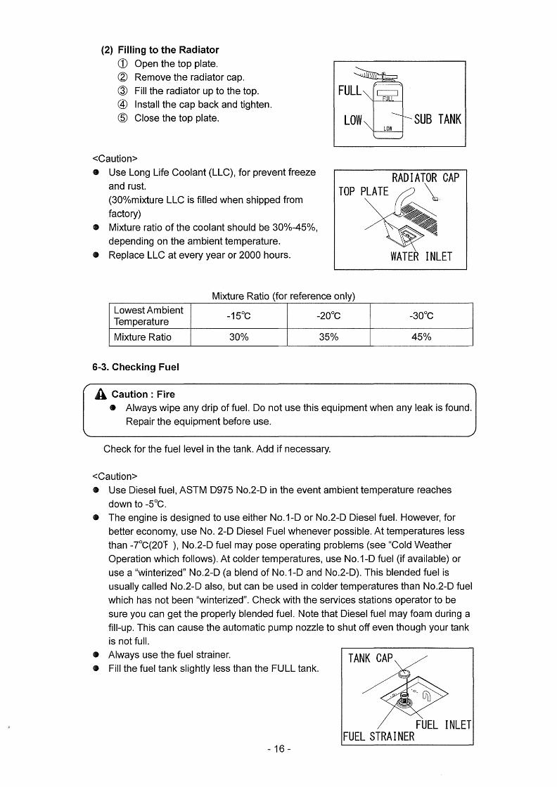
(2) Filling to the Radiator
(D Open the top plate.
@ Remove the radiator cap.
@ Fill the radiator up to the top.
@ lnstall the cap back and tighten.
@ Close the top plate.
FULL Are>[==I]FgLLLLx
ow× N'xLOW
L)SUB TANK
<Caution>
g Use Long Life Coolant (LLC), forprevent freeze
and rust.
(30%mixture LLC is filled when $hipped from
factory)
pt Mixture ratio ofthe coolant should be 30%-45%,
depending on the ambient temperature.
g Replace LLC at every year er 2000 hou rs.
RADIATOR CAPTOP PLATE Xx
,,ggessssG
WATER INLET
Mixture Ratio (for reference oniy)
LowestAmbientTemperature
-150c -2OOc -3OOc
MixtureRatio 3oo/, 350/o 450/o
6-3. Checking Fuel
A Caution:Fire e Always wipe any drip of fuel. Do not use this equipment when any leak is found.
Repair the equipment before use.
Check for the fuel level in the tank. Add if necessary.
<Caution>
g Use Diesel fuel, ASTM D975 No.2-D in the event ambient temperature reaches
down to -sOc.
e The engine is designed to use either No.1-D or No.2-D Diesel fuel. However, for
better economy, use No. 2-D Diesel Fuel whenever possible. At temperatures less
than -70C(20T ), No.2-D fuel may pose operating problems (see "Cold Weather
Operation which follows). At colder temperatures, use No.1-D fuel (if available) or
use a "winterized" No.2-D (a blend of No.1-D and No.2--D). This blended fuel is
usually called No.2-D also, but can be used in colder temPeratures than No.2-D fuel
which has not been "winterized". Check with the services stations operator to be
sure you can get the properly blended fuel. Note that Diesel fuel may foarn during a
fill-up. This can cause the automatic pump nozzle to shut off even though your tank
is not full.
$
e Always use the fuel strainer.
$ Fill the fuel tank slightly less than the l ULL tank.
-16-
TANK CAP
'e. CFb
FUEL STRAINERFUEL INLET
6-4. Checking Fuel, Engine Oil and Water Leakage
A Cautien : Fire
g Do not use this equipment when a leak is found. Repair the equipment before
use.
Be sure to check any leakage for fuel, oil and coolantiwater at the hose connections
by opening side doors. Whenever checking any fuel leakage, turn the fuel lever
OPEN and be sure to close the fuel lever after checking.
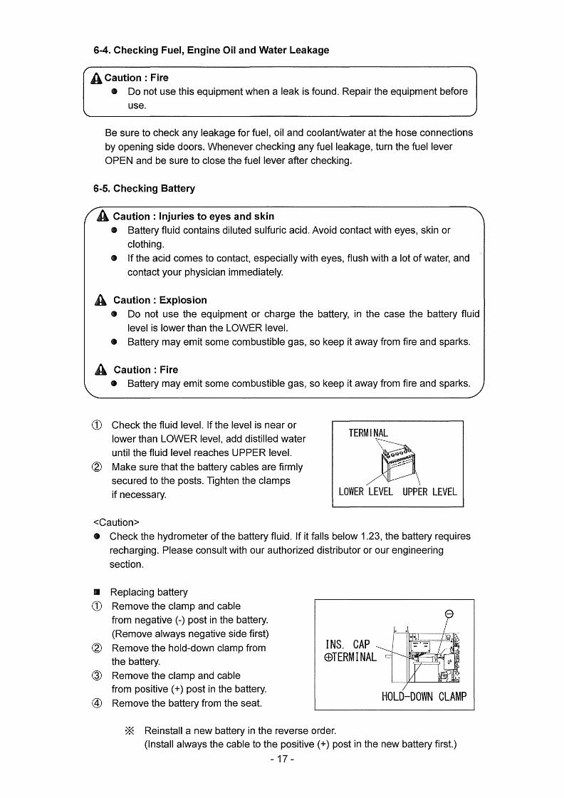
6-5. Checking Battery
A Caution : Injuries to eyes and skin
ig Battery fluid contain$ diluted sulfuric acid. Avoid contact with eyes, skin or
clothing.
$ lfthe acid comes to contact, especially with eyes, fiush with a lot of water, and
contact your physician immediately.
A Caution:Explosion g Do not use the equipment or charge the battery, in the case the battery fluid
level is lower than the LOWER level.
g Battery may emit sorne combustible gas, so keep it away from fire and sparks.
A caution:Fire g Battery may emit some combustible gas, $o keep it away from fire and spark$.
(iD Check the fluid level. Ifthe Ievel is nearor
lower than LOWER level, add distilled water
until the fluid Ievel reaches UPPER level.
@ Make sure that the battery cables are firmly
secured to the posts. Tighten the clamps
if necessary.
TERMINAL
Gag
7$7
LOWER LEiVEL UPPER LEVEL
<Caution>
g Check the hydrometer of the battery fluid. If it falls below 1.23, the battery requires
recharging. Please consult with our authorized distributor or our engineering
$ection.
es
o
@
@
@
Replacing battery
Remove the clamp and cable
from negative (-) post in the battery.
(Remove always negative side first)
Rernove the hold-down clamp from
the battery.
Remove the clamp and cable
from positive (+) post in the battery.
Remove the battery from the seat.
E*{
INS. CAPGSTERMINAL
o o
ew
:#::lr :.
Lgb
a
va/
HOLD-DOWN CLAMP
Reinstall a new battery in the reverse order.
(lnstall always the cable to the positive (+) post in the new batteiy first.)
-17-

<Caution>
g Use the following battery.
55B24L
O Danger : Suffocation from exhaust fume
g Exhaust fume from the engine contains iT}any elements harmful to human.
Do not operate this equipment in poorly ventilated area, such as inside a room
or in a tunnel.
A Caution : Suffocatien from exhaust fume
e Do not point the exhaust fume toward pedestrians or building.
A Caution:Fire op lemperature around muMer and exhaust can get extremely high.
Keep any inflarnmable items (such as fuel, gas, paint, etc.) away frorn the
equipment.
e Always operate this equipment on fiat surface and, at leasM meter away from
any objects (wall, box, etc.)
A caution:Injuries
e Always place the equipment on a flat and stable surface, to keep the
equipment from sliding. Be sure to lock the wheels for the wheeled models.
e Before starting the engine, be sure to disconnect the loads and set the
breaker$ (1-P and 3P) to OFF position.
7-1. Starting
(l) Turn the breakers (1-P and 3-P) to OFF position.
@ Turn the fuel lever to OPEN.
@ Turn the Battery lsolator Lever to ON position.
@ Tum the Slow-・Down switch to ON.
@ Turn the emergency stop $witch to release.
@ When the temperature is below -50C, turn and keep the starter switch to
PREHEA-r until the preheat lamp turns OFF (about 5 seconds).
(Z) Tum the starter switch to START and then the engine starts by the starter
motor.
<Caution>
g Do not drive the sta rter motor for more than
15 seconds successively.
e lf you need to restart, wait for 30 seconds or
more before retry.
(g) Release the switch, as soon as the engine
has started.
<Caution>
ee Once the engine has started, neverturn the
$tarter switch to START
-18-
EMERGENCY STOP SWITCH
r-'hs SWITCH
STARTERSWITCHELCBSLOWDOWN
n-"si
'
wwge uama
tS@,i,,Is.i,Ri
es
el
nsv.---rlnTny.--r"L

@ Keep the engine idle for about 5 minutes.
3-P BREAKER
BREAKER
]
e" e .e'N
r[S]:
e-
ifiiiliiiii
----
l-t-
'
:
"t-a--.)e:i 7X I..
-OPEN
Am
ooi ii.. G S
-ep-
,g 'Q
-tsyij
ckogE
'FUEL LEVER
o @()lio
o
BATTERY ISOLATOR
ON position
N Restart after stopping due to fuel shortage
This equipment is incorporated in automatic vacuuming air feature. Therefore, even
though the engine stops due to running out of fuel, you can restart the engine easily
by the following steps.
(D TurnthestarterswitchteSTOP.@ Fill the fu el.
@ Tum the Slow--Down switch to ON.
@ Turn the starter switch to START and dive the starter motor for abeut 10
seconds.@ Relea$e the starter switch, as promptly as the engine $tarted.
@ Wait for about 1 rninute to vacuum the air out. The engine speed becomes
stable when the air is extracted.
<Caution>
e Never turn the engine NORMAL speed or connect the Ioads until the air is
extracted completely (the engine speed becornes stable)
7-2. Stopping
O Turn (Push-down) the breakers (i-P and 3-P) to OFE
@ Tu rn the SIow-Down switch to ON.
@ Keep the engine idle (cooling down) for about 5 minutes.
@ TurnthestarterswitchtoSTOP. @ Afterthe engine has stopped, turn the fuel leverto CLOSE.
<Caution>
g When the engine does not stop in $pite of tuming the starter switch to STOP,
turn the fuel Iever to CLOSE, then the engine will stop in a few minutes.
In this case, be sure to consult with our authorized distributor or our
engineering section and ask te repair.
@ Turn the Battery Isolator Lever to OFF position.
7-3. Emergency Stopping
The emergency stop feature is incorporated in the equipment.
Push the emergency stop switch in case of an emergency or equipment
abnormality during operation.
-19-

O Push the emergency stop switch to stop engine in an emergency case.
<Caution> e Be sure to return the engine starter switch to [STOPI after the engine stops.
g Never hit the ernergency stop switch by any tool such as a hammer.
e Never use the emergency stop switch except an emergency case.
g Turn the fuel lever to CLOSE to stop in the case the emergency stop switch
does not function.
@ Turn the emergency stop switch to arrow mark (clockwise) to release the feature.
<Caution> g Be sure to re--start the engine after releasing the ernergency stop feature.
The engine does not start again though the starter motor is running, without
releasing the emergency stop feature.
EMERGENCY STOP SWITCH
@@・
STARTER SWITCH
A
l ?iX lnt 'g'. t・opEN-l'ltlllSlyf/
]/gg[].Z・ cyolisE
A, FUEL LEVER
8-1. Selection - Welding Cable
Select the cable with preper gauge, based en the allowable amperage aRd the length,
per the table shown below.
The welding capacity is to reduce if the small gauge cable is used.
<Caution>
e Welding cables $hould be used unstrained. When the welding cables are used
in swirl, the welding capacity is to reduce.
Size of Cable (Unit: mm2)
ReturnLength
WeldingCurrent20m 30m 40m 60m 80m 1OOm
400A 38 50 60 1OO 125 200
35OA 30 50 60 80 125 150
3OOA 30 38 50 80 1OO i25
25OA 22 30 38 60 80 lOO
2OOA 22 30 30 50 60 80
150A 22 22 22 38 50 60
1OOA 22 22 22 30 30 38
8-2. Pelarity
Therearetwoweldingoutputterminals, if+g and ff-S .
Select the polarity according to the operation, referring to the table below
ny# 20 -

<Caution>
g Follow the instruction of the welding rods, the polarity of which is specified.
(1) Welding Rods
Application Connection
NormalPolarityGeneralsWelding,suchasconstruction
PlustotheEarth(Material)Minustoholder(Rod)
ReversePolarity
ThinPIate,Build--Up
Welding,StainlessSteelPIustoholder(Rod)MinustotheEarth(Material)
(2) Semi-automatic wire feeder
Application Connection
NormalPolaritySelfshieldWeld(SmallDiameter)
PlustotheEarth(Material)MinustoTorch(Wire)
ReversePolarityMIGWeldingMAGWeldingSelf-Shield(BigDiameter)
Plu$toTorch(Wire)MinustotheEarth(Material)
8-3. Connection - Welding Cable
O Danger : EIectric Shock
e Before connecting or disconnecting a welding cable from welding output
terminals, stop the engine, and remove the engine key. A person performing
should always keep the key.
o@
Stop the engine.
Connect a welding cable to a crimping
Feeder) , and a material holder.
(1) Welding Rod
WELDlNG
MATERlAL
ROD HOLDER WELDING CABLE
#CRlMPING TERMlNAL
HOLDER
terminal, a welding rod holder (Wire
(2) Semi-automatic Wire Feeder
WIRE FEEDER
WELDING CABLE
Ag='GiXx.cRIMplNG
TERMlNAL
MATERIAL HOLDER
(f) Welding Rod
Eco(Single) Single Dual
WeldingRod2.0-q55.0
WeldingRod2.6-¢8.0
WeldingRodto2.0-¢4.0
WeldingOutputTerminalA WeldingOutputTerminalAWeldingOutputTerrninalA
AndWeldingOutputTerminalB
-21-

(2) Semi-Automatic Wire Feeder
Eco(Single) Single Dual
WeldingWire
MIG/MAG:¢O.6-¢1.0Self-Shield:¢O.9-¢1.6
WeldingWire
MIG/MAG:¢O.6-¢1.2Self-Shield:¢O.9-to2.0
WeldingWire
MIGIMAG:¢O.6-¢1.0Self-Shield:¢O.9-¢1.6
WeldingOutputTerrninalA
@ After connecting cables, be sure to close output terminal covers.
<Caution>
g Be sure to crimp a crimping terminal to a cable and connect the cable to welding
output terminal. Otherwise, welding output terminals may burn out by the heat
caused by insuthcient connections.
$ Do not use a cable without a crimping terminal. If you use the cable, the insulation is
peeled off partIy, to bind to an output terminal, the output terminal may burn out by
the heat caused by insufficient connections and also a bare part of the cable may
touch the bonnet to short-circuit.
g Side B Output ferrninals are to output CC (Constant Current) only. Even if the
selector switch is turned to [CV (Constant Voltage)l, they cannot output [CV] power.
8-4. Duty Cycle
Duty cycle means the weld able time ratio for 1O minutes. This equiprnent is the rated
duty cycle is 60%, namely, the weld able tirne is 6 minutes or less. Be sure to take
4 minutes recess after 6 minutes welding.
<Caution>
g The equipment may be damaged due to overheat, if welding more than 6 minutes
successively or $hort time recess after the welding.
8-5. Welding
A cautien : suffocation frem welding fume
@ Be sure to wear a furne proof mask in operation, because welding fume
contains poisonous gas and dust. Pay attention to the aithow direction and
sufficient ventilation also in order to prevent frem inhaling the fume.
A Caution : lnjuries to eyes and skin
pt Be sure to wear spark protection glass(es)(Refer to the table below),
long-sleeve shirts, gloves, etc. in order to protect eyes and skin from harmful
spark in welding.
Standard for Spark Protection Glass (Japan lndustrial Standard)
No. 7 8 9 10 11 12 13
WeldingCurrent(A) 30-75 76-200 201-400
A caution:Fire g Keep any infiammable items and easily buming items away from the place in
welding, because welding splashes spatters.
A Caution:Burns pt Be sure to wear leather gloves, apron, shoe covers, eye protection
glass(es)(mask), safety shoes, safety cap and long sleeve $hirts, because
welding splashes spatters.
-22-

<Caution>
g Neverturn the output selecter switch during welding, because it causes burnout of
the switch.
2 persons can weld simultaneously.
Each person can adjust the welding current individually.
The current adjustable range by the current adjust dial, depend$ on the position
each of the welding output selector switch.
CURRENT ADJ. DIAL A CURRENT ADJ. DIAL B
CV/CC ECO/S!NGLE/DUALSELECTOR SWITCH SELECTOR SWI'l'CH
.
eor== =]
@@@@ @.
OUTPUT TERMINAL A OUTPUT TERMINAL B
(1) Welding Red
(iD Tum the CV/CC selector switch to ICC-CRISPI or [CC-SOFTI.
Turn to [CC-CRISPI on cellulose rod welding or to [CC--SOFT] on gouging.
@ Tum the output selector switch to [Ecol, ISinglel or [Dual], according to the
operation.
@ Adjust the current amperage by the current adjust dial, per the table below.
PositionWeldingCurrentatthedialposition
FreqMIN 1 2 3 4 5 MAX
Eco 40 60 1OO 140 180 210 220
1Person Single
Use
50Hz 90 120 190 250 320 360 380
60Hz 110 140 200 260 320 380 400
2PersonsDual
Use
50Hz 50 70 1OO 130 160 180 190
60Hz 55 70 110 140 170 200 21O
The values shown ln the table are for reference only. The length and the ambient
temperature affect the value.
When the remote control box is used, the values change to some degree.
(2) Semi-Autorr}atic Wire Feeder
(l) Turn the CV/CC selector switch to [CVI.
@ Turn the output selector switch to IEcol,
operation.
-23-
ISingle] or [Duall, according to the
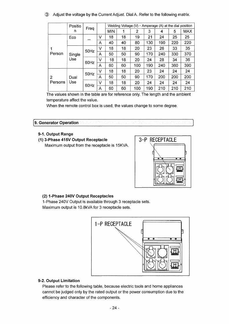
@ Adjust the voltage by the CurrentAdjust. DialA. Refer to the following matrix.
Positio
n
WeldingVoltage(V)tArnperage(A)atthedialpositionFreq
MIN 1 2 3 4 5 MAXEco
-v 18 18 19 21 24 25 25
A 40 40 80 130 ago 220 220
1Person50Hz v 18 18 20 23 26 33 35
Single
UseA 50 50 90 170 240 330 370
60Hz v 18 18 20 24 28 34 36
A 60 60 1OO 190 240 360 390
50Hz V 18 18 20 23 24 24 24
Dual
UseA 50 50 90 170 200 200 2002Persons
60Hz V 18 i8 20 24 24 24 24
A 60 60 1OO 190 210 21O 210
The values shown in the table are for reference only. The length and the ambient
temperature affect the value.
When the remote control box is u$ed, the values change to some degree.
(IE]liEEilfi4iEEEiiiE ==== )9-1. 0utput Range
(1) 3-Phase 41 5V Output Receptacle
Maximurn output from the receptacle is 15KVA.
3-P RECEPTACLE
]
eeeaj=
x..: ll
-pa[
(2) 1-Phase 240V Output Receptacles
1-Phase 240V Output is available through 3 receptacle sets.
Maximum output is 1O.8kV7ts{ for 3 receptacle sets.
1-P EPTACLEEi
i
eQQQ・・crxxx
x×:
--e
-e e-x >hSNe-e
el
-e
gNliliigo
・=-pa] :
9-2. 0utput Limitation
Please refer to the following table, because electric tools and home appliances
cannot be judged only by the rated output or the power consumption due to the
eraciency and character ef the components.
-24-

Applicable Load (For reference purpose only)
Capacity(kW)
Loads1-Phase220-240V
3-Phase380-415V
Receptacle1set
Receptacle
3setuseReceptacle
ElectricBulb,Heater,etc.3.3-3.6 9.9-・lO.8
-
ElectricTools,etc
(SeriesMotor), 1.7-1.8 5.0-5.4 -
MercuryBulb(HighPowerFactorType) 1.3-1A 4.0-4.3 -
SubmersiblePump,Compressor,etc(lnductionMotor)
1.3-1.4 4.0-4.3 6.0
)8( Series Motor : Motor with brush
}*{ lnductionMotor:Brushles$Motor
)K The value described is ifOUTPUTS for lnduction Motor loads and
ffPOWERCONSUMPTIONS fortheotherequipment.
<Caution>
g Be sure to use the frequency designated in the equipment incorporated in mercury
bulb or inductien motor.
ge The Ioad incorporated in motor may require bigger power than the rated power
consumption. Therefore, consult with eur authorized distributor or our engineering
section to clarify.
e When connecting to use 2 or more sets, start the Ioad one by one, not to start them
simultaneously.
$ When switching a Mercury bulb ON again, wait for 15 rninutes (about) until it cools
down.
9-3. 0peration
O Danger : Electric Shock
g Before connecting ordisconnecting a load cable frorn the receptacle$,
always tu rn the ci rcuit breake rs (3-P and 1-P) to ffOFFS position. And
always stop engine, and remove the engine key. A person performing the
maintenance should always keep the key.
g Ground the every grounding terrninal to the earth as set eut in the maBual. If
eveR one of all i$ unconnected by mistake or accident, it will be much more
dangerous for human than the NO-REVXY case, because leaking current
inevitably goes through the body. (Refer to if5-7 Frequency ChangeS . )
g Even though all the current leakage relays in the loads have been grounded
to the earth, the earth grounding terminal and the bonnet (canopy) should be
grounded to the earth.
es Grounding should be made afterthe engine is stopped.
@ Wheneverthe current leakage breakeractivates, you should repairthe
leaking place first of all.
-25-

A caution:Injuries
g Be sure to cennect te output terrninals or insert a plug to a receptacle, after
confirming that all the switches in the loads are positioned to ifOFFg .
g Be sure to select the correct frequency, designated in the loads.
(Refer to if5-7. Frequency Change- . )
A Caution : Damage to the preperty m Aftermath
e Whenever connecting to use medical equipment or appliances, be sure to
consult with the medical equipment company, doctor or hospital personnel.
e Be sure to select the correct frequency, designated in the loads. Otherwise,
the loads may be damaged. (Refer to ff5-7. Frequency ChangeX . )
<Caution>
pt The AC Volt meter reads 3--P output voltage, apart from the circuit breakers (3-P and
1-P) positions to ifONS or ifOFFg , wheR the engine is drMng.
After the engine starts (Refer to if7-1. StartingS ) , operate the equipment as per the
following procedures.
(il) Turn the power switch OFF in the load.
@ Check to confi rm th at the breakers (3--P and 1 -P) position ifOFFg .
@ Connect the load to the output receptacles.
@ Turn the circuits breakers (3-P and a-P) to ifONS. (Ensure the ELCB Iever to be
pesitioned at ON.)
・-PRECEPTACLE3---PRECEPTACLE
E
-
)
'f t`i'-`V.,/
r-t.-
-" e"
-2:-
/3--PBREAKER
/-PBREAKER: t----
.e-
=-.tt'
eq The Circuit Breaker has activated due to overload
A Caution:lnjuries
g Be sure to tum the power switch ifOFF S in the load when turning the circuit
breakerto ffONg again,whenthecircuitbreakerhasactivated.
When the electric supply exceeds the rated output (overload), the circuit breaker
activates to trip off in order to $hut down the circuit. When the Ioad operation stops
during operation, check the circuit breakers (3-P and 1-P).
ln the case the ELCB activates and the ELCB lever positions at OFF, refer to ff5-8.
Earth Leakage Relayg .
When any breaker has tripped, restore the circuit breaker as per the following
procedure.
(D Tu rn OFF all the power switches in the Ieads.
@ Tu rn (push) up the ELCB to ifON£ .
<Caution>op lake care foroverload, referring to if9--2. 0utput Limitationg .
- 26 --

10. Simultaneous Use of Welding and Generating
The circuit breakers (3-P and 1-P) react on the AC power supply circuit only. In the
simultaneous use of welding and generating, there sometimes happens overload to the
engine. Refer to the following table and limit theAC power use.
LimitatioR ofAC Power Supply in the simultaneous use of welding and generating (60Hz)
WeldingOutput ACPowerOutput
WeldingRod/Amperage
OutputSeIect
3-Phase380-415VOutput(P.F.O.8)
1-PhaseOutput
¢2.0rnm/6OA Duai 9.0kVA 1O.5kVA
¢2.6mm/120A Dual 8.5kVA 9.0kVA
¢3.2mm/140A Dual 8.0kVA 8.5kVA
¢4.0mm/170A Dual 7.5kVA 7.5kVA
¢5.0mm/240A Single 2.5kVA 5.0kVA
¢6.0mm/300A Single 2.0kVA 2.5kVA
¢8.0mm/380A Single OkVA OkVAl*E ln order to secure stable AC output, the output selector switch should be positioned
to DUAL in operation as long as possible.
<Caution>
g The simultaneous use of Eco welding and AC power is NOT available.
@ Avoid the simultaneous use in the case high quality result in welding is required.
11. Checking and Maintenance
O Danger : EIectric Shock " lnjuries
e Before performing any equipment check or maintenance, stop the engine, and
remove engine key. A person performing the maintenance should always keep
the key.
A cautien: Fire t Burns
O Keep the equipment far away from fi re.
e When checking engine, always stop the engine, and keep away from fire. Wait
until the engine cools down, before performing any checks.
g Do not open the side panel during operation and irnmediately after stopping
the equipment, because some parts/components (fiexible tube, resistors, etc.)
can reach very high temperature inside the equipment.
<Caution>
e The authorized technicians should perform all checking and maintenance work,
except for the pre-startup checks.
g Request forthe maintenance item with e mark to the authorized distributoror our
engineering section.
pt Always use our genuine pa rts of replacement.
g When draining waste fiuid from the equipment, catch it by tray.
-fo optimize the use of this generator/welder, we recommend the periodical
equipment checks and maintenance based on the following matrix.
Use the hour meter as a guide for the operating time.
-27-
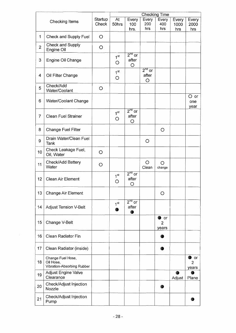
CheckingTime
CheckingltemsStartup
CheckAt
5OhrsEvery1OOhrs.
Every200hrs
Every
400hr$
Every1OOOhrs
Every2000hrs
1 CheckandSupplyFuel o2
CheckandSupplyEngineOil o
3 EngineOilChange1st
o
2naorafter
o
4 OilFilterChange1st
o
2naorafter
o5
ChecklAddWater/Coolant o
6 WaterlCoolantChangeOoroneyear
7 CIeanFuelStrainerast
o
2naorafter
o8 ChangeFuelFilter o
9DrainWater/CleanFuelTank o
10CheckLeakageFuel,Oil,Water o
11Check/AddBatteryWater o
oClean
ochange
12 CleanAirElementtst
o
2naorafter
o13 ChangeAirElement o
14 AdjustTensionV-Be(t1st
ee
2nctor
after
e
15 ChangeV-Belteor
2years16 CleanRadiatorFin e
17 CleanRadiator(inside) e
l8ChangeFuelHose,OilHose,Vibration-AbsorbingRubber
eeor2years19
AdjustEngineValveClearance
ig
Adjust
ePlane
20Check/Adjustlnjection
NozaIeig
21Check/AdjustInjection
Pump @
-28-

(1) Oil Change
FirstTime 50hourmark2ndorafter Every1OOhours
SIDE
OIL
DOOR:
GAUGE
m
g ooe eeo
OIL
OIL OIL
PLUG INLET
DRAIN PLUG
(l) Remove the oil plug.
@ Loosen the oil drain"plug and allow the oil to drain fully.
@ Reinstall the oil drain plug.
@ Checking the oil Ievel by the oil level gauge, add oil into the oil filler to fill up to
the max Ievel (about 5.0 Iiter).
@ Reinstall the oil plug hand tight
<Caution>
@ Refer to if6-1 . Checking Engine OilA to select engine oil.
g Changethepacking,wheneverchangingoil.
ee PackingNo.:6C090-58961(Kubota)
(2) Oil Filter Change
FirstTime 50hourmark2ndorafter Every200hours
: .
]b
z
me
]
i eeeOoeO OiL FELTER
GASKET
(iD Drain the engine oil completely, as described in if41-1. 0il Changeg .
@ Loosen and remove the oil filter, using an oil filterwrench.
@ Smear a little engine oil on the rubber gasket of a new filter.
@ Screw the new filter into place and tighten it by hand until the gasket contact
the $eat Then, give it additional ff1.i/4 TurnS to seat the filter, using an filter
wrench.@ Supply oil and install the fiIler cap.
<Caution>
e Ifan oil fiIterwrench is not available, contact ourauthorized distributor or our
engineering section.
pt Oil Filter Part No.: i6271B2092 (Kubota)
-29-
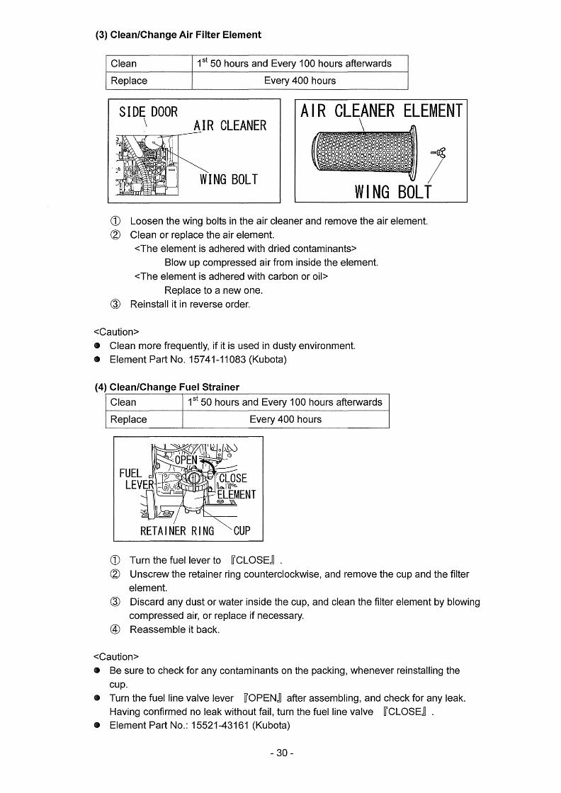
(3) CIeanlChange Air Filter Element
Clean ISt50hoursandEvery100hoursafterwards
Replace Every400hours
SIDE x
DOORAIR CLEANER
.
.
]b nv
WING BOLT
AlR CLEANER ELEMENT
WlNG
,jiiiiiiiii
BOLT
(iD Loosen the wing bolts in the air cleaner and remove the air element
@ CIean or replace the air element.
<The element is adhered with dried contaminants>
Blow up compressed air from inside the element.
<The element is adhered with carbon or oil>
Replace to a new one.@ Reinstall it in reve rse order.
<Caution>
g Clean more frequently, if it is used in dusty environment.
pt Element Part No. 15741-11083 (Kubota)
(4) CIeanlChange Fuel Strainer
CIean ISt50hoursandEvery1OOhoursafterwards
Replace Every400hours
FUELLEVER
llil s(i ti
-OPEN
o .o:3stlva
llil3ii#siiiiiiiN>
llllllii-l7,,l.-------'
地esE
LEMENT
ETAINER lNG UP
D Turn the fuel lever to ifCLOSES .
Unscrew the retainer ring counterclockwise, and remove the cup and the filter
element. Discard any dust or water inside the cup, and clean the filter element by blowing
compressed air, or replace if necessary.
Reassembleitback.
Caution>
Be sure to check for any contarninants on the packing, whenever reinstalling the
cup.e Tu rn the fuel line valve lever ffOPENg after assernbling, and check for any leak.
Having confirmed no leakwithout fail, turn the fuel Iine valve ifCLOSEg .
e Element Part No.: 1552143161 (Kubota)
30-

(5) Drain Water from Fuel Tank
Drain Water Every 200 hours]ta e
o
o
=]
ll
QeeceO#
FUEL DRAIN PLUG
(l) Unscrew the fuel drain pl ug.
@ Reinstall the drain plug, after draining water completely
<Caution>
e Change the packing, whenever changing oil.
g Packing Part No.: 6C090-58961 (Kubota)
(6) ChaRging CoolanttWater
Replace Every 2 years or 2000 hours
(Total Coolant/Water Capacity: 4.3 Iiter, including sub tank cap. O.6 liter.)
RADIATOR CAP
TOP PLATE XXi,,,,
gesssses
WATER INLET
/SIDE DOOR
:
Ob
m
l OeeOoe SUB TANK
WATER DRAIN PLUG
(i) Open the top plate.
@ Removetheradiatorcap.@ Loosen the watGr drain plug .
@ Afterdraining all thewater, reinstall thewaterdrain plug.
<Caution>
e Changethepacking,wheneverchangingoil.
e Packing Part No.: 6C090-58961 (Kubota)@ Replace all the water in the $ub ta nk.
@ Fill the coolanUwater to the MAX level (to the upper edge of the inlet).
(ll> Reinstalltheradiatorcap.
@ Close the top plate.
-31-
Q Danger : Electric Shock
pt Before performing any equipment check or maintenance, stop the engine,and
remove the engine key. A person performing the maintenance should always
keep the key.
A Caution:lnjuries
g Before performing any equipment check or maintenance, stop the engine, and
remeve the engine key. A person performing the maintenance should always
keep the key.
A Caution:FirenBums g When checking engine, always stop the engine, and keep far away from fire.
femperature around murner and exhaust can get extremely high. Wait until the
engine cools down, before performing any checks.
If the generator/welder will not be used for more than two months, petform the
following maintenance and storage procedures.
O Removethebattery. @ Changetheengineoil. @ Drain fuel from the fuel tank and the fuel strainer.
@ Clean all parts, coverthe generator/welder, and keep it in the storage, away
from dust and humidity.
<Caution>
g Recharge the removed batte ry once a month .
GXIiiliijiEll
O Danger : Electric Sheck
g Do not operate the equipment, if the equipmen{ or you are wet.
Before performing any equipment check or maintenance, stop the engine.
A Caution:lnjuries
e Whenperformingequipmentcheckandmaintenance, always stop the engine.
A Caution:FireiBums e When checking engiBe, always stop the engine, and keep away from fire.
femperature around engine, muMer and exhaust can get extremely high.
Wait until the engine cools down, before performing any checks.
Follow the guideline below, when performing any troubleshooting. If you cannot
re$olve the problems by this troubleshooting guide, contact the authorized distributor
or our engineering section to request the repair.
-- 32 -
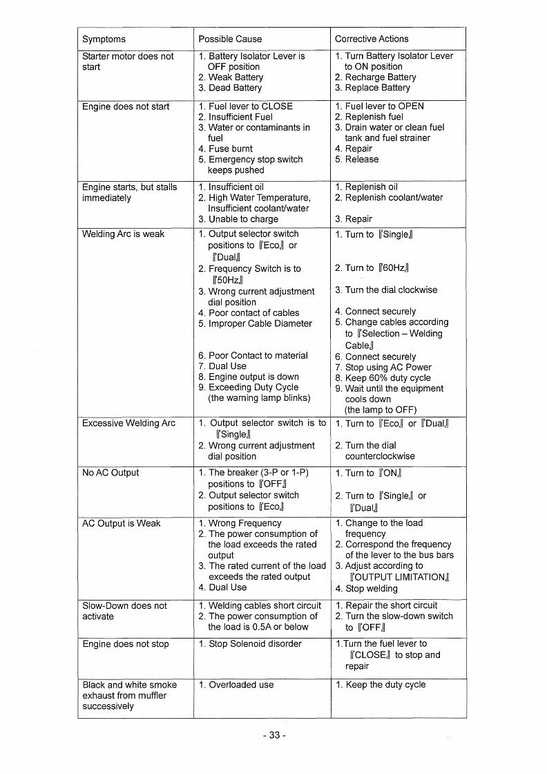
Symptoms PossibleCause CorrectiveActions
Startermotordoesnotstart
1.BatterylsolatorLeveri$OFFposition
2.WeakBattery3.DeadBattery
1.TurnBatrterylsolatorLever
toONposition2.RechargeBattery3.ReplaceBattery
Enginedoesnotstart 1.FuellevertoCLOSE2.In$ufficientFuel
3.Waterorcontaminantsinfue1
4.Fuseburnt5.Ernergencystopswitchkeepspu$hed
1.FuellevertoOPEN2.Replenishfuel3.Drainwaterorcleanfuel
tankandfuelstraiBer4.Repair5.Release
Enginestarts,butstalls
immediately
1.Insufficientoil
2.HighWaterTernperature,lnsufficientcoolantiwater
3.Unabletocharge
1.Replenishoil
2.Replenishcoolantiwater
3.Repair
WeldingArcisweak 1.0utputselectorswitchpositionstoifEcoSorifDualS
2.FrequencySwitchistotr50HzS
3.Wrongcurrentadjustmentdialposition
4.Poorcontactofcables5.ImproperCableDiameter
6.PoorContacttomaterial7.DualUse8.Engineoutputisdown9.ExceedingDutyCycle
(thewaminglampblinks)
1.TurntoffSingleg
2.Turntoif60Hzg
3.Turnthedialclockwlse
4.Connectsecurely5.Changecablesaccording
toifSelectioB---Welding
CableS
6.Connectsecurely7.StopusingACPower8.Keep600/odutycycle9.Waituntiltheequipment
cool$down(thelamptoOFF)
ExcessiveWeldingArc 1.0utputselectorswitchistoifSingleS
2.WrongcurrentadjustmeRtdialpesition
1.TurntoifEcoSorffDualg
2.Turnthedialcountercleckwise
NoACOutput 1.Thebreaker(3-Por1-P)positionstoifOFFS
2.0utputselectorswitchpositionstoTEcoS
1.TumtoifONS
2.TurntoifSingleSorifDualS
ACOutputisWeak 1.WrongFrequency2.Thepowerconsurnptionoftheloadexceed$theratedoutput
3.Theratedcurrentoftheloadexceedstheratedoutput
4.DualUse
1.Changetotheloadfrequency
2.CorrespondthefrequencyoftheIevertothebusbars
3.Adjustaccordingto
ffOUTPUTLIMITATION£4.Stopwelding
Slow-Downdoesnotactivate
1.Weldingcables$hortcircuit
2.ThepowerconsumptionoftheIoadise.5Aorbelow
1.Repairtheshortcircuit
2.Turntheslow-downswitchteffoFf:g
Enginedoesnotstop 1.StopSolenoiddisorder 1.TurnthefuellevertoffCLOSEStostopand.repalr
Blackandwhite$mokeexhau$tfrommufflersuccessively
1.0verloadeduse 1.Keepthedutycycle
-33-

臨 ω 駆 舞
購RE
COLOR
Lock
賢hite
狸ed
Gpeen
Yeしし。“
Bro冒
n
日ωe
C{〕し{}R5
CODE
陪
H
R
6
Y Br
L
WAτER マ巳雑P.
SW【
γCH
O乳L
PR巳
5S.
S田τC8
ENERGENCY
STOP
しiφ
紅Gree
nし
9SWITCH
OP㎝9¢
OrGr
eGp
唾 讐
R
G4
窪 驚o;
o@
日/冒
・祠
門OM
下0只
しAN
P
@ (PR
粟NT
ED C…
RCUI
T)
ニ18・
・AR
G・p悲
。・
・E旺
A・。
V晶T
亭 し
2ト
L/
疑
1r「
1、/
騨1
W/R
唱
冒曾
勧 7 u u ワ曾
曾…
Gr
Ll
o・4
1
@ 2
b卜IARG韮NG
3
fEN往
RATO
R
”/G
l R
朝Gr
卜 臼/冒
・制
毒毒
(,
Y r O「
2} R
FUεL
sANK
しFU
EL
fAUG
E
. ●一● Bp
1σ-
軒
「』
猫、
一D
}1
ぴ
TIHER
R
5 4
6襲 B5 Y
L
IG
ヲ Bン B
L8
8rG
ラ Y3 し
燃
乳8r
2
P晩L
gOLD
Y 『
3 Y 「
t 「m→
1監
塞 3 「
門卿
Lコ
糟 一G紀
NERA
丁OR
WI
RING
D1AGRAN
@ Y
… 8」 Y一 R
Bξ
R●
LY
BBp
GrR婁 し
3 Y
(+
1)
i一1)
i+2)
・
i一2)
Y」
YG吟
「
しノ
樟一 只
「
冒
一
Y F U s E ( 2 0 A 〕
R
~8P
RB
B L
B/R
/B
B/野
「「
,7
咽,
OrD
L
,「
,「,
,
{7
RL
YR
,
7 8 3 1 馨 5 4 9 … 2 1 0 E 颯 E R G E N C Y R E し A Y 3 韮 4 2
1「
1■
RB 畜R 斎
獄
6
@ GLOW Pし
UGX3 SLO閥
0閥N
NY 竃
舅 R 1、
臼 護 \ , , A R , E R
・竃
⊆
溺σ0 ACb
S粥TCH
」∠
S畷c日
曾
F
)
HOUR
E丁εR
受,
圭Gr
〉 甘鼻 ”
し
R
瞥7一
7一匿
R
「
冒
/8
WB
R Fu
s旺
@(50
A)
8
{
B 聖 8 B A τ τ E R Y l $ O L A τ O R > ・ B ’ Y ヲ Y 一
§1
“
k{1醒
RVV
哲AG
NETl
C
r田τCH
@
STAR
TER
SW工
TCH
CONN
εCτ
10N
●
5下A決
T}NG
rWITCH
30蔑9
ACSO
一h
1
.$ d 7
SτOP
01
1
8ATT
ERY
RUN
00
PO
翼εR
CGNTROし
しE2
iGE三
NERA
τOR
W夏
RiNG
9韮
AGRA
穫)
冒一
PRε目EAτ
(〉
〈}つ
SγAR
T(〉
〈〉ひ
ゆ
RELAY
R巳LAY
Sτ
OP
SOしEN◎lD
繊 恥 田 8 o §

- ω O -
冨
Y/降
.
rl
謎
Y iii
GεN葺
RAτ
OR
V(】
しr《
GE
`DJり
5τNENT
DIAL、
hELD…NG CURRE断
薩3
γ!備iti
離
㌧u
}欄
?ヲ旺
卜le
τE
CGN獣
α.
E…脚
し・
,、
㈱、
麟(
氏>
R關
OT巳
c斜τ
ROL韓
◎X
50
L巳NO
m
薩毒
騨y/R
差
鞭
阿/も
轡 働 一酸
一冒
・ヨ鵬
P摂職
(OP
τIG
罠}
ャ 「……}馳…一i
甘/解
VRO
r舐しECτIG踵
T聚HCH
PR
蝦τ
εDC
琳C膜
τ@
〔
LFO
DIsP【
.AY
)s
じ
日
u、…熱45巳7臼
、馨竃2コ
4567ε9「
戴!黙1了認了覇詩89
1。粥2猟
丁薩
琿瞠
u/冊
貿/窟
まF
_}
c
恥ノ∬
㍉捧瀞L
瞭鰻職
lL照
Ll阻
し}
言
}{{]}.卜__■■_L凹
_曹r_
_rr_.幽_國り_」
醸
G淑ε
絹RiNG
@ 樹
ゑGRA図
x1,
胃45δ
?超
tL慧
3朽67聾
総鰻烈巴」黛賦屡9蹴
u2B1
4」τR細
SFαモ潔ER
L省諭
_差 7凱 「
に蘇
闇閲
差一}
…欝
二 冒畳 喜二 〇
∀
7 塁雲ご 一一
霧睡
A
c
鐸
P臼
1黙
ED
CIRCU
Στ
@
(し
鱒CO
博RO
De
3
に
5冨蓄著ぎ姜
験票
rぎ罫……ぎ
汗 8i…
r534
56ア
冒m
r匙欝
16憾
6靴ぼ欄i
¥
……
…
〒 ∋ 1 襲 一 一 雨
L鷹懸.乙、ロ30
9 }
01=
_」
L 鳳 乱 5 6 7 」 職14
諺
萄12
蓉57
1。_臥1
”
峯ド
=響ぎ
〒∋1∈M Y 瀞 虞
言
L ・ V ノ 聡隻 睡
孟 しc
颪
@ PG既R
c鋸TRoし
LεR
テ
9
(PRぎ
誕τ
〔B
crRCU罫
了)
臼
F
1い28
76器・㎜ノ
旨η75
54 i2
3目5
騒
9
冨
21
;5精
:o=
116
鰐ボ三簾1
さ一
R〆Y
一竃量量
三 婁馨
聖き 墨礁
恥 量量と基
甘 蓋亀
竃蓑 寒璽
二ビ_一珊 ミ量茎差;卑量茎竺
暑二距
Yと ,馨
【
一遮
?c1
x 諭 R
勢巳 ア
壁モ
一=
冊薦.
ゐ・
…麗
!陰
一へ
…
狐 R 臼L
冒
ひノ
臼
暑冒琶
巳N{
}i隈
矯RI糾
G
@ 購AGRA耗
P/冨
0構P田
@ S叢
ぼCT
OR@
5剛τ
C卜1
kcv-
cc[
CR言5P
1-Cc
£sO
Fη)
㌻菅裟署
R鞍≧
冠髪
阯緊鴬睾砦ヒ
日
し/ソ
1土
萎l
撃狽R
Tし騨一DO襯
п@s購
儒j阿。NmR LA呂P
R-P卜
IASE
qFCFPTACI.
E
@
㌦
贈用「「1紳
〆駐
/し
一靴/Y
L聾
4・照
w隙串 強 . 4
賊5i57σ
騎(
2Jk籍
,
畢恥舗直肋
{ 3嘆
…『
一『
…
一一
i
簾㎜瓢
Rξs工
5了o舜
オ〔!’恥x
w)語
竃絹
飛
宅障貿
餅臓警
噺肝蓋
L≧
冒髪
一 丁 一 π
璋
。F
B簾
oτ工
劉黙
掛 酔 c T 轟
1覇
器毛
響
1著芸
勘v善
‘v
@ ,
@ L
C【け
l
L
器:
〔_
㎜…
…』
}
㎜㎜
罵_
摩STATOR
「…揃…「
Al i,
●鳳」
1に3・τ 一
翫し
ζ欝
〔AW}
ビ ξ
R I
篠.
証鼎
整c晒
曜
冨 Y
驚R鴛
c鷲F斑
軌
G3
東病
畳1…
一 ヤ }
し
L
l
一一
一騨
怐@
画型R醐
黷
聴 冒財 理
Yv
曾 図
i 饗 塞
: 1 で : 1 目 隆 乎
蝿津
珊YR
[SτG険
閑L
、葦
、
轟婁 書葛 欝
鐸r Or
B 櫛 販 c 了 : F 且 E R 一 「 騰 靴
R > 一 B
栂眺 辮 「 、
1 「 引 . . _ ~ 。 1
脚扇
RRA.
亟_
_i
q。lo甫… 『………』一
qEσEFI臓
1田)
しw塁
踏壇為
㎜罰
i
R慈c7F円
嚴R
@9
詰 , 3 / Y
一雌
i 1 至 融


Shindaiwa Cowpowatien
Head Office : 6-2-11, Ozuka-Nishi,
Asaminami・-ku,Hiroshima 731 -31 67,Japan
folephone : 81-82-849-2220 F/V>< : 81-82--849-2481