Embed Size (px)
Citation preview
!"#$ " %& "#
! "#$""!"
%""! "&
" " "
# "'()*! "+
,-&&"%%.!"
$'-%%.*!&""&! -
!-!"
-&
,-
-&!'*
%
#%&'(#)'* &
* + "&,-"% "#.
(%""" ""/!""" "0/!/-/ /"
/ (1',2*
%! 01
- ! &"&! &("3-"""
&)&#
! +"""#1245)
/ (',5*
+ 23!!)4',5# #'* -#,* 2
$"&!&"!,5/""&! / + &
/ (6'57*
,,5&
5787%%.""! &"""& & %%. ! "!& %%.!""&-,%87
/ (88'57*
9
"#$ "#%
!,
(! +:/ " / & !"- "
6 $ ,2
" " " " , " !/ "+ "/ ! " 3
!-&#&'2,-&$ #
" " +"&
6# $!&
6# $.#!& +
2
.0.
60$'!-%%.*
0
;01!'*
0 $'
7+0(
0
7 2
,05)"&
8
0 "4 " ' *
10
!
<$0 <
<$4$04<
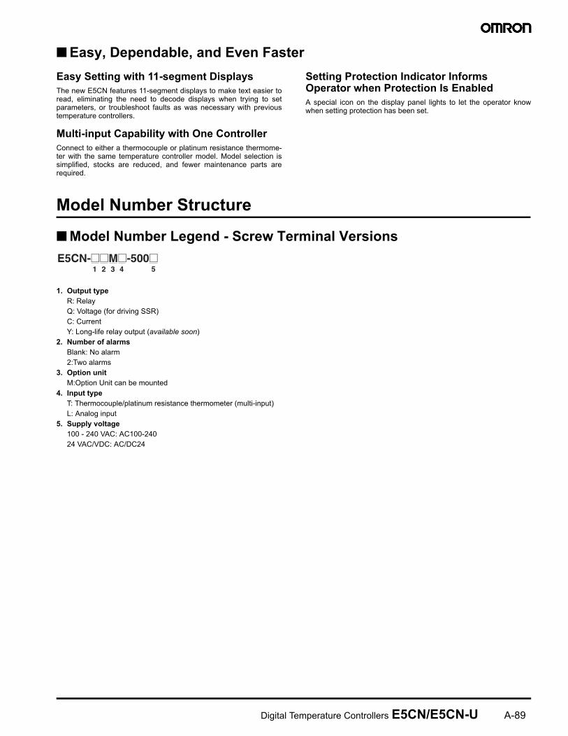
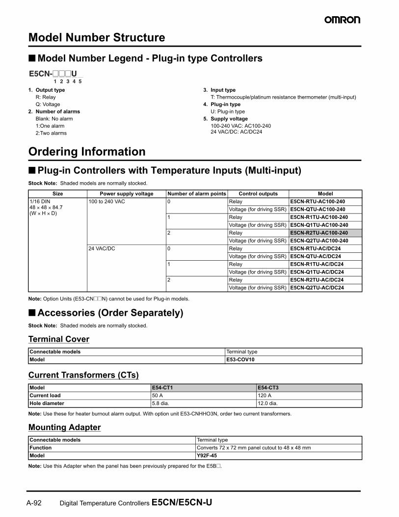
1 2 3 4 5E5CN-@@M@-500@
9
2#'
,36 4!&9/% "+
'=*-&
,* !&9/% "+
'=*-&
!: - $' 6#
4 >2(<× <× ?'@× 8× *
<$ . )611*11081
$'!-%%.* ;611*11081
611*11081
. )0611*11081
$'!-%%.* ;0611*11081
0611*11081
1! <0611*11081=
<$4 . )611*08
$'!-%%.* ;611*08
611*08
. )0611*08
$'!-%%.* ;0611*08
0611*08
1! <0611*08=
!: - $' 6#
4 >2(<× <× ?'@× 8× *
<$ . )6.11*11081
$'!-%%.* ;6.11*11081
6.11*11081
. )06.11*11081
$'!-%%.* ;06.11*11081
06.11*11081
1! <06.11*11081=
<$4 . )06.11*08
$'!-%%.* ;06.11*08
06.11*08
9
2(-!"!!5)
!&9/% "+
/ 5)"&!()# 5)"&!(
%& 6#
"A8&A%%.!" 7517
" 717
"A8&A%%.!"A- 75
- 7
"AB&A%%.!" 75517
"A'-* 7;17
"A8&A%%.!"A'-* 7;5
CT1
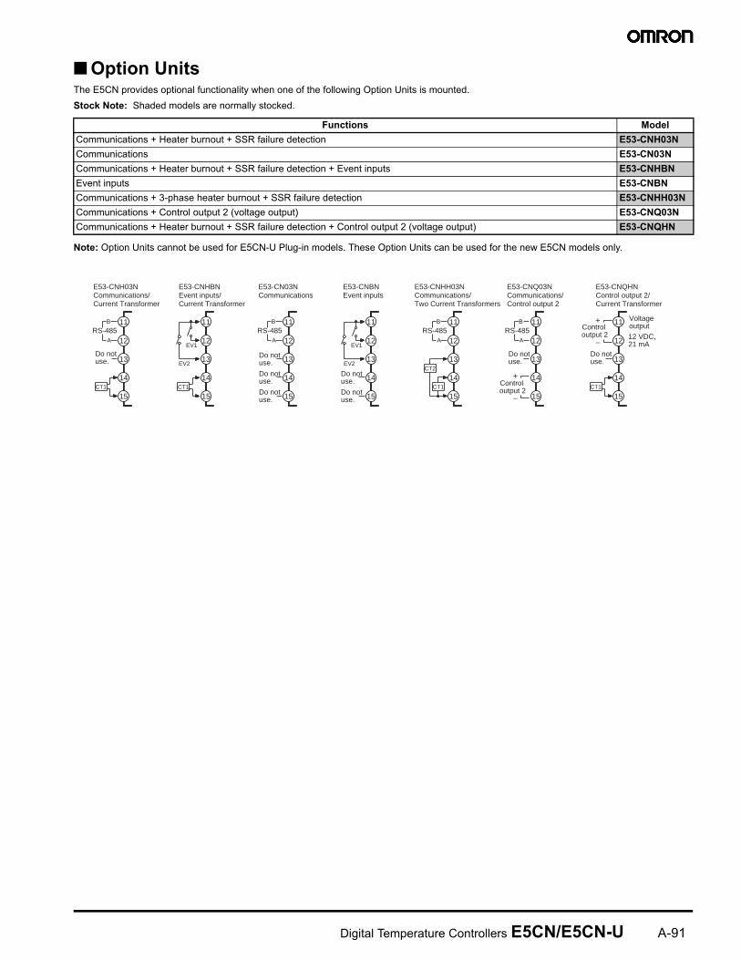
E53-CNQHNControl output 2/Current Transformer
−
+
12
11
15
14
13
E53-CNQ03NCommunications/Control output 2
−
+
B
A
RS-48512
11
15
14
13
E53-CNHH03NCommunications/Two Current Transformers
CT2
CT1
13
14
15
11
12
B
A
RS-485
E53-CN03NCommunications
Do notuse.
Do notuse.
Do notuse.
Do notuse.
Do notuse.
B
A
RS-48512
11
15
14
13
E53-CNBNEvent inputs
EV1
EV2
12
11
15
14
13
E53-CNHBNEvent inputs/Current Transformer
CT1
13
14
15
11
12
EV2
EV1
E53-CNH03NCommunications/Current Transformer
CT1
13
14
15
11
12
B
A
RS-485
Do notuse.
Do notuse.
Do notuse.
Control output 2
Control output 2 12 VDC,
21 mA
Voltage output
9
6# $!&
6# $.#-
2
.0.
60$
0 $'
7+0(
05
0
7
0 "4 " ' *
8 -
)0#
!
<$0 <<$404<
2#'
- ,36 4!&9/% "+
/ 5)'B((*"&!#
*&&32#! 4!&9/% "+
'34
/ )!& @B(885B(/"!
6*#
/ )&-!7
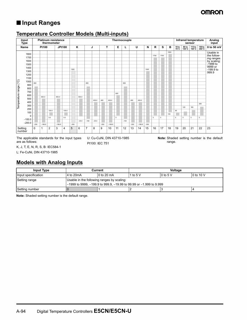
1 2 3 4 5E5CN-@@@U
!: - $' 6#
4 >2(<× <× <?'@× 8× *
<$ . )*11081
$'!-%%.* ;*11081
. )*11081
$'!-%%.* ;*11081
. )0*11081
$'!-%%.* ;0*11081
<$4 . )*08
$'!-%%.* ;*08
. )*08
$'!-%%.* ;*08
. )0*08
$'!-%%.* ;0*08
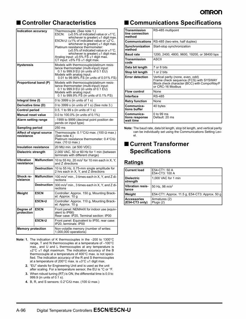
&$ #
6# 72+1
6# 8 87
#
5 #
&$ #
%& -?:? "<:<
6# <>0%8
9B
!&93'- &6# 4
!&'&
)
6# -0% -0% -7* <>0*8?
""%"+
7 !""+ /"
""%"+#"
7 !""+ /"
7"+"""+
7"+ /!;9B /& "
-!#"
#BC
-
11081+*"115: 08+*"115:08+
2 D D!-
-&
?$ :'(.0B$ $* $4B@ :'(.0?$<$*
>$ : B$4@ :
! ,
"0E/F///1/)/(/./%/7
# " 0# F#
2! 0 ?°/> °/ >°/ >>°$0 $
,
0<
$0 $/$/ $
#& 0 Ω/$0 ,Ω') 0 """"%87*
) ( %#%(5/$/B'-*/""!0 // "&0$/
() %#/$/B'-*/""!0 // "&0 $/
+ (()
5-0 $± D'#(#*/ :"0 /"""""
( < 4 /0>Ω :/0:/?
. '
( %#%(5/$/B'-*/""!0 /// "&0$/ '""*
* %#%(5/$/ '-*/""!0 // "&0 $/
& 5(0 +Ω :/50 +Ω
&&
5(0.-0 $ :/501+"0 :
5!"0:?
,# 5(45"#2"'*
!,# !+
#&,# -"'? &*
"0#$0 /%$0>
2,'& ,/4""/!' */&+ / %#/,$ /!/!/ !/4/"!"/"
*$
− °'""*/!B0− °
*$,# DD
! −>°'""*
9<
)
6# 36 4
6# ,*
/ % &!
- &,
,& '#
*
-11 @-11 A @ . ) ! 1B1°
101°
°
101°
11+
?
>
<
B
9
?
>
<
B
−
−
)&!&"0 9999999 9999999
? ?
B B
>
< < < < <
>
>
9
− − − −
− − 999 − 999 − − − 999 − − 999 −
% &
B < > ? 9 B < > ? 9 B
'
°*
"& ! !0
E/F///(/./%/702<
10(/2(<B? 9
)0(/2(<B? 9
# 02?
/ % & !
+
2"!" < $ $ $
% )&!&"0
− 9999999/− 9999999/− 9999999− 9999999
% & B <
9
* %" ! !&
/ @- /</ -"&!" /:G1HG8H
0 %-0 /)
7 %-0</)
8 %-0/) &3")11 "&&-
C 5 -
C B05
%-0/) &3"5 -
%-0 /17+ "&!
% ! B-!' *
! * *
(,D
(,D
!"5 55
'% *
)
'%*
)
B 1
<'% *
)
'%B*
'% *
) &3"
'%*
'%<*
> ) &3"
? 1 &3"
&-
9 &-
&- &3"
&- &3"
'%>*
17+ '! *
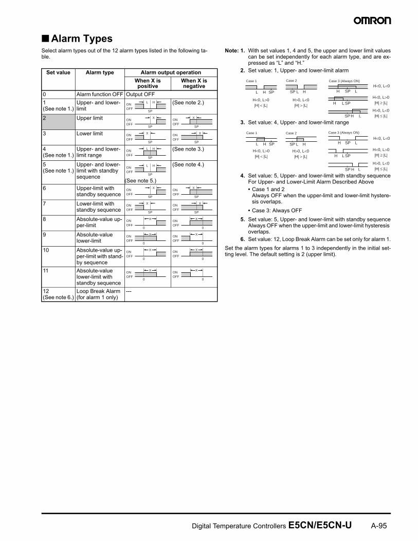
ONOFF
SP
L H
SP
XONOFF
SP
XONOFF
SP
XONOFF
SP
XONOFF
SP
L HONOFF
SP
L HONOFF
SP
XONOFF
SP
XONOFF
SP
XONOFF
SP
XONOFF
0
XONOFF
0
XONOFF
0
XONOFF
0
XONOFF
0
XONOFF
0
XONOFF
0
XONOFF
0
XONOFF
L H
H<0, L>0|H| < |L|
SP
Case 1
L H
H>0, L<0|H| > |L|
SP
Case 2
LHH<0, L<0
SP
LHH<0, L>0|H| ≥ |L|SP
LHH>0, L<0|H| ≤ |L|SP
Case 3 (Always ON)
L H
H<0, L>0|H| < |L|
SP
Case 1
L H
H>0, L<0|H| > |L|
SP
Case 2
LHH<0, L<0
SP
L
L
H
H<0, L>0|H| ≥ |L|SP
H
H>0, L<0|H| ≤ |L|SP
Case 3 (Always ON)
9>
,&&
/ "!E " − B°/( " !− ° :/ ) 1 " ±°± : """"! 7 " !<° :"!""""!.% " !° :±B°± :
0 G)H!)!" /)°°
7 @&'.*5(/!! 9999'! *
8 7/./%0°4Ω :' Ω :*
&!&'&
/ &/&/&/-""&- "%1-
'
!&'&
)
#&&&& "0'% *(0 '±D!"-± °/
"-*± :()0 '± D!"-±°/
"-*± :# " 0
'±D!"-± °/"-*± :
0±D%± :0±D%± :
5 , "4 " ' *0 9999)'! )*
,0 9999D%'! D%*
- $#3-4 , "4 " ' *0 9999)'! )*
,0 9999D%'! D%*
34 B999'! *
34 B999'! *'%B*
# / 99'! *
6 D'! D*
* − 9999999'" *
! #
*''&' &&
"0 °4Ω :' Ω :*'%<*# " 0<°4Ω :' Ω :*
& ,Ω '$*
&&, /$/>8I! '& !!"*
+$&
6 '& 8I/ 4! "J/;/K"
& 8I/? ! "J/;/K"
!,&9&
6 '& 4 /B "J/;/K"
& B 4 /B "J/;/K"
(, 0: /,7"+0:
0: /,7"+0:
'&
0(,<J!'3-2#>>*."02#/ "02#
03-2#/"02#/ 02#
6 & (- ' &!0 //*
&&,#
.%<
& .%<'/!:*
! &,:,#
%"I
# /</</9>/ 9/B<&
&#
%22
$ , ?&
!$ , &
#& $"'/-/* ""+3"'%*%;%@;7"+""+""'7* @4. >,&
% & (
'& .%<
) '& (
&$''
<&
&
99 !0
# < 0<B0
&&,
/$!
+$&
8I/9 4
(, < 0: /<B0:
*&&387 4
'*#'*
9?
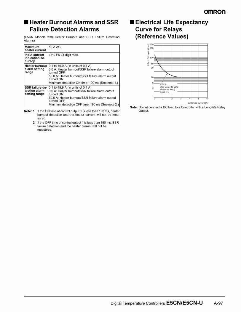
5* #!!)
% &* '( , 8 7 %%. " *
/ 2!5( !" 9 /&" "&
0 2!5 !" 9 /%%.!""&
&& .'E&&
')
3)'&+ 4
/ ""1!.5
6E,&
&#&&&&
±D%± :
5$
<99'! *08&4%%.! 508&4%%.! 5(, "5( 0 9 '% *
!!)' #&
<99'! *08&4%%.! 5(08&4%%.! 5, "5 0 9 '%*
500
300
100
50
30
10
5
3
10 1 2 3 4 5 6
Switching current (A)
Life
(×
104 o
pera
tions
)
E5CN250 VAC, 30 VDC (resistive load)cosφ = 1
9
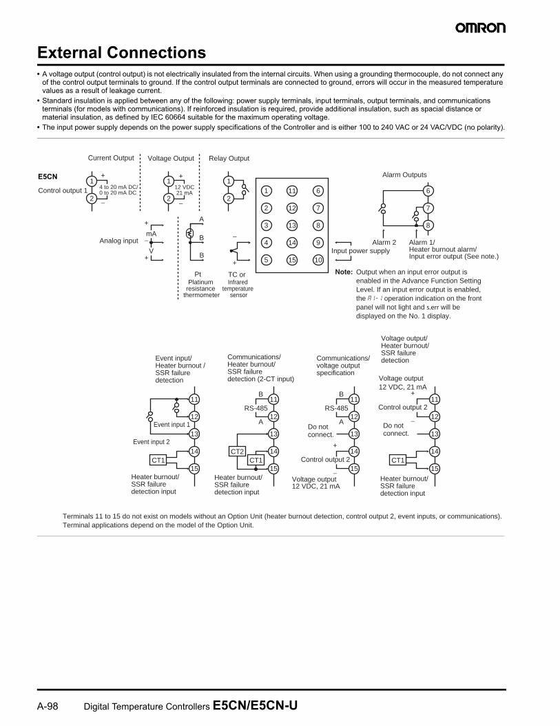
E &C -'"*""! ""@ "/""!" 2!" ""/"" -!+"
C %&!!0 / / /" " '! " "*2!!"3/-/""" /!&2>>><&! : -
C "!"! <$<$4$'*
Relay OutputVoltage Output
Terminals 11 to 15 do not exist on models without an Option Unit (heater burnout detection, control output 2, event inputs, or communications).Terminal applications depend on the model of the Option Unit.
−
+
+
−
+
Alarm Outputs
Control output 1
Alarm 1/ Heater burnout alarm/ Input error output (See note.)
Alarm 2Analog input
Current Output
Infrared temperature
sensor
Communications/ Heater burnout/SSR failure detection (2-CT input)
Platinum resistance
thermometer
Communications/ voltage output specification
+
−
Do not connect.
Voltage output/ Heater burnout/SSR failure detection
+
−Do not connect.
Event input 1
Event input 2
Event input/ Heater burnout /SSR failure detection
Heater burnout/SSR failure detection input
Heater burnout/SSR failure detection input
Voltage output 12 VDC, 21 mA
Heater burnout/SSR failure detection input
Note: Output when an input error output is enabled in the Advance Function Setting Level. If an input error output is enabled, the a1-1 operation indication on the front panel will not light and s.err will be displayed on the No. 1 display.
6
7
8
9
10
11
12
13
14
15
1
3
2
4
5
11
12
13
14
15
B
Pt TC or
A
B
B
A
V
mA
6
7
8
1
2
1
2
1
2
RS-485
CT1CT2
11
12
13
14
15
B
A
RS-48511
12
13
14
15
11
12
13
14
15CT1 CT1
−
+
4 to 20 mA DC/0 to 20 mA DC
−
+
12 VDC21 mA
Input power supply
Control output 2
Voltage output12 VDC, 21 mA
Control output 2
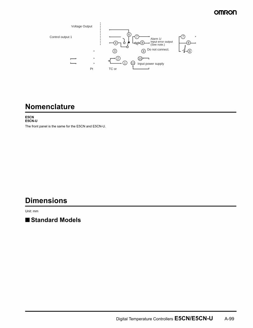
99
&
! !(()
)0
!##6#
7
8
9
10111
2
3
4
6
Voltage Output
Pt TC or
Alarm 1/Input error output (See note.)
Control output 1
Input power supply
Do not connect.
7
8
9

*&&
'3! #! 4
6
14.2
58
7085
48 × 48
4488 × 44.
8
Mounting Adapter
(Accessory)
60 min.
(48 × number of units − 285)
+1.00
45 +0860
45+0860
Panel Cutout
Mounted Separately
Group Mounted
45
+0860
- 6 #
C . " " +
C C &
-""',"
! "&
*
C @
/ +
: " &
"!"!"
48
48.8
22
981
72+1
/ !!:GH &!"-B5$ -
30
1502503 0430210502.80210Two,7 .5 dia.0
40 × 4030121dia.928367dia.1530Two, M3 (depth: 4)Approx. 3 dia.
18
(22)Approx. 6 dia.PlugArmature
Lead
8 7
8 7 * & &
C *
C - & E

*#
/ )"-?:? "<:< "
(!&93! #! 4
/ !"'# *-&
/ )"+-!!"""")"!"+
0 #"--!!"';9<C*-&
Fixture (Accessory)
69.6 to 77.6
87
72 × 72
764.7
67 × 67
<>0%8
Panel (1 to 8.mm)77.3 (to back of E5CN)
72 × 72
48. × 48
2.2 4.7 6#40 ± 0.24.55678432191011
70 max.
4
Eleven, M3.5 × 7.5 sems screws
7.8Two, 4.5-dia. holes50 max. 3
31.2 max.
35.4Note: Can also be mounted to a DIN track.
Mounting HolesTerminal Layout/Internal Connections (Top View)
Two, 4.5 dia mounting holes%−&−&!−&9-0φ%5 6 7 8
4
3
2 91011 1
25.627 dia.
45
45 4.5 16.3 6.2 4 7 38 . 7 6
T e r m i n a l L a y o u t / I n t e r n a l C o n n e c t i o n s ( B o t t o m V i e w )
&9&−&!−&9-7*
2
2 '2-&#! -3-"!"-"&-% &""""! --L
/ 5-!!
0 ;" --&+!! "&-; 5
7 ;" --&+!! "-
8 + -"-"&M&"G,-"- H
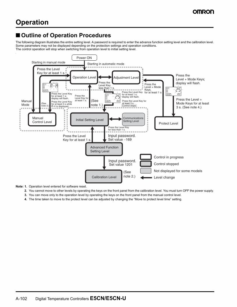
Input password.
Input password. Set value 1201
Control in progress
Control stopped
Operation Level
Not displayed for some models
Level change
Initial Setting Level Communications Setting Level
Adjustment Level
Protect Level
Power ON
Press the Level Key less than 1 s.
Manual Control Level
Press the Level Key for at least 1 s.
Starting in manual mode Starting in automatic mode
Manual Mode
Press the Level Key for at least 1 s.
Press the Level + Mode Keys. for at least 1 s
Calibration Level
Press the Level + Mode Keys; display will flash.
Advanced Function Setting Level
(See note 1.)
(See note 2.)
(See note 3.)
a-mC
25100
C
25100
C
Set value −169
Press the Level Key for at least 3 s while a-m is displayed.
Press the Level Key for at least 1 s; display will flash.
Press the Level Key for at least 1 s.
Press the Level Key for at least 1 s; display will flash.
Press the Level Key for at least 3 s. Control stops .
Press the Level + Mode Keys for at least 3 s. (See note 4.)
Press the Level Key for less than 1 s.
B
-
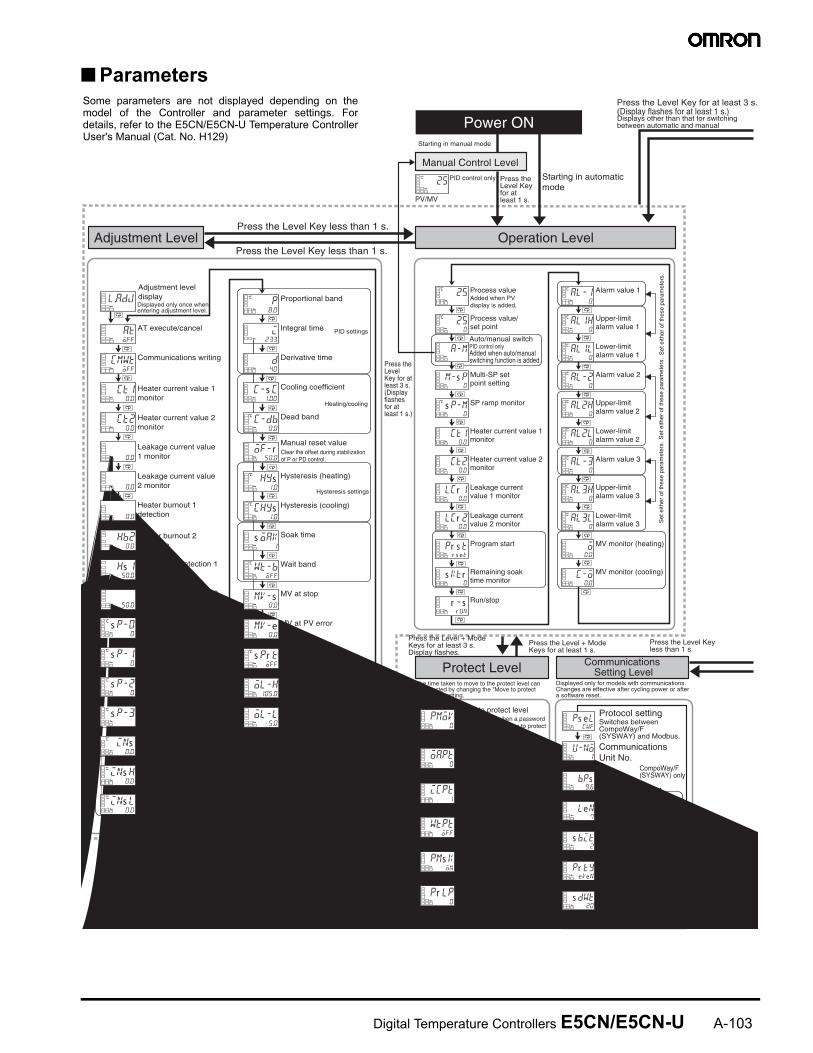
Operation Level
Manual Control Level
Power ON
Adjustment Level
Protect Level Communications Setting Level
a-m
m-s p0
25C
250
C
s p-m0
C
ct10.0
ct20.0
lcr 10.0
lcr 20.0
pr s tr s et
s ktr0
r -sr un
al-10
C
al1h0
C
al1l0
C
al-20
C
al2h0
C
al2l0
C
al-30
C
al3h0
C
al3l0
C
o0.0
c-o0.0
Process valueAdded when PV display is added.
Process value/ set point
Multi-SP set point setting
SP ramp monitor
Heater current value 1 monitor
Heater current value 2 monitor
Leakage current value 1 monitor
Leakage current value 2 monitor
Program start
Remaining soak time monitor
Run/stop
Alarm value 1
Upper-limit alarm value 1
Lower-limit alarm value 1
Alarm value 2
Upper-limit alarm value 2
Lower-limit alarm value 2
Alarm value 3
Upper-limit alarm value 3
Lower-limit alarm value 3
MV monitor (heating)
MV monitor (cooling)
cmwtoff
ct10.0
l.adj
atoff
ct20.0
lcr 1
0.0
lcr 2
0.0
hb1
0.0
hb20.0
hs 150.0
hs 2
50.0
s p-00
C
s p-10
C
s p-20
C
s p-30C
ins0.0
C
ins h0.0
C
p8.0
C
i233
d40
c-s c1.00
c-db0.0
C
of-r50.0
hys1.0
C
chys1.0
C
s oak1
wt-boff
C
mV-s0.0
mV-e0.0
s pr toff
C
ol-h105.0
ol-l-5.0
AT execute/cancel
Communications writing
SSR failure detection 1
SSR failure detection 2
SP 0
SP 1
SP 2
SP 3
Temperature input shift
Proportional band
Integral time
Derivative time
Cooling coefficient
Dead band
Manual reset value
Hysteresis (heating)
Hysteresis (cooling)
Soak time
Wait band
MV at stop
MV at PV error
SP ramp set value
MV upper limit
MV lower limit Protocol setting
Communications Unit No.
Baud rate
Data bits
Stop bits
Communications parity
Send delay
ps elcwf
u-no1
bps9.6
len7
s bit2
pr tyeVen
s dwt20
pmoV0
oapt0
icpt1
wtptoff
pms kon
pr lp0
Move to protect level
Operation/adjustment protection
Initial Setting/ Communications Protection
Setting change protection
Parameter mask enable
Password to move to protect level Password setting
Press the Level Key less than 1 s.
Press the Level Key less than 1 s.
Press the Level Key for at least 3 s.(Display flashes for at least 1 s.)Displays other than that for switching between automatic and manual
Starting in automatic mode
Starting in manual mode
25C
PV/MV
PID control only
ins l0.0
C
SP used by multi-SP
Set either of these parameters.
PID settings
Heating/cooling
Hysteresis settings
1-point shift
2-point shift
CompoWay/F (SYSWAY) only
Auto/manual switchPID control onlyAdded when auto/manual switching function is added.
Set
eith
er o
f the
se p
aram
eter
s.
Press the Level Key for at least 1 s.
Adjustment level displayDisplayed only once when entering adjustment level.
a
Heater current value 1 monitor
Heater current value 2 monitor
Leakage current value 1 monitor
Leakage current value 2 monitor
Heater burnout 1 detection
Heater burnout 2 detection
Upper-limit temperature input
Lower-limit temperature input
Clear the offset during stabilization of P or PD control.
Press the Level Key for at least 3 s. (Display flashes for at least 1 s.)
Set
eith
er o
f the
se p
aram
eter
s.S
et e
ither
of t
hese
par
amet
ers.
Press the Level + Mode Keys for at least 3 s. Display flashes.
The time taken to move to the protect level can be adjusted by changing the "Move to protect level time" setting.
Displayed only when a password is set. Restricts moving to protect level.
Restricts displaying and modifying menus in operation, adjustment, and manual control levels.
This protect level restricts movement to the initial setting, communications setting, and advanced function setting levels.
Protects changes to setups by operating the front panel keys.
Displayed only when a parameter mask is set.
Switches between CompoWay/F (SYSWAY) and Modbus.
Displayed only for models with communications. Changes are effective after cycling power or after a software reset.
Press the Level + Mode Keys for at least 1 s.
Press the Level Key less than 1 s.
a
a
a
a
a
a
a
a
a
a
a
a
a
a
a
a
a
a
a
a
a
a
a
a
a
a
a
a
a
a
a
a
a
a
a
a
a
a
a
a
a
a
a
a
a
a
a
a
a
a a
a
a
a
a
a
a
a
a
a
a
a
a
a
a
a
a
a
% ! /!(4() )N,'(8 9*
<
/ 17O17+
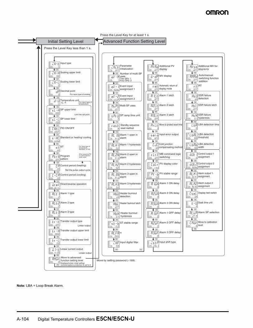
Initial Setting Level Advanced Function Setting Level
in-l0
dp0
in-t5
in-h100
d-uc
s l-h1300
C
s l-l-200
C
cntlonof
s -hcs tnd
s ton
ptr noff
cp20
c-cp20
or eVor -r
alt12
alt22
alt32
tr -toff
tr -h100.0
tr -l0.0
o1-t4-20
amoV0
Input type
Scaling upper limit
Scaling lower limit
Decimal point
Temperature unit
SP upper limit
SP lower limit
PID ON/OFF
Standard or heating/ cooling
ST
Program pattern
Control period (heating)
Control period (cooling)
Direct/reverse operation
Alarm 1 type
Alarm 2 type
Alarm 3 type
Transfer output type
Transfer output upper limit
Transfer output lower limit
Linear current output
initoff
eV-m1
eV-1none
eV-2s top
ms puoff
s pr um
r es ta
al1nn-o
alh10.2
C
al2nn-o
alh20.2
C
al3nn-o
alh30.2
C
hbuon
hbloff
hbh0.1
s t-b15.0
C
alfa0.65
inf0.0
pVadoff
o-dpoff
r etoff
a1ltoff
a2ltoff
a3ltoff
pr lt3
s er ooff
cjcon
r lr Voff
colrr ed
pV-b5.0
C
a1on0
a2on0
a3on0
a1of0
a2of0
a3of0
is tpins 1
mVs eoff
amadoff
r toff
hs uon
hs loff
hs h0.1
lba0
lbal8.0
C
lbab3.0
C
out1o
out2none
alm1alm1
alm2alm2
cs elon
t-um
als ps p-m
cmoV0
Parameter initialization
Number of multi-SP uses
Event input assignment 1
Event input assignment 2
Multi-SP uses
SP ramp time unit
Alarm 1 open in alarm
Alarm 1 hysteresis
Alarm 2 open in alarm
Alarm 2 hysteresis
Alarm 3 open in alarm
Alarm 3 hysteresis
Heater burnout detection
Heater burnout latch
ST stable range
α
Input digital filter
Additional PV display
MV display
Automatic return of display mode
Alarm 1 latch
Alarm 2 latch
Alarm 3 latch
Move to protect level time
Input error output
Cold junction compensating method
MB command logic switching
PV display color
PV stable range
Alarm 1 ON delay
Alarm 2 ON delay
Alarm 3 ON delay
Alarm 1 OFF delay
Alarm 2 OFF delay
Alarm 3 OFF delay
Input shift type
Additional MV for stop/error
RT
SSR failure detection
SSR failure latch
SSR failure hysteresis
LBA detection time
LBA detection threshold
LBA detection width
Control output 1 assignment
Control output 2 assignment
Alarm output 1 assignment
Alarm output 2 assignment
Display text switch
Soak time unit
Alarm SP selection
Move to calibration level
Press the Level Key less than 1 s.
Move by setting password (−169).
Press the Level Key for at least 1 s.
Two SPs: 1 Four SPs: 2
For input type of analog
Limit the set point.
Set the pulse output cycle.
Linear output
Linear output
°C, °F
a
For input type of temperature
For input type of temperature, standard, or PID
When assigning PID or control output to pulse output
Displayed when initial setting/ communications protection is set to 0
Move to advanced function setting level
Heater burnout hysteresis
Standby sequence reset method
Auto/manual switching function addition
a
a
a
a
a
a
a
a
a
a
a
a
a
a
a
a
a
a
a
a
a
a
a
a
a
a
a
a
a
a
a
a
a
a
a
a
a
a
a
a
a
a
a
a
a
a
a
a
a
a
a
a
a
a
a
a
a
a
a
a
a
a
a
a
a
a
a
a
a
a
a
a
a
a
a
a
%&
,, &-&"! "!"
-&) &- C & - " ! "!"'!!E&− /B°*
C #-("& - ! " !" .""
C - "& ) " ! + ! F<
C ! "+ : &"! 9>
/ 2 8-(7
C#"
C# !
C@ I
C@
C# "
#%&- "&!!&+!5,.5(!!
7"/ " & / I/ ! - &"!&/!(4() )N,'(8 9*( ")N,'(8 B*
',
(' ! "*(#' ! " *
*',
(',& " " *
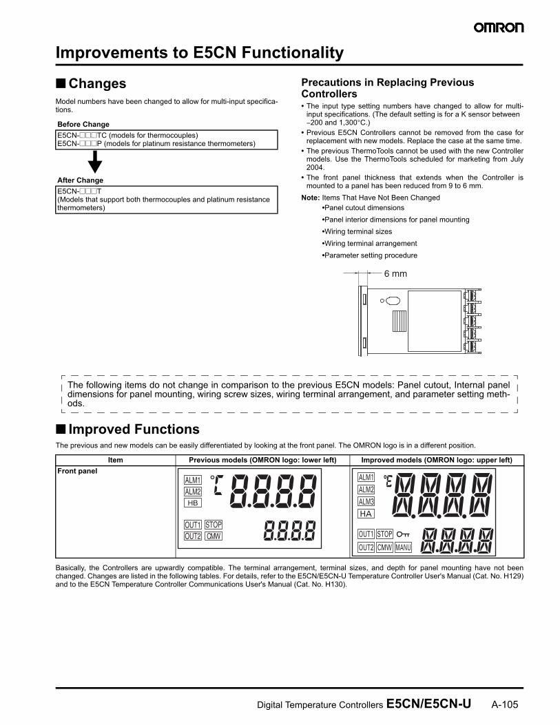
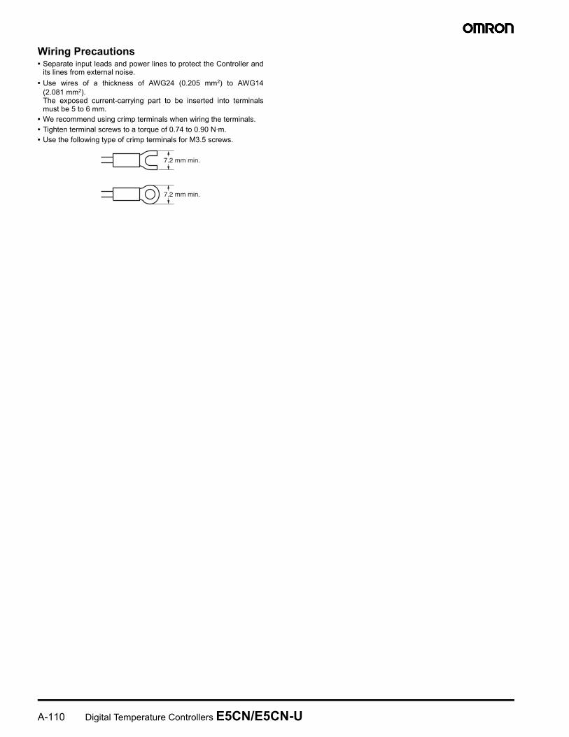
6 mm
-# 326)2 / '4 ## 326)2 / '4
%
! "" -( 0#"/2 ! /"I/ /
ALM1ALM2HB
OUT1OUT2
STOPCMW
>
!&'&
)
-# ##
-&
?$' <$/4>8I*<$4B@'<$/4>8I<$*
?$' <$/4>8I*<$4B@'<$/4>8I<$*
>$' <$/4>8I*B$4@'<$/4>8I<$*
>$' <$/4>8I*B$4@'<$/4>8I<$*
! (
"0E/F///1/)/(/./%/7
2! 0 ?°/> ° >°' >>°*$0 $
(', *
"0E/F///1/)/(/./%/7
2! 0 ?°/> ° >°' >>°*$0 $
# " 0# F# (#
# " 0# F#
'( * (1',*
0<
$0 $/$/ $
) (.
%#%(5/$/B'-*
""!0 /
(.
%#%(5/$/B'-*
""!0 /
(;' !*'&-&*
%#%(5/$/B'-*
""!0 // "&""
+ (6
$± D'#(#*
,:"0
@"""
(6
$± D'#(#*
,:"0
@"""
(
<
10>Ω :
.0:/>
(
<
10>Ω :
.0:/?
0
+ '( "* '5)*
$± D'#(#*
,:"0
@"""
,# ? 1"
"0#$099 /%$0><
1"'2 --&*'? &*"0#$0 /%$0>
' '( !* ('"*
""
<
10>Ω :
.0:/?
?
2,%&
,&&
&!&'&
5!!)% &,&&
-# ##
# +!"'-!*
#$"&"'4* #$"&B"'44*
"""'? 4 *
!' !! /!!""*
!'!&! *
2 ,
,$
,$#$
1&+
0 99 0 99
.&
*
%#"'"! !%#"*
2, % !"
# -"-
%!
-# ##
! #
-# ##
&&
@4'%;%@;* @4'%;%@;*/,&
# /</</9>/ 9& /</</9>/ 9/B<&
-# ##
6E,& 5)%$
5)%
5)'*
!!)' #& %%.!"
-&
/ %1$""! &!"/:"B$ <<$+>$
0 ""!&)1-"-!"""!"-
-&'!' !"
C 1":! -"
C 1"&M":
C 1"&M""
C 1"&M""-'"! *
C 1"&M"- "
C 1"&M"""
C 1"&M"-&"+
0 ) & @ I""-": / "& -"!"2""/!""&! !- "
7 " &"+ -
8 7 ""
)" "! ',B/? :*) ! "+ ! @C< ' * @C <' * : "" & &>
""
B " " & & -"!!3"'!3"/!3" "/"*E ! N &"+ ! "& " - "/
? ) - "!"
> %-"-"!5(
1 B !
@!/5(!'/* &!
0 2 " "" &+ & """&5 "&
7 2! -! "/""+""@"&"+"/ +""" """
8 )"" -&&"
2 3 " ! ! &I!5( '/"*!
55 " ! !&!"
"! & "" """+
"! " "" """+/!/ 3
"&M"! &:- "" M:
&/ !/ "" "" """+/!/ 3
0!""%"+
* )1"")""!-
&* @ "!!"/5" &! ""
"* %%1$"""'% *
* 0"!!"""+/""!!!"""'%*
2!&!:""/"" ""&" !&""""&""!:""!:""!-"&""""""
""""! "&" "3&?<9(P
,+! &!" :""" 3 M
@0""""+!/ "- -!!
+! /" /!-! !"! 1!" !" """ " 3
!CAUTION
9
-&'&
!&.'
) ! 0
0− °'""*8 0DD
2!"&/ & &+°/"
0 -"!!""-"+ & & ! "&&-"!!""" -"!!!"& & 0 /-"!/ /-"!!/-" !"&:& !
7 @ I""-":/ " & -"!"2""/!""&! !- " @ -!""/-/&"!" "-
6*&&&
@ : "" " / & " " "
0 @:""! " /&-"+"!
7 , I-
8 2! """/""+!!&""
('
! " &%" "!"!"2#!
0(,<J!'3-2#>>*."02#/ "02#'()003-2#/"02#/ 02#*
2-&
2 + : " ! 5(! !5(" &- " 3"""
0 @!/5(!'/* &! 2! 5( ! &!5(!/!&! "&"-
7 @ ! /55( 5(!'2! 5 5( / " ! %5# .)( "&*
8 -"/-/-"""&""-!!"! "!
6
6-
!/!"+C ! ! "+ 3 ! !"#, " ()@!"+"()
0 2(4()
7 #&! /!
8 !:" " + &" 3!9B9(P
*&,,
,+G)#H( "-& !
), ',
@" "/"& -! " ""& -! "(2"& -()
2'& *+
0 2&!" !8&! ! "!"
7 7!/"! &&"2 """+#+& !"& +" "+ "7""" """
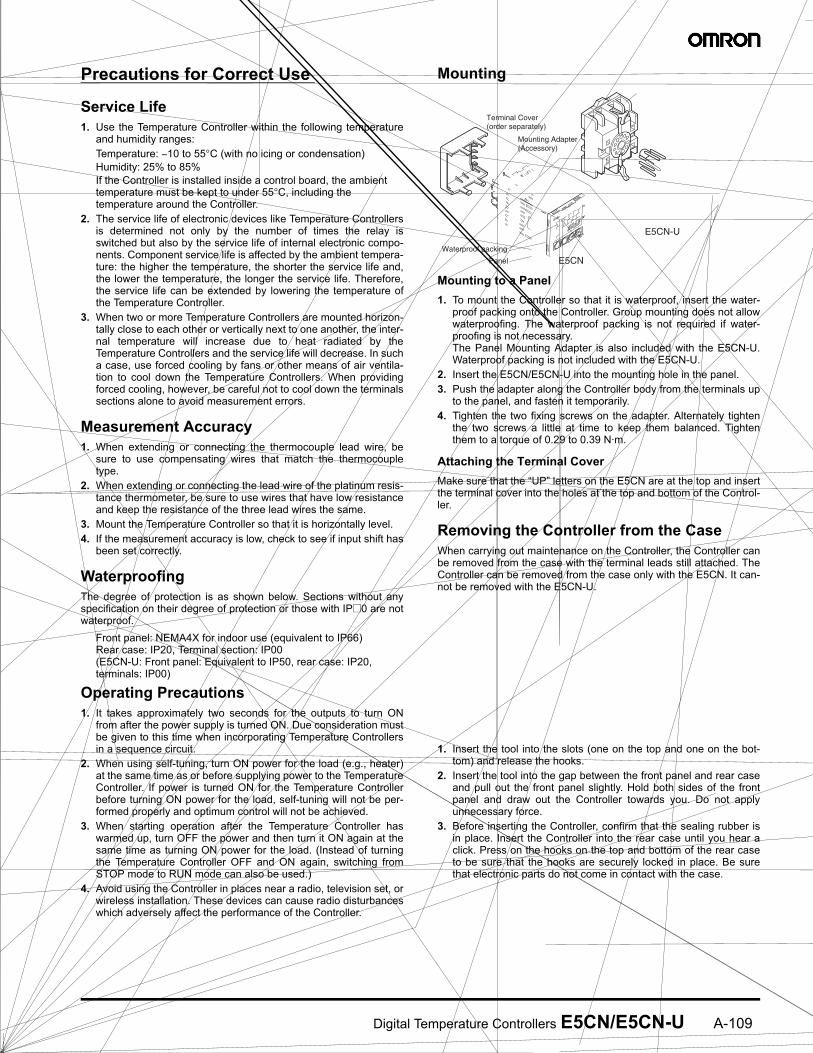
Terminal Cover (order separately)
Mounting Adapter (Accessory)
E5CN
E5CN-U
Waterproof packing
Panel
Order the P2CF-113or P3GA-113
Socket separately.Front-mounting Socket
(Panel mounting is also possible.)
E5CN
PV
SV
ALM1 ALM2 ALM3 HAOUT1 STOP OUT2 CMW MANU
(1)(1)(2)(3)
Tool insertion hole
Flat-blade screwdriver(Unit: mm)
(-&C %"! :
C ) ! "+ ! @C< ' * @C <
' * : "" & &>
C @" "
C "3!?<9(P
C )!!" !,B"
7.2 mm min.
7.2 mm min.

! ! "! # # ! $ %& ''(% %%) * + !! #
! %) % *
, - ( ! ! # * ! . !% # + *
/ 011 %2 $# # * % % ! %
## !%# # 3 " $
4 . . ! # . ! ! 3 % % !! ! # !! $ ! . ! ! # . % %*
5 67 * % ! # 3 # 7* 8 ! % $ $* !"% ! ! %* * # %
9 ( & %) * .
: 6 ;) % % # % ! 38 ! !!8 % ! % ! ! % ! ! 8 3 #
1 - # < . % = % % % % * #
# * $% 6* "
% ! 8 $ * !# $ %*
- # 8 $
. ( % *
$% # % ,1 "% % # $
> &.# > + .# $% 8 # % . % ! . % '&''&?;@&A>??AB??&?&&A7A!&C?&? 7;'7&-!*<AA"7A6?7A$&;&A!;&?(DA*7'"7B ? 67A& 6? ?7(<'? <?& 6 D& $-*<B&?(@A>'&-$&D7'A&D-&&?;7A&-DD&$- >7'' <7*'B ;&& D& ?&E<7?&;&A 6 D&7?7A&A-&-<& % . % % $ " * ? + %" % * % % # "$! + ! * 3 $# # % % ! ! . $ + $ ! ! %) "!% ! ? %* % # % % % % %% $% !! % % # # ! # ! % %#
, - '&&''&?D''A*&'7*'&6?&(7'!7A-7"?&( ? (A&E<&A7' -;$&! ' 6 ?67 ? ?"-<(7A?(;;&?(7''7AAB>B(AA&(&->7DD&$-!>D&D&?<(D('7;7*&-7A(A?(!>??AB!A&$'7$&A(&??7('7*7'7B 6 ! # % . # $%
/ 7 * ! % ! ! ! . + . !# "! * + $> !* . % . % $ *
2 ( % $ .# * A" * ! .# % * $ " ! * % #
4; ># A % . % * # % % * + % * $!"#% # % # %7# # #!## # * # # !
%< % % "! % $ * + $* + 3 ! # % $% % $ % ! ! ! . % # % .# % $! % % $= ! ##
! % & !% ! !#
! 3 ! !# ! 3 !%) #
! 3 8 8% # % % $
A&F&?<&D&?-<(6?A'7(7A7AF'F7A$&?7<?7@'76&??&?B>7D<&A<?7A$DD&B&;>D'&D*&&A-&7$A&---?&D&?7@!A-DD& &''&?+ ?-<( 7 ?&?'B ?&- A- 7A''&- 6?D&7A&A-&-<&>7D7AD&F&?''&E<7;&A?B&;
% % % + "% $! 3
, - # # % 7 + ! " 3 %) +>''%
/ ( % % # 7" % % ! D # ! " $% > %! % % . %8 + # $
2 & % 8 % # % # ! % ! !
$%"=GG<"=GGG ("=GG
Cat. No. H301-E3-1 6/04 Specifications subject to change without notice Printed in USA
! "#992; # !;*2F9
$%&'&&$&(
( -# %!7'415,
$)$*)+,,6< 3 =
,,((&&)&&
- ./ 012
111# # 3H/- 2.2"/4#
!56 ## !%11,:,5# !%11,25