Embed Size (px)
Citation preview
600 A 15/25 kV class BOL-T™ and separable splice connector assembly installation instructions
COOPER POWERSERIES
Deadbreak Apparatus Connectors MN650005EN
Effective February 2015Supersedes S600-10-2 July 2014
DISCLAIMER OF WARRANTIES AND LIMITATION OF LIABILITY
The information, recommendations, descriptions and safety notations in this document are based on Eaton Corporation’s (“Eaton”) experience and judgment and may not cover all contingencies. If further information is required, an Eaton sales office should be consulted. Sale of the product shown in this literature is subject to the terms and conditions outlined in appropriate Eaton selling policies or other contractual agreement between Eaton and the purchaser.
THERE ARE NO UNDERSTANDINGS, AGREEMENTS, WARRANTIES, EXPRESSED OR IMPLIED, INCLUDING WARRANTIES OF FITNESS FOR A PARTICULAR PURPOSE OR MERCHANTABILITY, OTHER THAN THOSE SPECIFICALLY SET OUT IN ANY EXISTING CONTRACT BETWEEN THE PARTIES. ANY SUCH CONTRACT STATES THE ENTIRE OBLIGATION OF EATON. THE CONTENTS OF THIS DOCUMENT SHALL NOT BECOME PART OF OR MODIFY ANY CONTRACT BETWEEN THE PARTIES.
In no event will Eaton be responsible to the purchaser or user in contract, in tort (including negligence), strict liability or other-wise for any special, indirect, incidental or consequential damage or loss whatsoever, including but not limited to damage or loss of use of equipment, plant or power system, cost of capital, loss of power, additional expenses in the use of existing power facilities, or claims against the purchaser or user by its customers resulting from the use of the information, recom-mendations and descriptions contained herein. The information contained in this manual is subject to change without notice.
ii 600 A 15/25 kV class BOL-T connector assembly installation instructions MN650005EN February 2015
Contents
SAFETY INFORMATIONSafety Information . . . . . . . . . . . . . . . . . . . . . . . . . . . . . . . . . . . . . . . . . . . . . . . . . . . . . . . . . . . . . . . . . . . . . . . . . . . . . iv
PRODUCT INFORMATIONIntroduction . . . . . . . . . . . . . . . . . . . . . . . . . . . . . . . . . . . . . . . . . . . . . . . . . . . . . . . . . . . . . . . . . . . . . . . . . . . . . . . . . . .1
Acceptance and Initial Inspection. . . . . . . . . . . . . . . . . . . . . . . . . . . . . . . . . . . . . . . . . . . . . . . . . . . . . . . . . . . . . . . . . . .1
Handling and Storage . . . . . . . . . . . . . . . . . . . . . . . . . . . . . . . . . . . . . . . . . . . . . . . . . . . . . . . . . . . . . . . . . . . . . . . . . . . .1
Standards . . . . . . . . . . . . . . . . . . . . . . . . . . . . . . . . . . . . . . . . . . . . . . . . . . . . . . . . . . . . . . . . . . . . . . . . . . . . . . . . . . . . .1
EQUIPMENT REQUIREDEquipment Required. . . . . . . . . . . . . . . . . . . . . . . . . . . . . . . . . . . . . . . . . . . . . . . . . . . . . . . . . . . . . . . . . . . . . . . . . . . . .2
TOOLS REQUIREDTools Required . . . . . . . . . . . . . . . . . . . . . . . . . . . . . . . . . . . . . . . . . . . . . . . . . . . . . . . . . . . . . . . . . . . . . . . . . . . . . . . . .2
INSTALLATION OF CONNECTORSShear Bolt Installation Procedure. . . . . . . . . . . . . . . . . . . . . . . . . . . . . . . . . . . . . . . . . . . . . . . . . . . . . . . . . . . . . . . . . . .2
Compression Connector Procedure . . . . . . . . . . . . . . . . . . . . . . . . . . . . . . . . . . . . . . . . . . . . . . . . . . . . . . . . . . . . . . . . .7
COMPLETING T-BODY TERMINATIONInstallation of BOL-T Connector Onto Apparatus Bushing . . . . . . . . . . . . . . . . . . . . . . . . . . . . . . . . . . . . . . . . . . . . . . . 11
Separable Splice Assembly Instructions. . . . . . . . . . . . . . . . . . . . . . . . . . . . . . . . . . . . . . . . . . . . . . . . . . . . . . . . . . . . .14
iii600 A 15/25 kV class BOL-T connector assembly installation instructions MN650005EN February 2015
The instructions in this manual are not intended as a substitute for proper training or adequate experience in the safe operation of the equipment described. Only competent technicians who are familiar with this equipment should install, operate, and service it.
A competent technician has these qualifications:
• Is thoroughly familiar with these instructions.
• Is trained in industry-accepted high and low-voltage safe operating practices and procedures.
• Is trained and authorized to energize, de-energize, clear, and ground power distribution equipment.
• Is trained in the care and use of protective equipment such as arc flash clothing, safety glasses, face shield, hard hat, rubber gloves, clampstick, hotstick, etc.
Following is important safety information. For safe installation and operation of this equipment, be sure to read and understand all cautions and warnings.
Safety instructionsFollowing are general caution and warning statements that apply to this equipment. Additional statements, related to specific tasks and procedures, are located throughout the manual.
Safety for life!
SAFETYFOR LIFE
!SAFETYFOR LIFE
Eaton meets or exceeds all applicable industry standards relating to product safety in its Cooper Power™ series products. We actively promote safe practices in the use and maintenance of our products through our service literature, instructional training programs, and the continuous efforts of all Eaton employees involved in product design, manufacture, marketing, and service.
We strongly urge that you always follow all locally approved safety procedures and safety instructions when working around high voltage lines and equipment, and support our “Safety For Life” mission.
Safety information
DANGERHazardous voltage. Contact with hazardous voltage will cause death or severe personal injury. Follow all locally approved safety procedures when working around high- and low-voltage lines and equipment. G103.3
WARNING Before installing, operating, maintaining, or testing this equipment, carefully read and understand the contents of this manual. Improper operation, handling or maintenance can result in death, severe personal injury, and equipment damage. G101.0
WARNING This equipment is not intended to protect human life. Follow all locally approved procedures and safety practices when installing or operating this equipment. Failure to comply can result in death, severe personal injury and equipment damage. G102.1
WARNING Power distribution and transmission equipment must be properly selected for the intended application. It must be installed and serviced by competent personnel who have been trained and understand proper safety procedures. These instructions are written for such personnel and are not a substitute for adequate training and experience in safety procedures. Failure to properly select, install or maintain power distribution and transmission equipment can result in death, severe personal injury, and equipment damage. G122.3
This manual may contain four types of hazard statements:
DANGER Indicates an imminently hazardous situation which, if not avoided, will result in death or serious injury.
WARNING Indicates a potentially hazardous situation which, if not avoided, could result in death or serious injury.
CAUTION Indicates a potentially hazardous situation which, if not avoided, may result in minor or moderate injury.
CAUTION: Indicates a potentially hazardous situation which, if not avoided, may result in equipment damage only.
Hazard Statement Definitions
iv 600 A 15/25 kV class BOL-T connector assembly installation instructions MN650005EN February 2015
Product information
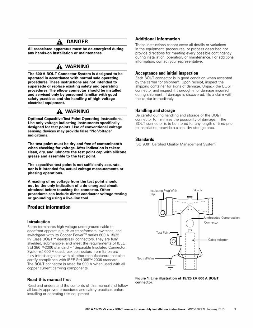
IntroductionEaton terminates high-voltage underground cable to deadfront apparatus such as transformers, switches, and switchgear with its Cooper Power™ series 600 A 15/25 kV Class BOL-T™ deadbreak connectors. They are fully shielded, submersible, and meet the requirements of IEEE Std 386™-2006 standard – “Separable Insulated Connector Systems”. 600 A deadbreak connectors from Eaton are fully interchangeable with all other manufacturers that also certify compliance with IEEE Std 386™-2006 standard. The BOL-T connector is rated for 900 A when used with all copper current carrying components.
Read this manual firstRead and understand the contents of this manual and follow all locally approved procedures and safety practices before installing or operating this equipment.
Additional informationThese instructions cannot cover all details or variations in the equipment, procedures, or process described nor provide directions for meeting every possible contingency during installation, operation, or maintenance. For additional information, contact your representative.
Acceptance and initial inspectionEach BOL-T connector is in good condition when accepted by the carrier for shipment. Upon receipt, inspect the shipping container for signs of damage. Unpack the BOL-T connector and inspect it thoroughly for damage incurred during shipment. If damage is discovered, file a claim with the carrier immediately.
Handling and storageBe careful during handling and storage of the BOL-T connector to minimize the possibility of damage. If the BOL-T connector is to be stored for any length of time prior to installation, provide a clean, dry storage area.
StandardsISO 9001 Certified Quality Management System
DANGERAll associated apparatus must be de-energized during any hands-on installation or maintenance.
WARNING The 600 A BOL-T Connector System is designed to be operated in accordance with normal safe operating procedures. These instructions are not intended to supersede or replace existing safety and operating procedures. The elbow connector should be installed and serviced only by personnel familiar with good safety practices and the handling of high-voltage electrical equipment.
WARNING Optional Capacitive Test Point Operating Instructions: Use only voltage indicating instruments specifically designed for test points. Use of conventional voltage sensing devices may provide false “No Voltage” indications.
The test point must be dry and free of contaminant’s when checking for voltage. After indication is taken: clean, dry, and lubricate the test point cap with silicone grease and assemble to the test point.
The capacitive test point is not sufficiently accurate, nor is it intended for, actual voltage measurements or phasing operations.
A reading of no voltage from the test point should not be the only indication of a de-energized circuit obtained before touching the connector. Other procedures can include direct conductor voltage testing or grounding using a live-line tool.
Figure 1. Line illustration of 15/25 kV 600 A BOL-T connector.
Insulating Plug With Cap
T-body
Unthreaded Com pres sion
Connector
Cable Adapter
Test Point
Neutral Wire
1600 A 15/25 kV class BOL-T connector assembly installation instructions MN650005EN February 2015
ote:N If concentric neutral cable is not being used, follow cable preparation directions in shield adapter kit.
Equipment provided
• BOL-T Connector Assembly Kit includes:
• T-body • Cable Adapter • Insulating Plug with Cap • Shear Bolt Connector • Silicone Lubricant • Instruction Sheet • Threaded Stud
Tools required
• Torque Wrench • 5/16" Hex Wrench for Splice Application • Cable Stripping Tools • 5 mm or 8 mm Allen Wrench
Installation of connectors
Shear bolt installation procedures(For compression connector procedures, see page 7)
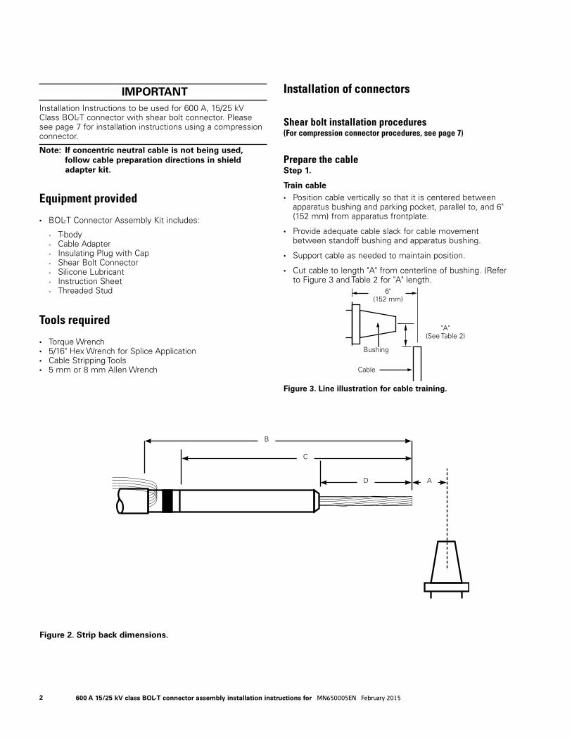
Prepare the cableStep 1.
Train cable • Position cable vertically so that it is centered between
apparatus bushing and parking pocket, parallel to, and 6" (152 mm) from apparatus frontplate.
• Provide adequate cable slack for cable movement between standoff bushing and apparatus bushing.
• Support cable as needed to maintain position.
• Cut cable to length "A" from centerline of bushing. (Refer to Fig ure 3 and Table 2 for "A" length.
IMPORTANT Installation Instructions to be used for 600 A, 15/25 kV Class BOL-T connector with shear bolt connector. Please see page 7 for installation instructions using a compression connector.
Figure 3. Line illustration for cable training.
Bushing
Cable
"A" (See Table 2)
B
C
D A
Figure 2. Strip back dimensions.
6" (152 mm)
2 600 A 15/25 kV class BOL-T connector assembly installation instructions for MN650005EN February 2015
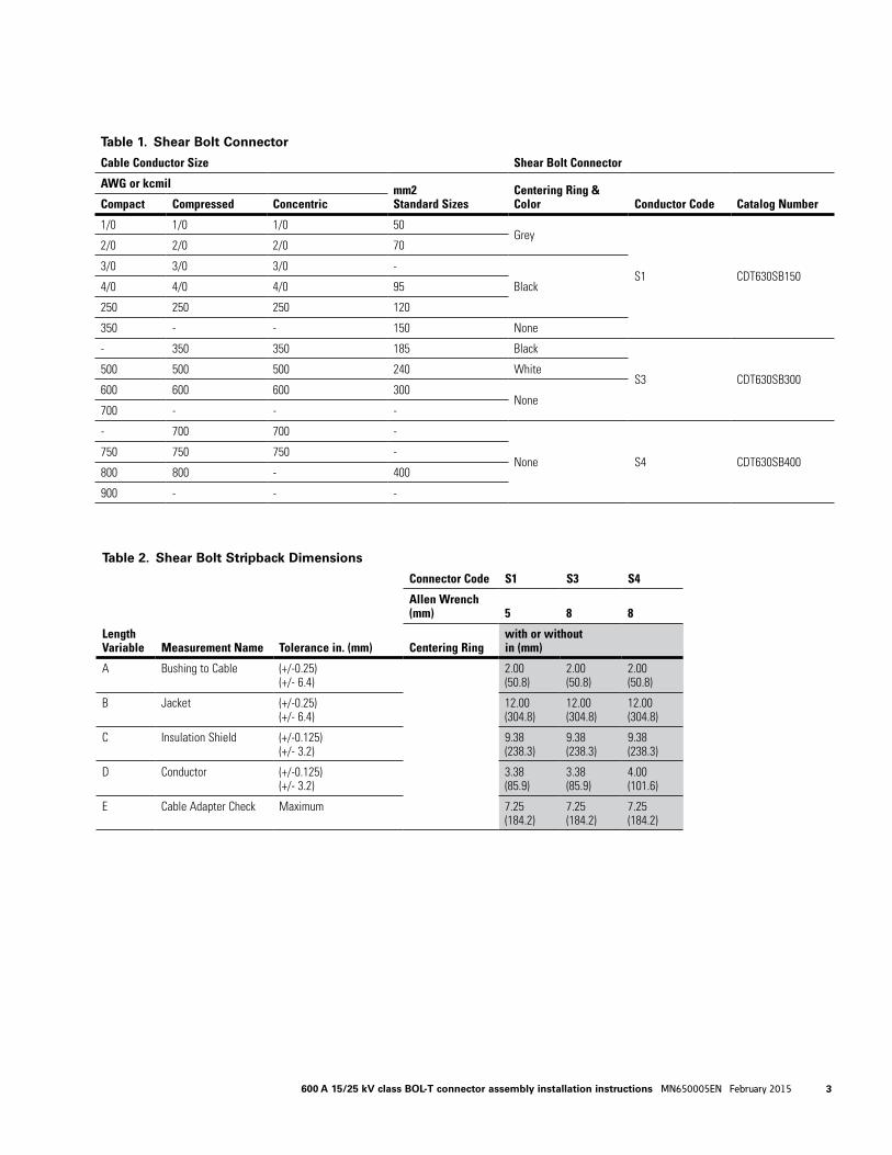
Table 2. Shear Bolt Stripback Dimensions
Length Variable Measurement Name Tolerance in. (mm)
Connector Code S1 S3 S4
Allen Wrench (mm) 5 8 8
Centering Ringwith or withoutin (mm)
A Bushing to Cable (+/-0.25) (+/- 6.4)
2.00 (50.8)
2.00 (50.8)
2.00 (50.8)
B Jacket (+/-0.25) (+/- 6.4)
12.00 (304.8)
12.00 (304.8)
12.00 (304.8)
C Insulation Shield (+/-0.125) (+/- 3.2)
9.38 (238.3)
9.38 (238.3)
9.38 (238.3)
D Conductor (+/-0.125) (+/- 3.2)
3.38 (85.9)
3.38 (85.9)
4.00 (101.6)
E Cable Adapter Check Maximum 7.25 (184.2)
7.25 (184.2)
7.25 (184.2)
Table 1. Shear Bolt Connector
Cable Conductor Size Shear Bolt Connector
AWG or kcmil mm2Standard Sizes
Centering Ring & Color Conductor Code Catalog NumberCompact Compressed Concentric
1/0 1/0 1/0 50Grey
S1 CDT630SB150
2/0 2/0 2/0 70
3/0 3/0 3/0 -
Black4/0 4/0 4/0 95
250 250 250 120
350 - - 150 None
- 350 350 185 Black
S3 CDT630SB300500 500 500 240 White
600 600 600 300None
700 - - -
- 700 700 -
None S4 CDT630SB400750 750 750 -
800 800 - 400
900 - - -
3600 A 15/25 kV class BOL-T connector assembly installation instructions MN650005EN February 2015
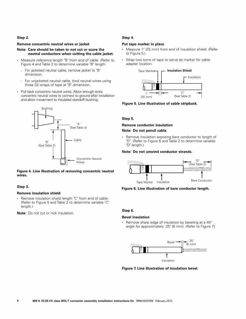
Step 2.
Remove concentric neutral wires or jacket
ote:N Care should be taken to not cut or score the neutral conductors when cutting the cable jacket.
• Measure reference length "B" from end of cable. (Refer to Figure 4 and Table 2 to determine variable "B" length.
• For jacketed neutral cable, remove jacket to "B" dimension.
• For unjacketed neutral cable, bind neutral wires using three (3) wraps of tape at "B" dimension.
• Pull back concentric neutral wires. Allow enough extra concentric neutral wires to connect to ground after installation and allow movement to insulated standoff bushing.
Step 3.
Remove insulation shield • Remove insulation shield length "C" from end of cable.
(Refer to Figure 5 and Table 2 to determine variable "C" length.)
ote:N Do not cut or nick insulation.
Step 4.
Put tape marker in place • Measure 1" (25 mm) from end of insulation shield. (Refer
to Figure 5.)
• Wrap two turns of tape to serve as marker for cable adapter location.
Step 5.
Remove conductor insulation
ote:N Do not pencil cable.
• Remove insulation exposing bare conductor to length of "D". (Refer to Figure 6 and Table 2 to determine variable "D" length.)
ote:N Do not unwind conductor strands.
Step 6.
Bevel insulation • Remove sharp edge of insulation by beveling at a 45°
angle for approximately .25" (6 mm). (Refer to Figure 7.)
Figure 4. Line illustration of removing concentric neutral wires.
Bushing
Cable
"A"(See Table 2)
"B"(See Table 2)
Concentric Neutral Wires
Figure 5. Line illustration of cable stripback.
"C" (See Table 2)
1"(25 mm)
Tape Marker Insulation Shield
Insulation
Figure 6. Line illustration of bare conductor length.
"D" (See Table 2)
Tape Marker Bare ConductorInsulation
Figure 7. Line illustration of insulation bevel.
Bevel
Insulation
.25"(6 mm)
4 600 A 15/25 kV class BOL-T connector assembly installation instructions for MN650005EN February 2015
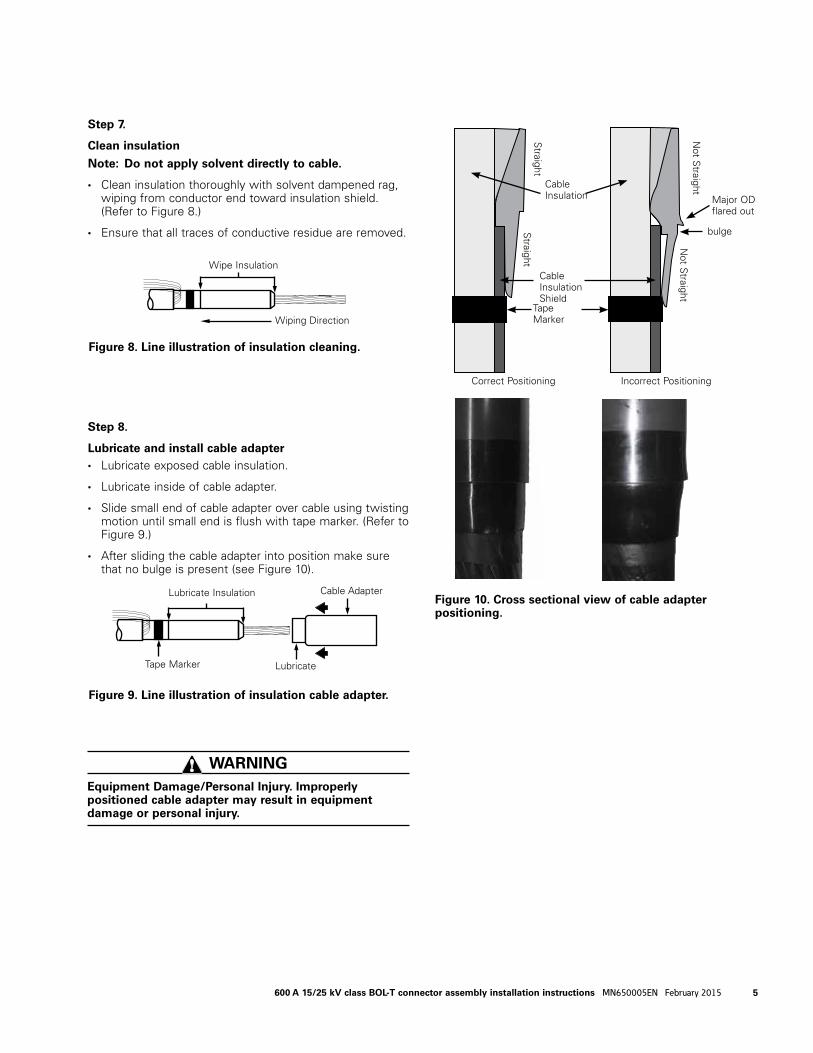
Step 7.
Clean insulation
ote:N Do not apply solvent directly to cable.
• Clean insulation thoroughly with solvent dampened rag, wiping from conductor end toward insulation shield. (Refer to Figure 8.)
• Ensure that all traces of conductive residue are re moved.
Step 8.
Lubricate and install cable adapter • Lubricate exposed cable insulation.
• Lubricate inside of cable adapter.
• Slide small end of cable adapter over cable using twisting motion until small end is flush with tape marker. (Refer to Figure 9.)
• After sliding the cable adapter into position make sure that no bulge is present (see Figure 10).
WARNING Equipment Damage/Personal Injury. Improperly positioned cable adapter may result in equipment damage or personal injury.
Figure 9. Line illustration of insulation cable adapter.
Lubricate Insulation
Lubricate
Cable Adapter
Tape Marker
Figure 8. Line illustration of insulation cleaning.
Wiping Direction
Wipe InsulationS
traightS
traight
Not S
traightN
ot Straight
bulge
Correct Positioning
Cable Insulation
Cable Insulation Shield
Tape Marker
Incorrect Positioning
Major OD flared out
Figure 10. Cross sectional view of cable adapter positioning.
5600 A 15/25 kV class BOL-T connector assembly installation instructions MN650005EN February 2015
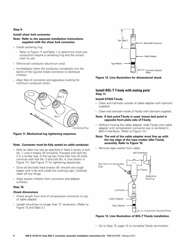
Step 9.
Install shear bolt connector
ote:N Refer to the separate installation instructions supplied with the shear bolt connector.
• Install centering ring.
• Refer to Figure 11 and Table 1 to determine what size conductors require a centering ring and the correct color to use.
• Wire brush conductor (aluminum only).
• Immediately insert the conductor completely into the barrel of the lug and rotate connector to distribute inhibitor.
• Align flats of connector and apparatus bushing for minimum conductor strain.
ote:N Connector must be fully seated on cable conductor.
• With an Allen hex key as specified in Table 2 screw in bolt No. 1 until it breaks off smoothly. Proceed with bolt No. 2 in a similar way. If the lug has more than two (2) bolts, continue with bolt No. 3 and bolt No. 4, (not shown in Figure 11). See Figure 11 for tightening sequences.
• Once all the bolts have broken off, smooth any rough edges with a file and install the covering caps. Carefully clean off any filings.
• Wipe excess inhibitor from connector and adapter surfaces.
Step 10.
Check di men sions • Check length from end of com pres sion con nec tor to top
of cable adapter.
• Length should be no longer than "E" dimension. (Re fer to Fig ure 12 and Table 2.)
Install BOL-T T-body with mating partsStep 11.
Install DT625 T-body • Clean and lubricate outside of cable adapter with lubricant
supplied.
• Clean and lubricate inside of T-body with lubricant supplied.
ote:N If test point T-body is used, insure test point is opposite front plate side of T-body.
• Without moving the cable adapter, slide T-body onto cable adapter until compression connector eye is centered in 600 A interfaces. (Refer to Figure 13.)
ote:N The end of the cable adapter must line up with the top edge of the tape marker after T-body assembly. Refer to Figure 10.
• Remove tape marker from cable.
• Go to Step 12, page 12 to complete T-body termination.
Figure 12. Line illustration for dimensional check.
Shear Bolt Connector
"E"See Table 2
Tape Marker
Cable Adapter
Concentric Neutral Wires
Figure 13. Line illustration of BOL-T T-body installation.
T-body
Cable Adapter
Tape Marker
Concentric Neutral Wires
Lubricate
600 A Interfaces
Apparatus Bushing
Test Point on Accessible Side
Figure 11. Mechanical lug tightening sequence.
Bolt 2
Bolt 1
Bolt 3
Start with Bolt 1Centering Ring
6 600 A 15/25 kV class BOL-T connector assembly installation instructions for MN650005EN February 2015
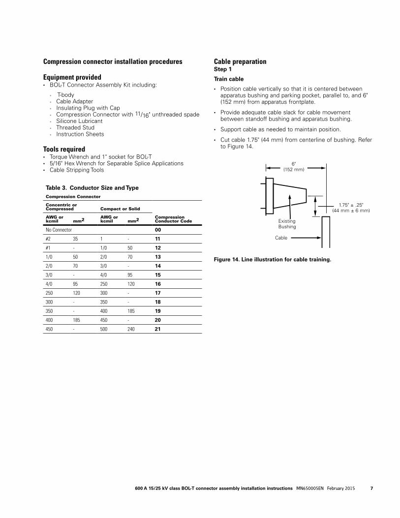
Compression connector installation procedures
Equipment provided • BOL-T Connector Assembly Kit including:
• T-body • Cable Adapter • Insulating Plug with Cap • Compression Connector with 11/16" unthreaded spade • Silicone Lubricant • Threaded Stud • Instruction Sheets
Tools required • Torque Wrench and 1" socket for BOL-T • 5/16" Hex Wrench for Separable Splice Applications • Cable Stripping Tools
Cable preparationStep 1
Train cable
• Position cable vertically so that it is centered between apparatus bushing and parking pocket, parallel to, and 6" (152 mm) from apparatus frontplate.
• Provide adequate cable slack for cable movement between standoff bushing and apparatus bushing.
• Support cable as needed to maintain position.
• Cut cable 1.75" (44 mm) from centerline of bushing. Refer to Figure 14.
Figure 14. Line illustration for cable training.
Existing Bushing
Cable
1.75" ± .25" (44 mm ± 6 mm)
6" (152 mm)
Table 3. Conductor Size and TypeCompression Connector
Concentric or Compressed Compact or Solid
Compression Conductor Code
AWG or kcmil mm2 AWG or
kcmil mm2
No Connector 00
#2 35 1 - 11
#1 - 1/0 50 12
1/0 50 2/0 70 13
2/0 70 3/0 - 14
3/0 - 4/0 95 15
4/0 95 250 120 16
250 120 300 - 17
300 - 350 - 18
350 - 400 185 19
400 185 450 - 20
450 - 500 240 21
7600 A 15/25 kV class BOL-T connector assembly installation instructions MN650005EN February 2015
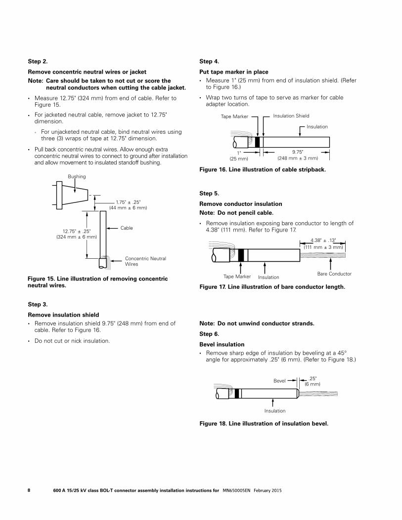
Step 2.
Remove concentric neutral wires or jacket
ote:N Care should be taken to not cut or score the neutral conductors when cutting the cable jacket.
• Measure 12.75" (324 mm) from end of cable. Refer to Figure 15.
• For jacketed neutral cable, remove jacket to 12.75" dimension.
• For unjacketed neutral cable, bind neutral wires using three (3) wraps of tape at 12.75" dimension.
• Pull back concentric neutral wires. Allow enough extra concentric neutral wires to connect to ground after installation and allow movement to insulated standoff bushing.
Step 3.
Remove insulation shield • Remove insulation shield 9.75" (248 mm) from end of
cable. Refer to Figure 16.
• Do not cut or nick insulation.
Step 4.
Put tape marker in place • Measure 1" (25 mm) from end of insulation shield. (Refer
to Figure 16.)
• Wrap two turns of tape to serve as marker for cable adapter location.
Step 5.
Remove conductor insulation
ote:N Do not pencil cable.
• Remove insulation exposing bare conductor to length of 4.38" (111 mm). Refer to Figure 17.
ote:N Do not unwind conductor strands.
Step 6.
Bevel insulation • Remove sharp edge of insulation by beveling at a 45°
angle for approximately .25" (6 mm). (Refer to Figure 18.)
Figure 17. Line illustration of bare conductor length.
4.38" ± .13"(111 mm ± 3 mm)
Tape Marker Bare ConductorInsulation
Figure 18. Line illustration of insulation bevel.
Bevel
Insulation
.25"(6 mm)
Figure 15. Line illustration of removing concentric neutral wires.
Bushing
Cable
1.75" ± .25"(44 mm ± 6 mm)
12.75" ± .25"(324 mm ± 6 mm)
Concentric Neutral Wires
Figure 16. Line illustration of cable stripback.
9.75"(248 mm ± 3 mm)
1"(25 mm)
Tape Marker Insulation Shield
Insulation
8 600 A 15/25 kV class BOL-T connector assembly installation instructions for MN650005EN February 2015

Step 7.
Clean insulation
ote:N Do not apply solvent directly to cable.
• Clean insulation thoroughly with solvent dampened rag, wiping from conductor end toward insulation shield. (Refer to Figure 19.)
• Ensure that all traces of conductive residue are re moved.
Step 8.
Lubricate and install cable adapter • Lubricate exposed cable insulation.
• Lubricate inside of cable adapter.
• Slide small end of cable adapter over cable using twisting motion until small end is flush with tape marker. (Refer to Figure 20.)
• After sliding the cable adapter into position make sure that no bulge is present (see Figure 21).
Figure 19. Line illustration of insulation cleaning.
Wiping Direction
Wipe Insulation
Figure 20. Line illustration of insulation cable adapter.
Lubricate Insulation
Lubricate
Cable Adapter
Tape Marker
Straight
Straight
Not S
traightN
ot Straight
bulge
Correct Positioning
Cable Insulation
Cable Insulation Shield
Tape Marker
Incorrect Positioning
Major OD flared out
Figure 21. Cross sectional view of cable adapter positioning.
WARNING Equipment Damage/Personal Injury. Improperly positioned cable adapter may result in equipment damage or personal injury.
9600 A 15/25 kV class BOL-T connector assembly installation instructions MN650005EN February 2015
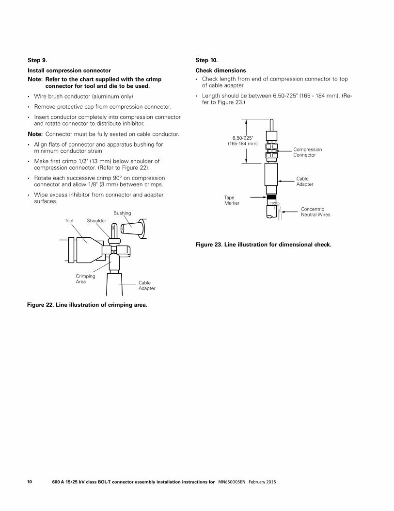
Step 9.
Install compression connector
ote:N Refer to the chart supplied with the crimp connector for tool and die to be used.
• Wire brush conductor (aluminum only).
• Remove protective cap from compression connector.
• Insert conductor completely into compression connector and rotate connector to distribute inhibitor.
ote:N Connector must be fully seated on cable conductor.
• Align flats of connector and apparatus bushing for minimum conductor strain.
• Make first crimp 1/2" (13 mm) below shoulder of compression connector. (Refer to Figure 22).
• Rotate each successive crimp 90° on compression connector and allow 1/8" (3 mm) between crimps.
• Wipe excess inhibitor from connector and adapter surfaces.
Step 10.
Check di men sions • Check length from end of com pres sion con nec tor to top
of cable adapter.
• Length should be be tween 6.50-7.25" (165 - 184 mm). (Re-fer to Fig ure 23.)
Figure 23. Line illustration for dimensional check.
6.50-7.25"(165-184 mm)
Cable Adapter
Concentric Neutral Wires
Tape Marker
Compression Connector
Figure 22. Line illustration of crimping area.
Bushing
ShoulderTool
Crimping Area Cable
Adapter
10 600 A 15/25 kV class BOL-T connector assembly installation instructions for MN650005EN February 2015
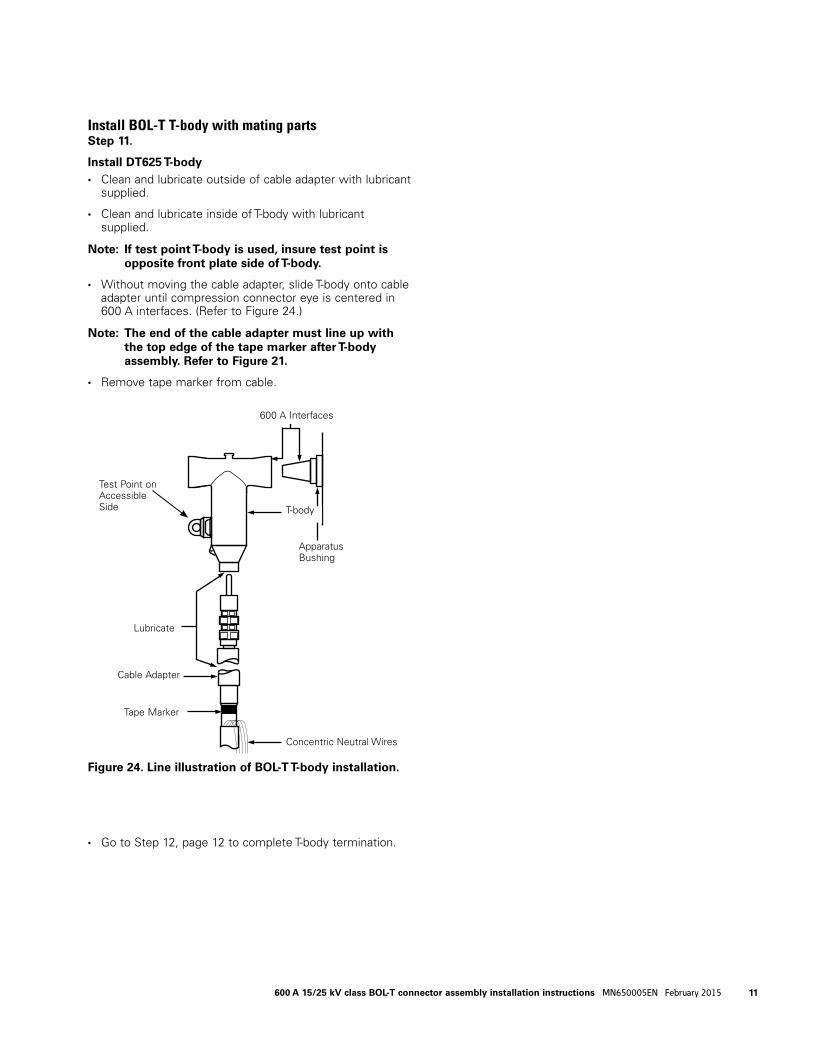
Install BOL-T T-body with mating partsStep 11.
Install DT625 T-body • Clean and lubricate outside of cable adapter with lubricant
supplied.
• Clean and lubricate inside of T-body with lubricant supplied.
ote:N If test point T-body is used, insure test point is opposite front plate side of T-body.
• Without moving the cable adapter, slide T-body onto cable adapter until compression connector eye is centered in 600 A interfaces. (Refer to Figure 24.)
ote:N The end of the cable adapter must line up with the top edge of the tape marker after T-body assembly. Refer to Figure 21.
• Remove tape marker from cable.
• Go to Step 12, page 12 to complete T-body termination.
Figure 24. Line illustration of BOL-T T-body installation.
T-body
Cable Adapter
Tape Marker
Concentric Neutral Wires
Lubricate
600 A Interfaces
Apparatus Bushing
Test Point on Accessible Side
11600 A 15/25 kV class BOL-T connector assembly installation instructions MN650005EN February 2015
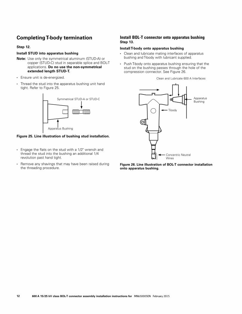
Completing T-body termination
Step 12.
Install STUD into apparatus bushing
ote:N Use only the symmetrical aluminum (STUD-A) or copper (STUD-C) stud in separable splice and BOL-T applications. Do no use the non-symmetrical extended length STUD-T.
• Ensure unit is de-energized.
• Thread the stud into the apparatus bushing unit hand tight. Refer to Figure 25.
• Engage the flats on the stud with a 1/2" wrench and thread the stud into the bushing an additional 1/4 revolution past hand tight.
• Remove any shavings that may have been raised during the threading procedure.
Install BOL-T connector onto apparatus bushingStep 13.
Install T-body onto apparatus bushing • Clean and lubricate mating interfaces of apparatus
bushing and T-body with lubricant supplied.
• Push T-body onto apparatus bushing ensuring that the stud on the bushing passes through the hole of the compression connector. See Figure 26.
1/2" CROWSFOOT WRENCH
Figure 25. Line illustration of bushing stud installation.
Symmetrical STUD-A or STUD-C
Apparatus Bushing
Figure 26. Line illustration of BOL-T connector installation onto apparatus bushing.
Clean and Lubricate 600 A Interfaces
T-body
Apparatus Bushing
Concentric Neutral Wires
12 600 A 15/25 kV class BOL-T connector assembly installation instructions for MN650005EN February 2015
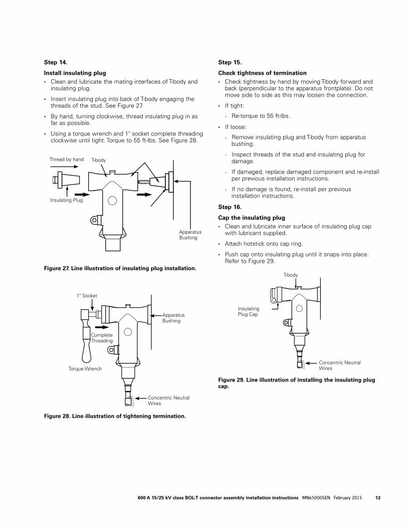
Figure 28. Line illustration of tightening termination.
Apparatus Bushing
1" Socket
Torque Wrench
Complete Threading
Concentric Neutral Wires
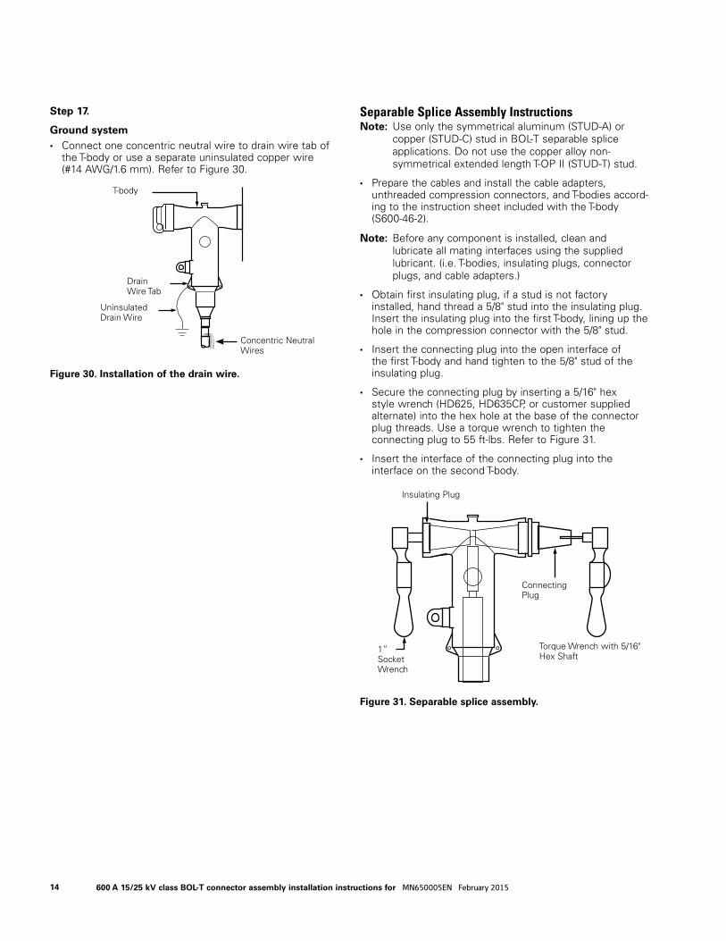
Figure 29. Line illustration of installing the insulating plug cap.
T-body
Insulating Plug Cap
Concentric Neutral Wires
Step 14.
Install insulating plug • Clean and lubricate the mating interfaces of T-body and
insulating plug.
• Insert insulating plug into back of T-body engaging the threads of the stud. See Figure 27.
• By hand, turning clockwise, thread insulating plug in as far as possible.
• Using a torque wrench and 1" socket complete threading clockwise until tight. Torque to 55 ft-lbs. See Figure 28.
Step 15.
Check tightness of termination • Check tightness by hand by moving T-body forward and
back (perpendicular to the apparatus frontplate). Do not move side to side as this may loosen the connection.
• If tight:
• Re-torque to 55 ft-lbs.
• If loose:
• Remove insulating plug and T-body from apparatus bushing.
• Inspect threads of the stud and insulating plug for damage.
• If damaged, replace damaged component and re-install per previous installation instructions.
• If no damage is found, re-install per previous installation instructions.
Step 16.
Cap the insulating plug • Clean and lubricate inner surface of insulating plug cap
with lubricant supplied.
• Attach hotstick onto cap ring.
• Push cap onto insulating plug until it snaps into place. Refer to Figure 29.
Figure 27. Line illustration of insulating plug installation.
T-body
Apparatus Bushing
Insulating Plug
Thread by hand
13600 A 15/25 kV class BOL-T connector assembly installation instructions MN650005EN February 2015
Step 17.
Ground system • Connect one concentric neutral wire to drain wire tab of
the T-body or use a separate uninsulated copper wire (#14 AWG/1.6 mm). Refer to Figure 30.
Separable Splice Assembly Instructionsote:N Use only the symmetrical aluminum (STUD-A) or
copper (STUD-C) stud in BOL-T separable splice applications. Do not use the copper alloy non-symmetrical extended length T-OP II (STUD-T) stud.
• Prepare the cables and install the cable adapters, unthreaded compression connectors, and T-bodies accord-ing to the instruction sheet included with the T-body (S600-46-2).
ote:N Before any component is installed, clean and lubricate all mating interfaces using the supplied lubricant. (i.e. T-bodies, insulating plugs, connector plugs, and cable adapters.)
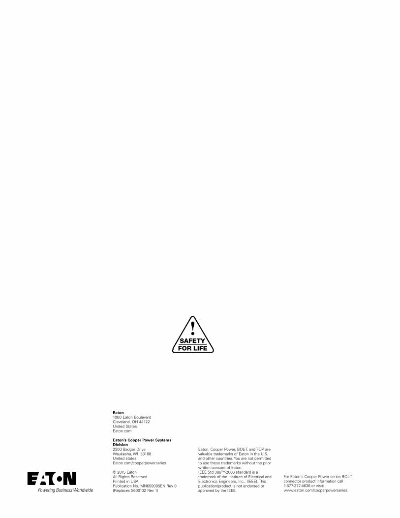
• Obtain first insulating plug, if a stud is not factory installed, hand thread a 5/8" stud into the insulating plug. Insert the insulating plug into the first T-body, lining up the hole in the compression connector with the 5/8" stud.
• Insert the connecting plug into the open interface of the first T-body and hand tighten to the 5/8" stud of the insulating plug.
• Secure the connecting plug by inserting a 5/16" hex style wrench (HD625, HD635CP, or customer supplied alternate) into the hex hole at the base of the connector plug threads. Use a torque wrench to tighten the connecting plug to 55 ft-lbs. Refer to Figure 31.
• Insert the interface of the connecting plug into the interface on the second T-body.
Figure 30. Installation of the drain wire.
Uninsulated Drain Wire
Drain Wire Tab
T-body
Concentric Neutral Wires
Figure 31. Separable splice assembly.
Connecting Plug
1” Socket Wrench
Insulating Plug
Torque Wrench with 5/16" Hex Shaft
14 600 A 15/25 kV class BOL-T connector assembly installation instructions for MN650005EN February 2015
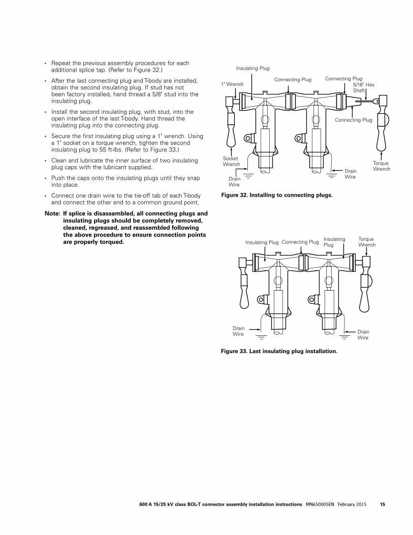
Figure 32. Installing to connecting plugs.
In su lat ing Plug
Connecting PlugConnecting Plug
Connecting Plug
Drain Wire
Drain Wire
5/16" Hex Shaft
1" Wrench
Torque Wrench
Socket Wrench
Figure 33. Last insulating plug installation.
In su lat ing PlugInsulating Plug
Torque WrenchConnecting Plug
Drain Wire Drain
Wire
• Repeat the previous assembly procedures for each additional splice tap. (Refer to Figure 32.)
• After the last connecting plug and T-body are installed, obtain the second insulating plug. If stud has not been factory installed, hand thread a 5/8" stud into the insulating plug.
• Install the second insulating plug, with stud, into the open interface of the last T-body. Hand thread the insulating plug into the connecting plug.
• Secure the first insulating plug using a 1" wrench. Using a 1" socket on a torque wrench, tighten the second insulating plug to 55 ft-lbs. (Refer to Figure 33.)
• Clean and lubricate the inner surface of two insulating plug caps with the lubricant supplied.
• Push the caps onto the insulating plugs until they snap into place.
• Connect one drain wire to the tie-off tab of each T-body and connect the other end to a common ground point.
ote:N If splice is disassembled, all connecting plugs and insulating plugs should be completely removed, cleaned, regreased, and reassembled following the above procedure to ensure connection points are properly torqued.
15600 A 15/25 kV class BOL-T connector assembly installation instructions MN650005EN February 2015
!SAFETYFOR LIFE
Eaton, Cooper Power, BOL-T, and T-OP are valuable trademarks of Eaton in the U.S. and other countries. You are not permitted to use these trademarks without the prior written consent of Eaton. IEEE Std 386™-2006 standard is a trademark of the Institute of Electrical and Electronics Engineers, Inc., (IEEE). This publication/product is not endorsed or approved by the IEEE.
Eaton1000 Eaton BoulevardCleveland, OH 44122United StatesEaton.com
Eaton’s Cooper Power Systems Division2300 Badger DriveWaukesha, WI 53188United statesEaton.com/cooperpowerseries
© 2015 EatonAll Rights ReservedPrinted in USAPublication No. MN650005EN Rev 0(Replaces S600102 Rev 1)
For Eaton's Cooper Power series BOL-T connector product information call 1-877-277-4636 or visit: www.eaton.com/cooperpowerseries.