Embed Size (px)
Citation preview
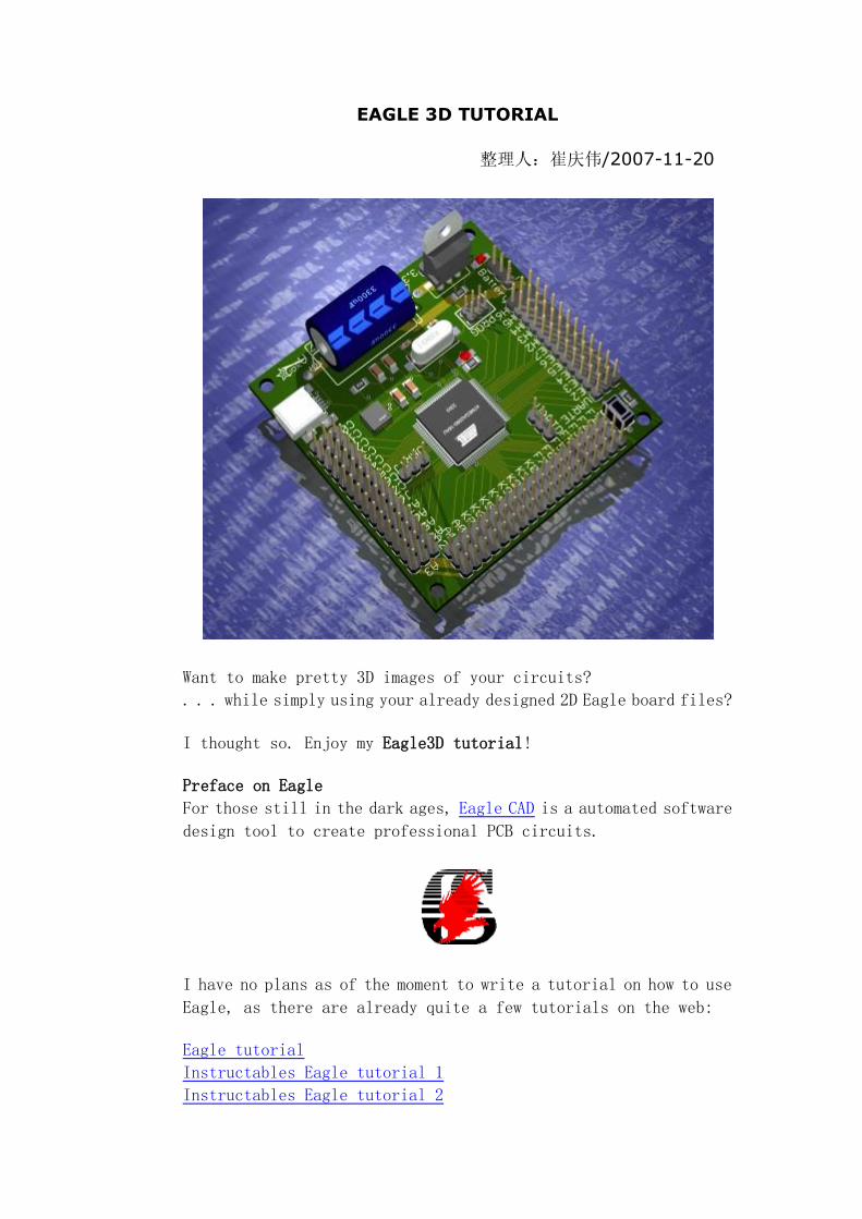
EAGLE 3D TUTORIAL
整理人:崔庆伟/2007-11-20
Want to make pretty 3D images of your circuits?
. . . while simply using your already designed 2D Eagle board files?
I thought so. Enjoy my Eagle3D tutorial!
Preface on Eagle
For those still in the dark ages, Eagle CAD is a automated software
design tool to create professional PCB circuits.
I have no plans as of the moment to write a tutorial on how to use
Eagle, as there are already quite a few tutorials on the web:
Eagle tutorial
Instructables Eagle tutorial 1
Instructables Eagle tutorial 2
University of Florida Eagle tutorial
Sparkfun Eagle tutorial 1
Sparkfun Eagle tutorial 2
Sparkfun Eagle tutorial 3
After you have designed your circuit, you would probably next want
to view the propagated PCB in 3D for both verification and
cool-looking presentations. This is where we will start.
Eagle3D
When I first started using Eagle3D, it quickly became apparent that
the documentation seemed to have forgotten that whole 'how do I use
the software?' bit . . . I wasted several hours trying to figure
it out . . . And I'm sure many others have as well . . .
But thankfully you have this tutorial, so it should only take you
about 10 minutes =)
Step 1
Download the Eagle3D software (1.6mb). Install the software using
the installer. I installed it here:
C:\Program Files\EAGLE-4.16r2\Eagle3D
but it doesn't actually matter where.
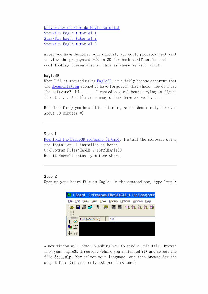
Step 2
Open up your board file in Eagle. In the command bar, type 'run':
A new window will come up asking you to find a .ulp file. Browse
into your Eagle3D directory (where you installed it) and select the
file 3d41.ulp. Now select your language, and then browse for the
output file (it will only ask you this once).
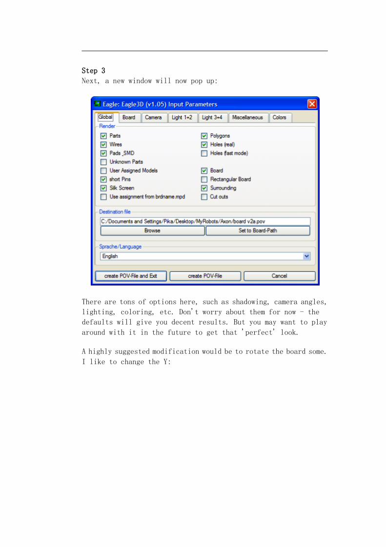
Step 3
Next, a new window will now pop up:
There are tons of options here, such as shadowing, camera angles,
lighting, coloring, etc. Don't worry about them for now - the
defaults will give you decent results. But you may want to play
around with it in the future to get that 'perfect' look.
A highly suggested modification would be to rotate the board some.
I like to change the Y:
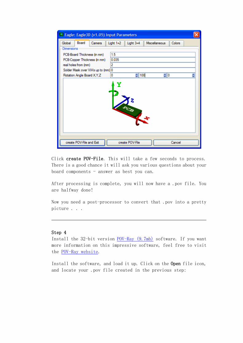
Click create POV-File. This will take a few seconds to process.
There is a good chance it will ask you various questions about your
board components - answer as best you can.
After processing is complete, you will now have a .pov file. You
are halfway done!
Now you need a post-processor to convert that .pov into a pretty
picture . . .
Step 4
Install the 32-bit version POV-Ray (9.7mb) software. If you want
more information on this impressive software, feel free to visit
the POV-Ray website.
Install the software, and load it up. Click on the Open file icon,
and locate your .pov file created in the previous step:
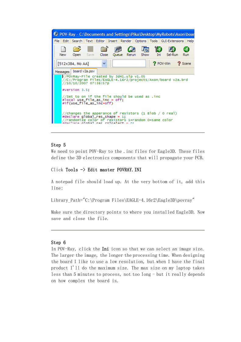
Step 5
We need to point POV-Ray to the .inc files for Eagle3D. These files
define the 3D electronics components that will propagate your PCB.
Click Tools -> Edit master POVRAY.INI
A notepad file should load up. At the very bottom of it, add this
line:
Library_Path="C:\Program Files\EAGLE-4.16r2\Eagle3D\povray"
Make sure the directory points to where you installed Eagle3D. Now
save and close the file.
Step 6
In POV-Ray, click the Ini icon so that we can select an image size.
The larger the image, the longer the processing time. When designing
the board I like to use a low resolution, but when I have the final
product I'll do the maximum size. The max size on my laptop takes
less than 5 minutes to process, not too long - but it really depends
on how complex the board is.
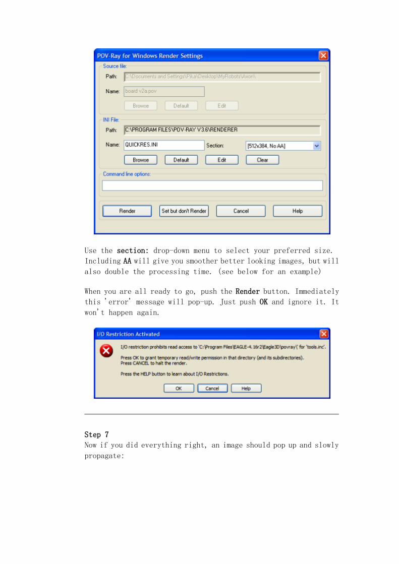
Use the section: drop-down menu to select your preferred size.
Including AA will give you smoother better looking images, but will
also double the processing time. (see below for an example)
When you are all ready to go, push the Render button. Immediately
this 'error' message will pop-up. Just push OK and ignore it. It
won't happen again.
Step 7
Now if you did everything right, an image should pop up and slowly
propagate:
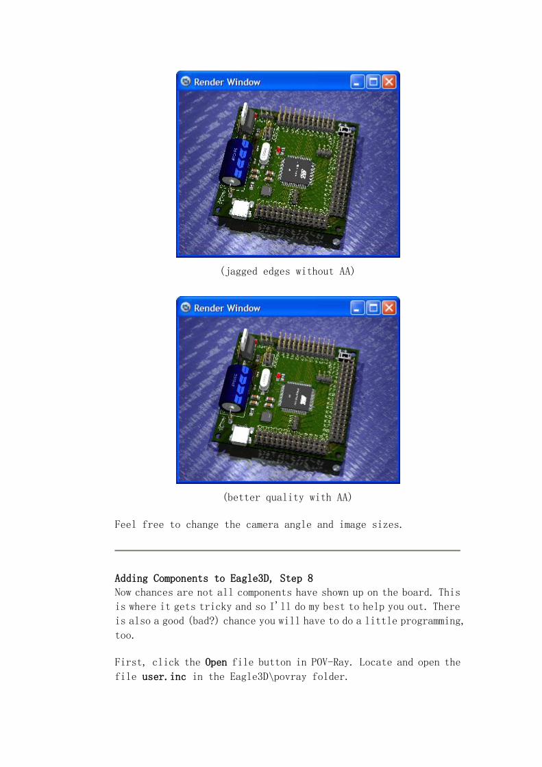
(jagged edges without AA)
(better quality with AA)
Feel free to change the camera angle and image sizes.
Adding Components to Eagle3D, Step 8
Now chances are not all components have shown up on the board. This
is where it gets tricky and so I'll do my best to help you out. There
is also a good (bad?) chance you will have to do a little programming,
too.
First, click the Open file button in POV-Ray. Locate and open the
file user.inc in the Eagle3D\povray folder.
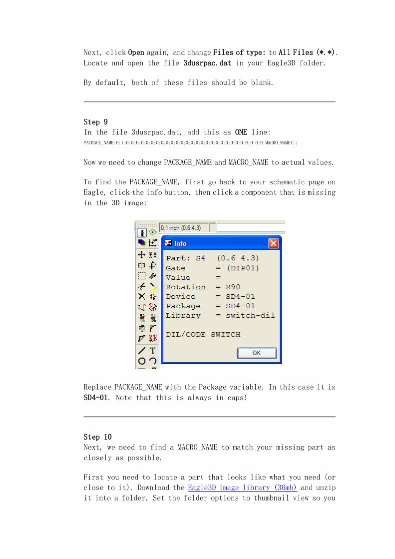
Next, click Open again, and change Files of type: to All Files (*.*).
Locate and open the file 3dusrpac.dat in your Eagle3D folder.
By default, both of these files should be blank.
Step 9
In the file 3dusrpac.dat, add this as ONE line: PACKAGE_NAME:0:1:0:0:0:0:0:0:0:0:0:0:0:0:0:0:0:0:0:0:0:0:0:0:0:0:0:0:0:0:MACRO_NAME(::
Now we need to change PACKAGE_NAME and MACRO_NAME to actual values.
To find the PACKAGE_NAME, first go back to your schematic page on
Eagle, click the info button, then click a component that is missing
in the 3D image:
Replace PACKAGE_NAME with the Package variable. In this case it is
SD4-01. Note that this is always in caps!
Step 10
Next, we need to find a MACRO_NAME to match your missing part as
closely as possible.
First you need to locate a part that looks like what you need (or
close to it). Download the Eagle3D image library (36mb) and unzip
it into a folder. Set the folder options to thumbnail view so you
can see them all. Locate a matching component (or as close as
possible), and copy the file name onto your clipboard (minus
the .png file extension).
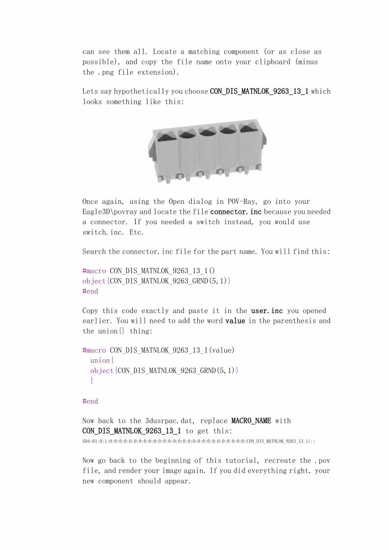
Lets say hypothetically you choose CON_DIS_MATNLOK_9263_13_1 which
looks something like this:
Once again, using the Open dialog in POV-Ray, go into your
Eagle3D\povray and locate the file connector.inc because you needed
a connector. If you needed a switch instead, you would use
switch.inc. Etc.
Search the connector.inc file for the part name. You will find this:
#macro CON_DIS_MATNLOK_9263_13_1()
object{CON_DIS_MATNLOK_9263_GRND(5,1)}
#end
Copy this code exactly and paste it in the user.inc you opened
earlier. You will need to add the word value in the parenthesis and
the union{} thing:
#macro CON_DIS_MATNLOK_9263_13_1(value)
union{
object{CON_DIS_MATNLOK_9263_GRND(5,1)}
}
#end
Now back to the 3dusrpac.dat, replace MACRO_NAME with
CON_DIS_MATNLOK_9263_13_1 to get this: SD4-01:0:1:0:0:0:0:0:0:0:0:0:0:0:0:0:0:0:0:0:0:0:0:0:0:0:0:0:0:0:0:CON_DIS_MATNLOK_9263_13_1(::
Now go back to the beginning of this tutorial, recreate the .pov
file, and render your image again. If you did everything right, your
new component should appear.
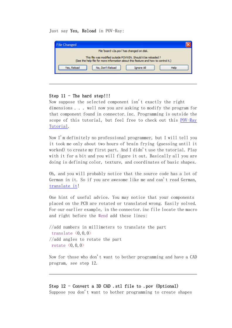
Just say Yes, Reload in POV-Ray:
Step 11 - The hard step!!!
Now suppose the selected component isn't exactly the right
dimensions . . . well now you are asking to modify the program for
that component found in connector.inc. Programming is outside the
scope of this tutorial, but feel free to check out this POV-Ray
Tutorial.
Now I'm definitely no professional programmer, but I will tell you
it took me only about two hours of brain frying (guessing until it
worked) to create my first part. And I didn't use the tutorial. Play
with it for a bit and you will figure it out. Basically all you are
doing is defining color, texture, and coordinates of basic shapes.
Oh, and you will probably notice that the source code has a lot of
German in it. So if you are awesome like me and can't read German,
translate it!
One hint of useful advice. You may notice that your components
placed on the PCB are rotated or translated wrong. Easily solved.
For our earlier example, in the connector.inc file locate the macro
and right before the #end add these lines:
//add numbers in millimeters to translate the part
translate <0,0,0>
//add angles to rotate the part
rotate <0,0,0>
Now for those who don't want to bother programming and have a CAD
program, see step 12.
Step 12 - Convert a 3D CAD .stl file to .pov (Optional)
Suppose you don't want to bother programming to create shapes
in .pov, and instead just want to convert you CAD files (from another
program) into .pov code. This can potentially save tons of time!
First, using your preferred CAD program, save your CAD file as a .stl.
This file type is an industry standard.
Next, download this small .stl to .pov conversion utility. For more
info and source code, feel free to check out the stl2pov homepage.
Unzip the file.
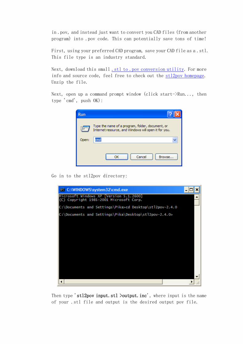
Next, open up a command prompt window (click start->Run..., then
type 'cmd', push OK):
Go in to the stl2pov directory:
Then type 'stl2pov input.stl >output.inc', where input is the name
of your .stl file and output is the desired output pov file.
Optionally, you can also type 'stl2pov input.stl|more' for more
stuff. Push enter.
It should now say 'Scanning...'
Wait until its done. I got lots of warnings but usually the file
will work anyway.
You now have a .inc file you can use with any macro. Just make sure
that its included:
Go back to Step 5 to add this line in POVRAY.INI:
Library_Path="C:\Documents and
Settings\Pika\Desktop\stl2pov-2.4.0"
(wherever the output.inc file is)
To view your new file and/or to include it, load up POVRay, select
the New icon, and paste this code into it:
#include "output.inc"
background {color rgb 1}
light_source {<-100,1000,-1000> rgb 1}
global_settings {
assumed_gamma 2
}
camera {
orthographic
location <10,10,-10> scale 0.2
look_at <2,0,2>
}
object {
m_ascii
texture {
pigment {color <1,0,0>}
finish {phong 0.5}
}
}
Save this new DrawSTL.pov file wherever.
Now just Render it as described in Step 6 and higher.