Embed Size (px)
Citation preview
Copyright European CommProvided by IHS under liceNo reproduction or network
--`,,```,,,,````-`-`,,`,,`,`,,`---
BRITISH STANDARD
BS EN 474-1:2006Earth-moving machinery — Safety —Part 1: General requirements
The European Standard EN 474-1:2006 has the status of a British Standard
ICS 53.100
�������������� ���������������������������������������������������ittee for Standardization nse with CEN
Not for Resaleing permitted without license from IHS
BS EN 474-1:2006
CopProNo
--`,,```,,,,````-`-`,,`,,`,`,,`---
This British Standard was published under the authority of the Standards Policy and Strategy Committee on 28 February 2007
© BSI 2007
ISBN 978 0 580 50151 7
yright European Committee for Standardization vided by IHS under license with CENreproduction or networking permitted without license from
National foreword
This British Standard was published by BSI. It is the UK implementation of EN 474-1:2006. It supersedes BS EN 474-1:1995, which will be withdrawn on 1 November 2008.The UK participation in its preparation was entrusted by Technical Committee B/513, Construction equipment and plant and site safety, to Subcommittee B/513/1, Earth moving machinery (International).A list of organizations represented on B/513/1 can be obtained on request to its secretary.The transition period is to allow stock of products manufactured to BS EN 474-1:1995 to be exhausted and for manufacturers to adopt the requirements of the revised standard.This publication does not purport to include all the necessary provisions of a contract. Users are responsible for its correct application.Compliance with a British Standard cannot confer immunity from legal obligations.
Amendments issued since publication
Amd. No. Date Comments
Not for ResaleIHS
EUROPEAN STANDARD
NORME EUROPÉENNE
EUROPÄISCHE NORM
EN 474-1
November 2006
ICS 53.100 Supersedes EN 474-1:1994
English Version
Earth-moving machinery - Safety - Part 1: General requirements
Engins de terrassement - Sécurité - Partie 1: Prescriptionsgénérales
Erdbaumaschinen - Sicherheit - Teil 1: AllgemeineAnforderungen
This European Standard was approved by CEN on 17 April 2006.
CEN members are bound to comply with the CEN/CENELEC Internal Regulations which stipulate the conditions for giving this EuropeanStandard the status of a national standard without any alteration. Up-to-date lists and bibliographical references concerning such nationalstandards may be obtained on application to the Central Secretariat or to any CEN member.
This European Standard exists in three official versions (English, French, German). A version in any other language made by translationunder the responsibility of a CEN member into its own language and notified to the Central Secretariat has the same status as the officialversions.
CEN members are the national standards bodies of Austria, Belgium, Cyprus, Czech Republic, Denmark, Estonia, Finland, France,Germany, Greece, Hungary, Iceland, Ireland, Italy, Latvia, Lithuania, Luxembourg, Malta, Netherlands, Norway, Poland, Portugal, Romania,Slovakia, Slovenia, Spain, Sweden, Switzerland and United Kingdom.
EUROPEAN COMMITTEE FOR STANDARDIZATIONC OM ITÉ EUR OP ÉEN DE NOR M ALIS AT IONEUROPÄISCHES KOMITEE FÜR NORMUNG
Management Centre: rue de Stassart, 36 B-1050 Brussels
© 2006 CEN All rights of exploitation in any form and by any means reservedworldwide for CEN national Members.
Ref. No. EN 474-1:2006: E
Copyright European Committee for Standardization Provided by IHS under license with CEN
Not for ResaleNo reproduction or networking permitted without license from IHS
--`,,```,,,,````-`-`,,`,,`,`,,`---
EN 474-1:2006 (E)
2
Contents Page
Foreword..............................................................................................................................................................4 Introduction .........................................................................................................................................................5 1 Scope ......................................................................................................................................................6 2 Normative references ............................................................................................................................6 3 Terms and definitions ...........................................................................................................................9 4 List of significant hazards ..................................................................................................................10 5 Safety requirements and/or measures ..............................................................................................10 6 Verification of safety requirements/measures..................................................................................29 7 Information for use ..............................................................................................................................29 Annex A (normative) List of significant hazards ..........................................................................................34 Annex B (normative) Requirements for attachment and attachment bracket...........................................38 Annex C (informative) Requirements for no-text safety signs ...................................................................40 Annex D (normative) Requirements for elevating operator's station.........................................................42 Annex E (normative) Requirements for lifting device(s) used for object handling application ..............44 Annex F (normative) Requirements for earth-moving machinery used in underground working in
non-explosive atmosphere .................................................................................................................50 Annex ZA (informative) Relationship between this European Standard and the Essential
Requirements of EU Directive 98/37/EC ............................................................................................52 Bibliography ......................................................................................................................................................53
Figures
Figure 1 — Minimum clearance of lower limbs at access to the operator's station on machines with articulated steering......................................................................................................... 11
Figure 2 — Dimensions access step ............................................................................................................. 12
Figure 3 — Location of measuring points..................................................................................................... 15
Figure 4 — Position of antenna relative to earth-moving machinery with diesel engines ...................... 25
Figure 5 — Position of antenna relative to earth-moving machinery with spark ignition engine........... 25
Figure C.1 — ”Safety alert symbol” ............................................................................................................... 41
Figure C.2 — "Read operation manual" ........................................................................................................ 41
Figure C.3 — "Crushing hazards".................................................................................................................. 41
Figure C.4 — "Cutting hazards" ..................................................................................................................... 41
Figure C.5 — "Hot surfaces" .......................................................................................................................... 41
Copyright European Committee for Standardization Provided by IHS under license with CEN
Not for ResaleNo reproduction or networking permitted without license from IHS
--`,,```,,,,````-`-`,,`,,`,`,,`---
EN 474-1:2006 (E)
3
Figure C.6 — Emergency exit..........................................................................................................................41
Figure E.1 — Sling guidance over the back-wall of the bucket ...................................................................45
Figure E.2 — Load direction............................................................................................................................46
Figure E.3 — Safety latch ................................................................................................................................47
Figure E.4 — Load direction (example for test bed) .....................................................................................48
Tables
Table 1 — Space envelope height related to machine classification .........................................................14
Table A.1 — List of significant hazards .........................................................................................................34
Copyright European Committee for Standardization Provided by IHS under license with CEN
Not for ResaleNo reproduction or networking permitted without license from IHS
--`,,```,,,,````-`-`,,`,,`,`,,`---
EN 474-1:2006 (E)
4
Foreword
This document (EN 474-1:2006) has been prepared by Technical Committee CEN/TC 151 “Construction equipment and building material machines — Safety”, the secretariat of which is held by DIN.
This European Standard shall be given the status of a national standard, either by publication of an identical text or by endorsement, at the latest by May 2007, and conflicting national standards shall be withdrawn at the latest by November 2008.
This European Standard supersedes EN 474-1:1994.
This document has been prepared under a mandate given to CEN by the European Commission and the European Free Trade Association, and supports essential requirements of EU Directive.
For relationship with EU Directive, see informative Annex ZA, which is an integral part of this document.
EN 474 "Earth-moving machinery — Safety" comprises the following parts:
Part 1: General requirements
Part 2: Requirements for tractor-dozers
Part 3: Requirements for loaders
Part 4: Requirements for backhoe-loaders
Part 5: Requirements for hydraulic excavators
Part 6: Requirements for dumpers
Part 7: Requirements for scrapers
Part 8: Requirements for graders
Part 9: Requirements for pipelayers
Part 10: Requirements for trenchers
Part 11: Requirements for earth and landfill compactors
Part 12: Requirements for cable excavators
For specific machines covered by other parts of the standard, this European Standard is intended for use in combination with relevant other parts of the series.
According to the CEN/CENELEC Internal Regulations, the national standards organizations of the following countries are bound to implement this European Standard: Austria, Belgium, Cyprus, Czech Republic, Denmark, Estonia, Finland, France, Germany, Greece, Hungary, Iceland, Ireland, Italy, Latvia, Lithuania, Luxembourg, Malta, Netherlands, Norway, Poland, Portugal, Romania, Slovakia, Slovenia, Spain, Sweden, Switzerland and the United Kingdom.
Copyright European Committee for Standardization Provided by IHS under license with CEN
Not for ResaleNo reproduction or networking permitted without license from IHS
--`,,```,,,,````-`-`,,`,,`,`,,`---
EN 474-1:2006 (E)
5
Introduction
This part of EN 474 is a type C standard as stated in EN ISO 12100-1:2003.
The machinery concerned and the extent to which hazards, hazardous situations and events are covered are indicated in the scope of this European Standard.
When provisions of this type C standard are different from those which are stated in type A or B standards, the provisions of this type C standard take precedence over the provisions of the other standards, for machines that have been designed and built according to the provisions of this type C standard.
Copyright European Committee for Standardization Provided by IHS under license with CEN
Not for ResaleNo reproduction or networking permitted without license from IHS
--`,,```,,,,````-`-`,,`,,`,`,,`---
EN 474-1:2006 (E)
6
1 Scope
This part of EN 474 specifies the general safety requirements for earth-moving machinery1) described in EN ISO 6165:2006, except rollers and horizontal directional drill.
NOTE 1 Rollers are covered by EN 500.
NOTE 2 Horizontal directional drill are covered by EN 791.
This part also applies to derivative machinery (see 3.1.2) designed primarily for use with equipment to loosen, pick-up, move, transport, distribute and grade earth and rock.
This part gives the common safety requirements for earth-moving machinery families and is intended to be used in conjunction with one of the EN 474 parts 2 to 12. These machine specific parts (EN 474-2 to -12) do not repeat the requirements from EN 474-1, but add or replace the requirements for the family in question.
NOTE 3 The requirements specified in this part of the standard are common to two or more families of earth-moving machinery.
Specific requirements in EN 474 parts 2 to 12 take precedence over the respective requirements of EN 474-1.
For multipurpose machinery the parts of the standard that cover the specific functions and applications have to be used e. g. a compact loader also used as a trencher shall use the relevant requirements of EN 474 parts 1, 3 and 10.
The standard also covers general requirements for attachments intended to be used with earth moving machine families covered in the scope.
This European Standard does not deal with the electrical hazards related to the main circuits and drives of machinery when the principal source of energy is electrical.
This European Standard deals with all significant hazards, hazardous situations and events relevant to earth-moving machinery, when used as intended and under conditions of misuse which are reasonably foreseeable by the manufacturer (see Clause 4). This European Standard specifies the appropriate technical measures to eliminate or reduce risks arising from the significant hazards, hazardous situations and events during commissioning, operation and maintenance of earth-moving machinery.
This European Standard is not applicable to earth moving machines, which are manufactured before the date of publication of this European Standard by CEN.
2 Normative references
The following referenced documents are indispensable for the application of this European Standard. For dated references, only the edition cited applies. For undated references, the latest edition of the referenced document (including any amendments) applies.
EN 286-2:1992, Simple unfired pressure vessels designed to contain air or nitrogen — Part 2: Pressure vessels for air braking and auxiliary systems for motor vehicles and their trailers
EN 287-1:2004, Qualification test of welders — Fusion welding — Part 1: Steels
1) For travelling on public roads the national traffic regulations apply until harmonised requirements are available. (A CEN-standard is under preparation)
Copyright European Committee for Standardization Provided by IHS under license with CEN
Not for ResaleNo reproduction or networking permitted without license from IHS
--`,,```,,,,````-`-`,,`,,`,`,,`---
EN 474-1:2006 (E)
7
EN 954-1:1996, Safety of machinery — Safety-related parts of control systems — Part 1: General principles for design
EN 982:1996, Safety of machinery — Safety requirements for fluid power systems and their components — Hydraulics
EN 1677-2:2000, Components for slings — Safety — Part 2: Forged steel lifting hooks with latch, Grade 8
EN 12643:1997, Earth-moving machinery — Rubber-tyred machines — Steering requirements (ISO 5010:1992, modified)
EN 13309:2000, Construction machinery — Electromagnetic compatibility of machines with internal electrical power supply
EN 13510:2000, Earth-moving machinery — Roll-over protective structures — Laboratory tests and performance requirements (ISO 3471:1994, including Amendment 1:1997 modified)
EN 13627:2000, Earth-moving machinery — Falling-object protective structures — Laboratory tests and performance requirements (ISO 3449:1992 modified)
EN 60529:1991, Degrees of protection provided by enclosures (IP code) (IEC 60529:1989)
EN 61310-1:1995, Safety of machinery — Indication, marking and actuation — Part 1: Requirements for visual, auditory and tactile signals (IEC 61310-1:1995)
EN ISO 2860:1999, Earth-moving machinery — Minimum access dimensions (ISO 2860:1992)
EN ISO 2867:2006, Earth-moving machinery — Access systems (ISO 2867:2006)
EN ISO 3411:1999, Earth-moving machinery — Human physical dimensions of operators and minimum operator space envelope (ISO 3411:1995)
EN ISO 3450:1996, Earth-moving machinery — Braking systems of rubber-tyred machines — System and performance requirements and test procedures (ISO 3450:1996)
EN ISO 3457:2003, Earth-moving machinery — Guards — Definitions and requirements (ISO 3457:2003)
EN ISO 4871:1996, Acoustics — Declaration and verification of noise emission values of machinery and equipment (ISO 4871:1996)
EN ISO 5353:1998, Earth-moving machinery, and tractors and machinery for agriculture and forestry — Seat index point (ISO 5353:1995)
EN ISO 6165:2006, Earth-moving machinery — Basic types — Vocabulary Identification and terms and definitions (ISO 6165:2006)
EN ISO 6682:1995, Earth-moving machinery — Zones of comfort and reach for controls (ISO 6682:1986 including Amendment 1:1989)
EN ISO 6683:2005, Earth-moving machinery — Seat belts and seat belt anchorages — Performance requirements and tests (ISO 6683:2005)
EN ISO 7096:2000, Earth-moving machinery — Laboratory evaluation of operator seat vibration (ISO 7096:2000)
EN ISO 12100-1:2003, Safety of machinery — Basic concepts, general principles for design — Part 1: Basic terminology, methodology (ISO 12100-1:2003)
Copyright European Committee for Standardization Provided by IHS under license with CEN
Not for ResaleNo reproduction or networking permitted without license from IHS
--`,,```,,,,````-`-`,,`,,`,`,,`---
EN 474-1:2006 (E)
8
EN ISO 12100-2:2003, Safety of machinery — Basic concepts, general principles for design — Part 2: Technical principles (ISO 12100-2:2003)
EN ISO 13732-1:2006, Ergonomics of the thermal environment - Methods for the assessment of human responses to contact with surfaces - Part 1: Hot surfaces (ISO 13732-1:2006)
ISO 3795:1989, Road vehicles, and tractors and machinery for agriculture and forestry — Determination of burning behaviour of interior materials
ISO 3864-1:2002, Graphical symbols — Safety colours and safety signs — Part 1: Design principles for safety signs in work places and public areas
ISO 3864-2:2004, Graphical symbols — Safety colours and safety signs — Part 2: Design principles for product safety labels
ISO 4250-3:1997, Earth-mover tyres and rims — Part 3: Rims
ISO 5006:2006, Earth-moving machinery — Operator's field of view — Test method and performance criteria
ISO 6011:2003, Earth-moving machinery — Visual display of machine operation
ISO 6014:1986, Earth-moving machinery — Determination of ground speed
ISO 6016:1998, Earth-moving machinery — Methods of measuring the masses of whole machines, their equipment and components
ISO/DIS 6395:2004, Earth-moving machinery — Determination of sound power level noise emissions — Dynamic test conditions
ISO/DIS 6396:2004, Earth-moving machinery — Determination of emission sound pressure level at operator's position — Dynamic test conditions
ISO 6405-1:2004, Earth-moving machinery — Symbols for operator controls and other displays — Part 1: Common symbols
ISO 6405-2:1993, Earth-moving machinery — Symbols for operator controls and other displays — Part 2: Specific symbols for machines, equipment and accessories
ISO 6749:1984, Earth-moving machinery — Preservation and storage
ISO 8643:1997, Earth-moving machinery — Hydraulic excavator and backhoe loader boom-lowering control device — Requirements and tests
ISO 9533:1989, Earth-moving machinery — Machine mounted forward and reverse audible warning alarm — Sound test method
ISO 10263-2:1994, Earth-moving machinery — Operator enclosure environment — Part 2: Air filter test
ISO 10263-3:1994, Earth-moving machinery — Operator enclosure environment — Part 3: Operator enclosure pressurization test method
ISO 10264:1990, Earth-moving machinery — Key-locked starting systems
ISO 10265:1998, Earth-moving machinery — Crawler machines — Performance requirements and test procedures for braking systems
ISO 10532:1995, Earth-moving machinery — Machine-mounted retrieval device — Performance requirements
Copyright European Committee for Standardization Provided by IHS under license with CEN
Not for ResaleNo reproduction or networking permitted without license from IHS
--`,,```,,,,````-`-`,,`,,`,`,,`---
EN 474-1:2006 (E)
9
ISO 10533:1993, Earth-moving machinery — Lift-arm support devices
ISO 10570:2004, Earth-moving machinery — Articulated frame lock — Performance requirements
ISO 10968:2004, Earth-moving machinery — Operator's controls
ISO 11112:1995, Earth-moving machinery — Operator's seat — Dimensions and requirements
ISO 11862:1993, Earth-moving machinery — Auxiliary starting aid electrical connector
ISO 12508:1994, Earth-moving machinery — Operator station and maintenance areas — Bluntness of edges
ISO 12509:2004, Earth-moving machinery — Lighting, signalling and marking lights, and reflex-reflector devices
ISO 13333:1994, Earth-moving machinery — Dumper body support and operator's cab tilt support devices
ISO 14396:2002, Reciprocating internal combustion engines — Determination and method for the measurement of engine power — Additional requirements for exhaust emission tests in accordance with ISO 8178
ISO 14401-1:2004, Earth-moving machinery — Field of vision of surveillance and rear-view mirrors — Part 1: Test methods
ISO 14401-2:2004, Earth-moving machinery — Field of vision of surveillance and rear-view mirrors — Part 2: Performance criteria
ISO 15817:2005, Earth-moving machinery — Safety requirements for remote operator control
ISO/DIS 15998:2005, Earth-moving machinery — Machine-control systems (MCS) using electronic components — Performance criteria and tests for functional safety
3 Terms and definitions
For the purposes of this European Standard, the terms and definitions given in EN ISO 12100-1:2003 and the following apply.
Earth-moving machinery and their families are defined in EN ISO 6165:2006.
NOTE Definitions used in EN and ISO standards referred to in this European Standard are also valid for this document.
3.1 earth-moving machinery self-propelled or towed machine on wheels, crawler or legs, having equipment and/or attachment (working tool), primarily designed to perform excavating, loading, transporting, spreading, compacting or trenching of earth, rock or similar materials
NOTE An earth-moving machine is normally operated by a ride-on operator but can also be remote – or pedestrian –controlled.
3.1.1 compact machine earth-moving machinery having an operating mass (see ISO 6016:1998) of 4 500 kg or less, or compact excavators having an operating mass (see ISO 6016:1998) of 6 000 kg or less
Copyright European Committee for Standardization Provided by IHS under license with CEN
Not for ResaleNo reproduction or networking permitted without license from IHS
--`,,```,,,,````-`-`,,`,,`,`,,`---
EN 474-1:2006 (E)
10
3.1.2 derivative machinery earth-moving machinery fitted with equipment and/or attachment which modifies its function
NOTE For the European Economic Area (EEA) the equipment or attachment or a piece of equipment as defined in ISO 6016:1998 which modifies the function of the machine and is intended to be assembled by the operator can be "interchangeable equipment" in the sense of the Machinery Directive.
3.2 attachment (working tool) component or assembly of components, which can be mounted onto the base machine or equipment (see ISO 6746-1:2003, ISO 6746-2:2003 and ISO 6016:1998) for a specific use
3.3 attachment bracket device to facilitate quick interchange of attachments
3.4 object handling application of earth-moving machinery comprising lifting, lowering and transporting of a load by use of lifting accessories, whereby the assistance of a person or the operator of the machine is required for hooking, unhooking or stabilising (whilst transporting) the load
NOTE 1 If the load is picked-up by a self-acting device and no assistance of a person is required for hooking, unhooking and stabilising the load, this work is considered as usual earth-moving application.
NOTE 2 Lifting accessories are, e. g., wire ropes, chains or textile straps; loads in object handling application are, e. g., pipes, vessels; self-acting devices are, e. g., grabs, clamshell buckets, log clamps, vacuum lifting device, magnetic plate and fork.
3.5 maximum rated operating/lift capacity in object handling maximum capacity which can be lifted at least in one position of the working range as specified by the manufacturer (e. g. on the rated object handling capacity table) in the most stable configuration (e. g. outriggers down)
NOTE The term "rated operating capacity" is defined in ISO 14397-1:2002 and used in EN 474-3 and EN 474-4. The term "rated lift capacity" is defined in ISO 10567:1992 and used in EN 474-5. Both terms are equivalent.
4 List of significant hazards
See Annex A.
NOTE Annex A (normative) contains all the significant hazards, hazardous situations and events, as far as they are dealt with in this European Standard, identified by risk assessment as common to two or more machinery families and which require action to eliminate or reduce the risk.
5 Safety requirements and/or measures
5.1 General
Earth-moving machinery shall comply with the safety requirements and/or protective measures of this European Standard, as far as not modified by requirements of the relevant specific part of the standard series. In addition, the machine shall be designed according to the principles of EN ISO 12100-1:2003 and EN ISO 12100-2:2003 for hazards relevant but not significant which are not dealt with by this European Standard.
Copyright European Committee for Standardization Provided by IHS under license with CEN
Not for ResaleNo reproduction or networking permitted without license from IHS
--`,,```,,,,````-`-`,,`,,`,`,,`---
EN 474-1:2006 (E)
11
5.2 Access
5.2.1 General requirements
Adequate access systems shall be provided to the operator's station and areas where routine maintenance has to be performed by the operator as described in the operator's manual. Access system shall comply with EN ISO 2867:2006.
Effect of mud on the means of access shall be minimised by adequate design.
5.2.2 Access to articulated machines
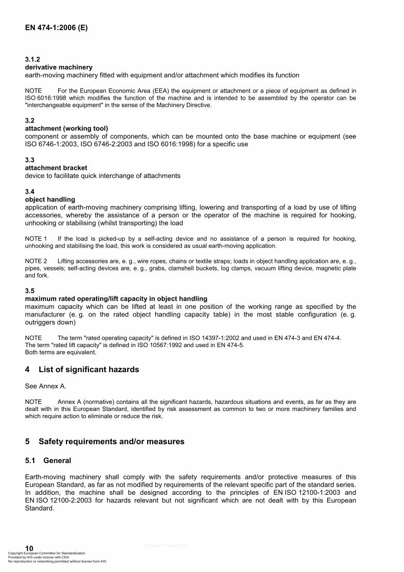
On machines with articulated frames and in the fully articulated steering position, a minimum clearance of 150 mm for the lower limbs shall be provided between firm structures or components with relative movement in the path of the access systems to the operator's station, as illustrated in Figure 1.
Dimensions in millimetres
Figure 1 — Minimum clearance of lower limbs at access to the operator's station on machines with articulated steering
5.2.3 Access system on crawler machines with step(s)
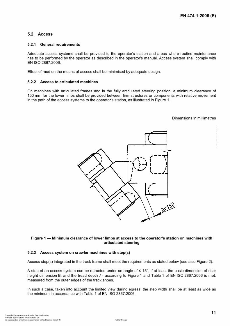
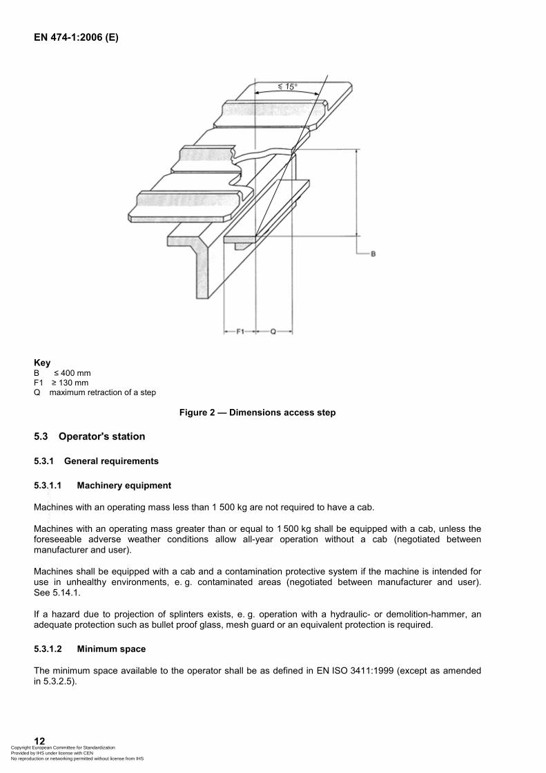
Access step(s) integrated in the track frame shall meet the requirements as stated below (see also Figure 2).
A step of an access system can be retracted under an angle of ≤ 15°, if at least the basic dimension of riser height dimension B, and the tread depth F1 according to Figure 1 and Table 1 of EN ISO 2867:2006 is met, measured from the outer edges of the track shoes.
In such a case, taken into account the limited view during egress, the step width shall be at least as wide as the minimum in accordance with Table 1 of EN ISO 2867:2006.
Copyright European Committee for Standardization Provided by IHS under license with CEN
Not for ResaleNo reproduction or networking permitted without license from IHS
--`,,```,,,,````-`-`,,`,,`,`,,`---
EN 474-1:2006 (E)
12
Key B ≤ 400 mm F1 ≥ 130 mm Q maximum retraction of a step
Figure 2 — Dimensions access step
5.3 Operator's station
5.3.1 General requirements
5.3.1.1 Machinery equipment
Machines with an operating mass less than 1 500 kg are not required to have a cab.
Machines with an operating mass greater than or equal to 1 500 kg shall be equipped with a cab, unless the foreseeable adverse weather conditions allow all-year operation without a cab (negotiated between manufacturer and user).
Machines shall be equipped with a cab and a contamination protective system if the machine is intended for use in unhealthy environments, e. g. contaminated areas (negotiated between manufacturer and user). See 5.14.1.
If a hazard due to projection of splinters exists, e. g. operation with a hydraulic- or demolition-hammer, an adequate protection such as bullet proof glass, mesh guard or an equivalent protection is required.
5.3.1.2 Minimum space
The minimum space available to the operator shall be as defined in EN ISO 3411:1999 (except as amended in 5.3.2.5).
Copyright European Committee for Standardization Provided by IHS under license with CEN
Not for ResaleNo reproduction or networking permitted without license from IHS
--`,,```,,,,````-`-`,,`,,`,`,,`---
EN 474-1:2006 (E)
13
For compact machines the minimum space envelope width (dimension 920 mm in EN ISO 3411:1999, Figure 5) may be reduced to 650 mm.
The minimum space and location of the controls at the operator's station shall meet the requirements specified in EN ISO 6682:1995.
5.3.1.3 Moving parts
Measures shall be taken to avoid accidental contact from the operating position with moving parts, e. g. the wheels, or tracks or working equipment and/or attachment in accordance with relevant subclauses of 5.14.
5.3.1.4 Engine exhaust
The engine exhaust system shall release the exhaust gas away from the operator and the air inlet of the cab.
5.3.1.5 Instruction storage
A space intended for the safekeeping of the operator’s manual and other instructions shall be provided near the operator's station. The space shall be lockable, unless the operator's station can be locked.
5.3.1.6 Sharp edges
The operator's space within the operator's station, e. g. ceiling, inner walls, instrument panels and access to the operator's station shall not present any sharp edges or acute angles/corners. Radius of corners and bluntness of edges shall comply with ISO 12508:1994 to avoid sharp edges (see also 5.14.6).
5.3.2 Operator's station equipped with a cab
5.3.2.1 Climatic conditions
The cab shall protect the operator against foreseeable adverse climatic conditions. Provisions shall be made to install a ventilation system, an adjustable heating system and a system for defrosting windows. For details see 5.3.2.6 to 5.3.2.8.
5.3.2.2 Pipes and hoses
Pipes and hoses located inside the cab which contain fluids that are dangerous, for example because of their pressure (greater than 5 MPa), temperature (greater than 50°C) shall be guarded, see EN ISO 3457:2003, Clause 9.
NOTE As far as possible pipes and hoses should be placed outside the cab.
Parts or components placed between pipes or hoses and the operator, which divert e. g. a hazardous spray of fluid, can be considered as a sufficient protection device.
5.3.2.3 Primary access opening
A primary access opening shall be provided. The dimensions shall comply with EN ISO 2867:2006, Figure 4 and Table 4.
5.3.2.4 Alternative opening (emergency exit)
An alternative opening shall be provided on a side other than that of the primary opening. The dimensions shall comply with EN ISO 2867:2006, Clause 11. A window panel or another door is acceptable if they are easy to open or remove without the use of keys or tools. Latches may be used if they can be opened from the inside without the use of keys or tools. The break of a suitable size of glass pane is considered equivalent to
Copyright European Committee for Standardization Provided by IHS under license with CEN
Not for ResaleNo reproduction or networking permitted without license from IHS
--`,,```,,,,````-`-`,,`,,`,`,,`---
EN 474-1:2006 (E)
14
an alternative opening. In such a case the necessary pane hammer, immediately accessible to the operator, shall be provided and stored in the cab.
When the window panel is used as an emergency exit it shall bear an appropriate marking according to Figure 8 of EN 61310-1:1995.
5.3.2.5 Space envelope height
The minimum space envelope height R1 as defined in Figure 5 of EN ISO 3411:1999 and measured from the seat index point (SIP), as defined in EN ISO 5353:1998, shall meet the values given in Table 1.
Table 1 — Space envelope height related to machine classification
Machine classification Minimum space envelope height
mm from the SIP
Compact machines 920
All other machines 1 000
The minimum dimensions given in Table 1 are also required for machines having a front or rear window which are located (in an opened position) above the operator's seat.
5.3.2.6 Heating and ventilation system
If a heating system is fitted it shall either:
a) comply with ISO 10263-4:1994, or
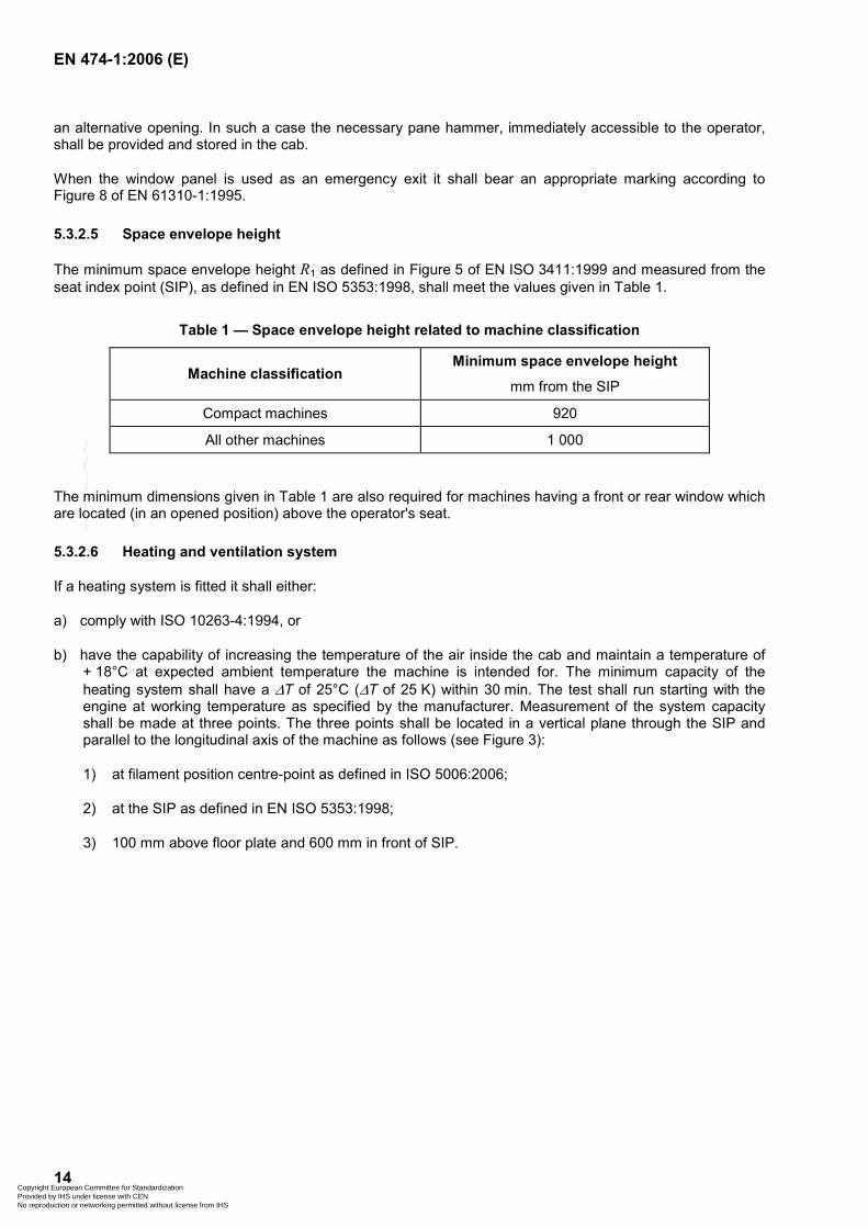
b) have the capability of increasing the temperature of the air inside the cab and maintain a temperature of + 18°C at expected ambient temperature the machine is intended for. The minimum capacity of the heating system shall have a ∆T of 25°C (∆T of 25 K) within 30 min. The test shall run starting with the engine at working temperature as specified by the manufacturer. Measurement of the system capacity shall be made at three points. The three points shall be located in a vertical plane through the SIP and parallel to the longitudinal axis of the machine as follows (see Figure 3):
1) at filament position centre-point as defined in ISO 5006:2006;
2) at the SIP as defined in EN ISO 5353:1998;
3) 100 mm above floor plate and 600 mm in front of SIP.
Copyright European Committee for Standardization Provided by IHS under license with CEN
Not for ResaleNo reproduction or networking permitted without license from IHS
--`,,```,,,,````-`-`,,`,,`,`,,`---
EN 474-1:2006 (E)
15
Figure 3 — Location of measuring points
c) Alternatively, the heating capacity can be determined by calculation.
The ventilation system shall be capable of providing the cab with filtered fresh air at the minimum of 43 m3/h. The filter shall be tested according to ISO 10263-2:1994.
NOTE The filter element selection depends on the intended operating environment conditions.
5.3.2.7 Defrosting system
Machine with a cab shall provide facilities to defrost the front and rear window(s), for example by means of a heating system or a particular defrosting device.
NOTE A testing method of windscreen defrosting system is described in ISO 10263-5:1994.
5.3.2.8 Pressurisation system
Where a cab is provided with a pressurisation system, it shall be tested according to ISO 10263-3:1994 and shall provide an interior relative pressure of at least 50 Pa.
5.3.2.9 Doors and windows
Doors, windows and flaps shall be securely held in their functional positions; measures shall be taken for preventing inadvertent opening. Doors shall be retained at their intended operating position(s) by a positive engagement device. A primary opening designed to be held securely open as an intended operating position, shall be releasable from the operator's station.
Windows shall be made of safety glass or other material which provides similar safety performance (see e. g. ECE R43).
Roof windows do not need additional mechanical safeguarding.
The front and rear window(s) shall be fitted with motorised windscreen wiper(s) and washer(s). The tank of the window washer(s) shall be easily accessible.
Copyright European Committee for Standardization Provided by IHS under license with CEN
Not for ResaleNo reproduction or networking permitted without license from IHS
--`,,```,,,,````-`-`,,`,,`,`,,`---
EN 474-1:2006 (E)
16
5.3.2.10 Inner lighting
The cab shall be fitted with a fixed inner lighting system and be able to function with the engine at a stop, to make it possible to illuminate the operator's station and to read the operation manual in darkness.
5.3.3 Roll-over protective structures (ROPS)
5.3.3.1 General
Earth-moving machinery shall be equipped with a roll-over protective structure (ROPS). The ROPS shall comply with EN 13510:2000.
When specific parts of the standard specify that a ROPS is not required for covered machines, anchorage points are not required.
5.3.3.2 ROPS for derivative machinery
For derivative machinery, the ROPS shall be designed taking into account the operating mass (see ISO 6016:1998) of the derivative machinery in the heaviest configuration as specified by the manufacturer.
5.3.4 Falling-object protective structures (FOPS)
Earth-moving machinery (for exceptions, see EN 13627:2000) shall be so designed that a falling-object protective structure (FOPS) can be fitted, when they are intended for applications where there is a risk of falling objects.
If FOPS is fitted it shall comply with EN 13627:2000.
If a provision for FOPS is required by specific parts of the standard, the manufacturer shall provide on demand the corresponding FOPS.
5.3.5 Elevating operator's station
See Annex D
5.3.6 Replacement of operator protective structure
In case any part of the protective structure (e. g. ROPS, TOPS, FOPS) is affected by a plastic deformation and/or rupture (e. g. by roll-over, tip-over or object impact), the protective structure has to be replaced according to manufacturer's specifications. See also 7.2.
5.4 Seats
5.4.1 Operator's seat
5.4.1.1 General requirement
Machinery with provision for a seated operator shall be fitted with an adjustable seat that supports the operator in a position, which allows the operator to control the machine under intended operating conditions.
5.4.1.2 Dimensions
The seat dimensions shall comply with ISO 11112:1995.
Copyright European Committee for Standardization Provided by IHS under license with CEN
Not for ResaleNo reproduction or networking permitted without license from IHS
--`,,```,,,,````-`-`,,`,,`,`,,`---
EN 474-1:2006 (E)
17
5.4.1.3 Adjustment
All adjustments to accommodate the operator's size shall comply with ISO 11112:1995, Table 1 and be adjustable without the use of any tool.
For compact machines (see 3.1.1) the following seat adjustments apply:
either the fore and aft adjustment (see ISO 11112:1995, Table 1, l2) shall be at least ± 35 mm or the corresponding adjustment of frequently used operator's controls shall be provided;
vertical adjustment (ISO 11112:1995, Table 1, h1) is not required.
5.4.1.4 Vibration
The operator's seat shall meet the requirements of EN ISO 7096:2000 with regard to its ability to reduce the vibration transmitted to the operator.
5.4.1.5 Restraint system
Machines fitted with ROPS or TOPS (tip over protective structure) shall have an operator restraint system that meets the requirements specified in EN ISO 6683:2005.
5.4.2 Additional seat
5.4.2.1 Instructor's seat
If an additional seat for an instructor is installed in the operator's station, it shall be padded and provide adequate space for the instructor. The instructor shall also have available a conveniently placed handhold.
5.4.2.2 Second operator's seat
If a second operator's seat is required for a specific machine, which can be frequently or alternatively used by the operator to perform the application of the machine, this seat shall fulfil the requirements for seats as specified in 5.4 and the safety structures as specified in 5.3.3 (ROPS) and 5.3.4 (FOPS).
5.5 Operator's controls and indicators
5.5.1 General
The controls (hand levers, pedals, switches etc.) and indicators of the machine, equipment, attachment, shall be chosen, designed, constructed and arranged according to ISO 10968:2004, so that:
a) they are of easy access, in accordance with EN ISO 6682:1995 and ISO 10968:2004;
b) neutral positions of controls shall be in accordance with 5.3 of ISO 10968:2004;
c) they are clearly identified (see ISO 6405-1:2004 and ISO 6405-2:1993) in the operator's station and explained in the operation manual (see 7.2);
d) the movement of the controls to activate the functions and indicators shall correspond to the intended effect or common practice whenever possible;
e) the normal engine stop device shall be within the zone of reach (see EN ISO 6682:1995);
f) when a control is designed and constructed to carry out several functions of the machine, e. g. keyboard, joystick control, the activated function shall be clearly identified;
Copyright European Committee for Standardization Provided by IHS under license with CEN
Not for ResaleNo reproduction or networking permitted without license from IHS
--`,,```,,,,````-`-`,,`,,`,`,,`---
EN 474-1:2006 (E)
18
g) for requirements on joy-sticks, see also ISO 10968:2004;
h) for safety related functions of control system(s) having no electronic components, the principles outlined in EN 954-1:1996 shall be used or methods giving similar protection.
5.5.2 Starting system
The starting system of earth-moving machinery shall be provided with a starting device (e. g. key) and shall comply with ISO 10264:1990 or have a similar protection.
Earth-moving machines shall be so designed that hazardous movement of the machine or its working equipment and/or attachment shall not be possible without action on the controls whilst starting the engine.
5.5.3 Inadvertent activation
Controls which can cause a hazard due to inadvertent activation shall be so arranged or deactivated or guarded as to minimise the risk, in particular when the operator gets into or out of the operator's station. The deactivation device shall either be self-acting or acting by compulsory actuation of the relevant device.
5.5.4 Pedals
Pedals shall have an appropriate size, shape and be adequately spaced. The pedals shall have a slip-resistant surface and be easy to clean.
If the pedals of an earth-moving machine have the same function (clutch, brake, and accelerator) as on a motor vehicle, they shall be arranged in the same manner to avoid the risk of confusion.
5.5.5 Emergency attachment lowering
If the engine is stopped it shall be possible to:
a) lower the equipment/attachment to the ground/frame;
b) see the equipment/attachment lowering from the operator actuating position of the lowering control;
c) release the residual pressure in each hydraulic and pneumatic circuit, which can cause a risk.
The means to lower the attachment and the device to release the residual pressure can be located outside the operator's station and shall be described in the operation manual.
5.5.6 Uncontrolled motion
Machine and equipment or attachment movement from the holding position, other than by actuation of the controls by the operator, due to drift or creep (e. g. by leaking) or when power supply stops, shall be limited to the extent that it can not create a risk to exposed persons.
5.5.7 Remote control
Remote operator controlled earth-moving machinery shall comply with the requirements as specified in ISO 15817:2005.
Copyright European Committee for Standardization Provided by IHS under license with CEN
Not for ResaleNo reproduction or networking permitted without license from IHS
--`,,```,,,,````-`-`,,`,,`,`,,`---
EN 474-1:2006 (E)
19
5.5.8 Control panels, indicators and symbols
5.5.8.1 Control panels
The operator shall be able to see from the operator's station, in both daylight and darkness, the necessary indicators to check the proper function of the machine. Glare shall be minimised.
5.5.8.2 Operating instrumentation
Control indicators for safe and proper operation of the machine, shall follow the safety colours and safety signs/requirements according to ISO 6011:2003.
5.5.8.3 Symbols
Symbols for use on operator controls and other displays on earth-moving machinery shall follow, e. g., ISO 6405-1:2004 or ISO 6405-2:1993.
5.5.9 Controls of ride-on machinery accessible from ground level
On ride-on machinery where controls are accessible from the ground, means shall be provided to minimise the possibility to actuate the controls from the ground (e. g. protection by door, guard or by locking systems).
5.6 Steering system
5.6.1 General
The steering system shall be such that the movement of the steering control shall correspond to the intended direction of steering.
5.6.2 Rubber-tyred machines
Steering system of rubber-tyred machinery with a forward/reverse travel speed greater than 20 km/h shall comply with EN 12643:1997.
5.6.3 Crawler machines
Steering system of crawler machines with a forward/reverse travel speed greater than 20 km/h shall be gradual.
5.7 Brake systems
Earth-moving machines shall be equipped with service brake system, secondary brake system and parking brake system, efficient under all conditions of service, load, speed, terrain and slope, according to the intended use of the machine.
Brake systems shall comply with the following requirements:
for wheeled machines with EN ISO 3450:1996;
for crawler machines with ISO 10265:1998.
Copyright European Committee for Standardization Provided by IHS under license with CEN
Not for ResaleNo reproduction or networking permitted without license from IHS
--`,,```,,,,````-`-`,,`,,`,`,,`---
EN 474-1:2006 (E)
20
5.8 Visibility
5.8.1 Operator's field of view
Earth-moving machines shall be designed in accordance with ISO 5006:2006 so that the operator has sufficient visibility from the operator's station in relation to the travel and work areas of the machine that are necessary for the intended use of the machine. The travel mode as specified in ISO 5006:2006 is considered to be representative for testing visibility in both travel and operating modes.
NOTE It is sufficient to measure the machine with the most challenging standard attachment within the limits of the intended use.
Earth-moving machines shall be equipped with rear view mirrors according to ISO 14401-1:2004 and ISO 14401-2:2004.
5.8.2 Lighting, signalling and marking lights, and reflex-reflector devices
Work lights and reflex-reflector devices shall be provided and shall comply with ISO 12509:2004. Lighting, signalling and marking lights, if provided, shall comply with the appropriate clauses of ISO 12509:2004.
5.9 Warning devices and safety signs
Earth-moving machinery shall be equipped with:
an audible warning device (horn) controlled from the operator's station, the A-weighed sound pressure level of which shall be greater than or equal to 93 dB. The value shall be measured 7 m from the foremost point of the machine with equipment/attachment in its travel position as defined in ISO/DIS 6395:2004. The test procedure shall be in accordance with ISO 9533:1989;
safety signs (see Annex C for examples. See also 7.1).
5.10 Tyres and rims
Rubber-tyred earth-moving machinery shall have tyre and rim load performance adapted to the purpose and application.
Rims shall have clear identification, e. g. see ISO 4250-3:1997.
5.11 Stability
Earth-moving machinery with working equipment and/or attachments and optional equipment shall be designed and constructed so that stability is provided under all intended operating conditions, as specified by the manufacturer in the operation manual.
Devices intended to increase the stability of earth-moving machinery in working mode (e. g. outriggers, oscillating axle locking) shall be fitted with interlocking devices, e. g. check valve which keeps them in position in case of hose failure or in case of oil leakage.
5.12 Object handling
5.12.1 Lifting device(s) for object handling
The lifting device(s) may be either fixed or removable. This device may be located on a bucket, on an arm or any other part of the machine or may be a separate device and shall be:
Copyright European Committee for Standardization Provided by IHS under license with CEN
Not for ResaleNo reproduction or networking permitted without license from IHS
--`,,```,,,,````-`-`,,`,,`,`,,`---
EN 474-1:2006 (E)
21
so located and designed that the risk of being damaged during normal earth moving operations is minimised;
designed so that hooking device prevents unintentional unhooking of the load.
The lifting device(s) shall meet the requirements of Annex E.
5.12.2 Lowering control device
Machines used in object handling application (see machine specific parts), which require a boom lowering control device, shall conform with ISO 8643:1997.
5.13 Noise
5.13.1 Noise reduction
5.13.1.1 Noise reduction at source at the design stage
Machinery shall be so designed and constructed that risks resulting from the emission of airborne noise are reduced to the lowest level taking account of technical progress and the availability of means of reducing noise, in particular, at source.
When designing machinery, the available information and technical measures to control noise at source shall be taken into account. Recommended practice for the design of low-noise machinery is given in EN ISO 11688-1:1998.
NOTE 1 EN ISO 11688-2:2000 gives useful information on noise generation mechanisms in machinery.
NOTE 2 For earth-moving machinery, the main sources of noise are the engine and the hydraulic components, the cooling system and the undercarriage especially for crawler machines. The engines are subject to an exhaust emission regulation without requirement for noise emission. The design of the earth-moving machinery has to take into account the evolution of the engines, which should stay at a similar level of noise emission but would create more heat.
NOTE 3 The majority of earth-moving machinery is subject to noise regulation since 1986.
5.13.1.2 Noise reduction by protective measures
In addition to 5.13.1.1, it is recommended to equip the machines with protective measures/devices to reduce the noise emitted.
For example, the following measures may be applied:
a cab as defined in 5.3;
enclosure of the engine(s) and cooling system;
exhaust mufflers.
5.13.1.3 Information on noise emission
Information on noise emission shall be given by the manufacturer in the operation manual, see 7.2.
Copyright European Committee for Standardization Provided by IHS under license with CEN
Not for ResaleNo reproduction or networking permitted without license from IHS
--`,,```,,,,````-`-`,,`,,`,`,,`---
EN 474-1:2006 (E)
22
5.13.2 Noise emission measurement
5.13.2.1 Sound power level
The sound power level for the different types of earth-moving machinery shall be measured according to ISO/DIS 6395:2004 unless otherwise stated in the machine specific parts of this standard.
NOTE Noise emission values obtained from measurements are the way to verify the result of the noise reduction measures taken at the design stage (see 5.13.1.1 and 5.13.1.2).
5.13.2.2 Emission sound pressure level at the operator's station
The emission sound pressure level at the operator's station for the different types of earth-moving machinery shall be measured according to ISO/DIS 6396:2004 unless otherwise stated in the machine specific parts of this standard.
NOTE 1 On machines fitted with a cab, the A-weighted emission sound pressure level at the operator's position should not exceed 85 dB.
NOTE 2 Noise emission values obtained from measurements are the way to verify the result of the noise reduction measures taken at the design stage (see 5.13.1.1 and 5.13.1.2).
5.14 Protective measures and devices
5.14.1 Contaminated area
If an earth-moving machine is intended to be used in a contaminated environment, special precautions to protect the operator (e. g. fresh air filter systems or system to provide breathing air to the operator) are needed if any hazard exists (see also 5.3.1.1).
5.14.2 Hot parts
Parts which are hot in operation shall be designed, constructed, positioned or provided with a thermal guard to minimise the risk of contact with hot parts and/or surfaces in close proximity to the primary opening, operating position and maintenance area according to EN ISO 13732-1:2006.
5.14.3 Moving parts
All moving parts which create a hazard shall be designed, constructed, positioned or provided with protection devices to minimise the risk of crushing, shearing and cutting.
5.14.4 Guards
Guards shall be designed to be securely held in place and prevent access to dangerous areas and parts where a hazard exists.
Engine compartment panels are regarded as guards.
Guards shall comply with EN ISO 3457:2003.
Movable guards shall as far as possible remain attached to the machine when open.
Movable guards shall be fitted with a support system (e. g. springs, gas cylinders) to secure them in opened position up to a wind speed of 8 m/s.
Copyright European Committee for Standardization Provided by IHS under license with CEN
Not for ResaleNo reproduction or networking permitted without license from IHS
--`,,```,,,,````-`-`,,`,,`,`,,`---
EN 474-1:2006 (E)
23
5.14.5 Articulated frame lock
Articulated machines shall be equipped with an articulated frame lock according to ISO 10570:2004.
5.14.6 Sharp edges and acute angles
Sharp angles and acute angles shall meet the requirements defined in ISO 12508:1994 in the areas which can be accessed during operation and daily maintenance, except for the area of the attachment. See also 5.3.1.6.
5.14.7 Fenders
Earth-moving machinery with a design speed according to ISO 6014:1986 greater than 25 km/h shall be equipped with fenders according to EN ISO 3457:2003 that protect the operator's station from debris ejected by the tyres or tracks if the risk exists.
Earth moving machines without cab shall have fenders that comply with EN ISO 3457:2003.
5.15 Retrieval, transportation, lifting and towing
5.15.1 Common use
The devices for retrieval, tie-down, lifting, and towing may be the same if allowed by the configuration of the machine.
5.15.2 Retrieval
Retrieval points shall be provided at the front and/or rear of the earth-moving machines according to ISO 10532:1995.
Attachment points for retrieving of the machine shall be described in the operation manual as well as permissible forces and correct use.
5.15.3 Tie-down
To transport earth-moving machinery safely, tie-down points to anchor the machine e.g. on a trailer, shall be provided and clearly identified on the machine (see ISO 6405-1:2004, symbol 7.27). Instructions for their use shall be included in the operation manual.
5.15.4 Lifting
Lifting points shall be provided and be designed for the operating mass in the heaviest configuration and shall be clearly identified on machines or subassemblies that are to be lifted in one piece.
The method of lifting heavy attachments, components and machines shall be described in the operation manual (see 7.2).
For lifting symbol, see ISO 6405-1:2004, symbol 7.23.
5.15.5 Towing
Towing device(s) (hooks, ears etc.) shall be provided on the machine. They shall comply with ISO 10532:1995. Their location, permissible forces, the correct use when towing as well as the maximum towing speed and distance shall be clearly specified in the operator's manual.
Copyright European Committee for Standardization Provided by IHS under license with CEN
Not for ResaleNo reproduction or networking permitted without license from IHS
--`,,```,,,,````-`-`,,`,,`,`,,`---
EN 474-1:2006 (E)
24
If a pin is part of the towing device, the pin shall be permanently attached to the device. The securing device for the pin shall not be detachable.
5.15.6 Transportation
Stabilisers, outriggers or other moveable devices that can cause a hazard during transportation or travelling shall be secured lockable in their transport position.
Instructions for secure locking shall be provided in the operation manual.
5.16 Electro-magnetic compatibility (EMC)
Earth-moving machines shall comply with the requirements of electromagnetic compatibility as specified in EN 13309:2000.
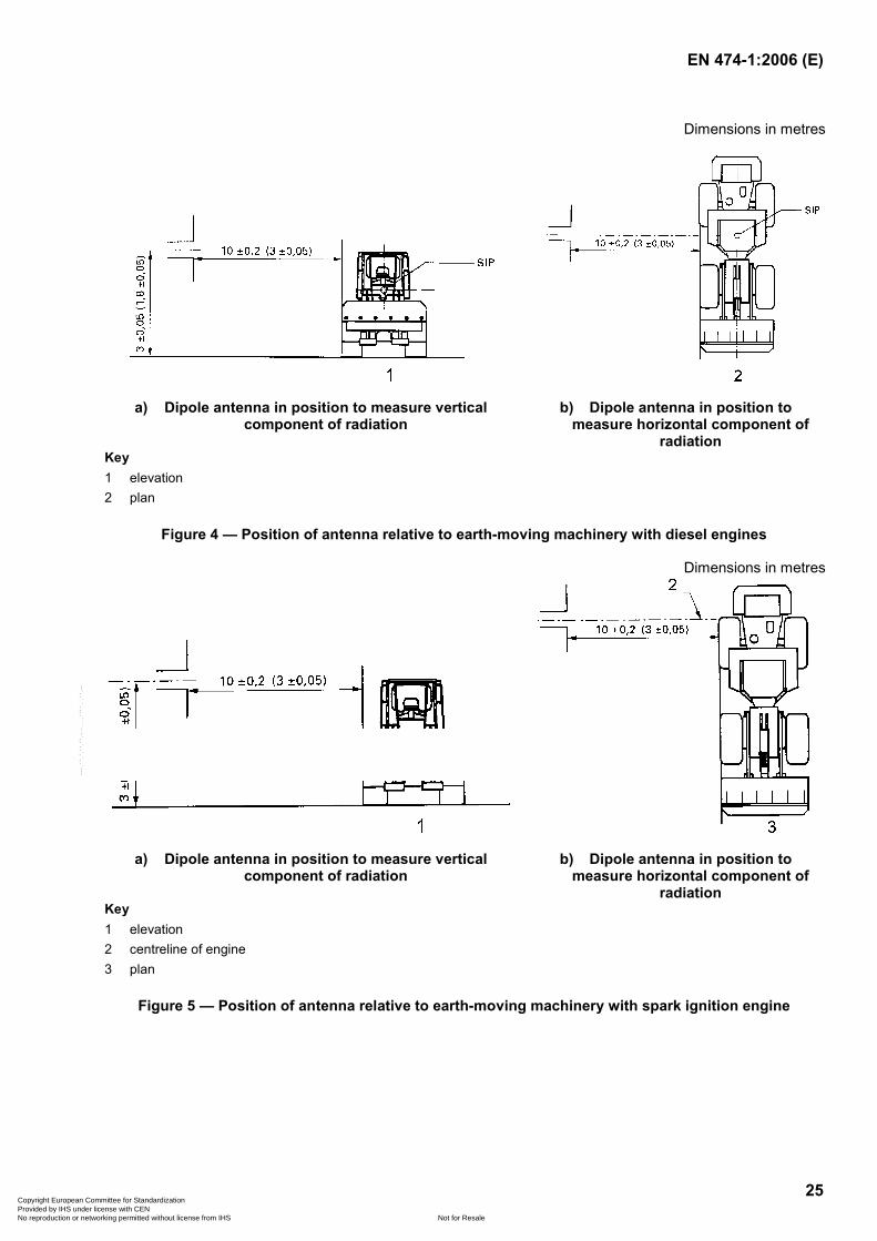
The antenna shall be located successively on the left- and right-hand sides of the earth-moving machine, with the antenna parallel to the plane of the longitudinal symmetry of earth-moving machine and in line with:
a) for diesel engines: the SIP (see EN ISO 5353:1998), see Figure 4;
b) for spark ignition engines: the engine mid-point, see Figure 5.
Copyright European Committee for Standardization Provided by IHS under license with CEN
Not for ResaleNo reproduction or networking permitted without license from IHS
--`,,```,,,,````-`-`,,`,,`,`,,`---
EN 474-1:2006 (E)
25
Dimensions in metres
a) Dipole antenna in position to measure vertical component of radiation
b) Dipole antenna in position to measure horizontal component of
radiation Key 1 elevation 2 plan
Figure 4 — Position of antenna relative to earth-moving machinery with diesel engines
Dimensions in metres
a) Dipole antenna in position to measure vertical component of radiation
b) Dipole antenna in position to measure horizontal component of
radiation Key 1 elevation 2 centreline of engine 3 plan
Figure 5 — Position of antenna relative to earth-moving machinery with spark ignition engine
Copyright European Committee for Standardization Provided by IHS under license with CEN
Not for ResaleNo reproduction or networking permitted without license from IHS
--`,,```,,,,````-`-`,,`,,`,`,,`---
EN 474-1:2006 (E)
26
5.17 Electrical and electronic systems
5.17.1 General
Electrical components and conductors shall be installed in such a way as to avoid damage from exposure to environmental conditions (corresponding to the intended use of the machine) which can cause deterioration. Electrical component insulation shall have flame-retardant properties. Lead-through e. g. through frames and bulkheads, shall be protected from abrasion.
Electrical wires/cables not protected by over-current devices shall not be strapped in direct contact with pipes and hoses containing fuel.
Safety related electrical function shall comply with ISO/DIS 15998:2005.
5.17.2 Degree of protection
Depending on the location/installation of electrical and electronic components, the following degrees of protection are required:
all components installed exterior to the machine or directly exposed to the environment shall have a minimum degree of protection which corresponds to IP 55 according to EN 60529:1991;
for all components installed in the operator's cab or protected against the environment, the protection shall be designed and executed to safeguard a correct function under expected and intended conditions.
5.17.3 Electrical connections
In order to avoid incorrect connections, electric wires and cables used to connect components in electric circuits shall be marked and identified.
This requirement does not apply to electrical circuits of anti-theft systems.
NOTE ISO 9247:1990 should be used as guidance.
5.17.4 Over-current protective devices
Electric equipment except the starter motor, alternator and pre-heater, shall be protected with an over-current device (e. g. fuse) or other device giving the same protection.
5.17.5 Batteries
Batteries shall be firmly attached in a ventilated space. The batteries shall be provided with handles and/or grips.
Batteries and/or battery locations shall be designed and built or covered to minimise any hazard to the operator caused by battery acid or acid vapours in the event of overturning of the machine.
Live parts (not connected to the frame) and/or connectors shall be covered with insulation material.
NOTE The location should have an easy access. Batteries should be easily removable
5.17.6 Battery disconnection
It shall be possible to disconnect batteries easily e.g. by a quick coupling or an accessible isolator switch. The symbol according to ISO 6405-1:2004 shall be used for identification.
Copyright European Committee for Standardization Provided by IHS under license with CEN
Not for ResaleNo reproduction or networking permitted without license from IHS
--`,,```,,,,````-`-`,,`,,`,`,,`---
EN 474-1:2006 (E)
27
5.17.7 Electric connector of auxiliary starting aids
If electrical connectors for auxiliary starting aid or power supply are mounted on the machine, the connectors shall be in accordance with ISO 11862:1993.
5.17.8 Electric socket for lighting
An electric socket intended for the connection of a lighting device for service and maintenance use shall be provided on the machine and shall be easily accessible.
The design of the sockets shall prevent incorrect connection.
5.18 Pressurised systems
5.18.1 General
Pressurised equipment shall be designed and constructed to withstand loading to pressure to which they are subjected and shall be designed in accordance with EN 982:1996.
NOTE For the EEA some of this equipment could be within the scope of Pressure Equipment Directive, 97/23 EC, (PED). Guidance for an application of the PED to earth moving machinery can be found on the web site " http://ped.eurodyn.com ", guidelines 1/19, 1/26, 3/13.
5.18.2 Hydraulic lines
Pipes and hoses shall be located and if necessary, restrained to minimise deterioration e. g. through contact with hot surfaces, sharp edges and other damage-causing sources. Visual inspection of hoses and fittings shall be possible. Pipes and hoses located inside frames are exempt from this requirement.
5.18.3 Hydraulic hoses
Hydraulic hoses containing fluid with a pressure of more than 5 MPa (50 bar) and/or having a temperature over 50°C, and which are located within 1,0 m from any surface of DLV (as defined in EN ISO 3164:1999), shall be guarded in accordance with EN ISO 3457:2003 (see also 5.3.2.2).
Any part or component which diverts a possible jet of fluid, can be regarded as a sufficient protection device.
Hoses intended to withstand a pressure of more than 15 MPa (150 bar) shall not be installed by means of reusable fittings. Fittings which require dedicated tooling (such as a press) and parts authorised by the manufacturer of the earth-moving machine, are not considered as reusable fittings.
5.19 Fuel tanks, hydraulic tanks and pressure vessels
5.19.1 General
Fuel and hydraulic tanks shall be provided with a fluid level indicator. Pressure in the tanks exceeding the specified pressure shall be automatically compensated by a suitable device (vent, safety valve etc.).
5.19.2 Filler openings
Filler openings of tanks (except window washer tanks) shall:
have easy access for filling;
have provisions for lockable filler caps. Filler caps located inside lockable compartments (e. g. engine compartment), or caps which can only be opened with a special tool, do not need a lockable provision;
Copyright European Committee for Standardization Provided by IHS under license with CEN
Not for ResaleNo reproduction or networking permitted without license from IHS
--`,,```,,,,````-`-`,,`,,`,`,,`---
EN 474-1:2006 (E)
28
be located outside the cab, except the hydraulic oil tank on compact machines.
5.19.3 Fuel tanks
Fuel tanks shall withstand an internal pressure of 0,03 MPa (0,3 bar) without permanent deformation or leakage.
Non-metallic fuel tanks shall be made of flame retardant material. The speed of flame spread shall not exceed 50 mm/min, when tested according to ISO 3795:1989.
5.19.4 Air Pressure vessels
Simple pressure vessels shall be designed and tested to comply with EN 286-2:1992.
5.20 Fire protection
5.20.1 Fire resistance
The interior, upholstery and insulation of the cab and other parts of the machine where insulation materials are used, shall be made of flame retardant materials. The burning rate shall not exceed 200 mm/min, tested in accordance with ISO 3795:1989.
5.20.2 Fire extinguisher
Earth-moving machinery with an operating mass of more than 1 500 kg (see ISO 6016:1998) shall have space for installation of fire extinguisher(s) easily accessible to the operator, or a built-in extinguishing system to permit the operator a safe exit of the machine.
5.21 Attachments and attachment bracket
Attachments and attachment bracket shall meet the requirement specified in Annex B.
5.22 Maintenance
5.22.1 General
Machines shall be designed and built so that the routine lubrication and maintenance operations can be carried out safely, whenever possible with the engine stopped. Where it is only possible to undertake checks or maintenance with the engine running, the safe procedure shall be described in the operation manual.
Openings intended for maintenance purposes shall comply with EN ISO 2860:1999.
The design of the machine shall preferably permit lubrication and filling of tanks from the ground.
5.22.2 Frequent maintenance
Components (batteries, lubrication fittings, filters etc.) which require frequent maintenance shall be easily accessible for checking and changing.
A lockable storage box shall be provided on the machine for tools and accessories as recommended by the manufacturer.
5.22.3 Support devices
On machines where maintenance can only be performed with equipment in a raised position, such equipment shall be mechanically secured with a device according to ISO 10533:1993.
Copyright European Committee for Standardization Provided by IHS under license with CEN
Not for ResaleNo reproduction or networking permitted without license from IHS
--`,,```,,,,````-`-`,,`,,`,`,,`---
EN 474-1:2006 (E)
29
If the support device(s) is (are) required for daily maintenance, it (they) shall be permanently affixed to the machine or be stored on a safe place on the machine.
Engine access panels shall be provided with a device to hold it in open position.
5.22.4 Access to the engine compartment
The engine compartment shall be guarded against unauthorised access by one of the following means:
a) a locking device;
b) an installation that requires the use of a tool or key;
c) a guard latch control inside a lockable compartment (e. g. cab).
5.22.5 Tiltable cab support device
If the operator's cab has an integral tilt system for maintenance, servicing or other non-operational purpose, the cab or system shall be equipped with a support device to hold the cab in the fully raised or tilted position. This system shall meet the requirements of ISO 13333:1994.
When a cab is tilted, a locking system of the controls shall be available to avoid unintended movement of the machine and equipment/attachment actuated by the controls located in the cab.
An automatic locking device (in closed position) is required if daily maintenance is needed below a tilted cab.
5.23 Underground operation in non-explosive atmosphere
The requirements regarding use of earth-moving machinery in underground operations in non-explosive atmosphere are specified in Annex F.
6 Verification of safety requirements/measures
It is necessary to verify that the requirements of this European Standard have been incorporated in the design and manufacture of an earth-moving machine. Either one or a combination of the following shall achieve this:
a) measurement;
b) visual examination;
c) as appropriate, test where a method is prescribed in the standard referred to in any particular requirement;
d) by assessment of the contents of the documentation required to be kept by the manufacturer e. g. evidence that bought-in components, such as windscreens, have been manufactured to the required standard.
7 Information for use
7.1 Warning signs
Annex C give examples of safety signs.
NOTE The safety signs should be affixed to the machines when the machinery or its accessories present residual risks for the operator and/or persons nearby
Copyright European Committee for Standardization Provided by IHS under license with CEN
Not for ResaleNo reproduction or networking permitted without license from IHS
--`,,```,,,,````-`-`,,`,,`,`,,`---
EN 474-1:2006 (E)
30
7.2 Operation manual
7.2.1 Information concerning airborne noise and vibration emissions
7.2.1.1 Information concerning airborne noise emission
The operation manual shall contain information on sound power from earth-moving machinery and the emission sound pressure level at the operator's position(s) as follows:
A-weighted sound power level emitted by the machine (see 5.13.2.1), where the equivalent continuous A-weighted emission sound pressure level at the operator’s station(s) exceeds 85 dB;
NOTE 1 For earth-moving machinery covered by directive 2000/14/EC, this value is the guaranteed value indicated on the marking of the machine.
NOTE 2 Guidance on the declaration of sound power level can be found in Position paper on guidelines for the application of the European Parliament and Council Directive 2000/14/EC on the approximation of the laws of the Member States relating to the noise emission in the environment by equipment for use outdoors.
equivalent continuous A-weighted emission sound pressure level at the operator’s station(s) (see 5.13.2.2) where this exceeds 70 dB; where this level does not exceed 70 dB, this fact shall be indicated; the declaration of this value shall have the format of a single number declaration as defined in EN ISO 4871:1996.
NOTE 3 EN ISO 4871:1996 provides a method to determine noise emission values to be declared and to verify the declared values. The methodology is based on the use of the measured values and measurement uncertainties. The latter are the uncertainty associated to the measurement procedure (which is determined by the grade of accuracy of the measurement method used) and the production uncertainty (variation of noise emission from one machine to another of the same type made by the same manufacturer).
7.2.2 Information concerning hand-arm and whole-body vibration emission
The operation manual shall contain information on hand-arm and whole-body vibration emission as follows:
weighted root mean square acceleration emission of the machine to which the arms are subjected, if it exceeds 2,5 m/s2. Where it does not exceed 2,5 m/s2, this shall be mentioned.
Experience has shown that the magnitude of hand-arm vibration on the steering wheel or control levers of earth-moving machines with a (seated) ride-on operator is in general significantly below 2,5 m/s². In this case it is sufficient to mention that the acceleration is below this limit. See also the machine specific parts of EN 474.
weighted root mean square acceleration emission of the machine to which the body are subjected, if it exceeds 0,5 m/s2. Where it does not exceed 0,5 m/s2, this shall be mentioned. The particular operating conditions of the machine relevant for the determination of this single value shall be indicated.
NOTE 1 This single whole-body emission value is determined under particular operating and terrain conditions and is therefore not representative for the various conditions in accordance with the intended use of the machine. Consequently this single whole-body vibration emission value declared by the manufacturer in accordance with this European Standard is not intended to determine the whole-body vibration exposure to the operator using this machine.
Complementarily the operation manual may contain the following information, representative for the whole-body vibration emission at the operating conditions in accordance with the intended use of the machine.
Copyright European Committee for Standardization Provided by IHS under license with CEN
Not for ResaleNo reproduction or networking permitted without license from IHS
--`,,```,,,,````-`-`,,`,,`,`,,`---
EN 474-1:2006 (E)
31
This machine is equipped with an operator‘s seat, which meets the criteria of EN ISO 7096:2000 representing vertical vibration input under severe but typical operating conditions. This seat is tested with the input spectral class EM...2) and has a seat transmissibility factor SEAT=....3).
The whole-body vibration emission of the machine under representative operating conditions (according to the intended use of the machine) varies from below 0,5 m/s2 to a maximum short term level for which the seat is designed in order to meet EN ISO 7096:2000, which is ….m/s2 4) for this machine.
NOTE 2 This method to determine the expected range of whole-body vibration emission is related to representative measurement data obtained for elaborating EN ISO 7096:2000.
NOTE 3 According to the state of the art the appropriate design of the operator's seat is the most effective construction measure to minimize whole-body vibration emission of a particular machine family.
7.2.3 Instructions and information for use and maintenance of the machine
The operation manual shall contain the following, if applicable:
1) machine description;
2) description of instrumentation and operator's controls;
3) instructions for adjustment and maintenance of the operator’s seat;
4) information whether personal protection equipment is necessary;
5) safety relevant technical data;
6) information on the need for a well-trained and competent operator;
7) advice that operator and other personnel fully acquaint themselves with the operation manual before operating the machine;
8) description of danger zone around the machine and advice that all persons be kept outside the danger zone during operation;
9) safety instructions concerning the stability of the machine including its attachments; advice that all rated operating capacities/rated lift capacities are based on the criteria of the machine being level on a firm supporting ground. When the machine is operated in conditions that deviate from these criteria (e.g. on soft or uneven ground, on a slope or when subject to slide loads), these conditions shall be taken into account by the operator;
10) information on the machine configuration and the setting of any safety devices to ensure stability when travelling;
11) instructions on the position of the control to lower the attachment and release residual pressure;
12) indication that the machine user has to determine whether special hazards exist in his application, such as toxic gases, ground (underfoot) conditions that require special precautionary measures to eliminate or reduce the hazard;
2) E.g. EM3 for a wheel loader according to table 4 of EN ISO 7096:2000.
3) Given by the seat manufacturer.
4) Maximum short term level awS12 max will be determined as follows: awS12 max = SEAT x a*wP12; machine specific value a*wP12, see table 4 of EN ISO 7096:2000.
Copyright European Committee for Standardization Provided by IHS under license with CEN
Not for ResaleNo reproduction or networking permitted without license from IHS
--`,,```,,,,````-`-`,,`,,`,`,,`---
EN 474-1:2006 (E)
32
13) safety precautions to minimise chemical hazards during operation, maintenance and dismantling of the machine;
14) the range of temperature in which the machine is intended to operate and be stored;
15) guidance for the selection of the ventilation filter element;
16) guidance on the need for FOPS and the selection of the level of FOPS where applicable;
17) operating instructions (e.g. use of intended access systems, for machines equipped with ROPS or TOPS, use of restraint system, use of machines equipped with FOPS where the risk of falling object occurs, proper use of attachment bracket and its locking and check procedure, use of heating and ventilation system);
18) safety instructions for object handling application;
19) information on secure locking of stabilisers, outriggers;
20) safety instructions for operation in areas where special hazards exist (e. g. lines (gas, electricity) in the ground; close to overhead electric lines; below ground in enclosed areas; in contaminated areas);
21) instructions regarding safety rules, pressure, inflation and checking of rubber tyres;
22) safety instructions for retrieving, towing and transportation (clear indication of attachment points for retrieving and towing, respective attachment points for transportation);
23) safety instructions for lifting the machine, heavy attachment or parts of the machine;
24) safety instructions for maintenance and repair;
25) maintenance operations requiring the engine running;
26) rules about reuse/replacement of hoses/hose fittings;
27) instructions whether or not the safety structure (e. g.: ROPS, TOPS, FOPS) can be repaired after damage and the rules and conditions for repair;
28) recommendations for tools and accessories;
29) safety instructions for preservation and storage according to ISO 6749:1984;
30) provisions for limiting proximity hazards;
31) information that it is not allowed to transport or lift persons with an earth-moving machinery if the machine is not designed and equipped for this purpose;
32) information and instructions to ensure that the whole-body vibration emission during machine use is kept to a minimum and in order to avoid health damages of the operator;
the adjustment of the operator’s seat to the operator's weight and height according to the seat manufacturer’s specifications;
the preservation of the operating terrain in good condition;
the intended use of the machine; taking into account the actual ground conditions and special vibration effects resulting from the actual working mode;
Copyright European Committee for Standardization Provided by IHS under license with CEN
Not for ResaleNo reproduction or networking permitted without license from IHS
--`,,```,,,,````-`-`,,`,,`,`,,`---
EN 474-1:2006 (E)
33
the attachment manufacturer shall provide instructions concerning mounting and use of the attachment.
7.3 Machine marking
Each machine shall bear the following minimal information, in a legible and indelible condition:
a) name and address of the manufacturer;
b) mandatory marking5)6);
c) designation of series or type;
d) the serial number, e. g. PIN according to ISO 10261:2002;
e) year of manufacturing;
f) net engine power, expressed in kilowatts (kW), according to ISO 14396:2002;
g) the operating mass, expressed in kilograms, according to ISO 6016:1998.
5) For machines and their related products intended to be put on the market in EEA, CE marking is defined in the European applicable Directive(s), e.g., Machinery, Low Voltage, Explosive Atmosphere, Gas Appliances.
6) The rules for marking of machines can also apply to interchangeable equipment in the sense of article 1 (2) of the Machinery Directive.
Copyright European Committee for Standardization Provided by IHS under license with CEN
Not for ResaleNo reproduction or networking permitted without license from IHS
--`,,```,,,,````-`-`,,`,,`,`,,`---
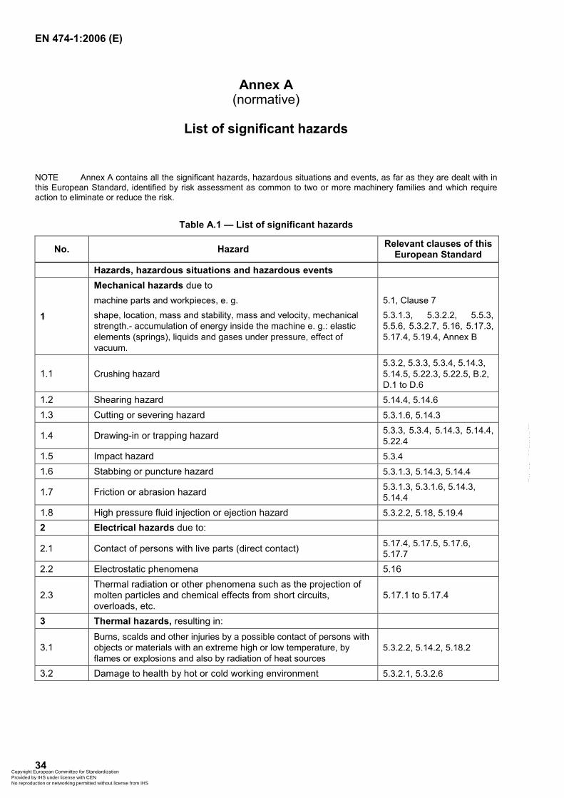
EN 474-1:2006 (E)
34
Annex A (normative)
List of significant hazards
NOTE Annex A contains all the significant hazards, hazardous situations and events, as far as they are dealt with in this European Standard, identified by risk assessment as common to two or more machinery families and which require action to eliminate or reduce the risk.
Table A.1 — List of significant hazards
No. Hazard Relevant clauses of this European Standard
Hazards, hazardous situations and hazardous events
1
Mechanical hazards due to machine parts and workpieces, e. g. shape, location, mass and stability, mass and velocity, mechanical strength.- accumulation of energy inside the machine e. g.: elastic elements (springs), liquids and gases under pressure, effect of vacuum.
5.1, Clause 7 5.3.1.3, 5.3.2.2, 5.5.3, 5.5.6, 5.3.2.7, 5.16, 5.17.3, 5.17.4, 5.19.4, Annex B
1.1 Crushing hazard 5.3.2, 5.3.3, 5.3.4, 5.14.3, 5.14.5, 5.22.3, 5.22.5, B.2, D.1 to D.6
1.2 Shearing hazard 5.14.4, 5.14.6
1.3 Cutting or severing hazard 5.3.1.6, 5.14.3
1.4 Drawing-in or trapping hazard 5.3.3, 5.3.4, 5.14.3, 5.14.4, 5.22.4
1.5 Impact hazard 5.3.4
1.6 Stabbing or puncture hazard 5.3.1.3, 5.14.3, 5.14.4
1.7 Friction or abrasion hazard 5.3.1.3, 5.3.1.6, 5.14.3, 5.14.4
1.8 High pressure fluid injection or ejection hazard 5.3.2.2, 5.18, 5.19.4 2 Electrical hazards due to:
2.1 Contact of persons with live parts (direct contact) 5.17.4, 5.17.5, 5.17.6, 5.17.7
2.2 Electrostatic phenomena 5.16
2.3 Thermal radiation or other phenomena such as the projection of molten particles and chemical effects from short circuits, overloads, etc.
5.17.1 to 5.17.4
3 Thermal hazards, resulting in:
3.1 Burns, scalds and other injuries by a possible contact of persons with objects or materials with an extreme high or low temperature, by flames or explosions and also by radiation of heat sources
5.3.2.2, 5.14.2, 5.18.2
3.2 Damage to health by hot or cold working environment 5.3.2.1, 5.3.2.6
Copyright European Committee for Standardization Provided by IHS under license with CEN
Not for ResaleNo reproduction or networking permitted without license from IHS
--`,,```,,,,````-`-`,,`,,`,`,,`---
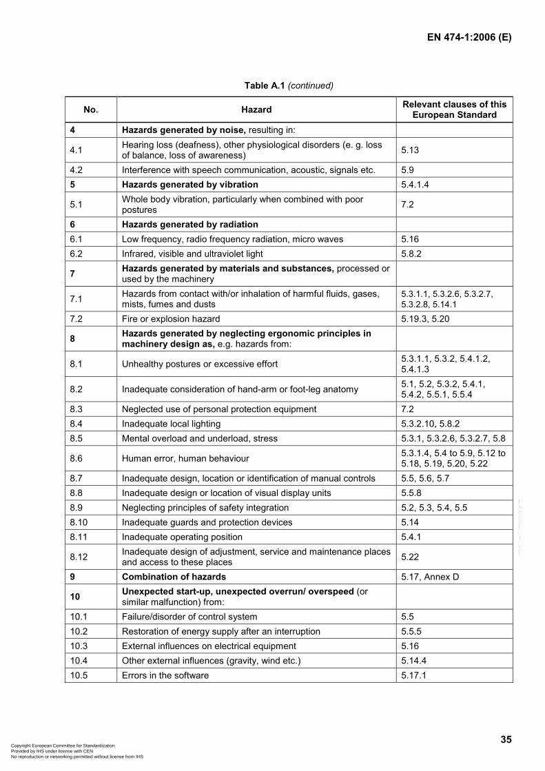
EN 474-1:2006 (E)
35
Table A.1 (continued)
No. Hazard Relevant clauses of this European Standard
4 Hazards generated by noise, resulting in:
4.1 Hearing loss (deafness), other physiological disorders (e. g. loss of balance, loss of awareness) 5.13
4.2 Interference with speech communication, acoustic, signals etc. 5.9 5 Hazards generated by vibration 5.4.1.4
5.1 Whole body vibration, particularly when combined with poor postures 7.2
6 Hazards generated by radiation 6.1 Low frequency, radio frequency radiation, micro waves 5.16 6.2 Infrared, visible and ultraviolet light 5.8.2
7 Hazards generated by materials and substances, processed or used by the machinery
7.1 Hazards from contact with/or inhalation of harmful fluids, gases, mists, fumes and dusts
5.3.1.1, 5.3.2.6, 5.3.2.7, 5.3.2.8, 5.14.1
7.2 Fire or explosion hazard 5.19.3, 5.20
8 Hazards generated by neglecting ergonomic principles in machinery design as, e.g. hazards from:
8.1 Unhealthy postures or excessive effort 5.3.1.1, 5.3.2, 5.4.1.2, 5.4.1.3
8.2 Inadequate consideration of hand-arm or foot-leg anatomy 5.1, 5.2, 5.3.2, 5.4.1, 5.4.2, 5.5.1, 5.5.4
8.3 Neglected use of personal protection equipment 7.2 8.4 Inadequate local lighting 5.3.2.10, 5.8.2 8.5 Mental overload and underload, stress 5.3.1, 5.3.2.6, 5.3.2.7, 5.8
8.6 Human error, human behaviour 5.3.1.4, 5.4 to 5.9, 5.12 to 5.18, 5.19, 5.20, 5.22
8.7 Inadequate design, location or identification of manual controls 5.5, 5.6, 5.7 8.8 Inadequate design or location of visual display units 5.5.8 8.9 Neglecting principles of safety integration 5.2, 5.3, 5.4, 5.5 8.10 Inadequate guards and protection devices 5.14 8.11 Inadequate operating position 5.4.1
8.12 Inadequate design of adjustment, service and maintenance places and access to these places 5.22
9 Combination of hazards 5.17, Annex D
10 Unexpected start-up, unexpected overrun/ overspeed (or similar malfunction) from:
10.1 Failure/disorder of control system 5.5 10.2 Restoration of energy supply after an interruption 5.5.5 10.3 External influences on electrical equipment 5.16 10.4 Other external influences (gravity, wind etc.) 5.14.4 10.5 Errors in the software 5.17.1
Copyright European Committee for Standardization Provided by IHS under license with CEN
Not for ResaleNo reproduction or networking permitted without license from IHS
--`,,```,,,,````-`-`,,`,,`,`,,`---
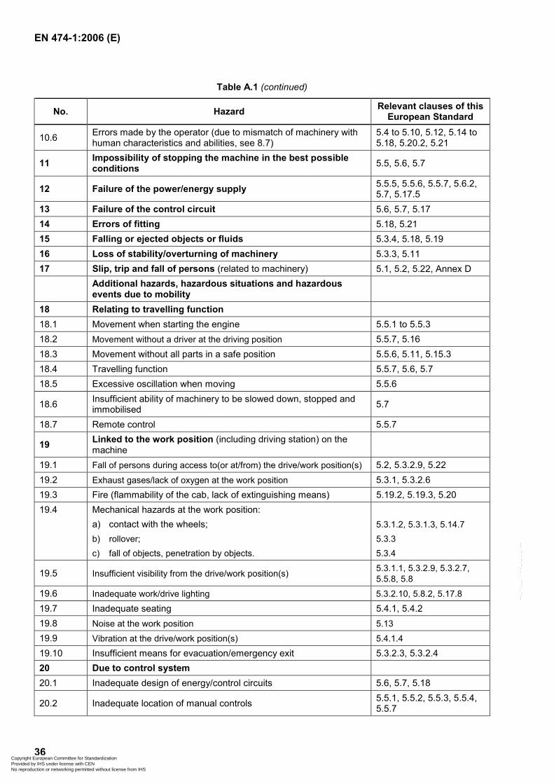
EN 474-1:2006 (E)
36
Table A.1 (continued)
No. Hazard Relevant clauses of this European Standard
10.6 Errors made by the operator (due to mismatch of machinery with human characteristics and abilities, see 8.7)
5.4 to 5.10, 5.12, 5.14 to 5.18, 5.20.2, 5.21
11 Impossibility of stopping the machine in the best possible conditions 5.5, 5.6, 5.7
12 Failure of the power/energy supply 5.5.5, 5.5.6, 5.5.7, 5.6.2, 5.7, 5.17.5
13 Failure of the control circuit 5.6, 5.7, 5.17 14 Errors of fitting 5.18, 5.21 15 Falling or ejected objects or fluids 5.3.4, 5.18, 5.19 16 Loss of stability/overturning of machinery 5.3.3, 5.11 17 Slip, trip and fall of persons (related to machinery) 5.1, 5.2, 5.22, Annex D
Additional hazards, hazardous situations and hazardous events due to mobility
18 Relating to travelling function 18.1 Movement when starting the engine 5.5.1 to 5.5.3 18.2 Movement without a driver at the driving position 5.5.7, 5.16 18.3 Movement without all parts in a safe position 5.5.6, 5.11, 5.15.3 18.4 Travelling function 5.5.7, 5.6, 5.7 18.5 Excessive oscillation when moving 5.5.6
18.6 Insufficient ability of machinery to be slowed down, stopped and immobilised 5.7
18.7 Remote control 5.5.7
19 Linked to the work position (including driving station) on the machine
19.1 Fall of persons during access to(or at/from) the drive/work position(s) 5.2, 5.3.2.9, 5.22 19.2 Exhaust gases/lack of oxygen at the work position 5.3.1, 5.3.2.6 19.3 Fire (flammability of the cab, lack of extinguishing means) 5.19.2, 5.19.3, 5.20 19.4 Mechanical hazards at the work position: a) contact with the wheels; 5.3.1.2, 5.3.1.3, 5.14.7 b) rollover; 5.3.3 c) fall of objects, penetration by objects. 5.3.4
19.5 Insufficient visibility from the drive/work position(s) 5.3.1.1, 5.3.2.9, 5.3.2.7, 5.5.8, 5.8
19.6 Inadequate work/drive lighting 5.3.2.10, 5.8.2, 5.17.8
19.7 Inadequate seating 5.4.1, 5.4.2 19.8 Noise at the work position 5.13
19.9 Vibration at the drive/work position(s) 5.4.1.4
19.10 Insufficient means for evacuation/emergency exit 5.3.2.3, 5.3.2.4 20 Due to control system 20.1 Inadequate design of energy/control circuits 5.6, 5.7, 5.18
20.2 Inadequate location of manual controls 5.5.1, 5.5.2, 5.5.3, 5.5.4, 5.5.7
Copyright European Committee for Standardization Provided by IHS under license with CEN
Not for ResaleNo reproduction or networking permitted without license from IHS
--`,,```,,,,````-`-`,,`,,`,`,,`---
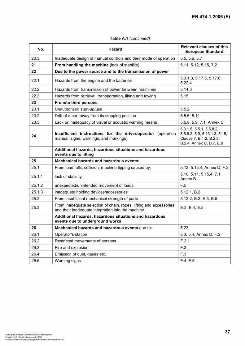
EN 474-1:2006 (E)
37
Table A.1 (continued)
No. Hazard Relevant clauses of this European Standard
20.3 Inadequate design of manual controls and their mode of operation 5.5, 5.6, 5.7 21 From handling the machine (lack of stability) 5.11, 5.12, 5.15, 7.2 22 Due to the power source and to the transmission of power
22.1 Hazards from the engine and the batteries 5.3.1.3, 5.17.5, 5.17.6, 5.22.4
22.2 Hazards from transmission of power between machines 5.14.3 22.3 Hazards from retrieval, transportation, lifting and towing 5.15 23 From/to third persons 23.1 Unauthorised start-up/use 5.5.2 23.2 Drift of a part away from its stopping position 5.5.6, 5.11 23.3 Lack or inadequacy of visual or acoustic warning means 5.5.8, 5.9, 7.1, Annex C
24 Insufficient instructions for the driver/operator (operation manual, signs, warnings, and markings)
5.3.1.5, 5.5.1, 5.5.8.2, 5.5.8.3, 5.9, 5.13.1.3, 5.15, Clause 7, B.1.2, B.2.3, B.2.4, Annex C, D.7, E.6
Additional hazards, hazardous situations and hazardous events due to lifting
25 Mechanical hazards and hazardous events: 25.1 From load falls, collision, machine tipping caused by: 5.12, 5.15.4, Annex D, F.2
25.1.1 lack of stability 5.10, 5.11, 5.15.4, 7.1, Annex B
25.1.2 unexpected/unintended movement of loads F.5 25.1.3 inadequate holding devices/accessories 5.12.1, B.2 25.2 From insufficient mechanical strength of parts 5.12.2, E.2, E.3, E.5
25.3 From inadequate selection of chain, ropes, lifting and accessories and their inadequate integration into the machine E.2, E.4, E.5
Additional hazards, hazardous situations and hazardous events due to underground works
26 Mechanical hazards and hazardous events due to: 5.23 26.1 Operator's station 5.3, 5.4, Annex D, F.2 26.2 Restricted movements of persons F.2.1 26.3 Fire and explosion F.3 26.4 Emission of dust, gases etc. F.3 26.5 Warning signs F.4, F.5
Copyright European Committee for Standardization Provided by IHS under license with CEN
Not for ResaleNo reproduction or networking permitted without license from IHS
--`,,```,,,,````-`-`,,`,,`,`,,`---
EN 474-1:2006 (E)
38
Annex B (normative)
Requirements for attachment and attachment bracket
B.1 Attachment
B.1.1 General
The machine manufacturer shall define the range of attachments intended to be used with the machine and establish the criteria for the safe fitting and use of the attachment.
Requirements for lifting device(s) used for object handling are defined in Annex E.
B.1.2 Identification
The attachment shall be permanently marked with the following information:
manufacturer's name and address;
type denomination (e. g. part No.);
mass, expressed in kilograms (kg);
working circuit pressure, expressed in pascal (Pa), if relevant;
capacity of attachment, e. g. expressed in cubic metres (m3), if relevant.
NOTE Interchangeable equipment should bear CE marking within the EEA.
B.1.3 Instructions
The attachment manufacturer shall provide instructions concerning mounting and use of the attachment.
B.2 Attachment bracket (quick coupling)
B.2.1 Locking
The attachment bracket shall have a locking system that shall meet the following requirements:
the locking system shall keep the attachment bracket in the locked position by a positive engagement system and retain it locked under all intended/normal operating conditions;
it shall be possible to verify the locked position of the attachment bracket from the operator's station, or from the location where the locking control is operated;
it shall not be possible to release the bracket by malfunction or loss of engagement forces.
Wedge-shape locking systems shall provide a continuous force (e. g. continuous pressure with open return, hydraulic accumulator, compressed spring) to hold the attachment in locked position.
Copyright European Committee for Standardization Provided by IHS under license with CEN
Not for ResaleNo reproduction or networking permitted without license from IHS
--`,,```,,,,````-`-`,,`,,`,`,,`---
EN 474-1:2006 (E)
39
B.2.2 Control
For the actuation of a hydraulically operated locking and unlocking system of an attachment bracket, preferably a separate control shall be provided.
The control shall be secured against inadvertent activation (see 5.5.3).
If the actuation is integrated in a control, which is used for other functions than locking/unlocking the attachment bracket, the following requirements shall be met:
activation of the unlocking function shall only be possible by actuation of two independent controls simultaneously (both of the hold-to-run type), or
an acoustical signal shall be in continuous operation for the time of activating the unlocking function. Unlocking of the attachment bracket shall not be possible if the function of the acoustical signal fails by cable rupture. The correct function of this acoustical signal is to be checked at each engine start.
The activated function of those controls (having alternative functions) shall be indicated (see also 5.5.3). In case of a mechanical switch over of the hydraulic circuit (e. g. by a ball valve) it shall be possible to verify the selected operating function from the operator's station. The switch position shall be marked and be clearly identified from the operator's station.
B.2.3 Identification
The markings according to B.1.2 are required for the attachment bracket if they are not permanently integrated into the machine/equipment, except for the marking mentioned in the note.
B.2.4 Instructions
Instructions concerning mounting, locking, checking procedure and the influence on the rated operating/lift /capacity shall be provided by the attachment bracket manufacturer. The checking procedure for locking shall be described in detail and include safety precautions in case of required work-cycle check procedure.
Copyright European Committee for Standardization Provided by IHS under license with CEN
Not for ResaleNo reproduction or networking permitted without license from IHS
--`,,```,,,,````-`-`,,`,,`,`,,`---
EN 474-1:2006 (E)
40
Annex C (informative)
Requirements for no-text safety signs
C.1 General
Safety signs and hazard pictorials should follow the general principles in ISO 9244:1995 and be of general nature understandable and preferably without text. They should be permanently affixed to earth-moving machines and be shown and described in the operation manual. Their location on the machine should be illustrated in the manual.
The warnings on the signs should be indelible and should be legible at the distance necessary to ensure the safety of persons required being in the vicinity.
C.2 Safety alert symbol
The safety alert symbol (see Figure C.1) should be as outlined in ISO 9244:1995, Figure 7. It should be primarily used to warn casual spectators approaching the machine while operating. The safety alert symbol should also be used with hazard description pictorials (see Figures C.3 to C.5).
C.3 Non-text hazard pictorials
Additional hazard pictorials combined with a safety alert symbol (see Figures C.1 to C.5) should be used to warn the operator or service personnel when doing maintenance or service work at the machine. The safety signs should be in two-panel format with either vertical or horizontal figuration (see Figures C.2 to C.4).
C.4 Dimensions
Minimum recommended dimensions for two-panel format safety signs should be according to ISO 9244:1995, Figure 13. Larger or smaller sizes may be used if required.
Safety signs, warning casual spectators approaching the machine while working, should be legible from outside the danger zone.
C.5 Colours of safety signs
The colours of pictorial panels, border and panel separation lines should follow ISO 9244:1995, 9.2.2, 9.2.3, 9.2.4 and 9.5.
C.6 Location
Warning signs and hazard pictorials should be distinctively located at a clearly visible location as close as practical to the hazardous area or part of the machine.
Copyright European Committee for Standardization Provided by IHS under license with CEN
Not for ResaleNo reproduction or networking permitted without license from IHS
--`,,```,,,,````-`-`,,`,,`,`,,`---
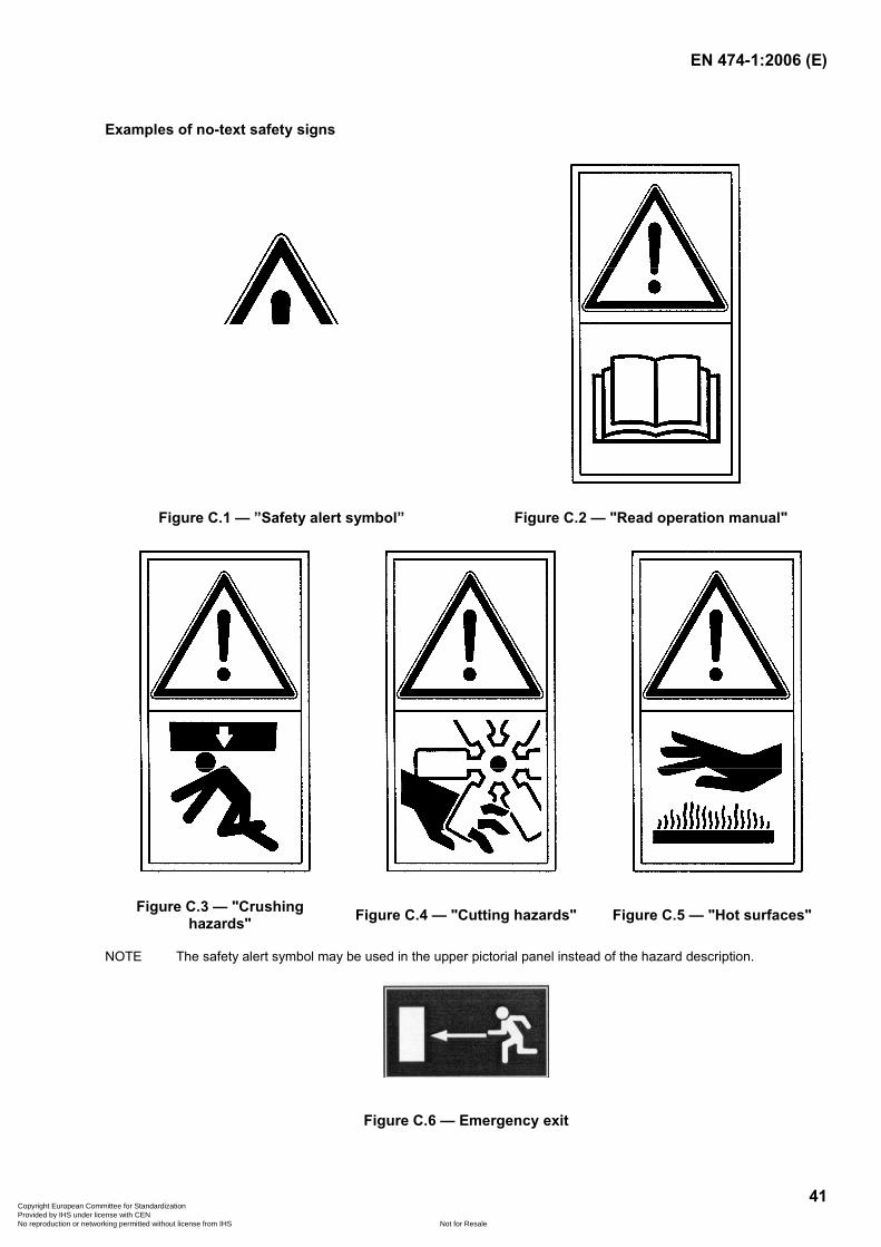
EN 474-1:2006 (E)
41
Examples of no-text safety signs
Figure C.1 — ”Safety alert symbol” Figure C.2 — "Read operation manual"
Figure C.3 — "Crushing hazards" Figure C.4 — "Cutting hazards" Figure C.5 — "Hot surfaces"
NOTE The safety alert symbol may be used in the upper pictorial panel instead of the hazard description.
Figure C.6 — Emergency exit
Copyright European Committee for Standardization Provided by IHS under license with CEN
Not for ResaleNo reproduction or networking permitted without license from IHS
--`,,```,,,,````-`-`,,`,,`,`,,`---
EN 474-1:2006 (E)
42
Annex D (normative)
Requirements for elevating operator's station
D.1 General
Machines with an elevating operator's station, regardless of the elevation height, shall comply with the requirements of 5.3, 5.4 and 5.5. With the station in the lowest position, the access shall comply with 5.2.
The lift and descent speed of the operator’s station shall not exceed 0,6 m/s under normal operating conditions and in case of hydraulic line rupture 0,4 m/s.
If service or maintenance work has to be done with a raised station, a mechanical support device shall be provided. The device shall withstand a force of twice the mass of the operator's station.
D.2 Elevating control
The elevating control shall be clearly marked and protected against unintentional activation.
D.3 Emergency descent
In case of failure of the source of energy, engine stop or hydraulic system failure, it shall be possible for the operator to lower the station to the lowest position (irrespective of the actual position) or to leave the station safely, e. g. by steps or stairs. It shall be possible for a person outside the operator's station to lower the station safely.
The control for the emergency lowering shall be marked red as a safety device.
D.4 Crushing hazards
The hazardous area between the machine main frame and the bottom of the elevated station shall be marked with alternating yellow and black stripes in compliance with ISO 3864-1:2002 and ISO 3864-2:2004 and examples of warning signs according to Annex C. If the operator does not have a direct view of the hazardous area between the station and the frame, e. g. exterior mirror(s) shall be installed to allow the operator to observe the hazardous area when lowering the station.
D.5 Falling down protection for the operator
When the machine is intended for use with the operator's station elevated and with an opened door, and if a falling hazard exists, a seat belt or a protective device (e. g. a bar, chain or strap) shall be provided in the door opening 700 mm above the station floor. The device shall be secured against unintentional opening.
Copyright European Committee for Standardization Provided by IHS under license with CEN
Not for ResaleNo reproduction or networking permitted without license from IHS
--`,,```,,,,````-`-`,,`,,`,`,,`---
EN 474-1:2006 (E)
43
D.6 Roll-over protective structures (ROPS) for elevating station
On machines where a ROPS is required (e. g. trenchers), EN 13510:2000 applies with the following exceptions:
the ROPS for the operator's station shall be regarded as a separate independent ROPS (ROPS not connected to the machine frame);
only the vertical load test of EN 13510:2000, 6.3, shall be applied in all planes;
in the case of symmetrical design of the structure in one or more direction(s): front/rear, left/right, top/bottom, only one test is required in this/these particular direction(s);
EN 13510:2000, 8.8, does not apply.
D.7 Operation manual
The operation manual shall contain safety instructions for elevating stations, e. g.:
the use of seat belts;
station position when travelling;
emergency instructions;
the use of mechanical support device for maintenance.
Copyright European Committee for Standardization Provided by IHS under license with CEN
Not for ResaleNo reproduction or networking permitted without license from IHS
--`,,```,,,,````-`-`,,`,,`,`,,`---
EN 474-1:2006 (E)
44
Annex E (normative)
Requirements for lifting device(s) used for object handling application
E.1 General
This annex specifies requirements for lifting device(s) on earth-moving machines used in object handling operations with regard to strength, assembly and operation.
The tests as defined in this annex may be replaced by calculation.
E.2 Terms, definitions and abbreviations
E.2.1 lifting device(s) device fixed or incorporated to the attachment (working tool) or equipment of the earth-moving machine used for object handling
E.2.2 sling assembly of slinging components, e. g. chain, wire rope or textile material (see EN 1492-1:2000 and EN 1492-2:2002), joined to upper or lower terminals suitable for attaching loads to the lifting point
E.2.3 rated lifting load (RLL) maximum mass for which the lifting device(s) are designed
NOTE The rated lifting load (RLL) can be different from the rated operating/lift capacity of the machine.
E.2.4 attachable hook component intended to be fixed to the attachment (working tool) or the equipment of the earth-moving machine either welded or bolted
E.3 Safety requirements
E.3.1 Mounting and fixing
The lifting device(s) shall be so positioned on the attachment or the other parts of the earth-moving machine that an unintentional unhooking of the sling is avoided. (For test see E.4.2.)
The location at the attachment or the equipment shall provide best visibility between the operator and the striker [operator to attach the sling to the lifting device(s)].
The fixing position of the lifting device(s) shall avoid that the sling is deflected from its vertical load by other machine parts, except when the sling is guided over the back-wall of the bucket (see Figure F.1) or over the rounded shape of sufficient diameter.
Copyright European Committee for Standardization Provided by IHS under license with CEN
Not for ResaleNo reproduction or networking permitted without license from IHS
--`,,```,,,,````-`-`,,`,,`,`,,`---
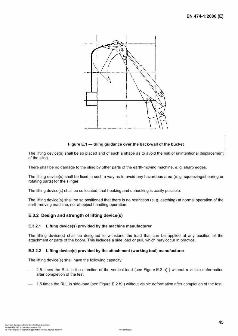
EN 474-1:2006 (E)
45
Figure E.1 — Sling guidance over the back-wall of the bucket
The lifting device(s) shall be so placed and of such a shape as to avoid the risk of unintentional displacement of the sling.
There shall be no damage to the sling by other parts of the earth-moving machine, e. g. sharp edges.
The lifting device(s) shall be fixed in such a way as to avoid any hazardous area (e. g. squeezing/shearing or rotating parts) for the slinger.
The lifting device(s) shall be so located, that hooking and unhooking is easily possible.
The lifting device(s) shall be so positioned that there is no restriction (e. g. catching) at normal operation of the earth-moving machine, nor at object handling operation.
E.3.2 Design and strength of lifting device(s)
E.3.2.1 Lifting device(s) provided by the machine manufacturer
The lifting device(s) shall be designed to withstand the load that can be applied at any position of the attachment or parts of the boom. This includes a side load or pull, which may occur in practice.
E.3.2.2 Lifting device(s) provided by the attachment (working tool) manufacturer
The lifting device(s) shall have the following capacity:
2,5 times the RLL in the direction of the vertical load (see Figure E.2 a) ) without a visible deformation after completion of the test;
1,5 times the RLL in side-load (see Figure E.2 b) ) without visible deformation after completion of the test.
Copyright European Committee for Standardization Provided by IHS under license with CEN
Not for ResaleNo reproduction or networking permitted without license from IHS
--`,,```,,,,````-`-`,,`,,`,`,,`---
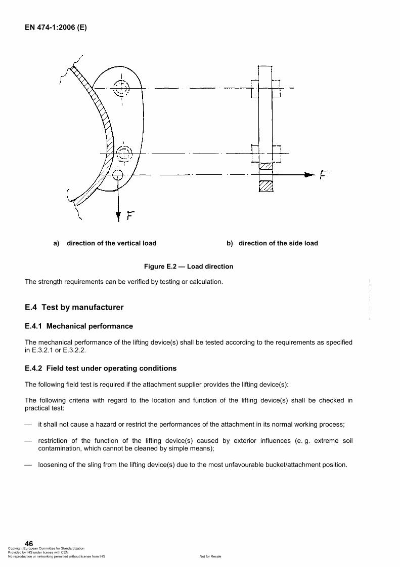
EN 474-1:2006 (E)
46
a) direction of the vertical load b) direction of the side load
Figure E.2 — Load direction
The strength requirements can be verified by testing or calculation.
E.4 Test by manufacturer
E.4.1 Mechanical performance
The mechanical performance of the lifting device(s) shall be tested according to the requirements as specified in E.3.2.1 or E.3.2.2.
E.4.2 Field test under operating conditions
The following field test is required if the attachment supplier provides the lifting device(s):
The following criteria with regard to the location and function of the lifting device(s) shall be checked in practical test:
it shall not cause a hazard or restrict the performances of the attachment in its normal working process;
restriction of the function of the lifting device(s) caused by exterior influences (e. g. extreme soil contamination, which cannot be cleaned by simple means);
loosening of the sling from the lifting device(s) due to the most unfavourable bucket/attachment position.
Copyright European Committee for Standardization Provided by IHS under license with CEN
Not for ResaleNo reproduction or networking permitted without license from IHS
--`,,```,,,,````-`-`,,`,,`,`,,`---
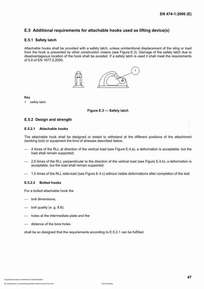
EN 474-1:2006 (E)
47
E.5 Additional requirements for attachable hooks used as lifting device(s)
E.5.1 Safety latch
Attachable hooks shall be provided with a safety latch, unless unintentional displacement of the sling or load from the hook is prevented by other construction means (see Figure E.3). Damage of the safety latch due to disadvantageous location of the hook shall be avoided. If a safety latch is used it shall meet the requirements of 5.6 of EN 1677-2:2000.
Key 1 safety latch
Figure E.3 — Safety latch
E.5.2 Design and strength
E.5.2.1 Attachable hooks
The attachable hook shall be designed or tested to withstand at the different positions of the attachment (working tool) or equipment the kind of stresses described below:
4 times of the RLL at direction of the vertical load (see Figure E.4.a), a deformation is acceptable, but the load shall remain supported;
2,5 times of the RLL perpendicular to the direction of the vertical load (see Figure E.4.b), a deformation is acceptable, but the load shall remain supported;
1,5 times of the RLL side-load (see Figure E.4.c) without visible deformations after completion of the test.
E.5.2.2 Bolted hooks
For a bolted attachable hook the
bolt dimensions;
bolt quality (e. g. 8.8);
holes at the intermediate plate and the
distance of the bore holes
shall be so designed that the requirements according to E.5.2.1 can be fulfilled.
Copyright European Committee for Standardization Provided by IHS under license with CEN
Not for ResaleNo reproduction or networking permitted without license from IHS
--`,,```,,,,````-`-`,,`,,`,`,,`---
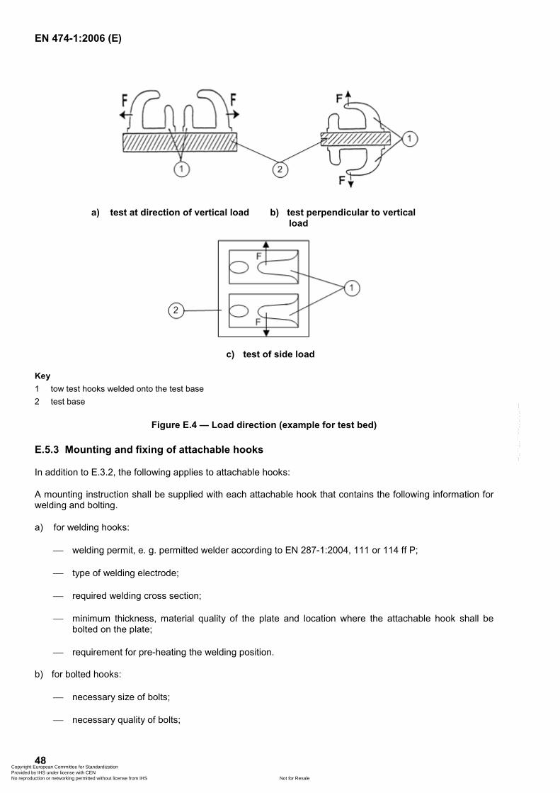
EN 474-1:2006 (E)
48
a) test at direction of vertical load b) test perpendicular to vertical load
c) test of side load
Key 1 tow test hooks welded onto the test base 2 test base
Figure E.4 — Load direction (example for test bed)
E.5.3 Mounting and fixing of attachable hooks
In addition to E.3.2, the following applies to attachable hooks:
A mounting instruction shall be supplied with each attachable hook that contains the following information for welding and bolting.
a) for welding hooks:
welding permit, e. g. permitted welder according to EN 287-1:2004, 111 or 114 ff P;
type of welding electrode;
required welding cross section;
minimum thickness, material quality of the plate and location where the attachable hook shall be bolted on the plate;
requirement for pre-heating the welding position.
b) for bolted hooks:
necessary size of bolts;
necessary quality of bolts;
Copyright European Committee for Standardization Provided by IHS under license with CEN
Not for ResaleNo reproduction or networking permitted without license from IHS
--`,,```,,,,````-`-`,,`,,`,`,,`---
EN 474-1:2006 (E)
49
necessary tightening torque;
minimum thickness, material quality of the plate and location where the attachable hook shall be bolted on the plate.
E.5.4 Mechanical performance test
E.5.4.1 General
In addition to E.4, the tests specified in E.5.4.2 and E.5.4.3 shall be made.
E.5.4.2 Mechanical performance
A minimum of three samples shall be tested and shall fulfil the requirements of E.5.2.
E.5.4.3 Field tests
The field test according to E.4.2 applies also to attachable hooks. In addition, possible damages of the safety latch due to the most unfavourable attachment (working tool) or equipment position shall be checked.
E.5.4.4 Verification
The results of the tests shall be noted in test certificate with the date of issue and who has carried out the tests.
E.5.5 Identification
The lifting device(s) shall be permanently marked with a means of identification and the rated lifting load RLL according to E.2.3.
E.6 Operation manual
An operation manual shall be supplied by the manufacturer of the lifting device(s) and shall include the following information for use of the lifting device(s):
the intended use of the lifting device(s);
the safe hooking of the load;
the visual inspection;
a recommendation for a periodical inspection of the lifting device(s).
In addition, if the manufacturer of the lifting device(s) is not the manufacturer of the machine, the operation manual shall include:
information regarding the correct size of the lifting device(s) used on the respective machine range and its equipment and attachment;
instructions for mounting and fixing (see E.3.1 and E.5.3 if necessary);
instructions for performing the field test (see E.4.2 and E.5.4.3, if necessary) by the user.
Copyright European Committee for Standardization Provided by IHS under license with CEN
Not for ResaleNo reproduction or networking permitted without license from IHS
--`,,```,,,,````-`-`,,`,,`,`,,`---
EN 474-1:2006 (E)
50
Annex F (normative)
Requirements for earth-moving machinery used in underground working
in non-explosive atmosphere
F.1 General
This annex gives additional requirements and exceptions for earth-moving machinery intended to be exclusively used in underground working in non-explosive atmosphere.
NOTE 1 Examples of underground working are underground mining and tunnelling.
NOTE 2 For additional requirements for earth-moving machinery used underground in potentially explosive atmospheres, see EN 1710:2005.
NOTE 3 Finishing or maintenance work in open tunnels is not regarded as underground work according to this European Standard.
F.2 Operator's station
F.2.1 Operator's station with cab
Earth-moving machines used in underground working shall be equipped with a cab in accordance with 5.3.
F.2.2 Operator's station with reduced dimension of the cab
F.2.2.1 Exception to F.2.1
The following exceptions to F.2.1 stated in F.2.2.2 to F.2.2.5 can be accepted if the machine is intended to be used for underground working site not permitting full cab height.
F.2.2.2 Space envelope
The space envelope height of machines with cab can be reduced, but shall not be less than 900 mm above SIP.
F.2.2.3 Transmitted vibration
The seat shall comply with EN ISO 7096:2000. If for technical reasons this is not possible, seat of input spectral class EM 8 may be used.
F.2.2.4 Seat
If 5.4.1.3 cannot be met for space reasons, vertical adjustment according to ISO 11112:1995, Table 1, h1, is not required.
F.2.2.5 Alternative opening (emergency exit)
An alternative opening shall be provided. The rectangular dimension shall be not less than 470 mm ✕ 600 mm.
Copyright European Committee for Standardization Provided by IHS under license with CEN
Not for ResaleNo reproduction or networking permitted without license from IHS
--`,,```,,,,````-`-`,,`,,`,`,,`---
EN 474-1:2006 (E)
51
F.2.3 Operator's station without cab
If hazards such as roll over, falling objects or dust, noise, high temperature are not significant, machines may be used without cab.
F.3 Engine exhaust emission and fuel
F.3.1 Engine and fuel
Only engines with low exhaust emission values, using the best technology available to reduce exposure to exhaust emissions, adapted to the work site in question, shall be used.
If internal combustion engines are used, they shall be of diesel type.
The fuel shall not have a flash point below 55°C.
NOTE Internal combustion engines should be type-approved within the EEA countries.
F.3.2 Fuel system
In case of failure in the fuel line between the fuel tank and the engine, an easily accessible device shall be fitted to block the fuel line as close as possible to the tank to prevent leakage.
F.4 Lighting, signalling and marking lights and reflex-reflector devices
F.4.1 General
5.8.2 applies with the exceptions specified in F.4.2 to F.4.4.
F.4.2 Light assembly position
The assembly position as specified in ISO 12509:2004 may be adapted to the application in underground working.
F.4.3 Rear position lamp
5.8.2 applies with the following addition:
ISO 12509:1995, E.10, applies also for machines, category I A, I B and III B.
F.4.4 Machines working in both directions in work cycle
Where a machine is capable of operation in both directions (forward/reverse) in the work cycle, the lighting shall be arranged with special warning light and duplication of work lamp, and to the front and rear, duplication of rear position lamp (red/white). This function shall automatically be changed to the corresponding gear.
Copyright European Committee for Standardization Provided by IHS under license with CEN
Not for ResaleNo reproduction or networking permitted without license from IHS
--`,,```,,,,````-`-`,,`,,`,`,,`---
EN 474-1:2006 (E)
52
Annex ZA (informative)
Relationship between this European Standard and the Essential
Requirements of EU Directive 98/37/EC
This European Standard has been prepared under a mandate given to CEN by the European Commission and the European Free Trade Association to provide a means of conforming to Essential Requirements of the New Approach Directive Machinery 98/37/EC, amended by 98/79/EC.
Once this standard is cited in the Official Journal of the European Communities under that Directive and has been implemented as a national standard in at least one Member State, compliance with the normative clauses of this standard confers, within the limits of the scope of this standard, a presumption of conformity with the relevant Essential Requirements of that Directive and associated EFTA regulations.
WARNING — Other requirements and other EU Directives may be applicable to the product(s) falling within the scope of this standard.
Copyright European Committee for Standardization Provided by IHS under license with CEN
Not for ResaleNo reproduction or networking permitted without license from IHS
--`,,```,,,,````-`-`,,`,,`,`,,`---

EN 474-1:2006 (E)
53
Bibliography
EC Directives
[1] 67/548/EEC, Article (2) of Council Directive 67/548/EEC of 27 June 1967 on the approximation of laws, regulations and administrative provisions relating to classification, packaging and labelling of dangerous substances
[2] 73/23/EEC, Council Directive of 19 February 1973 on the harmonization of the laws of Member States relating to electrical equipment designed for use within certain voltage limits
[3] 87/404/EEC, Council Directive of 25 June 1987, on the harmonisation of the laws of the Member States relating to simple pressure vessels and its amendments
[4] 89/336/EEC, Council Directive of 3 May 1989 on the approximation of the laws of the Member States relating to electromagnetic compatibility and its amendments
[5] 92/58/EEC, Council Directive of 24 June 1992 on the approximation of the laws, regulations and administrative provisions of the Member States relating to safety signs at places of work
[6] 94/9/EC, Directive of the European Parliament and of the Council of 23 March 1994 approximation of the laws of the Member States concerning equipment and protective systems intended for use in potentially explosive atmospheres
[7] 97/23/EC, Directive of the European Parliament and of the Council of 29 May 1997 on the approximation of the laws of the Member States concerning pressure equipment
[8] 97/68/EC, Directive of the European Parliament and of the Council of 16 December 1997 on the approximation of the laws of the Member States relating to measures against the emission of gaseous and particulate pollutants from internal combustion engines to be installed in non-road mobile machinery
[9] 98/37/EC, Council Directive of 22 June 1998 on the approximation of the law of the Member States relating to machinery (Machinery Safety Directive) and its amendment 98/79 EC
[10] 2000/14/EC. Directive of the European Parliament and of the Council of 8 May 2000 on the approximation of laws of the Members relating to the noise emission in the environmental by equipment for use outdoors
[11] Position paper on guidelines for the application of the European Parliament and Council Directive 2000/14/EC on the approximation of the laws of the Member States relating to the noise emission in the environment by equipment for use outdoors
[12] Common position (EC) No 20/97 adopted by the Council on the 17 April 1997 with a view to adopting Decision No. 1971/EC of the European Community programme of policy and action in relation to the environment and sustainable development "Towards sustainability"
ECE Regulations
[13] United Nations – Agreement concerning the adoption of uniform conditions of approval and reciprocal recognition of approval for motor vehicle equipment and parts. (Economic Commission of Europe)
[14] ECE R34, Uniform provisions concerning the approval of vehicles with regard to the prevention of fire risks
Copyright European Committee for Standardization Provided by IHS under license with CEN
Not for ResaleNo reproduction or networking permitted without license from IHS
--`,,```,,,,````-`-`,,`,,`,`,,`---
EN 474-1:2006 (E)
54
[15] ECE R43, Annex 5, Uniform provisions concerning the approval of safety glazing and glazing material. Uniformly-Toughened Glass Panes
[16] ECE R46, Uniform provisions concerning the approval of rear-view mirrors, and of motor vehicles with regard to the installation of rear-view-mirrors
Standards
[17] EN 294:1992, Safety of machinery — Safety distances to prevent danger zones being reached by the upper limbs
[18] EN 500 (all parts), Mobile road construction machinery
[19] EN 1492-1:2000, Textile slings — Safety — Part 1: Flat woven webbing slings, made of man-made fibres, for general purpose use
[20] EN 1492-2:2000, Textile slings — Safety — Part 2: Roundslings, made of man-made fibres, for general purpose use
[21] EN 1710:2005, Equipment and components intended for use in potentially explosive atmospheres in underground mines
[22] EN ISO 11688-1:1998, Acoustics — Recommended practice for the design of low-noise machinery and equipment — Part 1: Planning (ISO/TR 11688-1:1995)
[23] EN ISO 11688-2:2000, Acoustics — Recommended practice for the design of low-noise machinery and equipment — Part 2: Introduction to the physics of low-noise design (ISO/TR 11688-2:1998)
[24] EN ISO 15667:2000, Acoustics — Guidelines for noise control by enclosures and cabins (ISO 15667:2000)
[25] ISO 19472:2006, Machinery for forestry -- Winches -- Dimensions, performance and safety
[26] ISO 6750:2005, Earth-moving machinery — Operator’s manual -— Content and format
[27] ISO 6746-1:2003, Earth-moving machinery — Definitions of dimensions and codes — Part 1: Base machine
[28] ISO 6746-2:2003, Earth-moving machinery — Definitions of dimensions and codes — Part 2: Equipment and attachments
[29] ISO 8084:2003, Machinery for forestry — Operator protective structures — Laboratory tests and performance requirements
[30] ISO 9244:1955, .Earth-moving machinery – Safety signs and hazard pictorials – General principles
[31] ISO 9247:1990, Earth-moving machinery — Electrical wires and cables — Principles of identification and marking
[32] ISO 10261:2002, Earth-moving machinery — Product identification numbering system
[33] ISO 10263-4:1994, Earth-moving machinery — Operator enclosure environment — Part 4: Operator enclosure ventilation, heating and/or air-conditioning test method
[34] ISO 10263-5:1994, Earth-moving machinery — Operator enclosure environment — Part 5: Windscreen defrosting system test method
Copyright European Committee for Standardization Provided by IHS under license with CEN
Not for ResaleNo reproduction or networking permitted without license from IHS
--`,,```,,,,````-`-`,,`,,`,`,,`---

blankCopyright European Committee for Standardization Provided by IHS under license with CEN
Not for ResaleNo reproduction or networking permitted without license from IHS
--`,,```,,,,````-`-`,,`,,`,`,,`---
CopProNo
BS EN 474-1:2006
vr
--`,,```,,,,````-`-`,,`,,`,`,,`---
BSI389 Chiswick High RoadLondonW4 4AL
yright European Committee for Standardization ided by IHS under license with CENeproduction or networking permitted without license from IHS
BSI — British Standards InstitutionBSI is the independent national body responsible for preparing British Standards. It presents the UK view on standards in Europe and at the international level. It is incorporated by Royal Charter.
Revisions
British Standards are updated by amendment or revision. Users of British Standards should make sure that they possess the latest amendments or editions.
It is the constant aim of BSI to improve the quality of our products and services. We would be grateful if anyone finding an inaccuracy or ambiguity while using this British Standard would inform the Secretary of the technical committee responsible, the identity of which can be found on the inside front cover. Tel: +44 (0)20 8996 9000. Fax: +44 (0)20 8996 7400.
BSI offers members an individual updating service called PLUS which ensures that subscribers automatically receive the latest editions of standards.
Buying standards
Orders for all BSI, international and foreign standards publications should be addressed to Customer Services. Tel: +44 (0)20 8996 9001. Fax: +44 (0)20 8996 7001. Email: [email protected]. Standards are also available from the BSI website at http://www.bsi-global.com.
In response to orders for international standards, it is BSI policy to supply the BSI implementation of those that have been published as British Standards, unless otherwise requested.
Information on standards
BSI provides a wide range of information on national, European and international standards through its Library and its Technical Help to Exporters Service. Various BSI electronic information services are also available which give details on all its products and services. Contact the Information Centre. Tel: +44 (0)20 8996 7111. Fax: +44 (0)20 8996 7048. Email: [email protected].
Subscribing members of BSI are kept up to date with standards developments and receive substantial discounts on the purchase price of standards. For details of these and other benefits contact Membership Administration. Tel: +44 (0)20 8996 7002. Fax: +44 (0)20 8996 7001. Email: [email protected].
Information regarding online access to British Standards via British Standards Online can be found at http://www.bsi-global.com/bsonline.
Further information about BSI is available on the BSI website at http://www.bsi-global.com.
Copyright
Copyright subsists in all BSI publications. BSI also holds the copyright, in the UK, of the publications of the international standardization bodies. Except as permitted under the Copyright, Designs and Patents Act 1988 no extract may be reproduced, stored in a retrieval system or transmitted in any form or by any means – electronic, photocopying, recording or otherwise – without prior written permission from BSI.
This does not preclude the free use, in the course of implementing the standard, of necessary details such as symbols, and size, type or grade designations. If these details are to be used for any other purpose than implementation then the prior written permission of BSI must be obtained.
Details and advice can be obtained from the Copyright & Licensing Manager. Tel: +44 (0)20 8996 7070. Fax: +44 (0)20 8996 7553. Email: [email protected].
Not for Resale