Embed Size (px)
Citation preview
ECE 451 – Jose Schutt‐Aine 1
ECE 451Advanced Microwave Measurements
Error Correction
Jose E. Schutt-AineElectrical & Computer Engineering
University of [email protected]
ECE 451 – Jose Schutt‐Aine 2
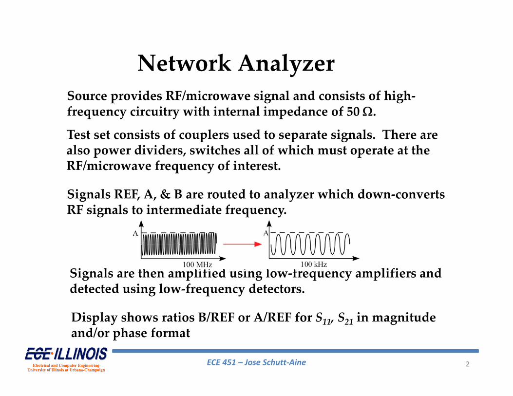
Source provides RF/microwave signal and consists of high‐frequency circuitry with internal impedance of 50 .
Test set consists of couplers used to separate signals. There are also power dividers, switches all of which must operate at the RF/microwave frequency of interest.
Signals REF, A, & B are routed to analyzer which down‐converts RF signals to intermediate frequency.
Signals are then amplified using low‐frequency amplifiers and detected using low‐frequency detectors.
Display shows ratios B/REF or A/REF for S11, S21 in magnitude and/or phase format
Network Analyzer
ECE 451 – Jose Schutt‐Aine 3
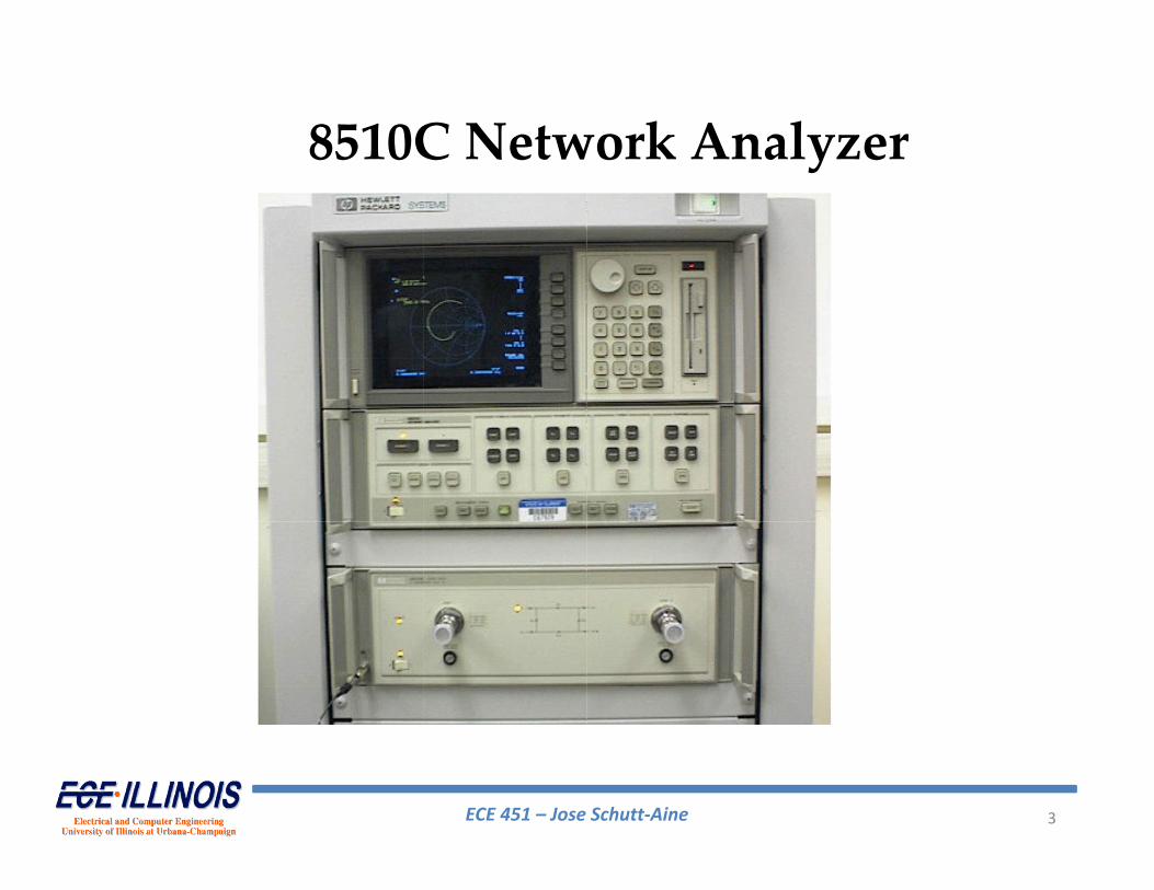
8510C Network Analyzer
ECE 451 – Jose Schutt‐Aine 4
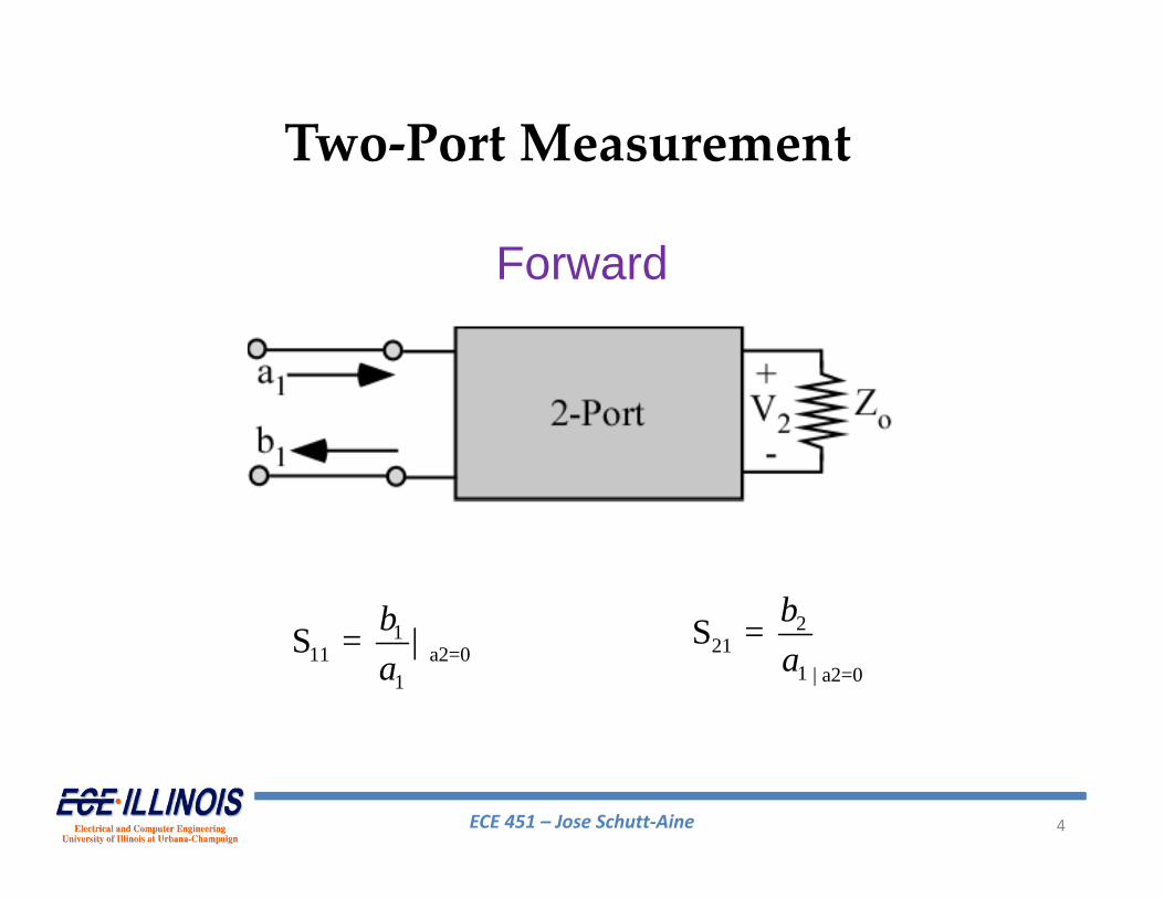
111 a2=0
1
S = | ba
221
1 | a2=0
S = ba
Two‐Port Measurement
Forward
ECE 451 – Jose Schutt‐Aine 5
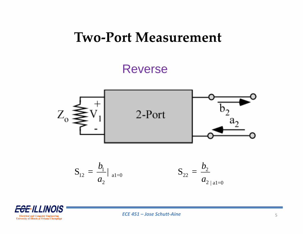
Two‐Port Measurement
Reverse
112 a1=0
2
S = | ba
222
2 | a1=0
S = ba
ECE 451 – Jose Schutt‐Aine 6
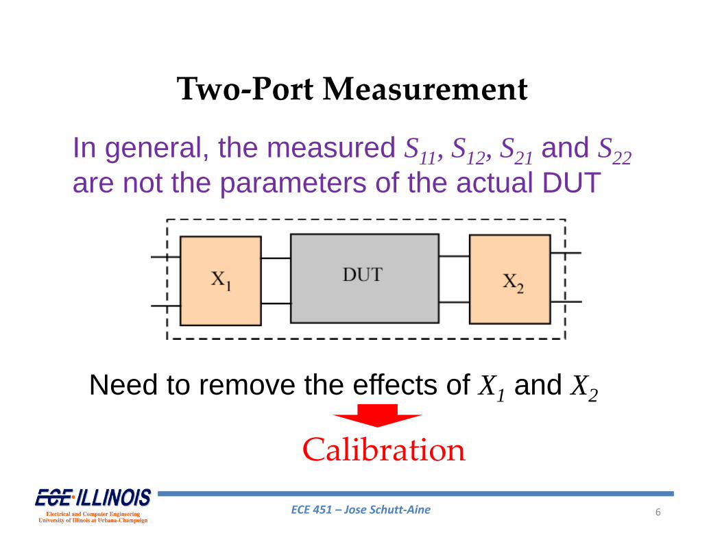
Two‐Port Measurement
In general, the measured S11, S12, S21 and S22are not the parameters of the actual DUT
Need to remove the effects of X1 and X2
Calibration
ECE 451 – Jose Schutt‐Aine 7
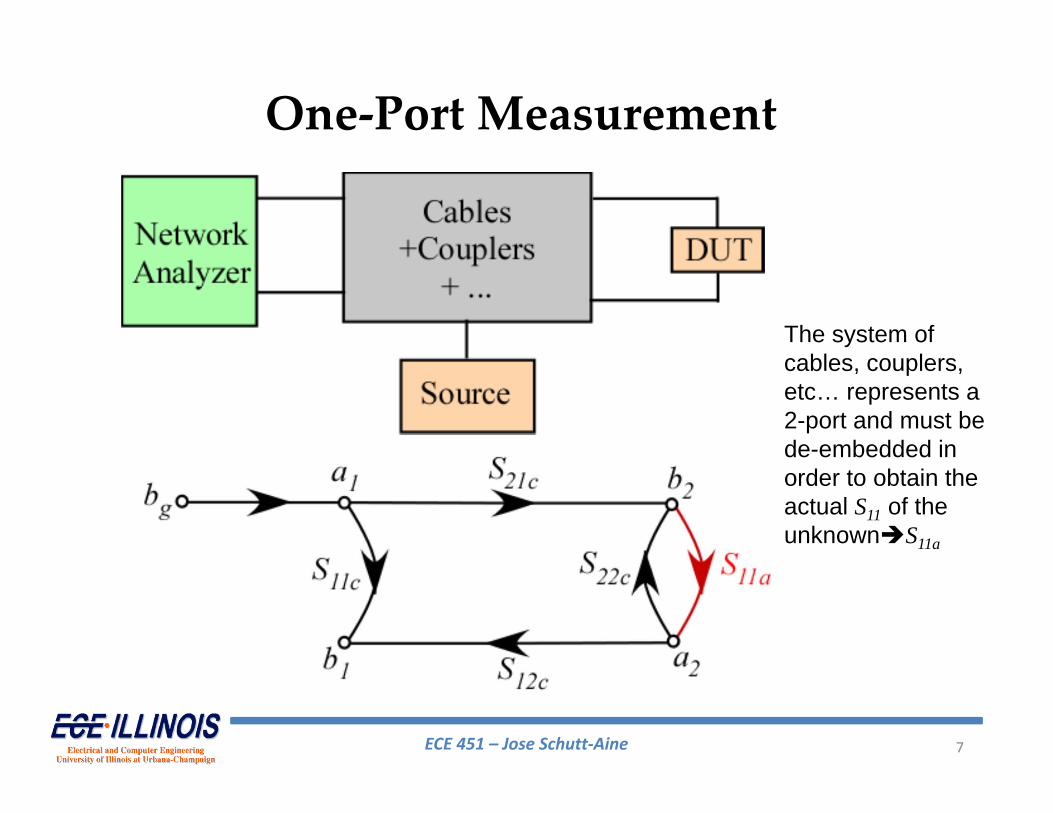
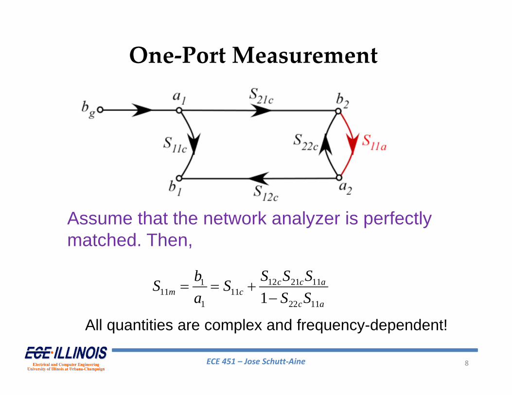
One‐Port Measurement
The system of cables, couplers, etc… represents a 2-port and must be de-embedded in order to obtain the actual S11 of the unknownS11a
ECE 451 – Jose Schutt‐Aine 8
Assume that the network analyzer is perfectly matched. Then,
12 21 11111 11
1 22 111c c a
m cc a
S S SbS Sa S S
One‐Port Measurement
All quantities are complex and frequency-dependent!
ECE 451 – Jose Schutt‐Aine 9
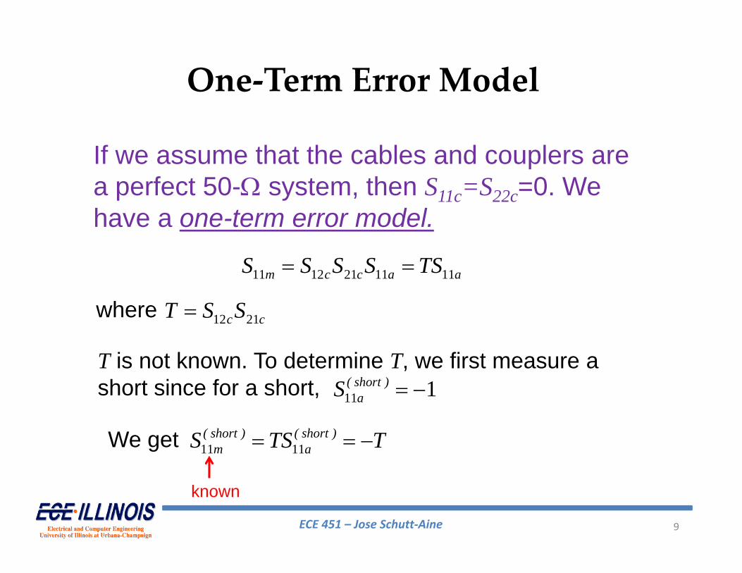
One‐Term Error Model
If we assume that the cables and couplers are a perfect 50- system, then S11c=S22c=0. We have a one-term error model.
11 12 21 11 11m c c a aS S S S TS
where 12 21c cT S S
T is not known. To determine T, we first measure a short since for a short, 11 1( short )
aS
We get 11 11( short ) ( short )
m aS TS T
known
ECE 451 – Jose Schutt‐Aine 10
One‐Term Error Model
1111
11
( DUT )m( DUT )
a ( short )m
SS
S
From which11 11
1111
( DUT ) ( DUT )( DUT ) m m
a ( short )m
S SST S
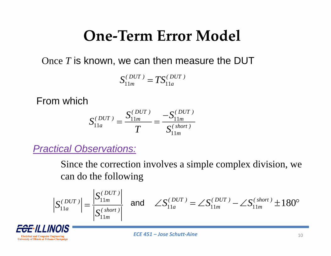
Once T is known, we can then measure the DUT
11 11( DUT ) ( DUT )
m aS TS
Practical Observations:Since the correction involves a simple complex division, we can do the following
11 11 11 180( DUT ) ( DUT ) ( short )a m mS S S and
ECE 451 – Jose Schutt‐Aine 11
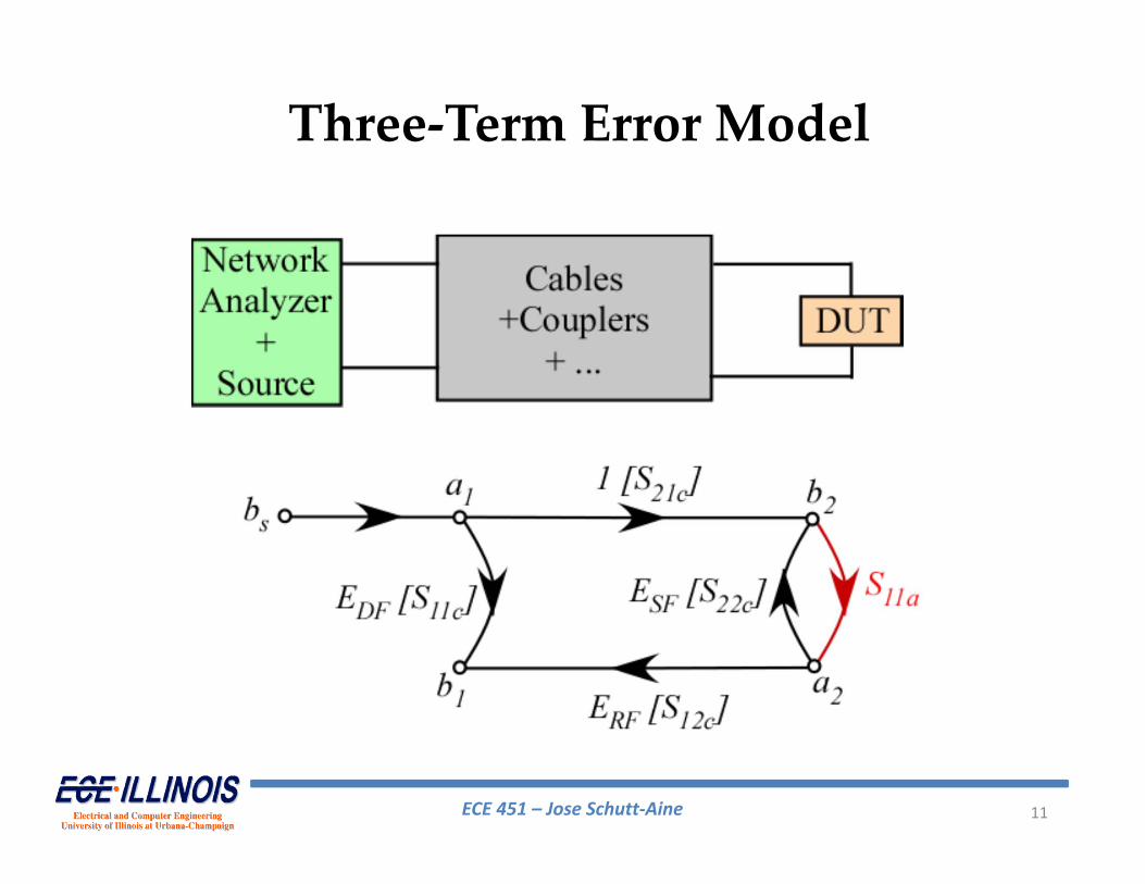
Three‐Term Error Model
ECE 451 – Jose Schutt‐Aine 12
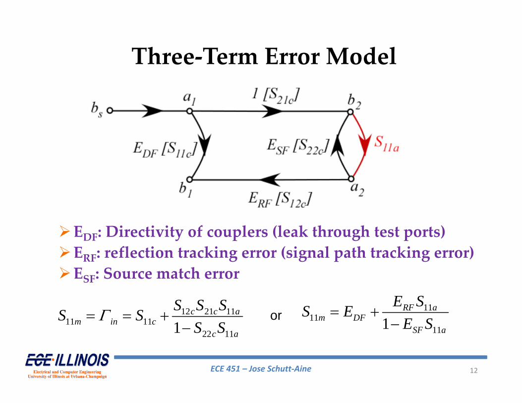
EDF: Directivity of couplers (leak through test ports)ERF: reflection tracking error (signal path tracking error)ESF: Source match error
Three‐Term Error Model
12 21 1111 11
22 111c c a
m in cc a
S S SS SS S
1111
111RF a
m DFSF a
E SS EE S
or
ECE 451 – Jose Schutt‐Aine 13
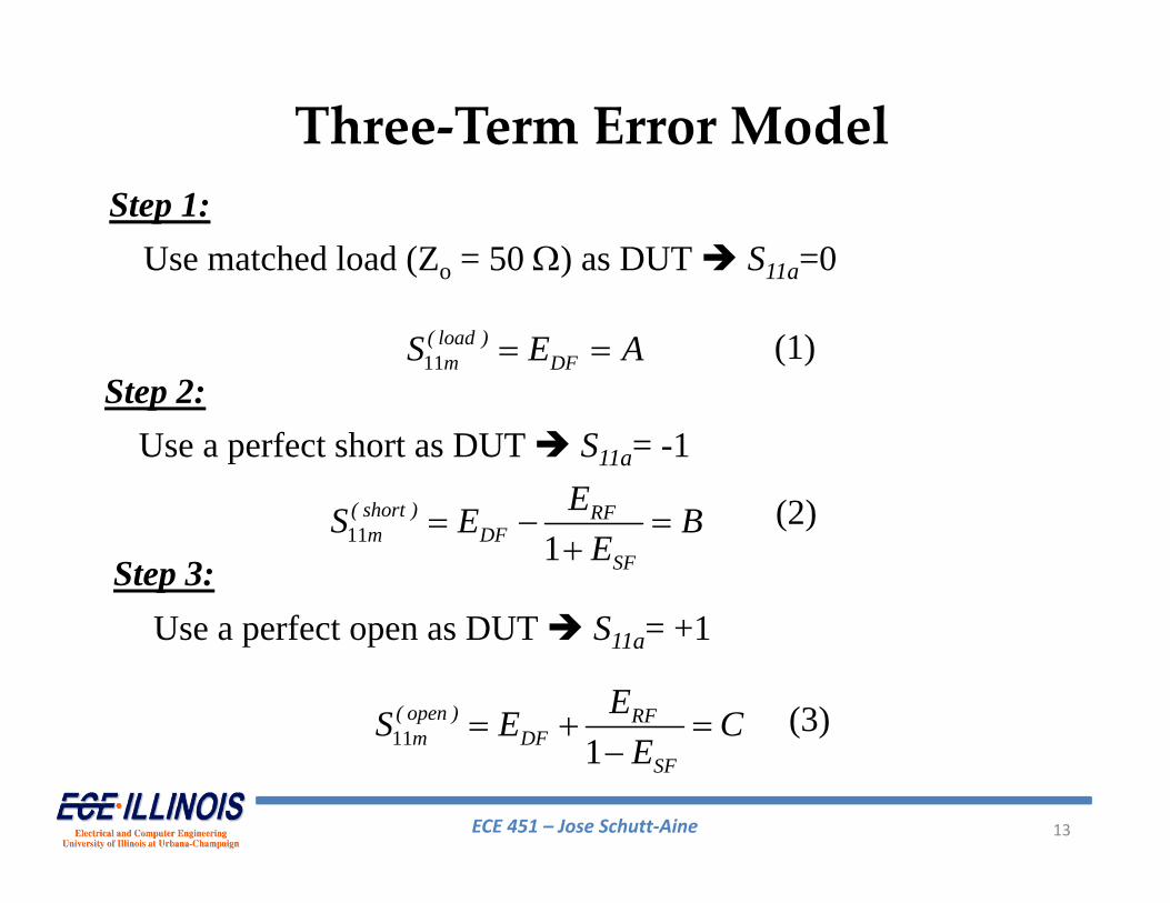
Three‐Term Error ModelStep 1:
Use matched load (Zo = 50 ) as DUT S11a=0
11( load )
m DFS E A Step 2:
Use a perfect short as DUT S11a= -1
11 1( short ) RF
m DFSF
ES E BE
Step 3:Use a perfect open as DUT S11a= +1
11 1( open ) RF
m DFSF
ES E CE
(1)
(2)
(3)
ECE 451 – Jose Schutt‐Aine 14
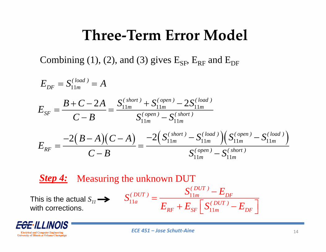
Three‐Term Error ModelCombining (1), (2), and (3) gives ESF, ERF and EDF
11( load )
DF mE S A
11 11 11
11 11
22 ( short ) ( open ) ( load )m m m
SF ( open ) ( short )m m
S S SB C AEC B S S
Step 4:
11 11 11 11
11 11
22 ( short ) ( load ) ( open ) ( load )m m m m
RF ( open ) ( short )m m
S S S SB A C AE
C B S S
Measuring the unknown DUT11
1111
( DUT )( DUT ) m DF
a ( DUT )RF SF m DF
S ESE E S E
This is the actual S11with corrections.

ECE 451 – Jose Schutt‐Aine 15
Alternative Calibration StandardsAt very high frequencies, it is difficult to make a good short, open or matched termination. We need to find alternative standards for calibration.
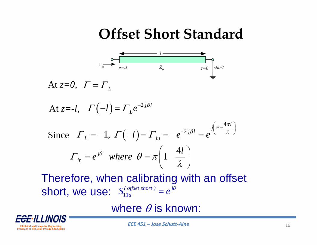
Offset Short
TL of length l terminated with a short
ECE 451 – Jose Schutt‐Aine 16
Offset Short Standard
At z=0, L
At z=-l, 2 j lLl e
Since 4
21lj
j lL in, l e e
41jin
le where
Therefore, when calibrating with an offset short, we use: 11
( offset short ) jaS e
where is known:
ECE 451 – Jose Schutt‐Aine 17
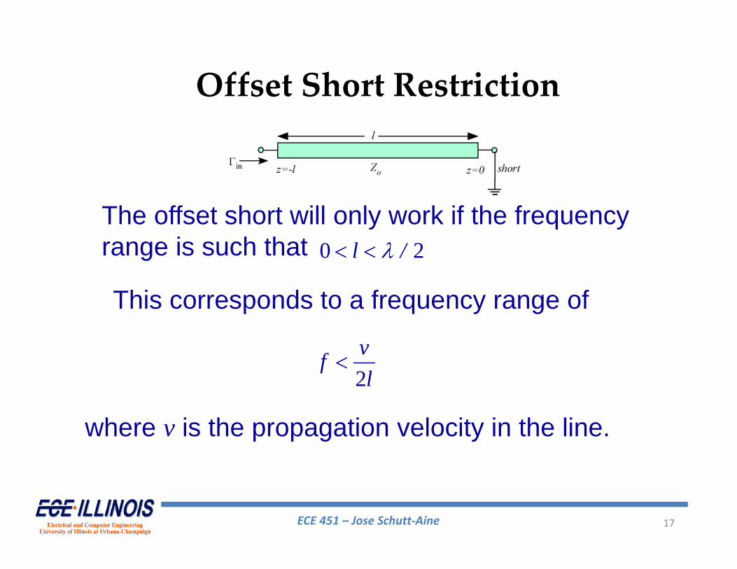
Offset Short Restriction
The offset short will only work if the frequency range is such that
where v is the propagation velocity in the line.
0 2l /
This corresponds to a frequency range of
2vfl
ECE 451 – Jose Schutt‐Aine 18
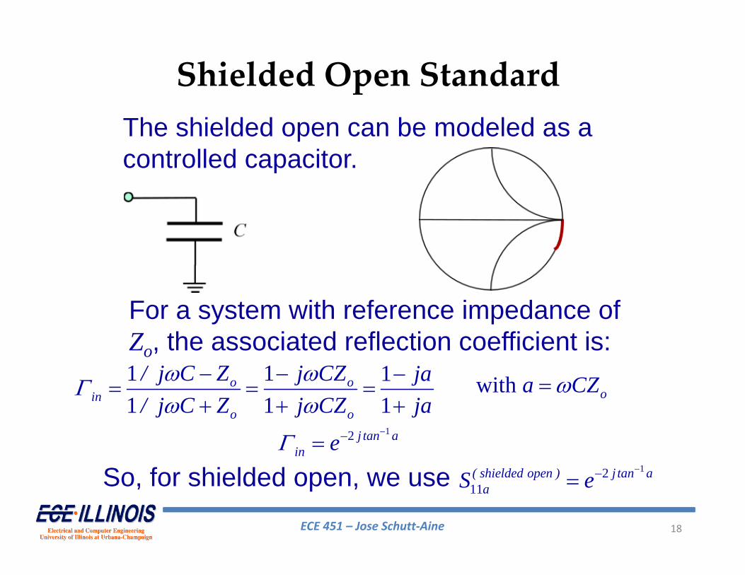
Shielded Open StandardThe shielded open can be modeled as a controlled capacitor.
For a system with reference impedance of Zo, the associated reflection coefficient is:1 1 11 1 1
o oin
o o
/ j C Z j CZ ja/ j C Z j CZ ja
with oa CZ
12 j tan ain e
So, for shielded open, we use 1211( shielded open ) j tan a
aS e
ECE 451 – Jose Schutt‐Aine 19
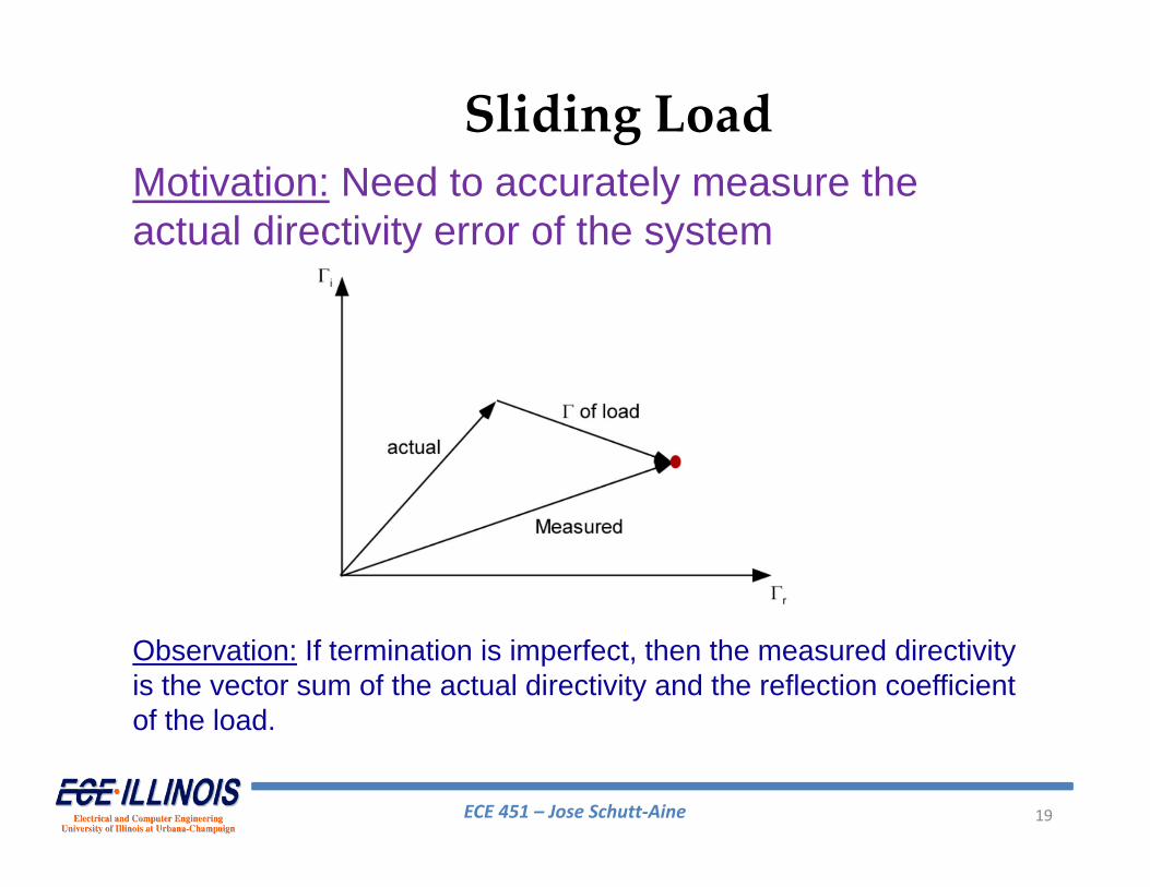
Sliding LoadMotivation: Need to accurately measure the actual directivity error of the system
Observation: If termination is imperfect, then the measured directivity is the vector sum of the actual directivity and the reflection coefficient of the load.
ECE 451 – Jose Schutt‐Aine 20
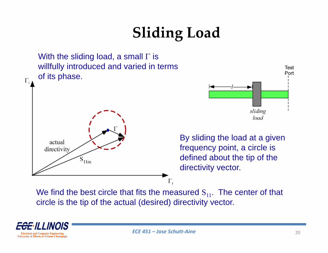
Sliding LoadWith the sliding load, a small is willfully introduced and varied in terms of its phase.
By sliding the load at a given frequency point, a circle is defined about the tip of the directivity vector.
We find the best circle that fits the measured S11. The center of that circle is the tip of the actual (desired) directivity vector.
ECE 451 – Jose Schutt‐Aine 21
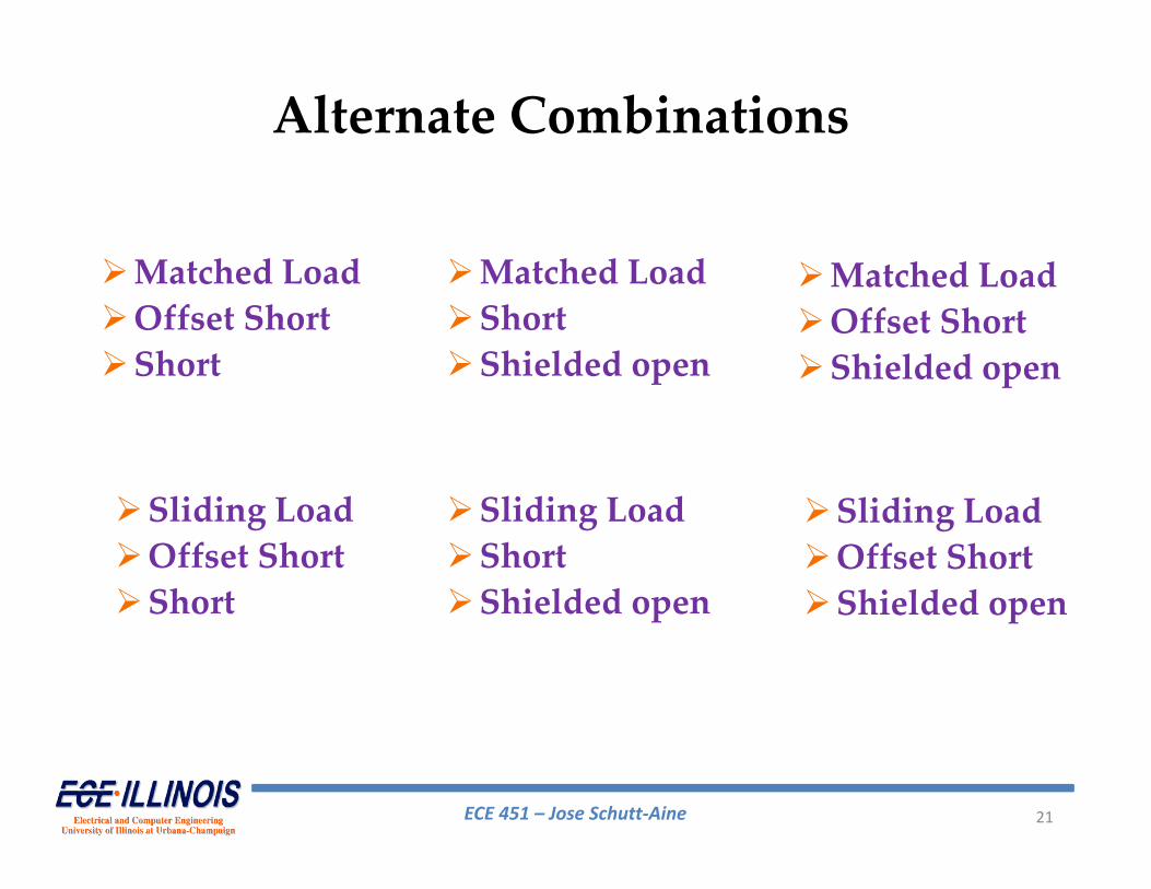
Alternate Combinations
Matched LoadOffset ShortShort
Matched LoadShortShielded open
Matched LoadOffset ShortShielded open
Sliding LoadOffset ShortShort
Sliding LoadShortShielded open
Sliding LoadOffset ShortShielded open
ECE 451 – Jose Schutt‐Aine 22
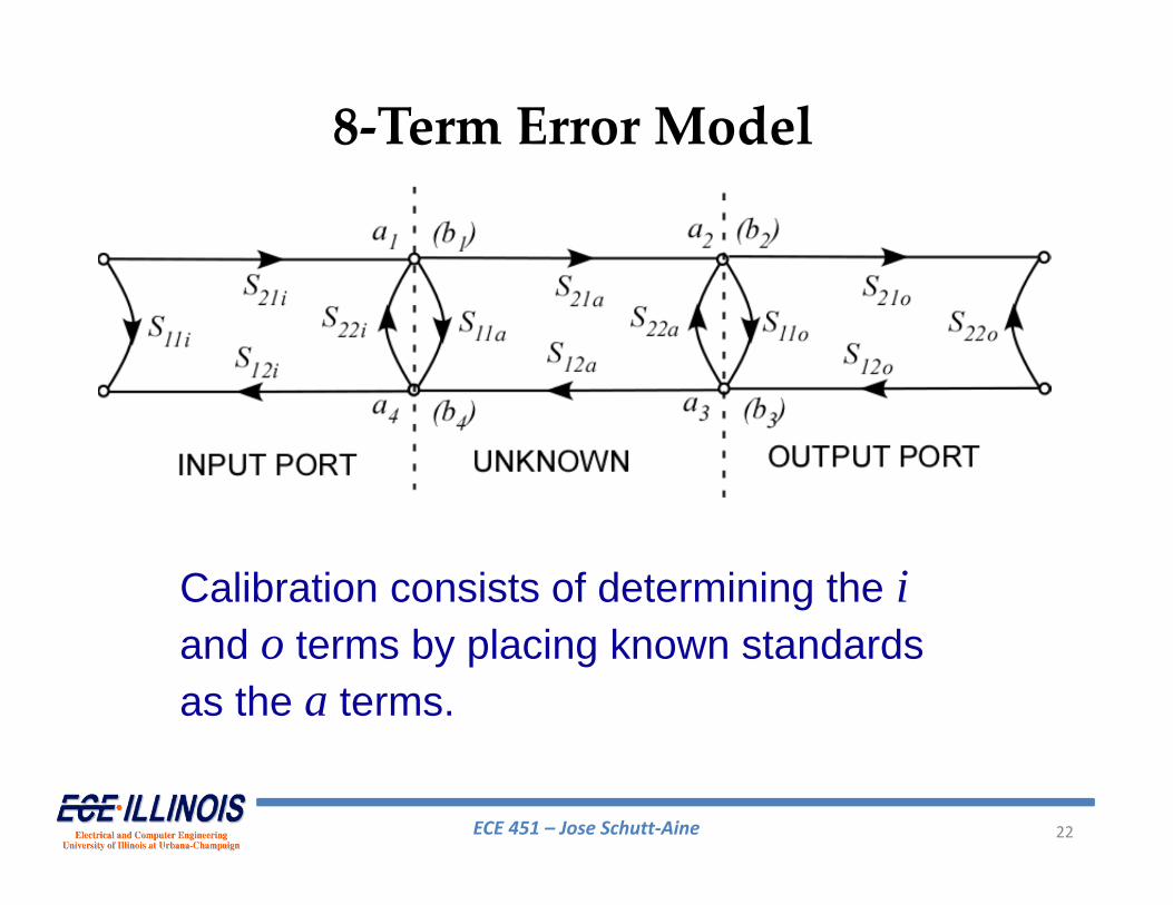
8‐Term Error Model
Calibration consists of determining the iand o terms by placing known standards as the a terms.
ECE 451 – Jose Schutt‐Aine 23
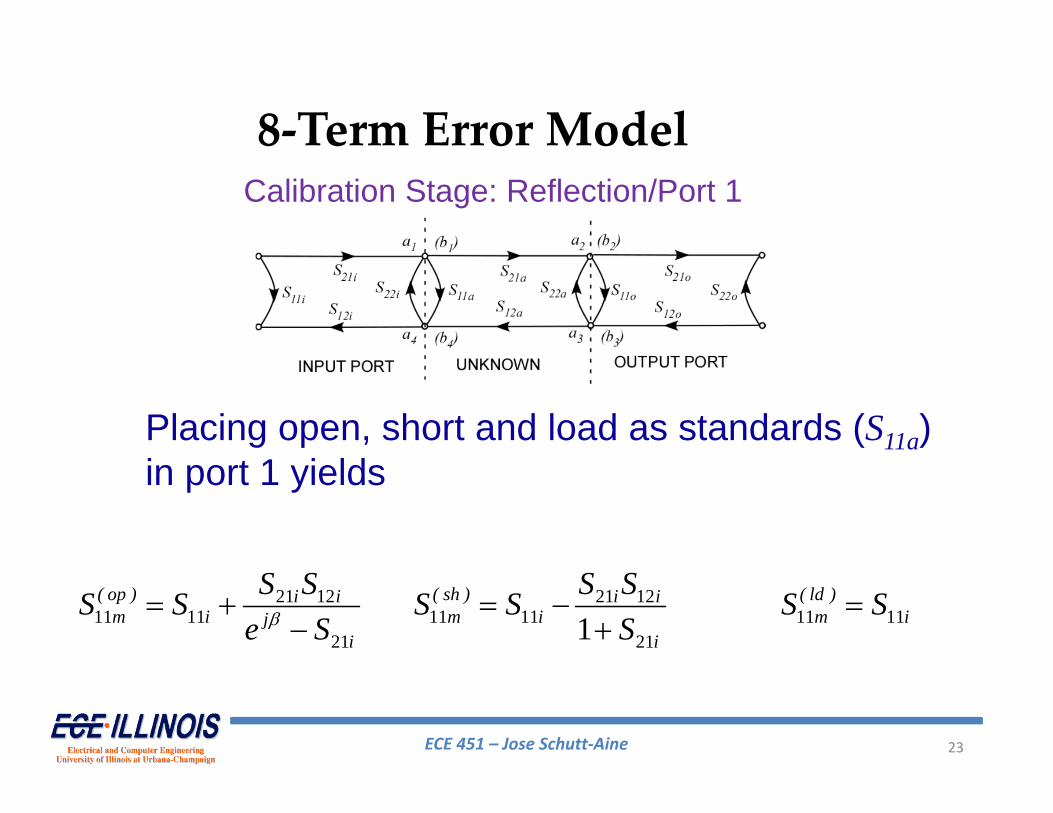
8‐Term Error Model
21 1211 11
21
( op ) i im i j
i
S SS Se S
21 1211 11
211
( sh ) i i
m ii
S SS SS 11 11( ld )
m iS S
Placing open, short and load as standards (S11a) in port 1 yields
Calibration Stage: Reflection/Port 1
ECE 451 – Jose Schutt‐Aine 24
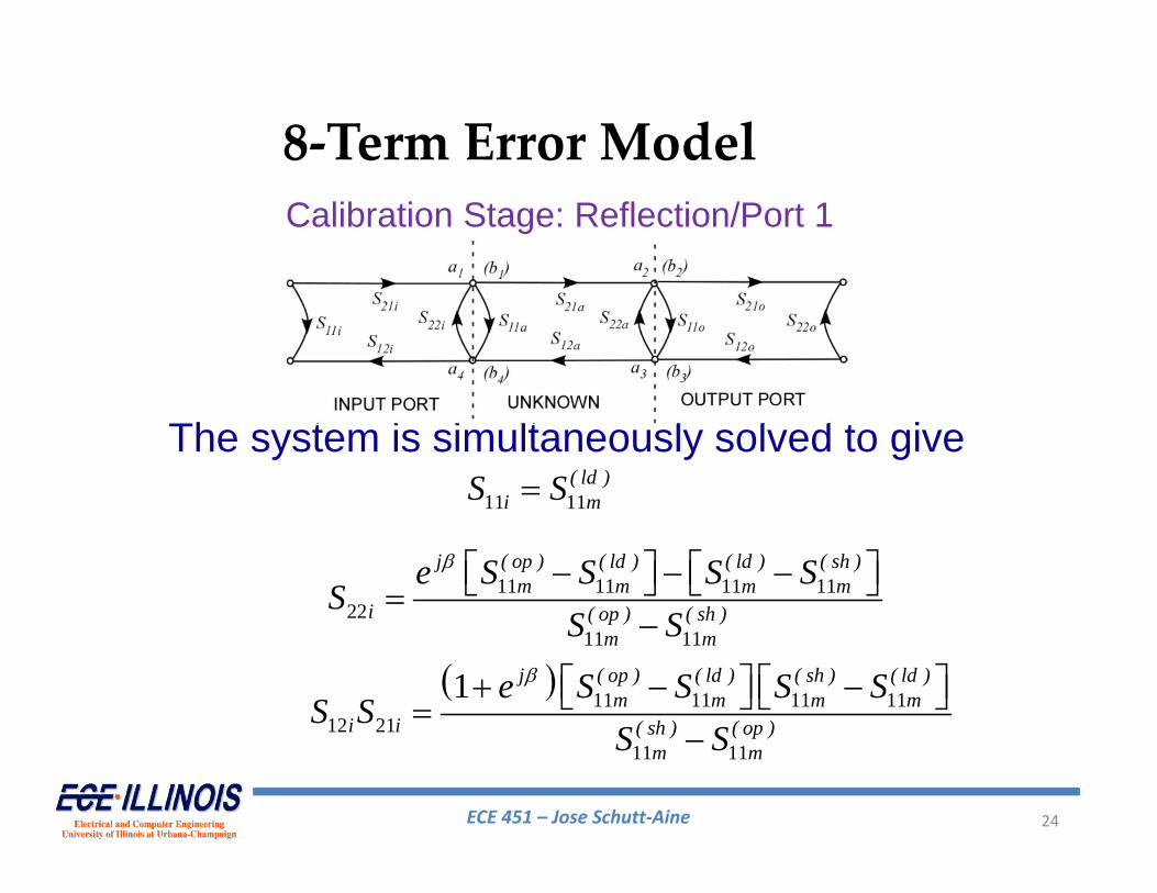
8‐Term Error Model
11 11 ( ld )i mS S
11 11 11 1122
11 11
j ( op ) ( ld ) ( ld ) ( sh )m m m m
i ( op ) ( sh )m m
e S S S SS
S S
11 11 11 11
12 2111 11
1
j ( op ) ( ld ) ( sh ) ( ld )m m m m
i i ( sh ) ( op )m m
e S S S SS S
S S
The system is simultaneously solved to give
Calibration Stage: Reflection/Port 1
ECE 451 – Jose Schutt‐Aine 25
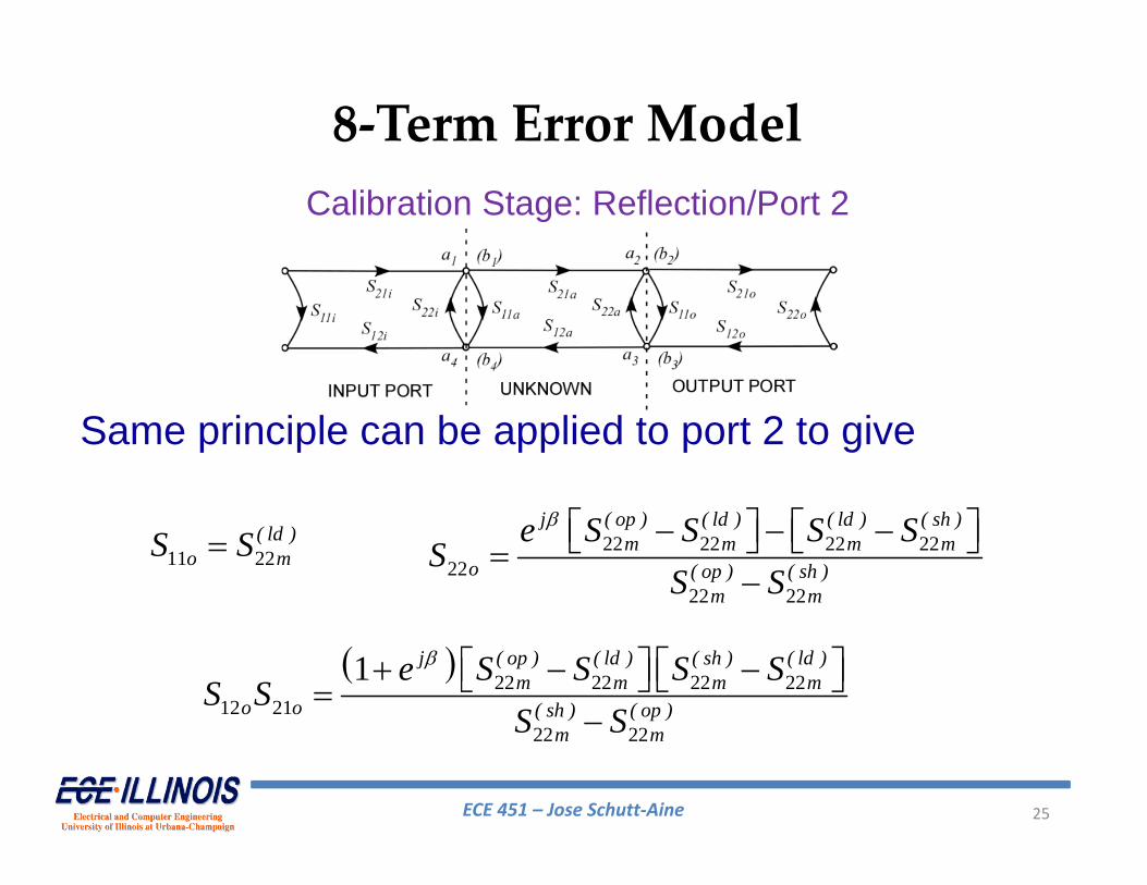
11 22 ( ld )o mS S 22 22 22 22
2222 22
j ( op ) ( ld ) ( ld ) ( sh )m m m m
o ( op ) ( sh )m m
e S S S SS
S S
22 22 22 22
12 2122 22
1
j ( op ) ( ld ) ( sh ) ( ld )m m m m
o o ( sh ) ( op )m m
e S S S SS S
S S
8‐Term Error Model
Same principle can be applied to port 2 to give
Calibration Stage: Reflection/Port 2
ECE 451 – Jose Schutt‐Aine 26
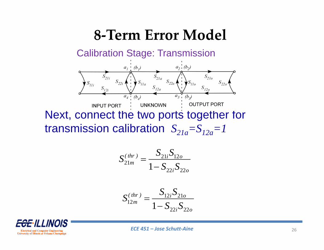
21 1221
22 221( thr ) i o
mi o
S SSS S
8‐Term Error Model
12 2112
22 221
( thr ) i o
mi o
S SSS S
Next, connect the two ports together for transmission calibration S21a=S12a=1
Calibration Stage: Transmission
ECE 451 – Jose Schutt‐Aine 27
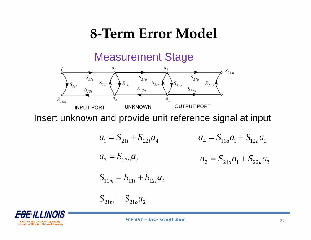
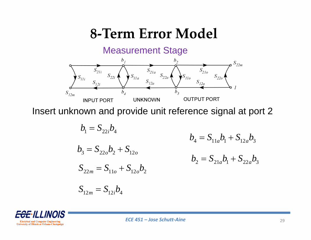
1 21 22 4 i ia S S a
8‐Term Error Model
3 22 2 oa S a
11 11 12 4 m i iS S S a
21 21 2m oS S a
4 11 1 12 3 a aa S a S a
2 21 1 22 3 a aa S a S a
Insert unknown and provide unit reference signal at input
Measurement Stage
ECE 451 – Jose Schutt‐Aine 28
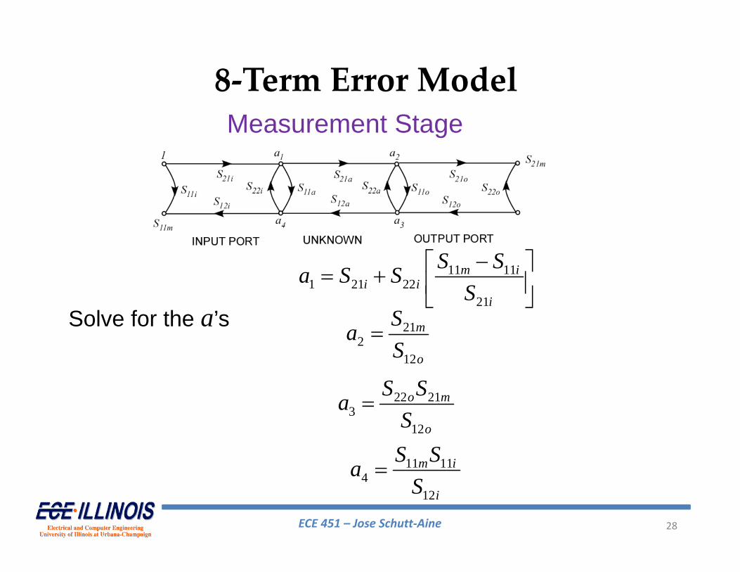
11 111 21 22
21
m ii i
i
S Sa S SS
8‐Term Error Model
212
12
m
o
SaS
22 213
12
o m
o
S SaS
11 114
12
m i
i
S SaS
Solve for the a’s
Measurement Stage
ECE 451 – Jose Schutt‐Aine 29
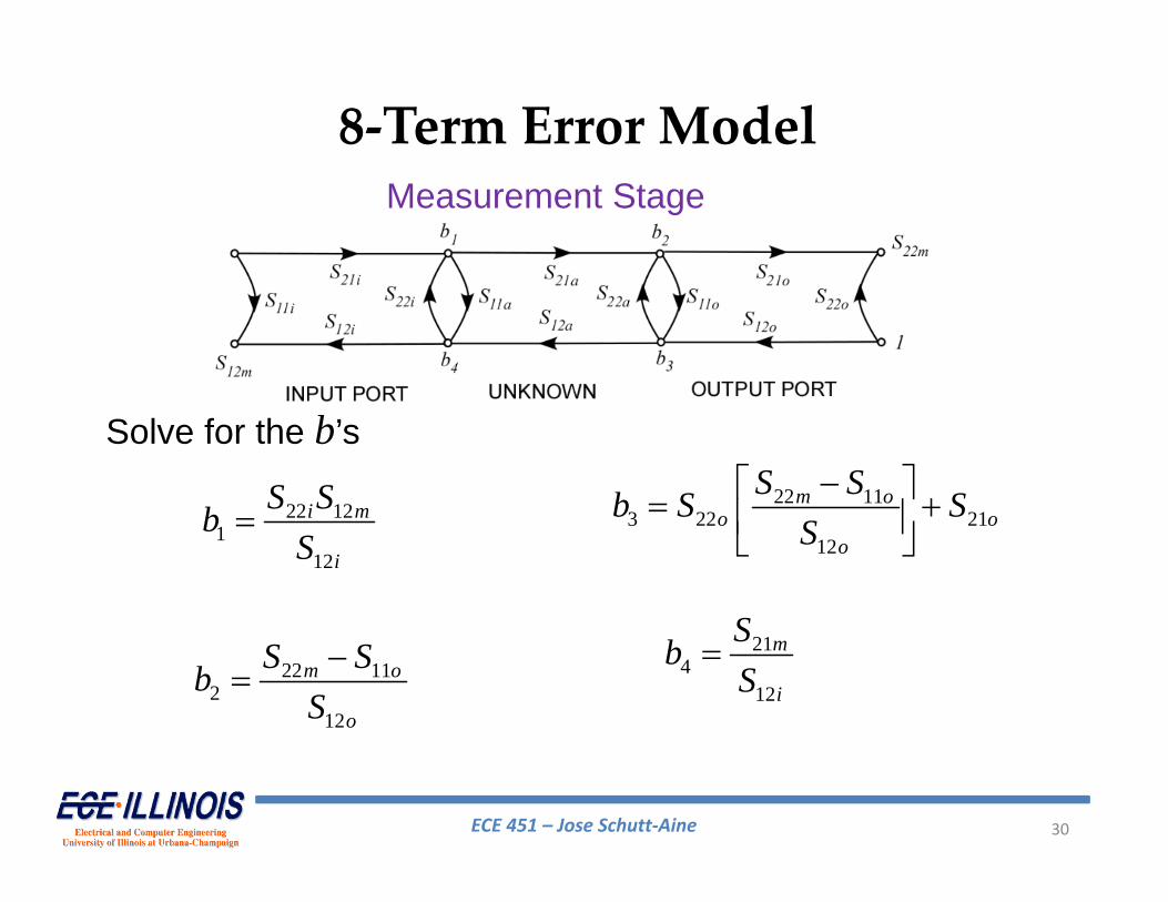
1 22 4 ib S b
8‐Term Error Model
3 22 2 12 o ob S b S
22 11 12 2 m o oS S S b
12 12 4m iS S b
4 11 1 12 3 a ab S b S b
2 21 1 22 3 a ab S b S b
Insert unknown and provide unit reference signal at port 2
Measurement Stage
ECE 451 – Jose Schutt‐Aine 30
22 113 22 21
12
m oo o
o
S Sb S SS
8‐Term Error Model
214
12
m
i
SbS
22 121
12
i m
i
S SbS
22 112
12
m o
o
S SbS
Solve for the b’s
Measurement Stage
ECE 451 – Jose Schutt‐Aine 31
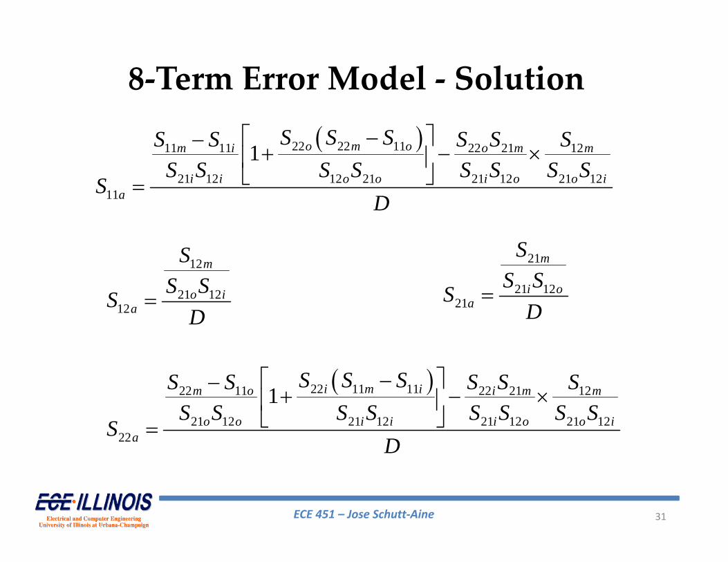
22 22 1111 11 22 21 12
21 12 12 21 21 12 21 1211
1
o m om i o m m
i i o o i o o ia
S S SS S S S SS S S S S S S S
SD
12
21 1212
m
o ia
SS SS
D
21
21 1221
m
i oa
SS SS
D
22 11 1122 11 22 21 12
21 12 21 12 21 12 21 1222
1
i m im o i m m
o o i i i o o ia
S S SS S S S SS S S S S S S S
SD
8‐Term Error Model ‐ Solution
ECE 451 – Jose Schutt‐Aine 32
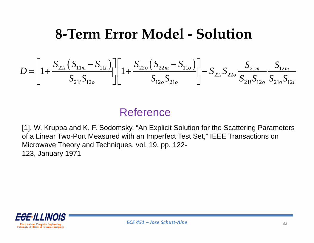
22 11 11 22 22 11 21 1222 22
21 12 12 21 21 12 21 12
1 1
i m i o m o m mi o
i o o o i o o i
S S S S S S S SD S SS S S S S S S S
8‐Term Error Model ‐ Solution
[1]. W. Kruppa and K. F. Sodomsky, “An Explicit Solution for the Scattering Parameters of a Linear Two-Port Measured with an Imperfect Test Set,” IEEE Transactions on Microwave Theory and Techniques, vol. 19, pp. 122-123, January 1971
Reference
ECE 451 – Jose Schutt‐Aine 33
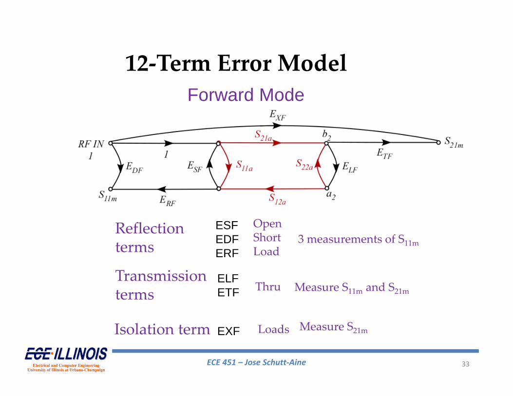
12‐Term Error Model
ESFEDFERF
ELFETF
EXF
Reflectionterms
Transmissionterms
Isolation term
OpenShortLoad
3 measurements of S11m
Measure S11m and S21mThru
Measure S21mLoads
Forward Mode
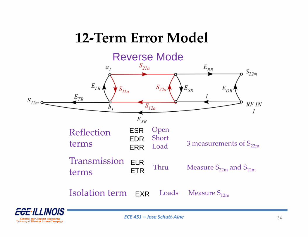
ECE 451 – Jose Schutt‐Aine 34
12‐Term Error ModelReverse Mode
ESREDRERR
ELRETR
EXR
Reflectionterms
Transmissionterms
Isolation term
OpenShortLoad 3 measurements of S22m
Measure S22m and S12mThru
Measure S12mLoads
ECE 451 – Jose Schutt‐Aine 35
Doug Rytting, "Network Analyzer Error Models and Calibration Methods"
For equations and complete development, see
12‐Term Error Model