Embed Size (px)
Citation preview
Installation Guide
www.edge-core.com
ECS4610-26TECS4610-50T24/48-PortLayer 3 Stackable GigabitEthernet Switch

INSTALLATION GUIDE
ECS4610-26T GIGABIT ETHERNET SWITCH
Layer 3 Stackable Gigabit Ethernet Switchwith 20 10/100/1000BASE-T (RJ-45) Ports, 4 Gigabit Combination Ports (RJ-45/SFP),2 10-Gigabit Extender Module Slots,and 2 Stacking Ports
ECS4610-50T GIGABIT ETHERNET SWITCH
Layer 3 Stackable Gigabit Ethernet Switchwith 44 10/100/1000BASE-T (RJ-45) Ports, 4 Gigabit Combination Ports (RJ-45/SFP),2 10-Gigabit Extender Module Slots,and 2 Stacking Ports
ECS4610-26TECS4610-50T
E052010-MW-R01150200000149A

COMPLIANCES AND SAFETY STATEMENTS
FCC - CLASS AThis equipment has been tested and found to comply with the limits for a Class A digital device, pursuant to part 15 of the FCC Rules. These limits are designed to provide reasonable protection against harmful interference when the equipment is operated in a commercial environment. This equipment generates, uses, and can radiate radio frequency energy and, if not installed and used in accordance with the instruction manual, may cause harmful interference to radio communications. Operation of this equipment in a residential area is likely to cause harmful interference in which case the user will be required to correct the interference at his own expense.
You are cautioned that changes or modifications not expressly approved by the party responsible for compliance could void your authority to operate the equipment.
You may use unshielded twisted-pair (UTP) for RJ-45 connections - Category 3 or better for 10 Mbps connections, Category 5 or better for 100 Mbps connections, Category 5, 5e, or 6 for 1000 Mbps connections. For fiber optic connections, you may use 50/125 or 62.5/125 micron multimode fiber or 9/125 micron single-mode fiber.
INDUSTRY CANADA - CLASS AThis digital apparatus does not exceed the Class A limits for radio noise emissions from digital apparatus as set out in the interference-causing equipment standard entitled “Digital Apparatus,” ICES-003 of the Department of Communications.
Cet appareil numérique respecte les limites de bruits radioélectriques applicables aux appareils numériques de Classe A prescrites dans la norme sur le matériel brouilleur: “Appareils Numériques,” NMB-003 édictée par le ministère des Communications.
JAPAN VCCI CLASS A
– 5 –
COMPLIANCES AND SAFETY STATEMENTS
CE MARK DECLARATION OF CONFORMANCE FOR EMI AND SAFETY (EEC)This information technology equipment complies with the requirements of the Council Directive 89/336/EEC on the Approximation of the laws of the Member States relating to Electromagnetic Compatibility and 73/23/EEC for electrical equipment used within certain voltage limits and the Amendment Directive 93/68/EEC. For the evaluation of the compliance with these Directives, the following standards were applied:
RFI Emission: ◆ Limit class A according to EN 55022
◆ Limit class A for harmonic current emission according to EN 61000-3-2
◆ Limitation of voltage fluctuation and flicker in low-voltage supply system according to EN 61000-3-3
Immunity: ◆ Product family standard according to EN 55024
◆ Electrostatic Discharge according to EN 61000-4-2
◆ Radio-frequency electromagnetic field according to EN 61000-4-3
◆ Electrical fast transient/burst according to EN 61000-4-4
◆ Surge immunity test according to EN 61000-4-5
◆ Immunity to conducted disturbances, Induced by radio-frequency fields: EN 61000-4-6
◆ Power frequency magnetic field immunity test according to EN 61000-4-8
◆ Voltage dips, short interruptions and voltage variations immunity test according to EN 61000-4-11
LVD: ◆ EN 60950-1:2001
– 6 –

COMPLIANCES AND SAFETY STATEMENTS
SAFETY COMPLIANCEWarning: Fiber Optic Port Safety
Avertissment: Ports pour fibres optiques - sécurité sur le plan optique
Warnhinweis: Faseroptikanschlüsse - Optische Sicherheit
PSE ALARM本製品に同梱いたしております電源コードセットは、
本製品専用です。本電源コードセットは、本製品以外の
製品並びに他の用途でご使用いただくことは出来ません。
製品本体に同梱された電源コードセットを利用し、他製品
の電源コードセットを使用しないで下さい。
When using a fiber optic port, never look at the transmit laser while it is powered on. Also, never look directly at the fiber TX port and fiber cable ends when they are powered on.
Ne regardez jamais le laser tant qu'il est sous tension. Ne regardez jamais directement le port TX (Transmission) à fibres optiques et les embouts de câbles à fibres optiques tant qu'ils sont sous tension.
Niemals ein Übertragungslaser betrachten, während dieses eingeschaltet ist. Niemals direkt auf den Faser-TX-Anschluß und auf die Faserkabelenden schauen, während diese eingeschaltet sind.
CLASS I
LASER DEVICE
DISPOSITIF LASER
DE CLASSE I
LASERGER
DER KLASSE I
ÄT
– 7 –
COMPLIANCES AND SAFETY STATEMENTS
POWER CORD SAFETYPlease read the following safety information carefully before installing the switch:
WARNING: Installation and removal of the unit must be carried out by qualified personnel only.
◆ The unit must be connected to an earthed (grounded) outlet to comply with international safety standards.
◆ Do not connect the unit to an A.C. outlet (power supply) without an earth (ground) connection.
◆ The appliance coupler (the connector to the unit and not the wall plug) must have a configuration for mating with an EN 60320/IEC 320 appliance inlet.
◆ The socket outlet must be near to the unit and easily accessible. You can only remove power from the unit by disconnecting the power cord from the outlet.
◆ This unit operates under SELV (Safety Extra Low Voltage) conditions according to IEC 60950. The conditions are only maintained if the equipment to which it is connected also operates under SELV conditions.
France and Peru onlyThis unit cannot be powered from IT† supplies. If your supplies are of IT type, this unit must be powered by 230 V (2P+T) via an isolation transformer ratio 1:1, with the secondary connection point labelled Neutral, connected directly to earth (ground).
† Impédance à la terre
IMPORTANT! Before making connections, make sure you have the correct cord set. Check it (read the label on the cable) against the following:
– 8 –

COMPLIANCES AND SAFETY STATEMENTS
Veuillez lire à fond l'information de la sécurité suivante avant d'installer le Switch:
AVERTISSEMENT: L’installation et la dépose de ce groupe doivent être confiés à un personnel qualifié.
◆ Ne branchez pas votre appareil sur une prise secteur (alimentation électrique) lorsqu'il n'y a pas de connexion de mise à la terre (mise à la masse).
◆ Vous devez raccorder ce groupe à une sortie mise à la terre (mise à la masse) afin de respecter les normes internationales de sécurité.
◆ Le coupleur d’appareil (le connecteur du groupe et non pas la prise murale) doit respecter une configuration qui permet un branchement sur une entrée d’appareil EN 60320/IEC 320.
Power Cord Set
U.S.A. and Canada The cord set must be UL-approved and CSA certified.
The minimum specifications for the flexible cord are:- No. 18 AWG - not longer than 2 meters, or 16 AWG.- Type SV or SJ- 3-conductor
The cord set must have a rated current capacity of at least 10 A
The attachment plug must be an earth-grounding type with NEMA 5-15P (15 A, 125 V) configuration.
Denmark The supply plug must comply with Section 107-2-D1, Standard DK2-1a or DK2-5a.
Switzerland The supply plug must comply with SEV/ASE 1011.
U.K. The supply plug must comply with BS1363 (3-pin 13 A) and be fitted with a 5 A fuse which complies with BS1362.
The mains cord must be <HAR> or <BASEC> marked and be of type HO3VVF3GO.75 (minimum).
Europe The supply plug must comply with CEE7/7 (“SCHUKO”).
The mains cord must be <HAR> or <BASEC> marked and be of type HO3VVF3GO.75 (minimum).
IEC-320 receptacle.
– 9 –

COMPLIANCES AND SAFETY STATEMENTS
◆ La prise secteur doit se trouver à proximité de l’appareil et son accès doit être facile. Vous ne pouvez mettre l’appareil hors circuit qu’en débranchant son cordon électrique au niveau de cette prise.
◆ L’appareil fonctionne à une tension extrêmement basse de sécurité qui est conforme à la norme IEC 60950. Ces conditions ne sont maintenues que si l’équipement auquel il est raccordé fonctionne dans les mêmes conditions.
France et Pérou uniquement:Ce groupe ne peut pas être alimenté par un dispositif à impédance à la terre. Si vos alimentations sont du type impédance à la terre, ce groupe doit être alimenté par une tension de 230 V (2 P+T) par le biais d’un transformateur d’isolement à rapport 1:1, avec un point secondaire de connexion portant l’appellation Neutre et avec raccordement direct à la terre (masse).
Cordon électrique - Il doit être agréé dans le pays d’utilisation
Etats-Unis et Canada: Le cordon doit avoir reçu l’homologation des UL et un certificat de la CSA.
Les spécifications minimales pour un cable flexible sont AWG No. 18, ouAWG No. 16 pour un cable de longueur inférieure à 2 mètres.- type SV ou SJ- 3 conducteurs
Le cordon doit être en mesure d’acheminer un courant nominal d’au moins 10 A.
La prise femelle de branchement doit être du type à mise à la terre (mise à la masse) et respecter la configuration NEMA 5-15P (15 A, 125 V).
Danemark: La prise mâle d’alimentation doit respecter la section 107-2 D1 de la norme DK2 1a ou DK2 5a.
Suisse: La prise mâle d’alimentation doit respecter la norme SEV/ASE 1011.
Europe La prise secteur doit être conforme aux normes CEE 7/7 (“SCHUKO”)LE cordon secteur doit porter la mention <HAR> ou <BASEC> et doit être de type HO3VVF3GO.75 (minimum).
– 10 –

COMPLIANCES AND SAFETY STATEMENTS
Bitte unbedingt vor dem Einbauen des Switches die folgenden Sicherheitsanweisungen durchlesen:
WARNUNG: Die Installation und der Ausbau des Geräts darf nur durch Fachpersonal erfolgen.
◆ Das Gerät sollte nicht an eine ungeerdete Wechselstromsteckdose angeschlossen werden.
◆ Das Gerät muß an eine geerdete Steckdose angeschlossen werden, welche die internationalen Sicherheitsnormen erfüllt.
◆ Der Gerätestecker (der Anschluß an das Gerät, nicht der Wandsteckdosenstecker) muß einen gemäß EN 60320/IEC 320 konfigurierten Geräteeingang haben.
◆ Die Netzsteckdose muß in der Nähe des Geräts und leicht zugänglich sein. Die Stromversorgung des Geräts kann nur durch Herausziehen des Gerätenetzkabels aus der Netzsteckdose unterbrochen werden.
◆ Der Betrieb dieses Geräts erfolgt unter den SELV-Bedingungen (Sicherheitskleinstspannung) gemäß IEC 60950. Diese Bedingungen sind nur gegeben, wenn auch die an das Gerät angeschlossenen Geräte unter SELV-Bedingungen betrieben werden.
Stromkabel. Dies muss von dem Land, in dem es benutzt wird geprüft werden:
Schweiz Dieser Stromstecker muß die SEV/ASE 1011Bestimmungen einhalten.
Europe Das Netzkabel muß vom Typ HO3VVF3GO.75 (Mindestanforderung) sein und die Aufschrift <HAR> oder <BASEC> tragen.Der Netzstecker muß die Norm CEE 7/7 erfüllen (”SCHUKO”).
– 11 –
COMPLIANCES AND SAFETY STATEMENTS
WARNINGS AND CAUTIONARY MESSAGES
ENVIRONMENTAL STATEMENTSThe manufacturer of this product endeavours to sustain an environmentally-friendly policy throughout the entire production process. This is achieved though the following means:
◆ Adherence to national legislation and regulations on environmental production standards.
◆ Conservation of operational resources.
◆ Waste reduction and safe disposal of all harmful un-recyclable by-products.
◆ Recycling of all reusable waste content.
◆ Design of products to maximize recyclables at the end of the product’s life span.
◆ Continual monitoring of safety standards.
WARNING: This product does not contain any serviceable user parts.
WARNING: Installation and removal of the unit must be carried out by qualified personnel only.
WARNING: When connecting this device to a power outlet, connect the field ground lead on the tri-pole power plug to a valid earth ground line to prevent electrical hazards.
WARNING: This switch uses lasers to transmit signals over fiber optic cable. The lasers are compliant with the requirements of a Class 1 Laser Product and are inherently eye safe in normal operation. However, you should never look directly at a transmit port when it is powered on.
CAUTION: Wear an anti-static wrist strap or take other suitable measures to prevent electrostatic discharge when handling this equipment.
CAUTION: Do not plug a phone jack connector in the RJ-45 port. This may damage this device.
CAUTION: Use only twisted-pair cables with RJ-45 connectors that conform to FCC standards.
– 12 –

COMPLIANCES AND SAFETY STATEMENTS
END OF PRODUCT LIFE SPANThis product is manufactured in such a way as to allow for the recovery and disposal of all included electrical components once the product has reached the end of its life.
MANUFACTURING MATERIALSThere are no hazardous nor ozone-depleting materials in this product.
DOCUMENTATIONAll printed documentation for this product uses biodegradable paper that originates from sustained and managed forests. The inks used in the printing process are non-toxic.
– 13 –

COMPLIANCES AND SAFETY STATEMENTS
– 14 –
ABOUT THIS GUIDE
PURPOSEThis guide details the hardware features of the switch, including the physical and performance-related characteristics, and how to install the switch.
AUDIENCEThe guide is intended for use by network administrators who are responsible for installing and setting up network equipment; consequently, it assumes a basic working knowledge of LANs (Local Area Networks).
CONVENTIONSThe following conventions are used throughout this guide to show information:
RELATED PUBLICATIONSThe following publication gives specific information on how to operate and use the management functions of the switch:
The Management Guide
Also, as part of the switch’s software, there is an online web-based help that describes all management related features.
NOTE: Emphasizes important information or calls your attention to related features or instructions.
CAUTION: Alerts you to a potential hazard that could cause loss of data, or damage the system or equipment.
WARNING: Alerts you to a potential hazard that could cause personal injury.
– 15 –

ABOUT THIS GUIDE
REVISION HISTORYThis section summarizes the changes in each revision of this guide.
MAY 2010 REVISIONThis is the first revision of this guide.
– 16 –
CONTENTS
COMPLIANCES AND SAFETY STATEMENTS 5
ABOUT THIS GUIDE 15
CONTENTS 17
TABLES 19
FIGURES 21
1 INTRODUCTION 23
Overview 23
Description of Hardware 25
Features and Benefits 30
2 NETWORK PLANNING 33
Introduction to Switching 33
Application Examples 34
Application Notes 39
3 INSTALLING THE SWITCH 41
Selecting a Site 41
Ethernet Cabling 42
Equipment Checklist 43
Mounting 44
Installing an Optional Module into the Switch 47
Installing an Optional SFP Transceiver 48
Connecting Switches in a Stack 49
Connecting to a Power Source 51
Connecting to the Console Port 52
– 17 –
CONTENTS
4 MAKING NETWORK CONNECTIONS 55
Connecting Network Devices 55
Twisted-Pair Devices 55
Fiber Optic SFP Devices 58
10 Gbps Fiber Optic Connections 61
Connectivity Rules 63
Cable Labeling and Connection Records 65
A TROUBLESHOOTING 67
Diagnosing Switch Indicators 67
Power and Cooling Problems 69
Installation 69
In-Band Access 69
Stack Troubleshooting 70
B CABLES 71
Twisted-Pair Cable and Pin Assignments 71
Fiber Standards 75
C SPECIFICATIONS 77
Physical Characteristics 77
Switch Features 79
Management Features 80
Standards 80
Compliances 81
10GBASE Extender Module (XFP) 81
GLOSSARY 83
INDEX 89
– 18 –
TABLES
Table 1: Port Status LEDs 26
Table 2: System Status LEDs 27
Table 3: Supported XFP Transceivers 29
Table 4: Module LEDs 29
Table 5: Serial Cable Wiring 52
Table 6: Maximum 1000BASE-SX Gigabit Ethernet Cable Lengths 63
Table 7: Maximum 10GBASE-LR 10 Gigabit Ethernet Cable Length 63
Table 8: Maximum 10GBASE-ER 10 Gigabit Ethernet Cable Length 64
Table 9: Maximum 1000BASE-T Gigabit Ethernet Cable Length 64
Table 10: Maximum 1000BASE-SX Gigabit Ethernet Cable Lengths 64
Table 11: Maximum 1000BASE-LX Gigabit Ethernet Cable Length 64
Table 12: Maximum 1000BASE-LH Gigabit Ethernet Cable Length 64
Table 13: Maximum Fast Ethernet Cable Lengths 65
Table 14: Maximum Ethernet Cable Length 65
Table 15: Troubleshooting Chart 67
Table 16: Power/RPS LEDs 68
Table 17: 10/100BASE-TX MDI and MDI-X Port Pinouts 72
Table 18: 1000BASE-T MDI and MDI-X Port Pinouts 74
Table 19: Fiber Standards 75
– 19 –

TABLES
– 20 –

FIGURES
Figure 1: Front Panels 24
Figure 2: Rear Panel 24
Figure 3: Port LEDs 26
Figure 4: System LEDs 27
Figure 5: Power Supply Sockets 28
Figure 6: Single-Port 10GBASE Module (XFP) 29
Figure 7: Collapsed Backbone 34
Figure 8: Network Aggregation Plan 35
Figure 9: Remote Connections with Fiber Cable 36
Figure 10: Making VLAN Connections 37
Figure 11: IP Routing for Unicast Traffi 38
Figure 12: RJ-45 Connections 42
Figure 13: Attaching the Brackets 45
Figure 14: Installing the Switch in a Rack 45
Figure 15: Attaching the Adhesive Feet 46
Figure 16: Installing an Optional Module 47
Figure 17: Inserting an SFP Transceiver into a Slot 48
Figure 18: Making Stacking Connections 50
Figure 19: Power Socket 51
Figure 20: Serial Port (RJ-45) Pin-Out 52
Figure 21: Making Twisted-Pair Connections 56
Figure 22: Network Wiring Connections 58
Figure 23: Making Fiber Port Connections 59
Figure 24: Connecting to an XFP Transceiver 62
Figure 25: RJ-45 Connector Pin Numbers 71
Figure 26: Straight-through Wiring 73
Figure 27: Crossover Wiring 73
– 21 –

FIGURES
– 22 –
1 INTRODUCTION
OVERVIEW
The ECS4610-26T and ECS4610-50T Switches are intelligent multilayer switches (Layer 2, 3) with 24/48 10/100/1000BASE-T ports, four of which are combination ports1 that are shared with four SFP transceiver slots (see Figure 1, Ports 21-24/45-48). The rear panel provides two slots for single-port 10 Gigabit Ethernet hot-swappable expansion modules, and two stacking ports. Units can be stacked up to eight high through the built-in stacking ports that provide a 48 Gbps stack backplane.
The switches include an SNMP-based management agent embedded on the main board, which supports both in-band and out-of-band access for managing the stack.
These switches can easily tame your network with full support for Spanning Tree Protocol, Multicast Switching, Virtual LANs, and IP routing. It brings order to poorly performing networks by segregating them into separate broadcast domains with IEEE 802.1Q compliant VLANs, empowers multimedia applications with multicast switching and CoS services, and eliminates conventional router bottlenecks.
These switches can be used to augment or completely replace slow legacy routers, off-loading local IP traffic to release valuable resources for non-IP routing or WAN access. With wire-speed performance for Layer 2 and Layer 3, these switches can significantly improve the throughput between IP segments or VLANs.
1. If an SFP transceiver is plugged in, the corresponding RJ-45 port is disabled for ports 21-24 on ECS4610-26T or ports 45-48 on ECS4610-50T.
– 23 –
CHAPTER 1 | IntroductionOverview
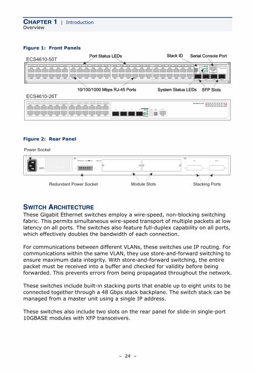
Figure 1: Front Panels
Figure 2: Rear Panel
SWITCH ARCHITECTUREThese Gigabit Ethernet switches employ a wire-speed, non-blocking switching fabric. This permits simultaneous wire-speed transport of multiple packets at low latency on all ports. The switches also feature full-duplex capability on all ports, which effectively doubles the bandwidth of each connection.
For communications between different VLANs, these switches use IP routing. For communications within the same VLAN, they use store-and-forward switching to ensure maximum data integrity. With store-and-forward switching, the entire packet must be received into a buffer and checked for validity before being forwarded. This prevents errors from being propagated throughout the network.
These switches include built-in stacking ports that enable up to eight units to be connected together through a 48 Gbps stack backplane. The switch stack can be managed from a master unit using a single IP address.
These switches also include two slots on the rear panel for slide-in single-port 10GBASE modules with XFP transceivers.
Serial Console Port
10/100/1000 Mbps RJ-45 Ports SFP Slots
Port Status LEDs
System Status LEDs
Stack IDECS4610-50T
ECS4610-26T1 2 3 4 5 6 7 8 9 10 11 12 13 14 15 16 17 18 19 20 21 22 23 24
21 22 23 24
StackMaster Power
Module Diag
StackLink
Stack ID
RPU
ES4626H
MasterSelect
ConsoleStack ID21 22 23 24
Serial Console Port
10/100/1000 Mbps RJ-45 Ports SFP Slots
Port Status LEDs
System Status LEDs
Stack ID
Stacking Ports
Power Socket
Redundant Power Socket Module Slots
– 24 –
CHAPTER 1 | IntroductionDescription of Hardware
NETWORK MANAGEMENT OPTIONSThese switches contain a comprehensive array of LEDs for “at-a-glance” monitoring of network and port status. They also include a management agent that allows you to configure or monitor the switch using its embedded management software, or via SNMP applications. To manage each switch, you can make a direct connection to the console port (out-of-band), or you can manage the switches through a network connection (in-band) using Telnet, the on-board web agent, or SNMP-based network management software.
For a detailed description of the management features, refer to the Management Guide.
DESCRIPTION OF HARDWARE
10/100/1000BASE-T PORTSThe switches contain 24/48 RJ-45 ports that operate at 10 Mbps or 100 Mbps, half or full duplex, or at 1000 Mbps, full duplex. Because all ports on these switches support automatic MDI/MDI-X operation, you can use straight-through cables for all network connections to PCs or servers, or to other switches or hubs. (See “1000BASE-T Pin Assignments” on page 74.)
Each of these ports support auto-negotiation, so the optimum transmission mode (half or full duplex), and data rate (10, 100, or 1000 Mbps) can be selected automatically. If a device connected to one of these ports does not support auto-negotiation, the communication mode of that port can be configured manually.
SFP TRANSCEIVER SLOTSThe Small Form Factor Pluggable (SFP) transceiver slots are shared with four of the RJ-45 ports (ports 21~24 for the ECS4610-26T and ports 45~48 for the ECS4610-50T). In its default configuration, if an SFP transceiver (purchased separately) is installed in a slot and has a valid link on its port, the associated RJ-45 port is disabled and cannot be used. The switch can also be configured to force the use of an RJ-45 port or SFP slot, as required.
– 25 –
CHAPTER 1 | IntroductionDescription of Hardware
10 GIGABIT ETHERNET MODULE SLOTSThese switches include two slots on the rear panel for hot-swappable single-port 10GBASE modules with XFP transceivers. Refer to “Optional Media Extender Modules” on page 29 for more information on this module and the supported 10G transceivers.
STACKING PORTSEach unit includes two stacking ports that provide a 48 Gbps high-speed serial stack backplane connection. Up to eight 24-port or 48-port switches can be connected together using optional stacking cables. Note that the 24-port and 48-port switches can be mixed in the same stack. The Stack Master button enables one switch in the stack to be selected as the Master unit for managing the entire stack.
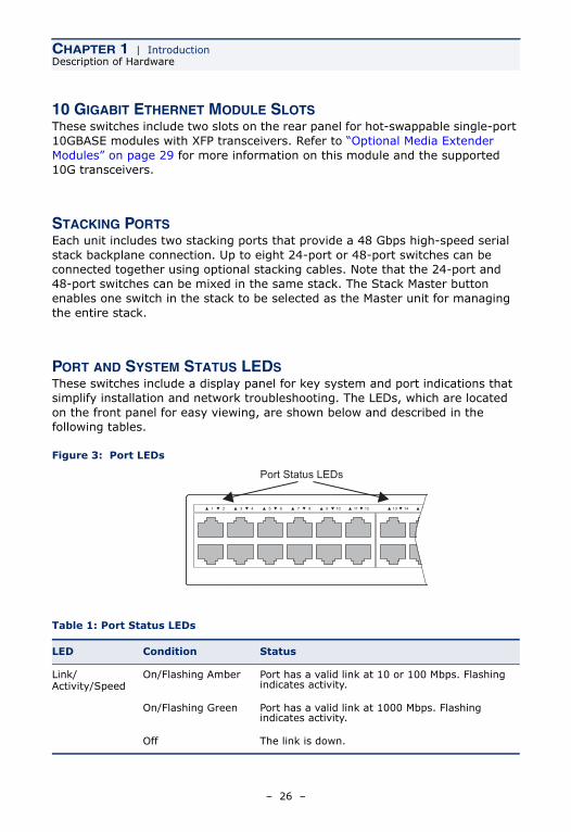
PORT AND SYSTEM STATUS LEDS These switches include a display panel for key system and port indications that simplify installation and network troubleshooting. The LEDs, which are located on the front panel for easy viewing, are shown below and described in the following tables.
Figure 3: Port LEDs
Table 1: Port Status LEDs
LED Condition Status
Link/Activity/Speed
On/Flashing Amber Port has a valid link at 10 or 100 Mbps. Flashing indicates activity.
On/Flashing Green Port has a valid link at 1000 Mbps. Flashing indicates activity.
Off The link is down.
Port Status LEDs
1 2 3 4 5 6 7 8 9 10 11 12 13 14 15
– 26 –
CHAPTER 1 | IntroductionDescription of Hardware
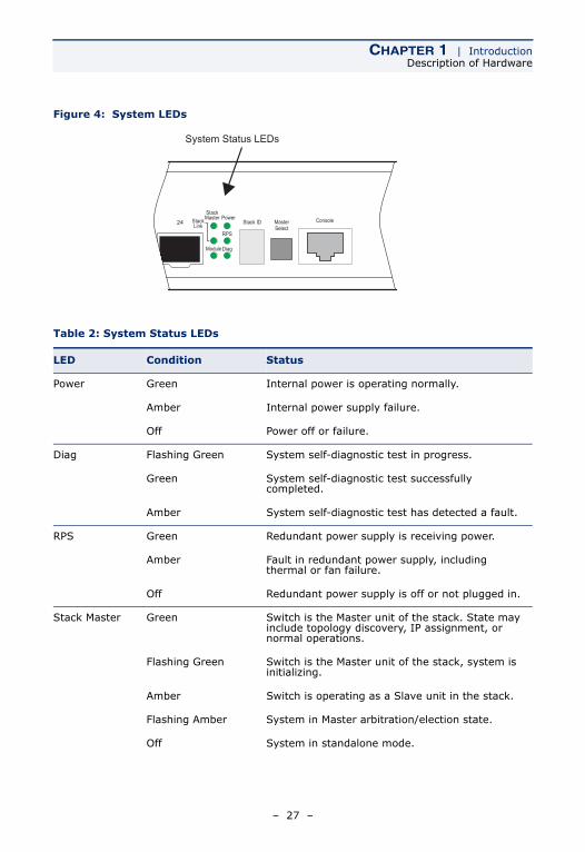
Figure 4: System LEDs
Table 2: System Status LEDs
LED Condition Status
Power Green Internal power is operating normally.
Amber Internal power supply failure.
Off Power off or failure.
Diag Flashing Green System self-diagnostic test in progress.
Green System self-diagnostic test successfully completed.
Amber System self-diagnostic test has detected a fault.
RPS Green Redundant power supply is receiving power.
Amber Fault in redundant power supply, including thermal or fan failure.
Off Redundant power supply is off or not plugged in.
Stack Master Green Switch is the Master unit of the stack. State may include topology discovery, IP assignment, or normal operations.
Flashing Green Switch is the Master unit of the stack, system is initializing.
Amber Switch is operating as a Slave unit in the stack.
Flashing Amber System in Master arbitration/election state.
Off System in standalone mode.
24
StackMaster Power
Module Diag
StackLink
Stack ID
RPU MasterSelect
ConsoleStack IDPower
StackMaster
StackLink
RPS
DiagModule
24
System Status LEDs
– 27 –
CHAPTER 1 | IntroductionDescription of Hardware
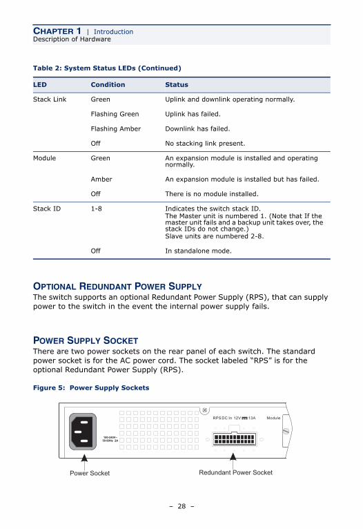
OPTIONAL REDUNDANT POWER SUPPLYThe switch supports an optional Redundant Power Supply (RPS), that can supply power to the switch in the event the internal power supply fails.
POWER SUPPLY SOCKETThere are two power sockets on the rear panel of each switch. The standard power socket is for the AC power cord. The socket labeled “RPS” is for the optional Redundant Power Supply (RPS).
Figure 5: Power Supply Sockets
Stack Link Green Uplink and downlink operating normally.
Flashing Green Uplink has failed.
Flashing Amber Downlink has failed.
Off No stacking link present.
Module Green An expansion module is installed and operating normally.
Amber An expansion module is installed but has failed.
Off There is no module installed.
Stack ID 1-8 Indicates the switch stack ID.The Master unit is numbered 1. (Note that If the master unit fails and a backup unit takes over, the stack IDs do not change.) Slave units are numbered 2-8.
Off In standalone mode.
Table 2: System Status LEDs (Continued)
LED Condition Status
Power Socket Redundant Power Socket
– 28 –
CHAPTER 1 | IntroductionDescription of Hardware
OPTIONAL MEDIA EXTENDER MODULES
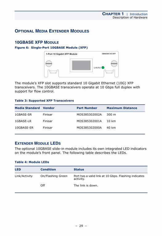
10GBASE XFP MODULE
Figure 6: Single-Port 10GBASE Module (XFP)
The module’s XFP slot supports standard 10 Gigabit Ethernet (10G) XFP transceivers. The 10GBASE transceivers operate at 10 Gbps full duplex with support for flow control.
EXTENDER MODULE LEDS
The optional 10GBASE slide-in module includes its own integrated LED indicators on the module’s front panel. The following table describes the LEDs.
Table 3: Supported XFP Transceivers
Media Standard Vendor Part Number Maximum Distance
1GBASE-SR Finisar MOS385302002A 300 m
1GBASE-LR Finisar MOS385302001A 10 km
10GBASE-ER Finisar MOS385302000A 40 km
Table 4: Module LEDs
LED Condition Status
Link/Activity On/Flashing Green Port has a valid link at 10 Gbps. Flashing indicates activity.
Off The link is down.
– 29 –
CHAPTER 1 | IntroductionFeatures and Benefits
FEATURES AND BENEFITS
CONNECTIVITY◆ 24 or 48 10/100/1000 Mbps ports for easy Gigabit Ethernet integration and
for protection of your investment in legacy LAN equipment.
◆ Auto-negotiation enables each RJ-45 port to automatically select the optimum communication mode (half or full duplex) if this feature is supported by the attached device; otherwise the port can be configured manually.
◆ RJ-45 10/100/1000BASE-T ports support auto MDI/MDI-X pinout selection.
◆ Unshielded (UTP) cable supported on all RJ-45 ports: Category 3 or better for 10 Mbps connections, Category 5 or better for 100 Mbps connections, and Category Category 5, 5e, 6 or better for 1000 Mbps connections.
◆ IEEE 802.3-2005 Ethernet, Fast Ethernet, Gigabit Ethernet, and IEEE 802.3ae 10 Gigabit Ethernet compliance ensures compatibility with standards-based hubs, network cards and switches from any vendor.
◆ Provides stacking capability via high-speed serial ports with 48 Gbps stacking bandwidth. Up to 8 units can be stacked together.
EXPANDABILITY◆ Supports 1000BASE-SX, 1000BASE-LX, and 1000BASE-LH SFP transceivers.
◆ Optional 10GBASE single-port expansion module with an XFP transceiver slot.
PERFORMANCE◆ Transparent bridging.
◆ Aggregate duplex bandwidth of up to 88 Gbps for the ECS4610-26T or 136 Gbps for the ECS4610-50T.
– 30 –
CHAPTER 1 | IntroductionFeatures and Benefits
◆ Switching table with a total of 16K MAC address entries and 8K IPv4 address entries or 4K IPv6 address entries
◆ Provides store-and-forward switching for intra-VLAN traffic, and IP routing for inter-VLAN traffic.
◆ Supports wire-speed switching at layer 2, and wire-speed routing at layer 3.
◆ Broadcast storm control.
MANAGEMENT◆ “At-a-glance” LEDs for easy troubleshooting
◆ Network management agent:
◆ Manages switch (or entire stack) in-band or out-of-band
◆ Supports console, Telnet, SSH, SNMP v1/v2c/v3, RMON (4 groups) and web-based interface
◆ Slave units provide backup stack management.
– 31 –

CHAPTER 1 | IntroductionFeatures and Benefits
– 32 –
2 NETWORK PLANNING
INTRODUCTION TO SWITCHING
A network switch allows simultaneous transmission of multiple packets via non-crossbar switching. This means that it can partition a network more efficiently than bridges or routers. These switches have, therefore, been recognized as one of the most important building blocks for today’s networking technology.
When performance bottlenecks are caused by congestion at the network access point (such as the network card for a high-volume file server), the device experiencing congestion (server, power user or hub) can be attached directly to a switched port. And, by using full-duplex mode, the bandwidth of the dedicated segment can be doubled to maximize throughput.
When networks are based on repeater (hub) technology, the distance between end stations is limited by a maximum hop count. However, a switch turns the hop count back to zero. So subdividing the network into smaller and more manageable segments, and linking them to the larger network by means of a switch, removes this limitation.
A switch can be easily configured in any Ethernet, Fast Ethernet, Gigabit Ethernet, or 10G Ethernet network to significantly boost bandwidth while using conventional cabling and network cards.
– 33 –
CHAPTER 2 | Network PlanningApplication Examples
APPLICATION EXAMPLES
The Gigabit Ethernet Switches are not only designed to segment your network, but also to provide a wide range of options in setting up network connections and linking VLANs or IP subnets. Some typical applications are described below.
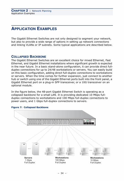
COLLAPSED BACKBONEThe Gigabit Ethernet Switches are an excellent choice for mixed Ethernet, Fast Ethernet, and Gigabit Ethernet installations where significant growth is expected in the near future. In a basic stand-alone configuration, it can provide direct full-duplex connections for up to 24/48 workstations or servers. You can easily build on this basic configuration, adding direct full-duplex connections to workstations or servers. When the time comes for further expansion, just connect to another hub or switch using one of the Gigabit Ethernet ports built into the front panel, a Gigabit Ethernet port on a plug-in SFP transceiver, or a 10G transceiver on an optional module.
In the figure below, the 48-port Gigabit Ethernet Switch is operating as a collapsed backbone for a small LAN. It is providing dedicated 10 Mbps full-duplex connections to workstations and 100 Mbps full-duplex connections to power users, and 1 Gbps full-duplex connections to servers.
Figure 7: Collapsed Backbone
Servers1 GbpsFull Duplex
Workstations100 MbpsFull Duplex
Workstations10 MbpsFull Duplex
... ... ...
– 34 –
CHAPTER 2 | Network PlanningApplication Examples
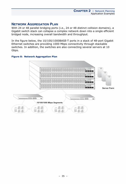
NETWORK AGGREGATION PLANWith 24 or 48 parallel bridging ports (i.e., 24 or 48 distinct collision domains), a Gigabit switch stack can collapse a complex network down into a single efficient bridged node, increasing overall bandwidth and throughput.
In the figure below, the 10/100/1000BASE-T ports in a stack of 48-port Gigabit Ethernet switches are providing 1000 Mbps connectivity through stackable switches. In addition, the switches are also connecting several servers at 10 Gbps.
Figure 8: Network Aggregation Plan
Server Farm
10/100/1000 Mbps Segments
... ...
– 35 –
CHAPTER 2 | Network PlanningApplication Examples
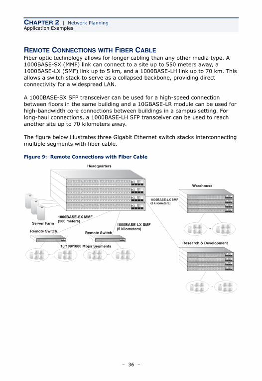
REMOTE CONNECTIONS WITH FIBER CABLEFiber optic technology allows for longer cabling than any other media type. A 1000BASE-SX (MMF) link can connect to a site up to 550 meters away, a 1000BASE-LX (SMF) link up to 5 km, and a 1000BASE-LH link up to 70 km. This allows a switch stack to serve as a collapsed backbone, providing direct connectivity for a widespread LAN.
A 1000BASE-SX SFP transceiver can be used for a high-speed connection between floors in the same building and a 10GBASE-LR module can be used for high-bandwidth core connections between buildings in a campus setting. For long-haul connections, a 1000BASE-LH SFP transceiver can be used to reach another site up to 70 kilometers away.
The figure below illustrates three Gigabit Ethernet switch stacks interconnecting multiple segments with fiber cable.
Figure 9: Remote Connections with Fiber Cable
... ...
1000BASE-LX SMF(5 kilometers)
Remote Switch
1000BASE-SX MMF(500 meters)
Remote Switch
Server Farm...
...
Warehouse
Research & Development
1000BASE-LX SMF(5 kilometers)
10/100/1000 Mbps Segments
Headquarters
– 36 –
CHAPTER 2 | Network PlanningApplication Examples
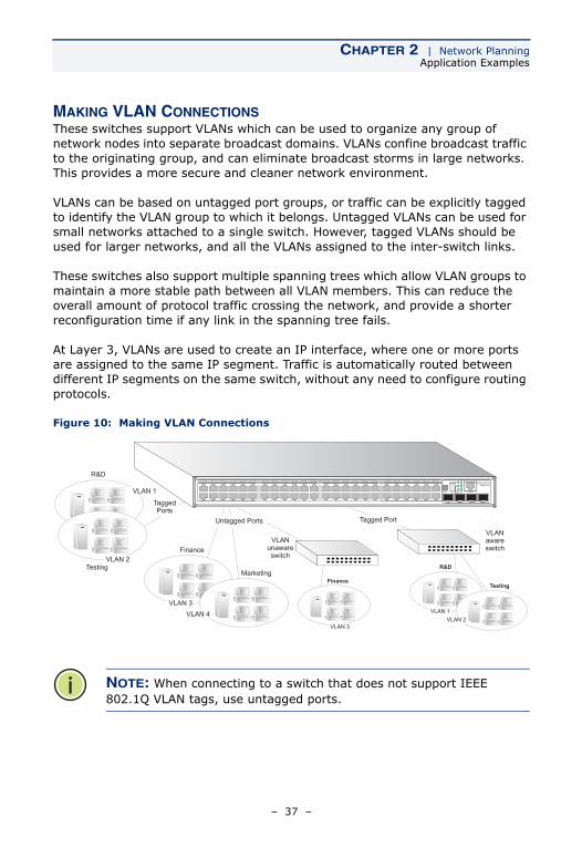
MAKING VLAN CONNECTIONSThese switches support VLANs which can be used to organize any group of network nodes into separate broadcast domains. VLANs confine broadcast traffic to the originating group, and can eliminate broadcast storms in large networks. This provides a more secure and cleaner network environment.
VLANs can be based on untagged port groups, or traffic can be explicitly tagged to identify the VLAN group to which it belongs. Untagged VLANs can be used for small networks attached to a single switch. However, tagged VLANs should be used for larger networks, and all the VLANs assigned to the inter-switch links.
These switches also support multiple spanning trees which allow VLAN groups to maintain a more stable path between all VLAN members. This can reduce the overall amount of protocol traffic crossing the network, and provide a shorter reconfiguration time if any link in the spanning tree fails.
At Layer 3, VLANs are used to create an IP interface, where one or more ports are assigned to the same IP segment. Traffic is automatically routed between different IP segments on the same switch, without any need to configure routing protocols.
Figure 10: Making VLAN Connections
NOTE: When connecting to a switch that does not support IEEE 802.1Q VLAN tags, use untagged ports.
Finance
Marketing
VLAN 3
Untagged Ports
VLANunawareswitch
Tagged Port
VLANawareswitch
TaggedPorts
Finance
VLAN 3
R&D
VLAN 2Testing R&D
Testing
VLAN 1
VLAN 2VLAN 4
VLAN 1
– 37 –
CHAPTER 2 | Network PlanningApplication Examples
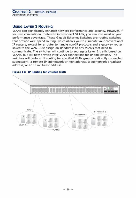
USING LAYER 3 ROUTINGVLANs can significantly enhance network performance and security. However, if you use conventional routers to interconnect VLANs, you can lose most of your performance advantage. These Gigabit Ethernet Switches are routing switches that provide wire-speed routing, which allows you to eliminate your conventional IP routers, except for a router to handle non-IP protocols and a gateway router linked to the WAN. Just assign an IP address to any VLANs that need to communicate. The switches will continue to segregate Layer 2 traffic based on VLANs, but will now provide inter-VLAN connections for IP applications. The switches will perform IP routing for specified VLAN groups, a directly connected subnetwork, a remote IP subnetwork or host address, a subnetwork broadcast address, or an IP multicast address.
Figure 11: IP Routing for Unicast Traffi
IP Network 1
R&D
VLAN 1
VLAN 2
TestingIP Network 2
– 38 –
CHAPTER 2 | Network PlanningApplication Notes
APPLICATION NOTES
1. Full-duplex operation only applies to point-to-point access (such as when a switch is attached to a workstation, server or another switch). When the switch is connected to a hub, both devices must operate in half-duplex mode.
2. For network applications that require routing between dissimilar network types, you can attach these switches directly to a multi-protocol router. However, if you have to interconnect distinct VLANs or IP subnets, you can take advantage of the wire-speed Layer 3 routing provided by these switches.
3. As a general rule, the length of fiber optic cable for a single switched link should not exceed:
■ 1000BASE-SX: 550 m (1805 ft) for multimode fiber
■ 1000BASE-LX: 5 km (3.1 miles) for single-mode fiber
■ 1000BASE-LH: 70 km (43.5 miles) for single-mode fiber
■ 10GBASE-SR: 300 m (984 ft) for multimode fiber
■ 10GBASE-LR: 10 km (6.2 miles) for single-mode fiber
■ 10GBASE-ER: 40 km (24.8 miles) for single-mode fiber
However, power budget constraints must also be considered when calculating the maximum cable length for your specific environment.
– 39 –

CHAPTER 2 | Network PlanningApplication Notes
– 40 –
3 INSTALLING THE SWITCH
SELECTING A SITE
Switch units can be mounted in a standard 19-inch equipment rack or on a flat surface. Be sure to follow the guidelines below when choosing a location.
◆ The site should:
■ be at the center of all the devices you want to link and near a power outlet.
■ be able to maintain its temperature within 0 to 50 °C (32 to 122 °F) and its humidity within 5% to 95%, non-condensing
■ provide adequate space (approximately five centimeters or two inches) on all sides for proper air flow
■ be accessible for installing, cabling and maintaining the devices
■ allow the status LEDs to be clearly visible
◆ Make sure twisted-pair cable is always routed away from power lines, fluorescent lighting fixtures and other sources of electrical interference, such as radios and transmitters.
◆ Make sure that the unit is connected to a separate grounded power outlet that provides 100 to 240 VAC, 50 to 60 Hz, is within 2 m (6.6 feet) of each device and is powered from an independent circuit breaker. As with any equipment, using a filter or surge suppressor is recommended.
– 41 –
CHAPTER 3 | Installing the SwitchEthernet Cabling
ETHERNET CABLING
To ensure proper operation when installing the switches into a network, make sure that the current cables are suitable for 10BASE-T, 100BASE-TX or 1000BASE-T operation. Check the following criteria against the current installation of your network:
◆ Cable type: Unshielded twisted pair (UTP) or shielded twisted pair (STP) cables with RJ-45 connectors; Category 3 or better for 10BASE-T, Category 5 or better for 100BASE-TX, and Category 5, 5e or 6 for 1000BASE-T.
◆ Protection from radio frequency interference emissions
◆ Electrical surge suppression
◆ Separation of electrical wires (switch related or other) and electromagnetic fields from data based network wiring
◆ Safe connections with no damaged cables, connectors or shields
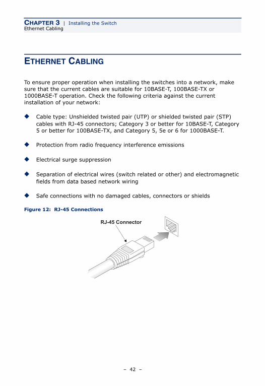
Figure 12: RJ-45 Connections
RJ-45 Connector
– 42 –
CHAPTER 3 | Installing the SwitchEquipment Checklist
EQUIPMENT CHECKLIST
After unpacking this switch, check the contents to be sure you have received all the components. Then, before beginning the installation, be sure you have all other necessary installation equipment.
PACKAGE CONTENTS◆ 24- or 48-port Gigabit Ethernet Switch (ECS4610-26T or ECS4610-50T)
◆ Four adhesive foot pads
◆ Bracket Mounting Kit containing two brackets and eight screws for attaching the brackets to the switch
◆ Power cord—either US, Continental Europe or UK
◆ Console cable (RJ-45 to RS-232)
◆ This Installation Guide
◆ Management Guide CD
OPTIONAL RACK-MOUNTING EQUIPMENTIf you plan to rack-mount the switch, be sure to have the following equipment available:
◆ Four mounting screws for each device you plan to install in a rack—these are not included
◆ A screwdriver (Phillips or flathead, depending on the type of screws used)
– 43 –
CHAPTER 3 | Installing the SwitchMounting
MOUNTING
The switch can be mounted in a standard 19-inch equipment rack or on a desktop or shelf. Mounting instructions for each type of site follow.
RACK MOUNTINGBefore rack mounting the switch, pay particular attention to the following factors:
◆ Temperature: Since the temperature within a rack assembly may be higher than the ambient room temperature, check that the rack-environment temperature is within the specified operating temperature range. (See page 78.)
◆ Mechanical Loading: Do not place any equipment on top of a rack-mounted unit.
◆ Circuit Overloading: Be sure that the supply circuit to the rack assembly is not overloaded.
◆ Grounding: Rack-mounted equipment should be properly grounded. Particular attention should be given to supply connections other than direct connections to the mains.
To rack-mount devices:
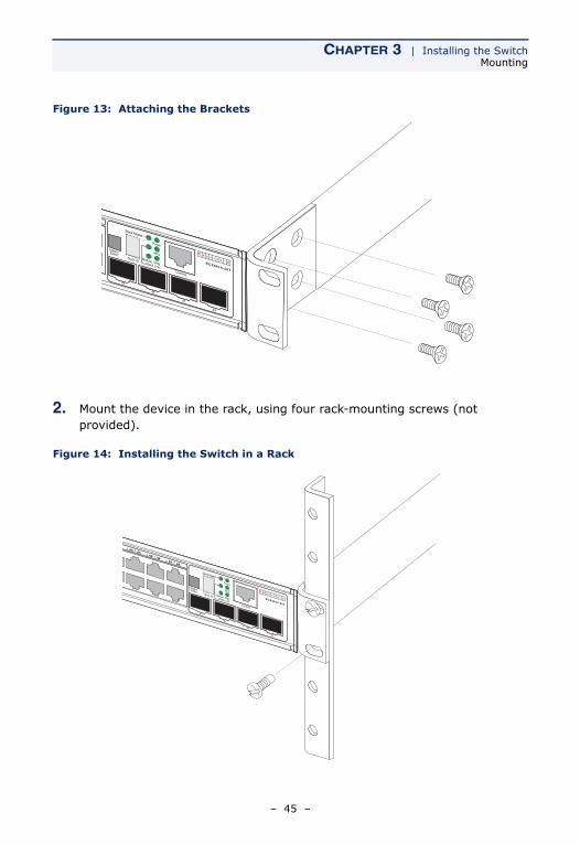
1. Attach the brackets to the device using the screws provided in the Bracket Mounting Kit.
– 44 –
CHAPTER 3 | Installing the SwitchMounting
Figure 13: Attaching the Brackets
2. Mount the device in the rack, using four rack-mounting screws (not provided).
Figure 14: Installing the Switch in a Rack
– 45 –
CHAPTER 3 | Installing the SwitchMounting
3. If installing a single switch only, turn to “Connecting to a Power Source” on page 51.
4. If installing multiple switches, mount them in the rack, one below the other, in any order.
5. If also installing an RPS, mount it in the rack below the other devices.
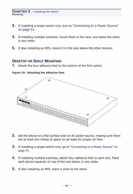
DESKTOP OR SHELF MOUNTING1. Attach the four adhesive feet to the bottom of the first switch.
Figure 15: Attaching the Adhesive Feet
2. Set the device on a flat surface near an AC power source, making sure there are at least two inches of space on all sides for proper air flow.
3. If installing a single switch only, go to “Connecting to a Power Source” on page 51.
4. If installing multiple switches, attach four adhesive feet to each one. Place each device squarely on top of the one below, in any order.
5. If also installing an RPS, place it close to the stack.
– 46 –
CHAPTER 3 | Installing the SwitchInstalling an Optional Module into the Switch
INSTALLING AN OPTIONAL MODULE INTO THE SWITCH
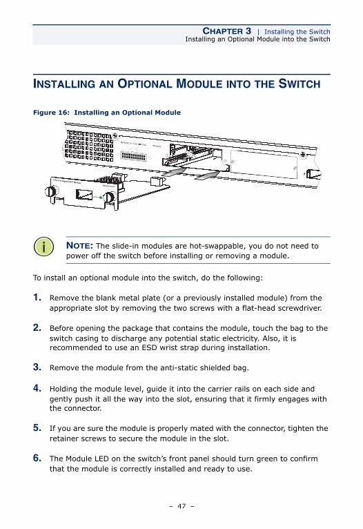
Figure 16: Installing an Optional Module
To install an optional module into the switch, do the following:
1. Remove the blank metal plate (or a previously installed module) from the appropriate slot by removing the two screws with a flat-head screwdriver.
2. Before opening the package that contains the module, touch the bag to the switch casing to discharge any potential static electricity. Also, it is recommended to use an ESD wrist strap during installation.
3. Remove the module from the anti-static shielded bag.
4. Holding the module level, guide it into the carrier rails on each side and gently push it all the way into the slot, ensuring that it firmly engages with the connector.
5. If you are sure the module is properly mated with the connector, tighten the retainer screws to secure the module in the slot.
6. The Module LED on the switch’s front panel should turn green to confirm that the module is correctly installed and ready to use.
NOTE: The slide-in modules are hot-swappable, you do not need to power off the switch before installing or removing a module.
– 47 –
CHAPTER 3 | Installing the SwitchInstalling an Optional SFP Transceiver
INSTALLING AN OPTIONAL SFP TRANSCEIVER
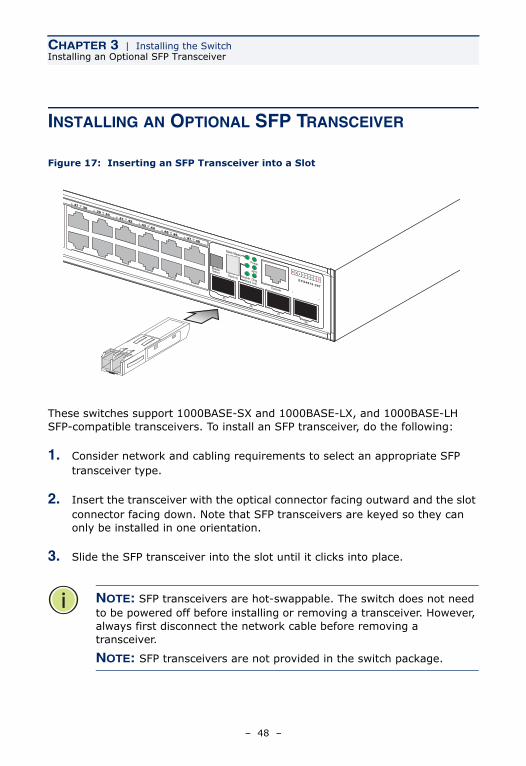
Figure 17: Inserting an SFP Transceiver into a Slot
These switches support 1000BASE-SX and 1000BASE-LX, and 1000BASE-LH SFP-compatible transceivers. To install an SFP transceiver, do the following:
1. Consider network and cabling requirements to select an appropriate SFP transceiver type.
2. Insert the transceiver with the optical connector facing outward and the slot connector facing down. Note that SFP transceivers are keyed so they can only be installed in one orientation.
3. Slide the SFP transceiver into the slot until it clicks into place.
NOTE: SFP transceivers are hot-swappable. The switch does not need to be powered off before installing or removing a transceiver. However, always first disconnect the network cable before removing a transceiver.
NOTE: SFP transceivers are not provided in the switch package.
– 48 –
CHAPTER 3 | Installing the SwitchConnecting Switches in a Stack
CONNECTING SWITCHES IN A STACK
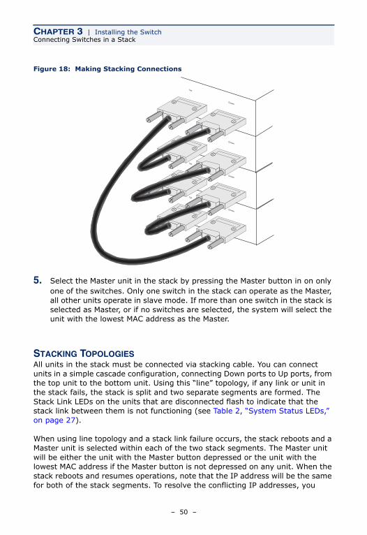
Figure 18 shows how the stack cables are connected between switches in a stack. Each stacking connection is a 48 Gbps full-duplex high-speed serial link using proprietary stacking cables. The switch supports a line- and ring-topology stacking configuration, or can be used stand alone. To ensure minimal disruption in case a unit or stacking cable fails, we recommend always use a ring-topology.
In line-topology stacking there is a single stack cable connection between each switch that carries two-way communications across the stack. In ring-topology stacking, an extra cable is connected between the top and bottom switches forming a “ring” or “closed-loop.” The closed-loop cable provides a redundant path for the stack link, so if one link fails, stack communications can still be maintained. Figure 18 illustrates a ring-topology stacking configuration.
To connect up to eight switches in a stack, perform the following steps:
1. Plug one end of the stack cable (ordered separately) in the Down (right) port of the top unit.
2. Plug the other end of the stack cable into the Up (left) port of the next unit.
3. Repeat steps 1 and 2 for each unit in the stack. Form a simple chain starting at the Down port on the top unit and ending at the Up port on the bottom unit (stacking up to 8 units).
4. (Optional) To form a wrap-around topology, plug one end of a stack cable into the Down port on the bottom unit and the other end into the Up port on the top unit.
– 49 –
CHAPTER 3 | Installing the SwitchConnecting Switches in a Stack
Figure 18: Making Stacking Connections
5. Select the Master unit in the stack by pressing the Master button in on only one of the switches. Only one switch in the stack can operate as the Master, all other units operate in slave mode. If more than one switch in the stack is selected as Master, or if no switches are selected, the system will select the unit with the lowest MAC address as the Master.
STACKING TOPOLOGIESAll units in the stack must be connected via stacking cable. You can connect units in a simple cascade configuration, connecting Down ports to Up ports, from the top unit to the bottom unit. Using this “line” topology, if any link or unit in the stack fails, the stack is split and two separate segments are formed. The Stack Link LEDs on the units that are disconnected flash to indicate that the stack link between them is not functioning (see Table 2, “System Status LEDs,” on page 27).
When using line topology and a stack link failure occurs, the stack reboots and a Master unit is selected within each of the two stack segments. The Master unit will be either the unit with the Master button depressed or the unit with the lowest MAC address if the Master button is not depressed on any unit. When the stack reboots and resumes operations, note that the IP address will be the same for both of the stack segments. To resolve the conflicting IP addresses, you
– 50 –
CHAPTER 3 | Installing the SwitchConnecting to a Power Source
should manually replace the failed link or unit as soon as possible. If you are using a wrap-around stack topology, a single point of failure in the stack will not cause the stack to fail. It would take two or more points of failure to break the stack apart.
If the Master unit fails or is powered off, the backup unit will take control of the stack without any loss of configuration settings. The Slave unit with the lowest MAC address is selected as the backup unit.
CONNECTING TO A POWER SOURCE
To connect a switch to a power source:
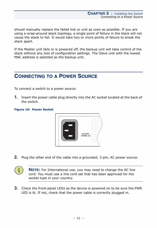
1. Insert the power cable plug directly into the AC socket located at the back of the switch.
Figure 19: Power Socket
2. Plug the other end of the cable into a grounded, 3-pin, AC power source.
3. Check the front-panel LEDs as the device is powered on to be sure the PWR LED is lit. If not, check that the power cable is correctly plugged in.
NOTE: For International use, you may need to change the AC line cord. You must use a line cord set that has been approved for the socket type in your country.
– 51 –
CHAPTER 3 | Installing the SwitchConnecting to the Console Port
4. If you have purchased a Redundant Power Supply, connect it to the switch and to an AC power source now, following the instructions included with the package.
CONNECTING TO THE CONSOLE PORT
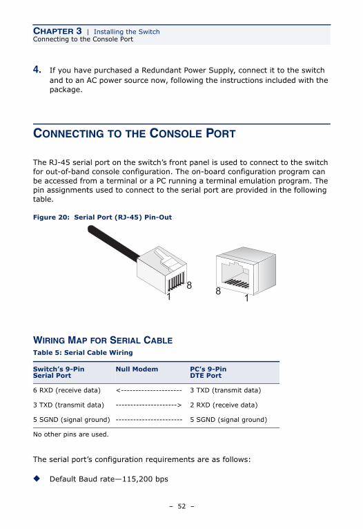
The RJ-45 serial port on the switch’s front panel is used to connect to the switch for out-of-band console configuration. The on-board configuration program can be accessed from a terminal or a PC running a terminal emulation program. The pin assignments used to connect to the serial port are provided in the following table.
Figure 20: Serial Port (RJ-45) Pin-Out
WIRING MAP FOR SERIAL CABLE
The serial port’s configuration requirements are as follows:
◆ Default Baud rate—115,200 bps
Table 5: Serial Cable Wiring
Switch’s 9-Pin Serial Port
Null Modem PC’s 9-Pin DTE Port
6 RXD (receive data) <--------------------- 3 TXD (transmit data)
3 TXD (transmit data) ---------------------> 2 RXD (receive data)
5 SGND (signal ground) ----------------------- 5 SGND (signal ground)
No other pins are used.
811
8
– 52 –

CHAPTER 3 | Installing the SwitchConnecting to the Console Port
◆ Character Size—8 Characters
◆ Parity—None
◆ Stop bit—One
◆ Data bits—8
◆ Flow control—none
– 53 –

CHAPTER 3 | Installing the SwitchConnecting to the Console Port
– 54 –
4 MAKING NETWORK CONNECTIONS
CONNECTING NETWORK DEVICES
This switch is designed to interconnect multiple segments (or collision domains). It can be connected to network cards in PCs and servers, as well as to hubs, switches or routers. It may also be connected to devices using optional XFP or SFP transceivers.
TWISTED-PAIR DEVICES
Each device requires an unshielded twisted-pair (UTP) cable with RJ-45 connectors at both ends. Use Category 5, 5e or 6 cable for 1000BASE-T connections, Category 5 or better for 100BASE-TX connections, and Category 3 or better for 10BASE-T connections.
CABLING GUIDELINESThe RJ-45 ports on the switch support automatic MDI/MDI-X pinout configuration, so you can use standard straight-through twisted-pair cables to connect to any other network device (PCs, servers, switches, routers, or hubs).
See Appendix B for further information on cabling.
CAUTION: Do not plug a phone jack connector into an RJ-45 port. This will damage the switch. Use only twisted-pair cables with RJ-45 connectors that conform to FCC standards.
– 55 –
CHAPTER 4 | Making Network ConnectionsTwisted-Pair Devices
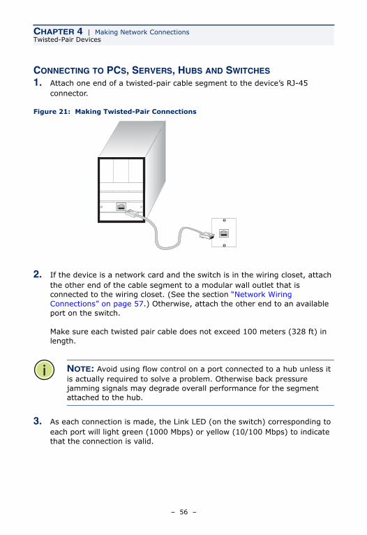
CONNECTING TO PCS, SERVERS, HUBS AND SWITCHES1. Attach one end of a twisted-pair cable segment to the device’s RJ-45
connector.
Figure 21: Making Twisted-Pair Connections
2. If the device is a network card and the switch is in the wiring closet, attach the other end of the cable segment to a modular wall outlet that is connected to the wiring closet. (See the section “Network Wiring Connections” on page 57.) Otherwise, attach the other end to an available port on the switch.
Make sure each twisted pair cable does not exceed 100 meters (328 ft) in length.
3. As each connection is made, the Link LED (on the switch) corresponding to each port will light green (1000 Mbps) or yellow (10/100 Mbps) to indicate that the connection is valid.
NOTE: Avoid using flow control on a port connected to a hub unless it is actually required to solve a problem. Otherwise back pressure jamming signals may degrade overall performance for the segment attached to the hub.
– 56 –
CHAPTER 4 | Making Network ConnectionsTwisted-Pair Devices
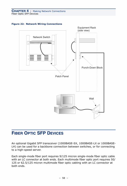
NETWORK WIRING CONNECTIONSToday, the punch-down block is an integral part of many of the newer equipment racks. It is actually part of the patch panel. Instructions for making connections in the wiring closet with this type of equipment follows.
1. Attach one end of a patch cable to an available port on the switch, and the other end to the patch panel.
2. If not already in place, attach one end of a cable segment to the back of the patch panel where the punch-down block is located, and the other end to a modular wall outlet.
3. Label the cables to simplify future troubleshooting. See “Cable Labeling and Connection Records” on page 65.
– 57 –
CHAPTER 4 | Making Network ConnectionsFiber Optic SFP Devices
Figure 22: Network Wiring Connections
FIBER OPTIC SFP DEVICES
An optional Gigabit SFP transceiver (1000BASE-SX, 1000BASE-LX or 1000BASE-LH) can be used for a backbone connection between switches, or for connecting to a high-speed server.
Each single-mode fiber port requires 9/125 micron single-mode fiber optic cable with an LC connector at both ends. Each multimode fiber optic port requires 50/125 or 62.5/125 micron multimode fiber optic cabling with an LC connector at both ends.
Equipment Rack(side view)
Network Switch
Patch Panel
Punch-Down Block
Wall
w it ch 10/1006724L 3
ES4524C
– 58 –
CHAPTER 4 | Making Network ConnectionsFiber Optic SFP Devices
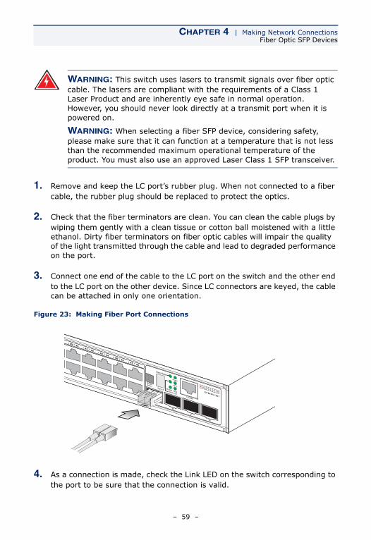
1. Remove and keep the LC port’s rubber plug. When not connected to a fiber cable, the rubber plug should be replaced to protect the optics.
2. Check that the fiber terminators are clean. You can clean the cable plugs by wiping them gently with a clean tissue or cotton ball moistened with a little ethanol. Dirty fiber terminators on fiber optic cables will impair the quality of the light transmitted through the cable and lead to degraded performance on the port.
3. Connect one end of the cable to the LC port on the switch and the other end to the LC port on the other device. Since LC connectors are keyed, the cable can be attached in only one orientation.
Figure 23: Making Fiber Port Connections
4. As a connection is made, check the Link LED on the switch corresponding to the port to be sure that the connection is valid.
WARNING: This switch uses lasers to transmit signals over fiber optic cable. The lasers are compliant with the requirements of a Class 1 Laser Product and are inherently eye safe in normal operation. However, you should never look directly at a transmit port when it is powered on.
WARNING: When selecting a fiber SFP device, considering safety, please make sure that it can function at a temperature that is not less than the recommended maximum operational temperature of the product. You must also use an approved Laser Class 1 SFP transceiver.
– 59 –
CHAPTER 4 | Making Network ConnectionsFiber Optic SFP Devices
The 1000BASE-SX, 1000BASE-LX, 1000BASE-LH fiber optic ports operate at 1 Gbps, full duplex, with auto-negotiation of flow control. The maximum length for fiber optic cable operating at Gigabit speed will depend on the fiber type as listed under “1000 Mbps Gigabit Ethernet Collision Domain” on page 64.
– 60 –
CHAPTER 4 | Making Network Connections10 Gbps Fiber Optic Connections
10 GBPS FIBER OPTIC CONNECTIONS
An optional 10 Gigabit transceiver (XFP) can be used for a backbone connection between switches.
Single-mode fiber ports require 9/125 micron single-mode fiber optic cable. Multimode fiber optic ports require 50/125 or 62.5/125 micron multimode fiber optic cable. Each fiber optic cable must have an LC connector attached at both ends.
1. Remove and keep the port’s protective cover. When not connected to a fiber cable, the cover should be replaced to protect the optics.
2. Check that the fiber terminators are clean. You can clean the cable plugs by wiping them gently with a clean tissue or cotton ball moistened with a little ethanol. Dirty fiber terminators on fiber cables will impair the quality of the light transmitted through the cable and lead to degraded performance on the port.
3. Connect one end of the cable to the LC port on the switch and the other end to the LC port on the other device. Since LC connectors are keyed, the cable can be attached in only one orientation.
WARNING: These switches use lasers to transmit signals over fiber optic cable. The lasers are compliant with the requirements of a Class 1 Laser Product and are inherently eye safe in normal operation. However, you should never look directly at a transmit port when it is powered on.
WARNING: When selecting a fiber device, considering safety, please make sure that it can function at a temperature that is not less than the recommended maximum operational temperature of the product. You must also use an approved Laser Class 1 SFP transceiver.
– 61 –
CHAPTER 4 | Making Network Connections10 Gbps Fiber Optic Connections
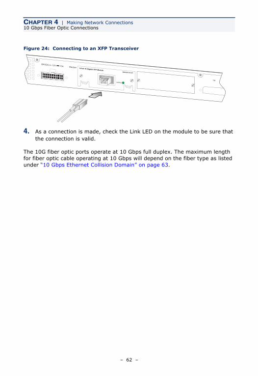
Figure 24: Connecting to an XFP Transceiver
4. As a connection is made, check the Link LED on the module to be sure that the connection is valid.
The 10G fiber optic ports operate at 10 Gbps full duplex. The maximum length for fiber optic cable operating at 10 Gbps will depend on the fiber type as listed under “10 Gbps Ethernet Collision Domain” on page 63.
– 62 –
CHAPTER 4 | Making Network ConnectionsConnectivity Rules
CONNECTIVITY RULES
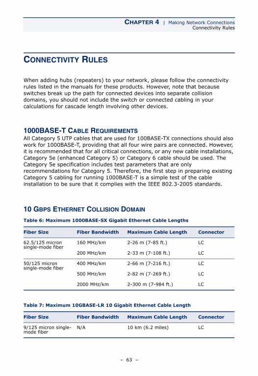
When adding hubs (repeaters) to your network, please follow the connectivity rules listed in the manuals for these products. However, note that because switches break up the path for connected devices into separate collision domains, you should not include the switch or connected cabling in your calculations for cascade length involving other devices.
1000BASE-T CABLE REQUIREMENTSAll Category 5 UTP cables that are used for 100BASE-TX connections should also work for 1000BASE-T, providing that all four wire pairs are connected. However, it is recommended that for all critical connections, or any new cable installations, Category 5e (enhanced Category 5) or Category 6 cable should be used. The Category 5e specification includes test parameters that are only recommendations for Category 5. Therefore, the first step in preparing existing Category 5 cabling for running 1000BASE-T is a simple test of the cable installation to be sure that it complies with the IEEE 802.3-2005 standards.
10 GBPS ETHERNET COLLISION DOMAIN
Table 6: Maximum 1000BASE-SX Gigabit Ethernet Cable Lengths
Fiber Size Fiber Bandwidth Maximum Cable Length Connector
62.5/125 micron single-mode fiber
160 MHz/km 2-26 m (7-85 ft.) LC
200 MHz/km 2-33 m (7-108 ft.) LC
50/125 micron single-mode fiber
400 MHz/km 2-66 m (7-216 ft.) LC
500 MHz/km 2-82 m (7-269 ft.) LC
2000 MHz/km 2-300 m (7-984 ft.) LC
Table 7: Maximum 10GBASE-LR 10 Gigabit Ethernet Cable Length
Fiber Size Fiber Bandwidth Maximum Cable Length Connector
9/125 micron single-mode fiber
N/A 10 km (6.2 miles) LC
– 63 –
CHAPTER 4 | Making Network ConnectionsConnectivity Rules
1000 MBPS GIGABIT ETHERNET COLLISION DOMAIN
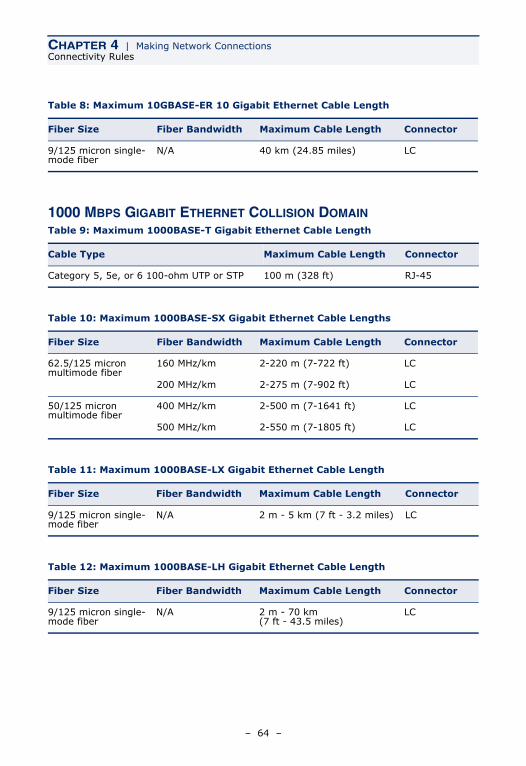
Table 8: Maximum 10GBASE-ER 10 Gigabit Ethernet Cable Length
Fiber Size Fiber Bandwidth Maximum Cable Length Connector
9/125 micron single-mode fiber
N/A 40 km (24.85 miles) LC
Table 9: Maximum 1000BASE-T Gigabit Ethernet Cable Length
Cable Type Maximum Cable Length Connector
Category 5, 5e, or 6 100-ohm UTP or STP 100 m (328 ft) RJ-45
Table 10: Maximum 1000BASE-SX Gigabit Ethernet Cable Lengths
Fiber Size Fiber Bandwidth Maximum Cable Length Connector
62.5/125 micron multimode fiber
160 MHz/km 2-220 m (7-722 ft) LC
200 MHz/km 2-275 m (7-902 ft) LC
50/125 micron multimode fiber
400 MHz/km 2-500 m (7-1641 ft) LC
500 MHz/km 2-550 m (7-1805 ft) LC
Table 11: Maximum 1000BASE-LX Gigabit Ethernet Cable Length
Fiber Size Fiber Bandwidth Maximum Cable Length Connector
9/125 micron single-mode fiber
N/A 2 m - 5 km (7 ft - 3.2 miles) LC
Table 12: Maximum 1000BASE-LH Gigabit Ethernet Cable Length
Fiber Size Fiber Bandwidth Maximum Cable Length Connector
9/125 micron single-mode fiber
N/A 2 m - 70 km (7 ft - 43.5 miles)
LC
– 64 –
CHAPTER 4 | Making Network ConnectionsCable Labeling and Connection Records
100 MBPS FAST ETHERNET COLLISION DOMAIN
10 MBPS ETHERNET COLLISION DOMAIN
CABLE LABELING AND CONNECTION RECORDS
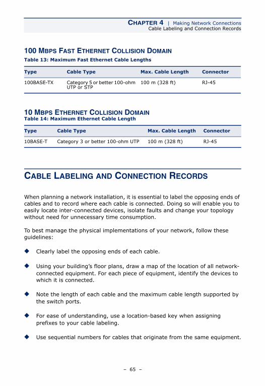
When planning a network installation, it is essential to label the opposing ends of cables and to record where each cable is connected. Doing so will enable you to easily locate inter-connected devices, isolate faults and change your topology without need for unnecessary time consumption.
To best manage the physical implementations of your network, follow these guidelines:
◆ Clearly label the opposing ends of each cable.
◆ Using your building’s floor plans, draw a map of the location of all network-connected equipment. For each piece of equipment, identify the devices to which it is connected.
◆ Note the length of each cable and the maximum cable length supported by the switch ports.
◆ For ease of understanding, use a location-based key when assigning prefixes to your cable labeling.
◆ Use sequential numbers for cables that originate from the same equipment.
Table 13: Maximum Fast Ethernet Cable Lengths
Type Cable Type Max. Cable Length Connector
100BASE-TX Category 5 or better 100-ohm UTP or STP
100 m (328 ft) RJ-45
Table 14: Maximum Ethernet Cable Length
Type Cable Type Max. Cable Length Connector
10BASE-T Category 3 or better 100-ohm UTP 100 m (328 ft) RJ-45
– 65 –
CHAPTER 4 | Making Network ConnectionsCable Labeling and Connection Records
◆ Differentiate between racks by naming accordingly.
◆ Label each separate piece of equipment.
◆ Display a copy of your equipment map, including keys to all abbreviations at each equipment rack.
– 66 –
A TROUBLESHOOTING
DIAGNOSING SWITCH INDICATORS
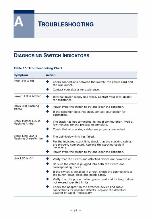
Table 15: Troubleshooting Chart
Symptom Action
PWR LED is Off ◆ Check connections between the switch, the power cord and the wall outlet.
◆ Contact your dealer for assistance.
Power LED is Amber ◆ Internal power supply has failed. Contact your local dealer for assistance.
DIAG LED Flashing Yellow
◆ Power cycle the switch to try and clear the condition.
◆ If the condition does not clear, contact your dealer for assistance.
Stack Master LED is Flashing Amber
◆ The stack has not completed its initial configuration. Wait a few minutes for the process to complete.
◆ Check that all stacking cables are properly connected.
Stack Link LED is Flashing Green/Amber
◆ The uplink/downlink has failed.
◆ For the indicated stack link, check that the stacking cables are properly connected. Replace the stacking cable if necessary.
◆ Power cycle the switch to try and clear the condition.
Link LED is Off ◆ Verify that the switch and attached device are powered on.
◆ Be sure the cable is plugged into both the switch and corresponding device.
◆ If the switch is installed in a rack, check the connections to the punch-down block and patch panel.
◆ Verify that the proper cable type is used and its length does not exceed specified limits.
◆ Check the adapter on the attached device and cable connections for possible defects. Replace the defective adapter or cable if necessary.
– 67 –
CHAPTER A | TroubleshootingDiagnosing Switch Indicators
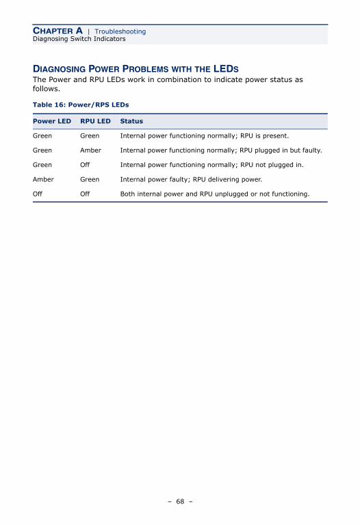
DIAGNOSING POWER PROBLEMS WITH THE LEDSThe Power and RPU LEDs work in combination to indicate power status as follows.
Table 16: Power/RPS LEDs
Power LED RPU LED Status
Green Green Internal power functioning normally; RPU is present.
Green Amber Internal power functioning normally; RPU plugged in but faulty.
Green Off Internal power functioning normally; RPU not plugged in.
Amber Green Internal power faulty; RPU delivering power.
Off Off Both internal power and RPU unplugged or not functioning.
– 68 –
CHAPTER A | TroubleshootingPower and Cooling Problems
POWER AND COOLING PROBLEMS
If the power indicator does not turn on when the power cord is plugged in, you may have a problem with the power outlet, power cord, or internal power supply. However, if the unit powers off after running for a while, check for loose power connections, power losses or surges at the power outlet. If you still cannot isolate the problem, the internal power supply may be defective.
INSTALLATION
Verify that all system components have been properly installed. If one or more components appear to be malfunctioning (such as the power cord or network cabling), test them in an alternate environment where you are sure that all the other components are functioning properly.
IN-BAND ACCESS
You can access the management agent in the switch from anywhere within the attached network using Telnet, a web browser, or other network management software tools. However, you must first configure the switch with a valid IP address, subnet mask, and default gateway. If you have trouble establishing a link to the management agent, check to see if you have a valid network connection. Then verify that you entered the correct IP address. Also, be sure the port through which you are connecting to the switch has not been disabled. If it has not been disabled, then check the network cabling that runs between your remote location and the switch.
NOTE: The management agent accepts up to four simultaneous Telnet sessions. If the maximum number of sessions already exists, an additional Telnet connection will not be able to log into the system.
– 69 –
CHAPTER A | TroubleshootingStack Troubleshooting
STACK TROUBLESHOOTING
If a stack fails to initialize or function, first check the following items:
◆ Check that all stacking cables are properly connected.
◆ Check if any stacking cables appear damaged.
◆ Check that only one Stack Master button is pressed in.
◆ Check that all switches in the stack are powered on.
After checking all items, reboot all the switches in the stack.
Switches in the stack may be configured using a ring- or line-topology. To ensure minimal disruption in case a unit or stacking cable fails, always use a ring-topology. When using ring-topology configuration and a switch fails, or a stacking cable is disconnected, the stack continues normal operation using line-topology stacking through the remaining stack connections.
If any changes occur to a slave unit, such as unit failure or insertion of a new unit, operation of the other units in the stack are not affected. On the other hand, if the master unit fails, the unit with the lowest MAC address is elected as the new master. The stack reboots, discovers the new stack topology, assigns identifiers to each unit, and checks the software images on each unit. This process make take up to two minutes.
If you do not connect a wrap-around cable from the bottom unit back up to the top unit in the stack, the failure of a single unit will cause the stack to break into two separate stacks. In this case, a master unit will be elected for both of the stacks. However, backup information inherited from the previous master unit will cause the same IP address to be used by both master units in the two stacks. You must therefore manually reconfigure the IP address of the management interface on one of the master units.
– 70 –
B CABLES
TWISTED-PAIR CABLE AND PIN ASSIGNMENTS
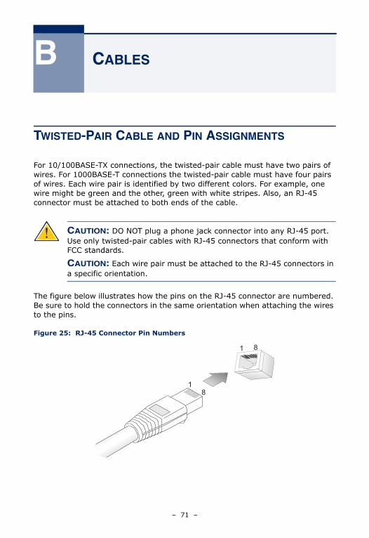
For 10/100BASE-TX connections, the twisted-pair cable must have two pairs of wires. For 1000BASE-T connections the twisted-pair cable must have four pairs of wires. Each wire pair is identified by two different colors. For example, one wire might be green and the other, green with white stripes. Also, an RJ-45 connector must be attached to both ends of the cable.
The figure below illustrates how the pins on the RJ-45 connector are numbered. Be sure to hold the connectors in the same orientation when attaching the wires to the pins.
Figure 25: RJ-45 Connector Pin Numbers
CAUTION: DO NOT plug a phone jack connector into any RJ-45 port. Use only twisted-pair cables with RJ-45 connectors that conform with FCC standards.
CAUTION: Each wire pair must be attached to the RJ-45 connectors in a specific orientation.
81
18
– 71 –
CHAPTER B | CablesTwisted-Pair Cable and Pin Assignments
10BASE-T/100BASE-TX PIN ASSIGNMENTSUse unshielded twisted-pair (UTP) or shielded twisted-pair (STP) cable for RJ-45 connections: 100-ohm Category 3 or better cable for 10 Mbps connections, or 100-ohm Category 5 or better cable for 100 Mbps connections. Also be sure that the length of any twisted-pair connection does not exceed 100 meters (328 feet).
The RJ-45 ports on the switch base unit support automatic MDI/MDI-X operation, so you can use straight-through cables for all network connections to PCs or servers, or to other switches or hubs. In straight-through cable, pins 1, 2, 3, and 6, at one end of the cable, are connected straight through to pins 1, 2, 3, and 6 at the other end of the cable. When using any RJ-45 port on this switch, you can use either straight-through or crossover cable.
Note:The “+” and “-” signs represent the polarity of the wires that make up each wire pair.
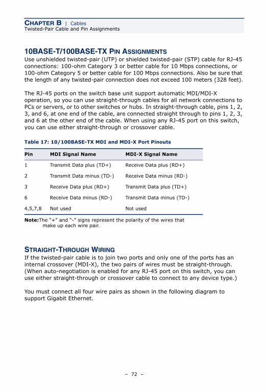
STRAIGHT-THROUGH WIRINGIf the twisted-pair cable is to join two ports and only one of the ports has an internal crossover (MDI-X), the two pairs of wires must be straight-through. (When auto-negotiation is enabled for any RJ-45 port on this switch, you can use either straight-through or crossover cable to connect to any device type.)
You must connect all four wire pairs as shown in the following diagram to support Gigabit Ethernet.
Table 17: 10/100BASE-TX MDI and MDI-X Port Pinouts
Pin MDI Signal Name MDI-X Signal Name
1 Transmit Data plus (TD+) Receive Data plus (RD+)
2 Transmit Data minus (TD-) Receive Data minus (RD-)
3 Receive Data plus (RD+) Transmit Data plus (TD+)
6 Receive Data minus (RD-) Transmit Data minus (TD-)
4,5,7,8 Not used Not used
– 72 –
CHAPTER B | CablesTwisted-Pair Cable and Pin Assignments
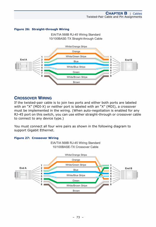
Figure 26: Straight-through Wiring
CROSSOVER WIRINGIf the twisted-pair cable is to join two ports and either both ports are labeled with an “X” (MDI-X) or neither port is labeled with an “X” (MDI), a crossover must be implemented in the wiring. (When auto-negotiation is enabled for any RJ-45 port on this switch, you can use either straight-through or crossover cable to connect to any device type.)
You must connect all four wire pairs as shown in the following diagram to support Gigabit Ethernet.
Figure 27: Crossover Wiring
White/Orange Stripe
Orange
White/Green Stripe
Green
1
2
3
4
5
6
7
8
1
2
3
4
5
6
7
8
EIA/TIA 568B RJ-45 Wiring Standard
10/100BASE-TX Straight-through Cable
End A End BBlue
White/Blue Stripe
Brown
White/Brown Stripe
White/Orange Stripe
Orange
White/Green Stripe1
2
3
4
5
6
7
8
1
2
3
4
5
6
7
8
EIA/TIA 568B RJ-45 Wiring Standard
10/100BASE-TX Crossover Cable
End A End B
Green
Blue
White/Blue Stripe
Brown
White/Brown Stripe
– 73 –
CHAPTER B | CablesTwisted-Pair Cable and Pin Assignments
1000BASE-T PIN ASSIGNMENTSAll 1000BASE-T ports support automatic MDI/MDI-X operation, so you can use straight-through cables for all network connections to PCs or servers, or to other switches or hubs.
The table below shows the 1000BASE-T MDI and MDI-X port pinouts. These ports require that all four pairs of wires be connected. Note that for 1000BASE-T operation, all four pairs of wires are used for both transmit and receive.
Use 100-ohm Category 5, 5e or 6 unshielded twisted-pair (UTP) or shielded twisted-pair (STP) cable for 1000BASE-T connections. Also be sure that the length of any twisted-pair connection does not exceed 100 meters (328 feet).
CABLE TESTING FOR EXISTING CATEGORY 5 CABLE
Installed Category 5 cabling must pass tests for Attenuation, Near-End Crosstalk (NEXT), and Far-End Crosstalk (FEXT). This cable testing information is specified in the ANSI/TIA/EIA-TSB-67 standard. Additionally, cables must also pass test parameters for Return Loss and Equal-Level Far-End Crosstalk (ELFEXT). These tests are specified in the ANSI/TIA/EIA-TSB-95 Bulletin, “The Additional Transmission Performance Guidelines for 100 Ohm 4-Pair Category 5 Cabling.”
Note that when testing your cable installation, be sure to include all patch cables between switches and end devices.
Table 18: 1000BASE-T MDI and MDI-X Port Pinouts
Pin MDI Signal Name MDI-X Signal Name
1 Bi-directional Pair A Plus (BI_DA+) Bi-directional Pair B Plus (BI_DB+)
2 Bi-directional Pair A Minus (BI_DA-) Bi-directional Pair B Minus (BI_DB-)
3 Bi-directional Pair B Plus (BI_DB+) Bi-directional Pair A Plus (BI_DA+)
4 Bi-directional Pair C Plus (BI_DC+) Bi-directional Pair D Plus (BI_DD+)
5 Bi-directional Pair C Minus (BI_DC-) Bi-directional Pair D Minus (BI_DD-)
6 Bi-directional Pair B Minus (BI_DB-) Bi-directional Pair A Minus (BI_DA-)
7 Bi-directional Pair D Plus (BI_DD+) Bi-directional Pair C Plus (BI_DC+)
8 Bi-directional Pair D Minus (BI_DD-) Bi-directional Pair C Minus (BI_DC-)
– 74 –
CHAPTER B | CablesFiber Standards
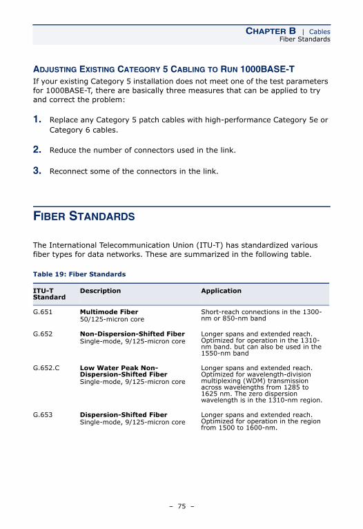
ADJUSTING EXISTING CATEGORY 5 CABLING TO RUN 1000BASE-TIf your existing Category 5 installation does not meet one of the test parameters for 1000BASE-T, there are basically three measures that can be applied to try and correct the problem:
1. Replace any Category 5 patch cables with high-performance Category 5e or Category 6 cables.
2. Reduce the number of connectors used in the link.
3. Reconnect some of the connectors in the link.
FIBER STANDARDS
The International Telecommunication Union (ITU-T) has standardized various fiber types for data networks. These are summarized in the following table.
Table 19: Fiber Standards
ITU-T Standard
Description Application
G.651 Multimode Fiber50/125-micron core
Short-reach connections in the 1300-nm or 850-nm band
G.652 Non-Dispersion-Shifted FiberSingle-mode, 9/125-micron core
Longer spans and extended reach. Optimized for operation in the 1310-nm band. but can also be used in the 1550-nm band
G.652.C Low Water Peak Non-Dispersion-Shifted FiberSingle-mode, 9/125-micron core
Longer spans and extended reach. Optimized for wavelength-division multiplexing (WDM) transmission across wavelengths from 1285 to 1625 nm. The zero dispersion wavelength is in the 1310-nm region.
G.653 Dispersion-Shifted FiberSingle-mode, 9/125-micron core
Longer spans and extended reach. Optimized for operation in the region from 1500 to 1600-nm.
– 75 –

CHAPTER B | CablesFiber Standards
G.654 1550-nm Loss-Minimized FiberSingle-mode, 9/125-micron core
Extended long-haul applications. Optimized for high-power transmission in the 1500 to 1600-nm region, with low loss in the 1550-nm band.
G.655 Non-Zero Dispersion-Shifted FiberSingle-mode, 9/125-micron core
Extended long-haul applications. Optimized for high-power dense wavelength-division multiplexing (DWDM) operation in the region from 1500 to 1600-nm.
Table 19: Fiber Standards (Continued)
ITU-T Standard
Description Application
– 76 –
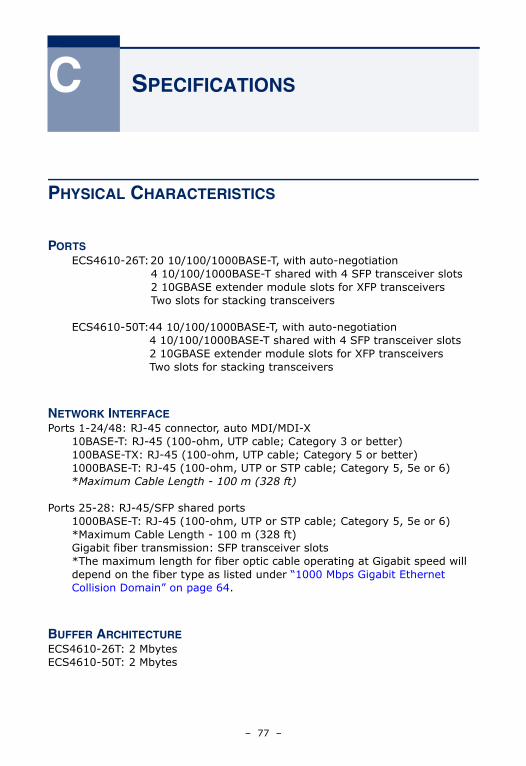
C SPECIFICATIONS
PHYSICAL CHARACTERISTICS
PORTSECS4610-26T:20 10/100/1000BASE-T, with auto-negotiation
4 10/100/1000BASE-T shared with 4 SFP transceiver slots2 10GBASE extender module slots for XFP transceiversTwo slots for stacking transceivers
ECS4610-50T:44 10/100/1000BASE-T, with auto-negotiation4 10/100/1000BASE-T shared with 4 SFP transceiver slots2 10GBASE extender module slots for XFP transceiversTwo slots for stacking transceivers
NETWORK INTERFACEPorts 1-24/48: RJ-45 connector, auto MDI/MDI-X
10BASE-T: RJ-45 (100-ohm, UTP cable; Category 3 or better)100BASE-TX: RJ-45 (100-ohm, UTP cable; Category 5 or better)1000BASE-T: RJ-45 (100-ohm, UTP or STP cable; Category 5, 5e or 6)*Maximum Cable Length - 100 m (328 ft)
Ports 25-28: RJ-45/SFP shared ports1000BASE-T: RJ-45 (100-ohm, UTP or STP cable; Category 5, 5e or 6)*Maximum Cable Length - 100 m (328 ft)Gigabit fiber transmission: SFP transceiver slots*The maximum length for fiber optic cable operating at Gigabit speed will depend on the fiber type as listed under “1000 Mbps Gigabit Ethernet Collision Domain” on page 64.
BUFFER ARCHITECTUREECS4610-26T: 2 MbytesECS4610-50T: 2 Mbytes
– 77 –
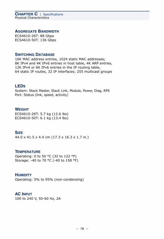
CHAPTER C | SpecificationsPhysical Characteristics
AGGREGATE BANDWIDTHECS4610-26T: 88 GbpsECS4610-50T: 136 Gbps
SWITCHING DATABASE16K MAC address entries, 1024 static MAC addresses; 8K IPv4 and 4K IPv6 entries in host table, 4K ARP entries, 12K IPv4 or 6K IPv6 entries in the IP routing table,64 static IP routes, 32 IP interfaces; 255 multicast groups
LEDS System: Stack Master, Stack Link, Module, Power, Diag, RPS Port: Status (link, speed, activity)
WEIGHTECS4610-26T: 5.7 kg (12.6 lbs)ECS4610-50T: 6.1 kg (13.4 lbs)
SIZE44.0 x 41.5 x 4.4 cm (17.3 x 16.3 x 1.7 in.)
TEMPERATUREOperating: 0 to 50 °C (32 to 122 °F)Storage: -40 to 70 °C (-40 to 158 °F)
HUMIDITYOperating: 5% to 95% (non-condensing)
AC INPUT100 to 240 V, 50-60 Hz, 2A
– 78 –
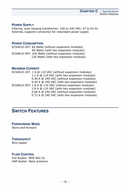
CHAPTER C | SpecificationsSwitch Features
POWER SUPPLYInternal, auto-ranging transformer: 100 to 240 VAC, 47 to 63 HzExternal, supports connection for redundant power supply
POWER CONSUMPTIONECS4610-26T: 66 Watts (without expansion modules)
80 Watts (with two expansion modules)ECS4610-50T: 100 Watts (without expansion modules)
130 Watts (with two expansion modules)
MAXIMUM CURRENTECS4610-26T: 1 A @ 110 VAC (without expansion modules)
1.1 A @ 110 VAC (with two expansion modules) 0.38 A @ 240 VAC (without expansion modules) 0.44 A @ 240 VAC (with two expansion modules)
ECS4610-50T: 1.6 A @ 110 VAC (without expansion modules) 1.8 A @ 110 VAC (with two expansion modules) 0.66 A @ 240 VAC (without expansion modules) 0.72 A @ 240 VAC (with two expansion modules)
SWITCH FEATURES
FORWARDING MODEStore-and-forward
THROUGHPUTWire speed
FLOW CONTROLFull-duplex: IEEE 802.3xHalf-duplex: Back pressure
– 79 –
CHAPTER C | SpecificationsManagement Features
MANAGEMENT FEATURES
IN-BAND MANAGEMENTSSH, Telnet, SNMP, or HTTP
OUT-OF-BAND MANAGEMENTRS-232 DB-9 console port
SOFTWARE LOADINGTFTP in-band, or XModem out-of-band
STANDARDS
IEEE 802.3-2005 Ethernet, Fast Ethernet, Gigabit EthernetFull-duplex flow control
IEEE 802.3ae 10 Gigabit EthernetIEEE 802.1D Spanning Tree ProtocolIEEE 802.1w Rapid Spanning Tree ProtocolIEEE 802.1s Multiple Spanning Tree ProtocolIEEE 802.1Q Virtual LANISO/IEC 8802-3 CSMA/CD
– 80 –
CHAPTER C | SpecificationsCompliances
COMPLIANCES
CE MARK
EMISSIONSFCC Class AIndustry Canada Class AEN55022 (CISPR 22) Class AEN 61000-3-2/3VCCI Class AC-Tick - AS/NZS 3548 (1995) Class A
IMMUNITYEN 61000-4-2/3/4/5/6/8/11
SAFETYUL 60950-1 & CSA 60950-1IEC 60950-1 & EN 60950-1
10GBASE EXTENDER MODULE (XFP)
PORTS1 slot for 10GBASE XFP transceiver
COMMUNICATION SPEED10 Gbps
COMMUNICATION MODEFull duplex
– 81 –

CHAPTER C | Specifications10GBASE Extender Module (XFP)
NETWORK INTERFACEXFP slot
STANDARDSIEEE 802.3ae 10 Gigabit Ethernet
– 82 –
GLOSSARY
10BASE-TIEEE 802.3 specification for 10 Mbps Ethernet over two pairs of Category 3, 4, or 5 UTP cable.
100BASE-TXIEEE 802.3u specification for 100 Mbps Ethernet over two pairs of Category 5 UTP cable.
1000BASE-LHSpecification for long-haul Gigabit Ethernet over two strands of 9/125 micron core fiber cable.
1000BASE-LXIEEE 802.3z specification for Gigabit Ethernet over two strands of 50/125, 62.5/125 or 9/125 micron core fiber cable.
1000BASE-SXIEEE 802.3z specification for Gigabit Ethernet over two strands of 50/125 or 62.5/125 micron core fiber cable.
1000BASE-TIEEE 802.3ab specification for Gigabit Ethernet over 100-ohm Category 5, 5e or 6 twisted-pair cable (using all four wire pairs).
10GBASE-ERIEEE 802.3ae specification for 10 Gigabit Ethernet over two strands of 9/125 micron core single-mode fiber cable.
– 83 –
GLOSSARY
10GBASE-LRIEEE 802.3ae specification for 10 Gigabit Ethernet over two strands of 9/125 micron core single-mode fiber cable.
10GBASE-SRIEEE 802.3ae specification for 10 Gigabit Ethernet over two strands of 62.5/125 micron core multimode fiber cable.
10 GIGABIT ETHERNETA 10 Gbps network communication system based on Ethernet.
AUTO-NEGOTIATIONSignalling method allowing each node to select its optimum operational mode (e.g., speed and duplex mode) based on the capabilities of the node to which it is connected.
BANDWIDTHThe difference between the highest and lowest frequencies available for network signals. Also synonymous with wire speed, the actual speed of the data transmission along the cable.
COLLISION DOMAINSingle CSMA/CD LAN segment.
CSMA/CDCSMA/CD (Carrier Sense Multiple Access/Collision Detect) is the communication method employed by Ethernet, Fast Ethernet, and Gigabit Ethernet.
END STATIONA workstation, server, or other device that does not forward traffic.
– 84 –
GLOSSARY
ETHERNETA network communication system developed and standardized by DEC, Intel, and Xerox, using baseband transmission, CSMA/CD access, logical bus topology, and coaxial cable. The successor IEEE 802.3 standard provides for integration into the OSI model and extends the physical layer and media with repeaters and implementations that operate on fiber, thin coax and twisted-pair cable.
FAST ETHERNETA 100 Mbps network communication system based on Ethernet and the CSMA/CD access method.
FULL-DUPLEXTransmission method that allows two network devices to transmit and receive concurrently, effectively doubling the bandwidth of that link.
GIGABIT ETHERNETA 1000 Mbps network communication system based on Ethernet and the CSMA/CD access method.
IEEEInstitute of Electrical and Electronic Engineers.
IEEE 802.3Defines carrier sense multiple access with collision detection (CSMA/CD) access method and physical layer specifications.
IEEE 802.3ABDefines CSMA/CD access method and physical layer specifications for 1000BASE-T Gigabit Ethernet. (Now incorporated in IEEE 802.3-2005.)
IEEE 802.3AEDefines the physical layer specifications for 10 Gigabit Ethernet.
– 85 –
GLOSSARY
IEEE 802.3UDefines CSMA/CD access method and physical layer specifications for 100BASE-TX Fast Ethernet. (Now incorporated in IEEE 802.3-2005.)
IEEE 802.3ZDefines CSMA/CD access method and physical layer specifications for 1000BASE Gigabit Ethernet. (Now incorporated in IEEE 802.3-2005.)
LAN SEGMENTSeparate LAN or collision domain.
LEDLight emitting diode used for monitoring a device or network condition.
LOCAL AREA NETWORK (LAN) A group of interconnected computer and support devices.
MEDIA ACCESS CONTROL (MAC)A portion of the networking protocol that governs access to the transmission medium, facilitating the exchange of data between network nodes.
MIBAn acronym for Management Information Base. It is a set of database objects that contains information about the device.
MODAL BANDWIDTHBandwidth for multimode fiber is referred to as modal bandwidth because it varies with the modal field (or core diameter) of the fiber. Modal bandwidth is specified in units of MHz per km, which indicates the amount of bandwidth supported by the fiber for a one km distance.
– 86 –
GLOSSARY
NETWORK DIAMETERWire distance between two end stations in the same collision domain.
REDUNDANT POWER SUPPLY (RPS)A backup power supply unit that automatically takes over in case the primary power supply should fail.
RJ-45 CONNECTORA connector for twisted-pair wiring.
SWITCHED PORTSPorts that are on separate collision domains or LAN segments.
TIATelecommunications Industry Association
TRANSMISSION CONTROL PROTOCOL/INTERNET PROTOCOL (TCP/IP)Protocol suite that includes TCP as the primary transport protocol, and IP as the network layer protocol.
UTPUnshielded twisted-pair cable.
VIRTUAL LAN (VLAN)A Virtual LAN is a collection of network nodes that share the same collision domain regardless of their physical location or connection point in the network. A VLAN serves as a logical workgroup with no physical barriers, allowing users to share information and resources as though located on the same LAN.
– 87 –

GLOSSARY
– 88 –
INDEX
NUMERICS10 Gbps connectivity rules 6310 Mbps connectivity rules 65100 Mbps connectivity rules 651000 Mbps connectivity rules 641000BASE-LH fiber cable Lengths 641000BASE-LX fiber cable Lengths 641000BASE-SX fiber cable Lengths 63, 641000BASE-T
pin assignments 74100BASE-TX, cable lengths 6510BASE-T, cable lengths 65
Aadhesive feet, attaching 46applications
central wiring closet 35collapsed backbone 34Layer 3 routing 38remote connections with fiber 36VLAN connections 37
Bbrackets, attaching 45buffer size 77
Ccable
Ethernet cable compatibility 42fiber standards 75labeling and connection records 65lengths 63, 65
cleaning fiber terminators 59, 61compliances
EMC 81safety 81
connectivity rules10 Gbps 6310 Mbps 65100 Mbps 651000 Mbps 64
console port, pin assignments 52contents of package 43cooling problems 69cord sets, international 51
Ddesktop mounting 46
Eelectrical interference, avoiding 41equipment checklist 43Ethernet connectivity rules 63, 65
FFast Ethernet connectivity rules 65features 80
management 31switch 30
front panel of switch 24
GGigabit Ethernet cable lengths 64grounding for racks 44
IIEEE 802.3 Ethernet 30IEEE 802.3ae 10 Gigabit Ethernet 30IEEE 802.3u Fast Ethernet 30IEEE 802.3z Gigabit Ethernet 30indicators, LED 26installation
connecting devices to the switch 56desktop or shelf mounting 46network wiring connections 57port connections 55, 58power requirements 41problems 69rack mounting 44site requirements 41
Llaser safety 59, 61LC port connections 58, 61
– 89 –
INDEX
LED indicatorsDIAG 27Module 28PWR 27Stack ID 28Stack Link 28Stack Master 27
location requirements 41
Mmanagement
agent 25features 31, 80SNMP 25
mounting the switchin a rack 44on a desktop or shelf 46
Nnetwork
connections 55, 58examples 34
Ooptional modules, installation 47
Ppackage contents 43pin assignments 71
1000BASE-T 7410BASE-T/100BASE-TX 72console port 52
ports, connecting to 55, 58power, connecting to 51
Rrack mounting 44rear panel of switch 24RJ-45 port
connections 55pinouts 74
rubber foot pads, attaching 46
Sscrews for rack mounting 43SFP transceiver slots 25site selelction 41SNMP agent 25
specificationscompliances 81environmental 78power 79
standardscompliance 81IEEE 80
status LEDs 26switch architecture 24
TTelnet 69temperature within a rack 44troubleshooting
in-band access 69power and cooling problems 69
twisted-pair connections 55
VVLANs
routing 38VLANS, tagging 37
– 90 –


ECS4610-26TECS4610-50T
E052010-MW-R01150200000149A