Embed Size (px)
Citation preview
EE 486 Power Electronics Final Exam Coverage
Prof. Ali Mehrizi-Sani [email protected]
School of Electrical Engineering and Computer Science
April 26, 2012
2 of 18
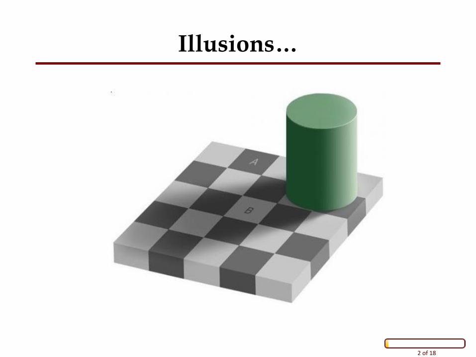
Illusions…
3 of 18
Final Exam Coverage
All Material Covered During Semester – Closed book, no notes.
– Nontrivial equations will be provided if required.
Textbook (Daniel Hart)
Course Notes – Course notes and the text complement each other. There are material
covered in lectures that are not in the text.
Homeworks – All solutions are posted (Homework 10 solution will be posted on Wed).
– Homeworks are marked and returned.
As a reminder, you have access to all material from 2012, including tests, exams, homeworks, and their solutions.
4 of 18
Chapters 1 and 2: Review
Introductory Slides
Basic Concepts – Linear voltage regulator vs. switched-mode converters
– Efficiency
– Real, reactive, and complex power
– Average and instantaneous power
– Fourier series (equations will be given)
– RMS and average value calculation
5 of 18
Chapter 6: DC-DC Converters
Sections 6.1, .2, .3, .5, .6, .7, .8, .10, and .11
IVSB <vL(t)> = 0
CCB <iC(t)> = 0
SRA iL(t) = IL , vC(t) = VC
Calculating ΔIL and ΔVC
Calculating M(D)
Drawing Steady-State Waveforms – Buck
– Boost
– Buck-Boost
– All other topologies
6 of 18
Chapter 6: Nonideal DC-DC Converters
Nonideal Voltage Conversion Ratio – RL
– RON
– RD and VD
– ESR, rc
– VI characteristic for different power electronics elements: diode and MOSFET/IGBT/BJT
7 of 18
Chapter 6: Discontinuous Conduction
Boundary of CCM and DCM
Calculation of M(D) in DCM
Applying IVSB and CCB for Three Operating States – Q on, D off
– Q off, D on
– Q off, D off
Small Ripple Approximation – If DCM is because of inductor (diode) current, SRA is not valid for
IL, but is still valid for VC
8 of 18
Steps for Solving a Converter
Draw subcircuits for subintervals 0 < t ≤ DT and DT < t ≤ T
Determine vL(t) (or vL,i(t) if there are multiple inductors) and iC (t) (or iC,i (t) if there are multiple capacitors) for each subinterval – Write vL,i (t) in terms of capacitors (and output) and input voltage
– Write iC (t) in terms of inductor currents
Apply IVSB to each vL,i (t) and CCB to each iC,i (t)
Simplify and solve for Vo in terms of Vs
9 of 18
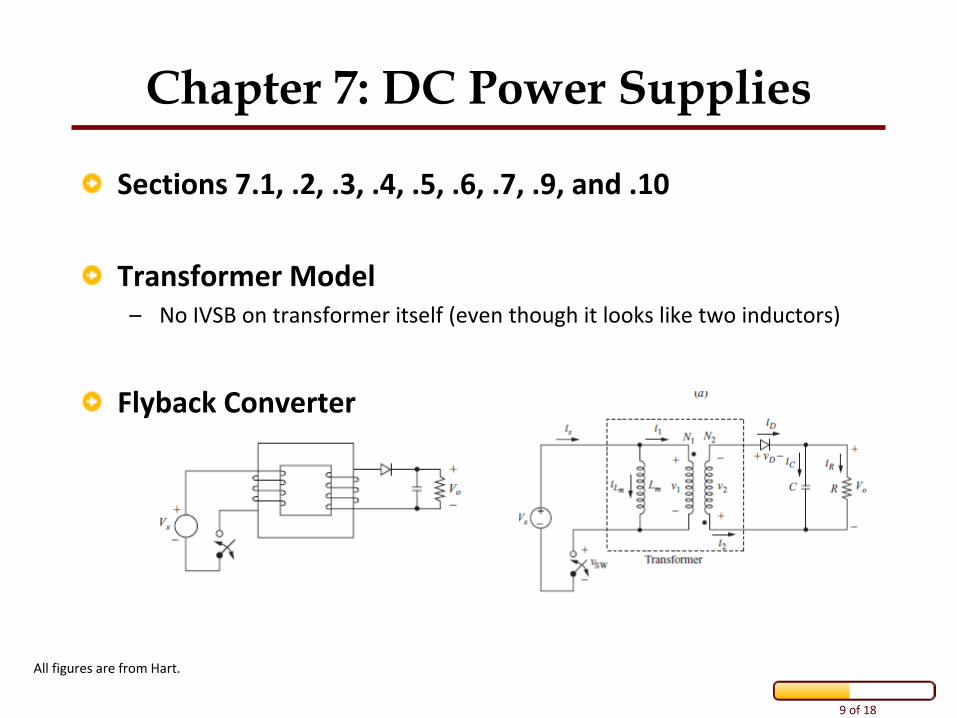
Chapter 7: DC Power Supplies
Sections 7.1, .2, .3, .4, .5, .6, .7, .9, and .10
Transformer Model – No IVSB on transformer itself (even though it looks like two inductors)
Flyback Converter
All figures are from Hart.
10 of 18
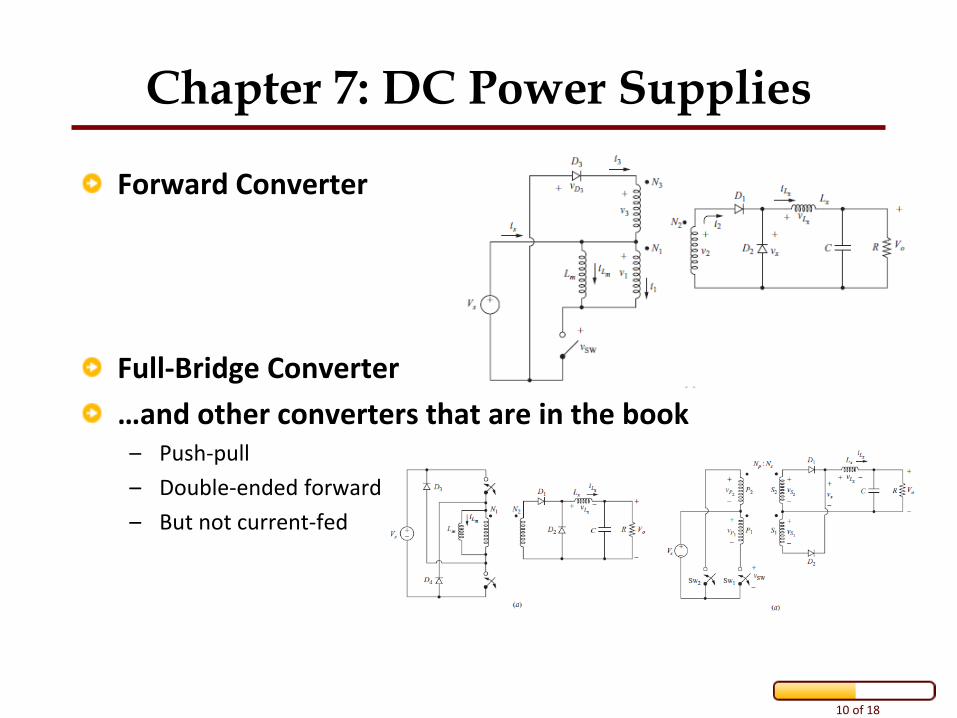
Chapter 7: DC Power Supplies
Forward Converter
Full-Bridge Converter
…and other converters that are in the book – Push-pull
– Double-ended forward
– But not current-fed
11 of 18
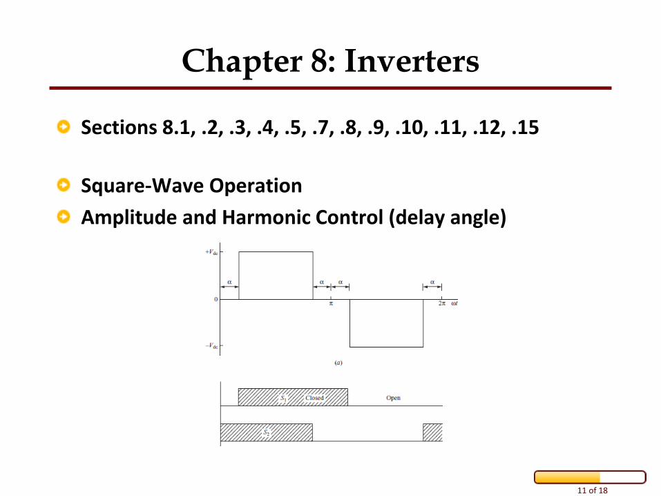
Chapter 8: Inverters
Sections 8.1, .2, .3, .4, .5, .7, .8, .9, .10, .11, .12, .15
Square-Wave Operation
Amplitude and Harmonic Control (delay angle)
12 of 18
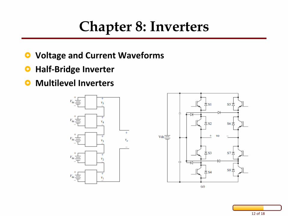
Chapter 8: Inverters
Voltage and Current Waveforms
Half-Bridge Inverter
Multilevel Inverters
13 of 18
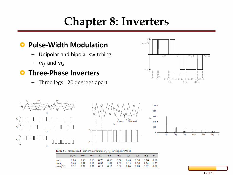
Chapter 8: Inverters
Pulse-Width Modulation
– Unipolar and bipolar switching
– mf and ma
Three-Phase Inverters – Three legs 120 degrees apart
14 of 18
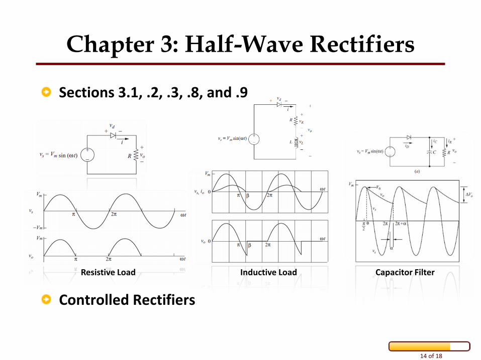
Chapter 3: Half-Wave Rectifiers
Sections 3.1, .2, .3, .8, and .9
Controlled Rectifiers
Resistive Load Inductive Load Capacitor Filter
15 of 18
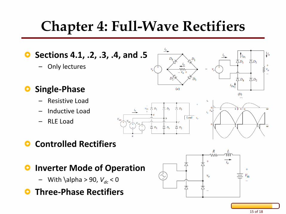
Chapter 4: Full-Wave Rectifiers
Sections 4.1, .2, .3, .4, and .5 – Only lectures
Single-Phase – Resistive Load
– Inductive Load
– RLE Load
Controlled Rectifiers
Inverter Mode of Operation – With \alpha > 90, Vdc < 0
Three-Phase Rectifiers
16 of 18
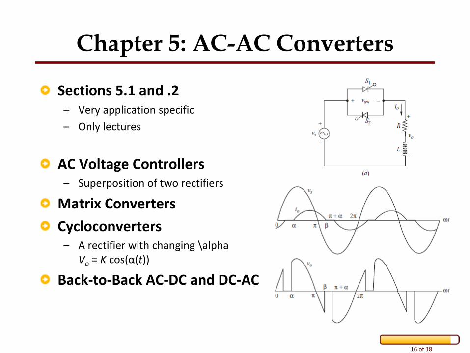
Chapter 5: AC-AC Converters
Sections 5.1 and .2 – Very application specific
– Only lectures
AC Voltage Controllers – Superposition of two rectifiers
Matrix Converters
Cycloconverters – A rectifier with changing \alpha
Vo = K cos(α(t))
Back-to-Back AC-DC and DC-AC
17 of 18
Bigger Picture
Buck-boost--ness is in the eye of the beholder.
An inverter (DC-AC) is essentially a DC-DC converter with slowly varying duty cycle. – Variations of d(t) much slower than the switching frequency
An AC voltage controller (AC-AC) is essentially a rectifier with slowly varying delay angle α. – Variations of α(t) much slower than input frequency
Ultimately, DC-DC and AC-AC can be thought of as controllable transformers. – Can change effective resistance (impedance) seen by the source (utility)
18 of 18
Good Luck
See you in EE525!
Questions later? – Email: [email protected]
– In Person: EME 35