Embed Size (px)
Citation preview

A801 A802
ボー
ルね
じBall Scresw볼스크류
Ball Scresw볼스크류
기술해설
Technical description
ボー
ルね
じBall Scresw볼스크류
Ball Scresw볼스크류
기술해설
Technical description
볼스크류의 구조Construction of Ball Screws
그림 A-81 : 기기효율Fig. A-81 : Mechanical Efficiency
볼스크류 기술해설 Ball Screw Technical Description볼나사의 특징Feature of Ball Screws
●높은 기기 효율KSS 볼스크류는 나사축과 너트 사이에 강구를 삽입한 구름 접촉을 하고 있으므로 일반적으로 90% 정도의 높은 기기 효율을 가지고 있으며 종래의 이송 나사와 비교해서 요소 토크는 1/3 이하입니다. 또한 직선 운동도 쉽게 회전 운동으로(역작동) 변환할 수 있습니다.(그림 A-81)。
●리턴 플레이트 타입 Return-plate system리턴 플레이트 타입은 너트 내부에 설치된 코일 타입의 디플렉터에 따라 강구를 주워 올려, 리턴 플레이트의 홈에 따라서 순환합니다. 리턴 튜브 타입과 비교하면 너트의 샤프트 외경을 작게 할수 있는 장점이 있습니다. 구조상 리턴 플레이트의 부분이 위처럼 되도록 장치에 설치하면 보다 원활한 회전을 얻을수 있습니다.
The Return-plate system uses coil-type deflectors incorporated inside the Nut to pick up the steel Balls and circulate them via the Return-plate channel. This system has the advantage of allowing the use of a Nut that is smaller in diameter than those employed in Return-tube systems. In addition, the upward-angle installation of the Return-plate ensures even smoother rotation.
●엔드 캡 타입 End-cap system엔드 캡 타입은 강구가 나사축과 너트의 홈 사이를 미끌어가면서 나아가 너트 양끝에 설치된 순환부품(엔드 캡)의 통로에서 너트에 설치된 관통 홀을 통해 원래 자리로 돌아오는 순환방식입니다.
The End-cap system is a recirculating system in which the Balls advance by rolling through the screw groove between the Nut and the Screw Shaft. The Balls are then returned via the holes in the Nut and the channels in the recirculating sections of the End-caps on either end of the Nut.
●리턴 튜브 타입 Return-tube system나사축과 너트 사이를 회전하고 있는 강구가 너트에 삽입한 리턴 튜브의 선단에 따라 나사 홈에서부터 빼내어, 튜브의 중심을 통해 다시 나사 홈으로 돌아가는 순환방식입니다.
In the Return-tube system, Balls rolling between the Nut and the Shaft are picked up from the screw groove by the end of the Return-tube built into the Nut. Then, they flow back through the Return-tube to the screw groove.
●코마식 Internal-deflector system코마식은 가능한 한 너트 외경, 너트 길이를 컴팩트하게 경량화 시킨 미니츄어 볼스크류입니다. 나사축 및 너트에 설치된 볼 전동홈을 강구가 축방향 하중을 받으면서 구름운동을 하고, 너트 내부에 심어진 코마 홈을 따라 옆의 전동 홈으로 이동하며 다시 하중 영역으로 돌아와 무한 구름운동을 합니다.
The Internal-deflector system employs a lightweight Miniature Ball Screw, which enables the Nut diameter and length to be reduced to the smallest possible size. The Balls bear the load while rolling along the screw groove between the Shaft and the Nut. The Balls are continuously circulated, transferred to the adjacent groove in the screw via the Internal-deflector channel and then back to the loaded groove area.
●엔드 디플렉터 타입 End-deflector system너트 내부 또는 외부에 설치된 엔드 디플렉터로부터 너트 관통 홀을 통해 원래에 홈에 순환하는 방식입니다.리턴 플레이트 타입과 비교하면 샤프트 외경이 콤팩트로 설계되어 있습니다.중 리드에 최적의 순환방식입니다.
The Balls are circulated from End-deflector incorporated inside the Nut or outside the Nut through the hole in the Nut and the channels in the recirculating sections. Ball Nut diameter can be smaller than Return-plate system. This is suitable for the middle lead Ball Screws.
●나사홈 형상볼스크류에는 하나의 원호로 형성된 서큘러 아크와 두개의 원호로 형성된 고딕 아크 등 두가지 종류가 있습니다, KSS 볼스크류는 고딕 아크를 채용하고 있습니다.
Ball screws may have either a circular arc profile, formed of a single arc, or a gothic arc profile, formed from two arcs.KSS Ball Screws feature a gothic arc profile.
●축방향 유격종래의 삼각 나사나 사다리꼴 나사 등은 축방향 유격을 작 게 하 면 미 끄 럼 마 찰 에 의 하 여 회 전 토 크 가 무거워집니다. KSS 볼스크류는 축방향 유격을 제로로 한 상태에도 매우 가볍게 회전할 수 있습니다. 또한 더블 너트를 사용함으로서 강도를 높일 수도 있습니다.
●고정도KSS 볼스크류는 항온에서 온도 관리를 한 공장에서 초정밀 이송 나사 및 나사 게이지의 가공 기술을 사용하여 가공, 조립, 검사를 하고있습니다. 정밀도가 높고 정확한 위치 결정에 높은 신뢰성을 대비하고 있습니다.
●긴 수명볼스크류의 작동은 적절한 재료에 열처리를 더하여 생산된 구름 접촉 운동에 의하여 마찰 저항력은 극히 작으며 거의 마찰이 일어나지 않기에 장시간을 걸쳐도 고정밀도를 유지할수 있습니다.
●High mechanical efficiencyKSS Ball Screws are fitted with steel Balls, providing rolling contact between the Nut and Screw Shaft, allowing for mechanical efficiency of about 90% and reducing the required Torque to less than one-third that of conventional Lead Screws. The design of the KSS Ball Screws also allows linear motion to be converted into rotary motion easily (Fig. A-81).
●Axial playWith conventional Triangular and Trapezoidal Screw threads, reducing the Axial play increases the rotational Torque due to the sliding friction.KSS Ball Screws, on the other hand, are very easily rotated, even with no Axial play. The use of Double Nuts also provides increased Rigidity.
●High precisionKSS Ball Screws are machined, assembled, and inspected using the technology of ultra-precision Lead Screw and Screw Gauge machining, under the temperature controlled room. High precision and accurate positioning ensure high reliability in use.
●Long service lifeThe Ball Screw movement results in virtually no wear, as the rolling-contact design, combined with the use of carefully selected heat-treated materials, results in an extremely low friction. This is the reason that high precision can be kept over long period.
Forw
ard
Effic
ienc
y:정
효율(
%)
Forward Efficiency(정효율)μ=0.005μ=0.003
μ=0.010
μ=0.1
μ=0.2
Lead Screw(미끄럼 나사)
μ:Friction Coefficient(마찰계수)
Ball Screw(볼스크류)
0
10
20
30
40
50
60
70
80
90
100
0 2 4 6 8 10 12 14 16 18 20Lead Angle:리드각(deg)
0
10
20
30
40
50
60
70
80
90
100
0 2 4 6 8 10 12 14 16 18 20
Bac
kwar
d Ef
ficie
ncy:
역효
율(
%)
Lead Angle:리드각(deg)
Backward Efficiency(역효율)μ=0.005μ=0.003
μ=0.010
μ=0.1
μ=0.2
Lead Screw(미끄럼 나사)
Ball Screw(볼스크류)
μ:Friction Coefficient(마찰계수)
Nut(너트)Shaft(나사축)Spring deflector
(디플렉터)
Balls(강구)
Nut(너트)
Balls(강구)
Internal-deflector(틈)
Shaft(나사축)
Shaft(나사축)
End-Cap(엔드 캡)
Nut(너트)
Balls(강구)Shaft(나사축)
End-deflector(엔드 디플렉터)Nut(너트)
Balls(강구)
Shaft(나사축)
Return-tube(리턴 튜브)
Nut(너트)
R R R
Round groove(서큘러 아크)
Gothic arc groove(고딕 아크)
Return-plate(리턴 플레이트)

A803 A804
ボー
ルね
じBall Scresw볼스크류
Ball Scresw볼스크류
기술해설
Technical description
ボー
ルね
じBall Scresw볼스크류
Ball Scresw볼스크류
기술해설
Technical description
볼스크류의 제작범위The range of manufacturing for Ball Screws
볼스크류의 리드 정도Lead accuracy of Ball Screws
KSS 볼스크류의 제작범위는 나사축 호칭 외경의 φ1.8부터 φ16mm입니다. 정밀도 등급의 나사축 제작 한계길이의 기준은 이하와 같이 게재하여 드립니다.여기에는 축단 형상이나 재질, 시리즈에 따라 다를수 있으므로 KSS에 문의하여 주시길 바랍니다.
JIS B1192에 따른 볼스크류의 리드 정도는 너트의 유효 이동량. 또는 나사축의 나사 유효 길이에 대한 대표 이동량 오차 및 변동과 나사 유효 길이 사이의 임의로 따낸 300mm 및 1회전(2π rad)에 대한 변동으로 규정합니다. 정밀도 등급별의 각 특성의 허용치를 표 A-83. 84. 85에 표시합니다.
이동량(l0) : 리드에 따라서 임의의 회전수. 회전할때의 축방향 이동량기준 리드(Phs) : 온도 상승이나 하중에 의해 발생하는 변형량을 예측하며 리드에 대해서 약간의 보정을 가한 리드대표 이동량의 목표치(c) : 기준 이동량을 사전에 플러스 또는 마이너스로 해놓은 경우의 목표치기준 이동량(ls) : 기준 리드에 따라서 임의의 회전수를 회전할때의 이동량실제 이동량(la) : 임의의 나사축 회전각에 대한 너트의 실제 축방향 이동량대표 이동량(lm) : 실제 이동량의 경향을 대표하는 직선.볼스크류의 유효 이동량 또는 나사 유효 길이에 대한 실제 이동량을
나타내는 곡선으로부터의 최소 제곱법이나 비슷한 근사법을 통해 구합니다.대표 이동량 오차(ep) : 너트의 유효 이동량 또는 나사축의 나사 유효 길이에 대응하는 대표 이동량과 기준 이동량과의 차변동(Vu) : 대표 이동량에 평행하게 그은 두선에 끼인 실제 이동 곡선의 최대 폭변동(V300) : 나사 유효 길이사이에 임의로 떼낸 300mm에 대한 실제 이동 곡선의 최대 폭변동(V2π) : 나사 유효 길이사이에 떼낸 임의의 1회전(2π rad)에 대한 실제 이동 곡선의 최대 폭
The range of manufacturing for KSS Ball Screws is from φ1.8 to φ16mm as Shaft nominal diameter. Maximum limit of overall lengths are shown below. Maximum limit of overall lengths will vary depending on the Shaft end configuration, materials and KSS series. Please inquire KSS for details.
Ball Screw lead accuracy conforming to JIS B1192 is specified by the tolerance on specified travel over the Nut effective travel amount, or Screw Shaft useful travel, travel variation and travel variation within arbitrary 300mm, and 1 revolution(2π rad) over the Screw Shaft useful travel.Tolerance of each accuracy grades are shown in the Table A-83, 84, 85.
●정밀 볼스크류의 제작 한계길이 (전체 길이) Maximum limit of overall lengths for Precision Ball Screws
●전조 볼스크류 (Ct7&Ct10) 의 제작 한계길이 Maximum limit of overall lengths for Rolled Ball Screws(Ct7 & Ct10)
Unit(단위):mm
Unit(단위):mm
Accuracy grade정밀도 등급
Shaft nominal diameter나사축 호칭 외경
C0 C1 C3 C5
4 90 120 160 170
6 140 180 240 250
8 200 250 330 350
10 260 320 420 450
12 320 390 510 550
14 380 460 600 660
16 450 540 700 770
Shaft nominal diameter나사축 샤프트 외경
Maximum length한계 길이
4 240
5 300
6 350
8 450
10 650
12 700
13 700
14 700
15 1000
주1)제작 한계길이를 초과할 경우 KSS에 문의하여주시길 바랍니다.주2)전조 볼스크류의 한계길이는 양쪽 끝 25mm씩의 불완전 나사도 포함한 값입니다.Note 1)If required length exceeds the number in table above, please ask KSS representative.Note 2)Maximum limit of overall length for Rolled Ball Screws includes 25mm of incomplete thread area at both end.
주1)제작 한계길이를 초과할 경우 KSS에 문의하여 주시길 바랍니다.Note 1)If required length exceeds the number in table above, please ask KSS representative.
그림 A-82 : 이동량 오차 선도Fig. A-82 : Travel deviation diagram
Useful travel(lu)/나사 유효 길이(lu)
lalm
V300
Vu
ls
lo
Toleranceon specifiedTravel 이동량 오차
V2π
+
c
ep
-
0
2π
300mm
Nominal travel(l0)
Specified Lead(Phs)
Travel compensation(c)Specified travel(ls)
Actual travel(la)
Actual mean travel(lm)
Tolerance on specified travel(ep)
Travel variation(Vu)
Travel variation(V300)
Travel variation(V2π)
: Travel in axial direction when rotated arbitrary number of revolution according to the Nominal lead: Lead given some amount of correction to the Nominal lead in order to compensate
the deformation generated due to the temperature rise or the load.: Difference between the Specified travel and the Nominal travel within the valid travel.: Travel in axial direction when rotated arbitrary number of revolution according to
the Specified lead.: Actual travel of Ball Nut in axial direction in respect to an arbitrary angle of rotation
of Ball Screw Shaft.: Straight line which represents the tendency of Actual travel. It is obtained by the
least square method or a simple and appropriate approximation method from the curve indicating the Valid travel of Ball Nut.: Difference between the Actual mean travel and the Specified travel corresponding
to the Valid travel of Ball Nut or the Useful travel of Ball Screw Shaft.: Maximum width of the Actual travel curve between the two straight lines put in
parallel to the Actual mean travel line, that corresponding to Valid travel of Ball Nut or Useful travel of Ball Screw Shaft.: Maximum width of the Actual travel curve between the two straight lines put in
parallel to the Actual mean travel line, that corresponding to arbitrary 300mm taken within Useful travel of Ball Screw Shaft.: Maximum width of the Actual travel curve between the two straight lines put in
parallel to the Actual mean travel line, that corresponding to arbitrary one revolution (2πrad) within Useful travel of Ball Screw Shaft.

A805 A806
ボー
ルね
じBall Scresw볼스크류
Ball Scresw볼스크류
기술해설
Technical description
ボー
ルね
じBall Scresw볼스크류
Ball Scresw볼스크류
기술해설
Technical description
표 A-83 : 정밀 볼스크류(위치 결정용 : C시리즈)의 대표 이동량 오차(±ep)와 변동(Vu)의 허용차Table A-83 : Tolerance on specified travel (±ep) and
permissible travel variation(Vu) of precision Ball Screws (for positioning : C series)
그림 A-86 : 설치부 정도 기입 예Fig. A-86 : Description of Run-out and location tolerances for Ball Screws
표 A-84 : 정밀 볼스크류(위치 결정용 : C시리즈)의 300mm 및 1회전당의 변동(V300)(V2π)의 허용치Table A-84 : Permissible travel variation V300, V2π (for positioning : C series)
표 A-85 : Ct시리즈(7.10급)의 300mm에 대한 변동(V300)Table A-85 : Permissible travel variation V300 for Ct series(7,10 grade)
Unit(단위):μm
Unit(단위):μm
Unit(단위):μm
Accuracy Grade정밀도 등급 C0 C1 C3 C5
Useful travel(mm)나사 유효 길이(mm)
Over초과
Up to이하 ±ep Vu ±ep Vu ±ep Vu ±ep Vu
ー 100 3 3 3.5 5 8 8 18 18
100 200 3.5 3 4.5 5 10 8 20 18
200 315 4 3.5 6 5 12 8 23 18
315 400 5 3.5 7 5 13 10 25 20
400 500 6 4 8 5 15 10 27 20
500 630 6 4 9 6 16 12 30 23
630 800 7 5 10 7 18 13 35 25
800 1000 8 6 11 8 21 15 40 27
Accuracy grade정밀도 등급 C0 C1 C3 C5
Item항목 V300 V2π V300 V2π V300 V2π V300 V2π
Permissible value허용치 3.5 3 5 4 8 6 18 8
Accuracy grade정밀도 등급 Ct7 Ct10
V300 52 210
Ct시리즈(7.10급)의 대표 이동량 오차는 아래의 공식으로 계산할수 있습니다.Tolerance on specified travel(ep)for Ct series is calculated as follows.
ep =± ×V300lu: 나사 유효 길이(mm)
Useful travel(mm)300lu
볼스크류의 일본 공업 규격(JIS B1192)는 ISO와의 정합성을 도모하려는 목적으로 1997년, 2013년에 개정되었습니다.정밀도 등급에 관해서는 C시리즈(종래의 JIS규격 C0.1.3.5)와 Cp Ct시리즈(ISO과의 정합성을 도모한 규격)이 제정됩니다. KSS에 서 는 JIS B 1192-2013에 기 준 하 여 0.1.3.5급 에 관해서는 C시리즈을, 7.10급에 관해서는 Cp Ct시리즈을 채용하고 있습니다.
Japan Industrial Standard of Ball Screw(JIS B1192)was revised in 1997 and 2013 in order to correspond to ISO.Regarding accuracy grade, C series(current JIS C0, 1, 3, 5) and Cp, Ct series (standard corresponding to ISO) are established. KSS conforms to JIS B1192-2013 and adopts C series for 0,1,3,5 grade, Cp, Ct series for 7,10 grade.
볼스크류의 설치부 정도Ball Screw Run-out and location tolerances
볼스크류의 일본 공업 규격(JIS B1192)은 ISO와의 정합성을 도모하려는 목적으로 1997년, 2013년에 개정되였습니다.정밀도 등급에 관해서는 C시리즈(종래의 JIS규격 C0.1.3.5)와 CpCt시리즈(ISO과의 정합성을 도모한 규격)이 제정되어 설치 정밀도의 표기법과 규격이 C시리즈 와 Cp.Ct시리즈로 약간 다 르 지 만, KSS에 서 는 아 래 그 림( 그 림 A-86)의 표 기 와 규격치(C시리즈)로 통일되어 7등급10등급에 관해서는 Cp, Ct시리즈의 규격을 참고로 운영하고 있습니다.
Japan Industrial Standard of Ball Screw(JIS B1192)was revised in 1997 and 2013 in order to correspond to ISO. Regarding accuracy grade, C series(current JIS C0, 1, 3, 5) and Cp, Ct series (standard corresponding to ISO) are established. There are some differences between C series and Cp, Ct series in notation and tolerances for accuracy of Ball Screw mounting section. KSS uses notation of Fig. A-86 below and standard tolerance value, which conforms to C series standard, and KSS refers to Cp, Ct series standard in case of 7 and 10 grade.
E
GorE-F
A
E
FG
A
A
G
F
A
ETable A-88
Table A-89
Table A-88
Table A-92
A
A
Brg.journal/Shaft/
Nut/Table A-91
Table A-88
Table A-89Table A-90
Table A-93~98Nut/
Brg.journal/

A807 A808
ボー
ルね
じBall Scresw볼스크류
Ball Scresw볼스크류
기술해설
Technical description
ボー
ルね
じBall Scresw볼스크류
Ball Scresw볼스크류
기술해설
Technical description
표A-88 : 나사축의 나사 홈면에 대한 지지부 외경의 반경 방향 원주 흔들림 및 나사축의 지지축선에 대한 부품 설치 부분의 반경 방향 원주 흔들림
Table A-88 : Radial Run-out of Bearing seat related to the centerline of screw groove and Radial Run-out of journal diameter related to the Bearing seat
표 A-89 : 나사축의 지지 축선에 대한 샤프트 표면의 직각도Table A-89 : Axial Run-out (Perpendicularity) of Shaft(Bearing) face
related to the centerline of the Bearing seat
표 A-90 : 나사축의 축선에 대한 너트 기준 단면 또는 플랜지 설치면의 직각도Table A-90 : Axial Run-out (Perpendicularity) of Ball Nut location face related to the centerline of Screw Shaft
표 A-91 : 나사축의 축선에 대한 너트 외주면(원통형의 경우)의 반경 방향 원주 흔들림Table A-91 : Radial Run-out of Ball Nut location diameter related to the centerline of Screw Shaft
표 A-92 : 나사축의 축선에 대한 너트 외주면(평면형 설치의 경우)의 평행도Table A-92 : Parallelism of rectangular Ball Nut related to the centerline of Screw Shaft
Unit(단위):μm
Unit(단위):μm
Unit(단위):μm
Unit(단위):μm
Unit(단위):μm
Shaft nominal diameter (mm)나사축 샤프트 외경(mm)
Permissible deviation of Radial Run-out흔들림 공차(최대)
Over초과
Up to이하 C0 C1 C3 C5 C7 C10
ー 8 3 5 8 10 14 40
8 12 4 5 8 11 14 40
12 20 4 6 9 12 14 40
Shaft nominal diameter (mm)나사 샤프트 외경(mm)
Permissible deviations of Axial Run-out(Perpendicularity)직각도 공차(최대)
Over초과
Up to이하 C0 C1 C3 C5 C7 C10
ー 8 2 3 4 5 7 10
8 12 2 3 4 5 7 10
12 20 2 3 4 5 7 10
Nut outside diameter (mm)너트 외경
Permissible deviations of Axial Run-out(Perpendicularity)직각도 공차(최대)
Over초과
Up to이하 C0 C1 C3 C5 C7 C10
ー 20 5 6 8 10 14 20
20 32 5 6 8 10 14 20
32 50 6 7 8 11 18 30
Nut outside diameter (mm)너트 외경
Permissible deviations of Radial Run-out흔들림 공차(최대)
Over초과
Up to이하 C0 C1 C3 C5 C7 C10
ー 20 5 6 9 12 20 40
20 32 6 7 10 12 20 40
32 50 7 8 12 15 30 60
Mounting length (mm)설치 기준 길이(mm)
Permissible deviations of Parallelism평행도 공차(최대)
Over초과
Up to이하 C0 C1 C3 C5 C7 C10
ー 50 5 6 8 10 17 30
50 100 7 8 10 13 17 30
이 항 목 의 측 정 에 는 나 사 축 축 선 의 흔 들 림 의 영 향 을 포함하고 있기에 보정할 필요가 있습니다. 보정 방법으로서 나사축 전체 길이, 지지점과 측정점 사이의 거리(L1.L2)와의 비 율 에 따 라( 그 림 A-87참 조 ) 페 이 지 A809~A811의 표 A-93~98의 나사축 축선의 흔들림 공차로부터 보정치(아래 공식 참조)를 구하여 표 A-88의 공차에 더하여 적용합니다.
This measurement item is affected by Total Run-out of the Screw Shaft, and so it must be corrected as follows. Find the corrected value from the Total Run-out tolerances given in Tables A-93~98 on page A809~A811 using the ratio of the total Shaft length to the distance between the supporting point and the measuring point(L1,L2) (see Fig. A-87), and add the values obtained to the tolerance given in Table A-88.
L1 ,L2 : 支点と測定間の距離(mm)
흔들림보정치= ×측정간 거리(L1또는L2)전체 길이흔들림 공차(표 A-93~98)
Compensation Value of Run-out= ×(L1 or L2)Total shaft lengthTolerance of total Run-out(Table A-93~98)
L1 L2Balls/
그림 A-87 : 원주 흔들림의 보정Fig. A-87 : Compensation of Radial Run-out
L1 ,L2 : Distance btw supporting pt & measuring pt(mm)

A809 A810
ボー
ルね
じBall Scresw볼스크류
Ball Scresw볼스크류
기술해설
Technical description
ボー
ルね
じBall Scresw볼스크류
Ball Scresw볼스크류
기술해설
Technical description
표 A-93 : 나사축 축선의 반경 방향 흔들림(C0)Table A-93 : Total Run-out in radial direction of Screw Shaft related to the centerline of Screw Shaft(C0)
표 A-95 : 나사축 축선의 반경 방향 흔들림(C3)Table A-95 : Total Run-out in radial direction of Screw Shaft related to the centerline of Screw Shaft(C3)
표 A-96 : 나사축 축선의 반경 방향 흔들림(C5)Table A-96 : Total Run-out in radial direction of Screw Shaft related to the centerline of Screw Shaft(C5)
표 A-94 : 나사축 축선의 반경 방향 흔들림(C1)Table A-94 : Total Run-out in radial direction of Screw Shaft related to the centerline of Screw Shaft(C1)
Unit(단위):mm Unit(단위):mm
Unit(단위):mmUnit(단위):mm
Shaft total length나사축 전체 길이
Shaft nominal diameter 나사축 샤프트 외경
Over / 초과 ー 8 12
Up to / 이하 8 12 20
Over초과
Up to이하
Permissible deviations of total Run-out in radial direction 흔들림 공차(최대)
ー 125 0.015 0.015 0.015
125 200 0.025 0.020 0.020
200 315 0.035 0.025 0.020
315 400 ー 0.035 0.025
400 500 ー 0.045 0.035
500 630 ー 0.050 0.040
630 800 ー ー 0.050
800 1000 ー ー 0.065
Shaft total length나사축 전체 길이
Shaft nominal diameter 나사축 샤프트 외경
Over / 초과 ー 8 12
Up to / 이하 8 12 20
Over초과
Up to이하
Permissible deviations of total Run-out in radial direction 흔들림 공차(최대)
ー 125 0.025 0.025 0.020
125 200 0.035 0.035 0.025
200 315 0.050 0.040 0.030
315 400 0.060 0.050 0.040
400 500 ー 0.065 0.050
500 630 ー 0.070 0.055
630 800 ー ー 0.070
800 1000 ー ー 0.095
Shaft total length나사축 전체 길이
Shaft nominal diameter 나사축 샤프트 외경
Over / 초과 ー 8 12
Up to / 이하 8 12 20
Over초과
Up to이하
Permissible deviations of total Run-out in radial direction 흔들림 공차(최대)
ー 125 0.035 0.035 0.035
125 200 0.050 0.040 0.040
200 315 0.065 0.055 0.045
315 400 0.075 0.065 0.055
400 500 ー 0.080 0.060
500 630 ー 0.090 0.075
630 800 ー ー 0.090
800 1000 ー ー 0.120
Shaft total length나사축 전체 길이
Shaft nominal diameter 나사축 샤프트 외경
Over / 초과 ー 8 12
Up to / 이하 8 12 20
Over초과
Up to이하
Permissible deviations of total Run-out in radial direction 흔들림 공차(최대)
ー 125 0.020 0.020 0.015
125 200 0.030 0.025 0.020
200 315 0.040 0.030 0.025
315 400 0.045 0.040 0.030
400 500 ー 0.050 0.040
500 630 ー 0.060 0.045
630 800 ー ー 0.060
800 1000 ー ー 0.075

A811 A812
ボー
ルね
じBall Scresw볼스크류
Ball Scresw볼스크류
기술해설
Technical description
ボー
ルね
じBall Scresw볼스크류
Ball Scresw볼스크류
기술해설
Technical description
표 A-97 : 나사축 축선의 반경 방향 흔들림(C7)Table A-97 : Total Run-out in radial direction of Screw Shaft related to the centerline of Screw Shaft(C7)
표 A-98 : 나사축 축선의 반경 방향 흔들림(C10)Table A-98 : Total Run-out in radial direction of Screw Shaft related to the centerline of Screw Shaft(C10)
Unit(단위):mm
Unit(단위):mm
Shaft total length나사축 전체 길이
Shaft nominal diameter 나사축 샤프트 외경
Over / 초과 ー 8 12
Up to / 이하 8 12 20
Over초과
Up to이하
Permissible deviations of total Run-out in radial direction 흔들림 공차(최대)
ー 125 0.060 0.055 0.055
125 200 0.075 0.065 0.060
200 315 0.100 0.080 0.070
315 400 ー 0.100 0.080
400 500 ー 0.120 0.095
500 630 ー 0.150 0.110
630 800 ー ー 0.140
800 1000 ー ー 0.170
Shaft total length나사축 전체 길이
Shaft nominal diameter 나사축 샤프트 외경
Over / 초과 ー 8 12
Up to / 이하 8 12 20
Over초과
Up to이하
Permissible deviations of total Run-out in radial direction 흔들림 공차(최대)
ー 125 0.100 0.095 0.090
125 200 0.140 0.120 0.110
200 315 0.210 0.160 0.130
315 400 ー 0.210 0.160
400 500 ー 0.270 0.200
500 630 ー 0.350 0.250
630 800 ー 0.460 0.320
800 1000 ー ー 0.420
볼스크류의 설치부 정도 측정 방법Measuring method of Ball Screw Run-out and location tolerances
● 나사축의 나사 홈면에 대한 지지 외경의 반경 방향 원주 흔들림 (표 A-88)나사축 양끝을 V블록으로 지지하여 나사축을 회전시키면서 너트 외주면에 맞춘 다이얼 게이지의 눈금을 읽습니다. 측정은 지지부 부근의 두 곳에서 진행됩니다.또한 지지부 외경에 직접 다이얼 게이지를 맞춰 측정할 경우 양 센터 홀의 지지로 진행합니다.
● 나사축의 지지부 축선에 대한 제품 설치부의 반경 방향 원주 흔들림 (표 A-88)나 사 축 양 끝 을 V블 록 으 로 지 지 하 여 나 사 축 을 회전시키면서 제품 설치부에 맞친 다이얼 게이지의 눈금을 읽습니다.
● 나사축의 지지 축선에 대한 지지 단면의 직각도 (표 A-89)나 사 축 양 끝 을 양 센 터 홀 로 지 지 하 여 나 사 축 을 회전시키면서 지지 단면에 맞힌 다이얼 게이지의 눈금을 읽습니다.** 도면 표기는 지지 외주면 기준이지만 지지 외주면은
센터 홀 기준으로 가공하고 있기때문에 지지 외주면에 V블록으로 지지한것과 동등합니다.
● Radial Run-out of Bearing seat related to the centerline of screw groove (Table A-88)Place the Ball Screw in identical V-blocks at both Bearing seat. Place the dial gauge perpendicular to the Nut cylindrical surface. Rotate Screw Shaft slowly and record the dial gauge readings. Measurement should be done at near both ends of threaded part. Some cases, this measurement will be done by both centerhole support, and directly measured on Bearing seat.
● Radial Run-out of journal diameter related to the Bearing seat(Table A-88)Place the Ball Screw in identical V-blocks at both Bearing seats. Place the dial gauge perpendicular to the journal cylindrical surface. Rotate the Screw Shaft slowly and record the dial gauge readings.
● Axial Run-out (Perpendicularity) of shaft(Bearing) face related to the centerline of the Bearing seat(Table A-89)Support a Screw Shaft at both centers. Place the dial gauge perpendicular to the end face of the journal.Rotate the Screw Shaft slowly and record the dial gauge readings.** This method is equivalent to the one, which is
supported at both Bearing seats, because Bearing seats are ground related to both centers.
주) Ct7, Ct10의 경우.JIS B1192-2013에 따라 날씬비에 따른 흔들림 규격(아래 표)를 채용할 경우도 있습니다.
Note)In case of Ct7, Ct10 grade, KSS may use the standard of Total Run-out based on slenderness ratio, which conforms to JIS B1192-2013.
Slenderness ratio세장비
Total Run-out흔들림
Over / 초과 Up to / 이하 Ct7 Ct10
ー 40 0.080 0.160
40 60 0.120 0.240
60 80 0.200 0.400
80 100 0.320 0.640
날씬비 / Slenderness ratio= lu/dolu: 나사 유효 길이 / Useful travel(mm)do: 나사축 샤프트 외경 / Nominal diametor of Ball Screw(mm)

A813 A814
ボー
ルね
じBall Scresw볼스크류
Ball Scresw볼스크류
기술해설
Technical description
ボー
ルね
じBall Scresw볼스크류
Ball Scresw볼스크류
기술해설
Technical description
● 나사축의 축선에 대한 너트 표준 단면 및 플랜지 설치면의 직각도 (표 A-90)나사축 양끝의 양센터 홀으로 지지하며 축과 너트를 함께 회전시키면서 너트 플랜지 단면에 맞힌 다이얼 게이지의 눈금을 읽습니다.
● 나사축의 축선에 대한 너트 외주면의 반경 방향 원주 흔들림 (표 A-91)나사축의 너트 근방의 외주면을 V블록으로 지지하며 너트를 회전시키면서 너트 외주면에 맞힌 다디얼 게이지의 눈금을 읽습니다.
● 나사축의 축선의 반경 방향 전체 흔들림 (표 A-93∼98)나사축 양끝의 양센터 홀 및 V블록으로 지지하며 나사축을 회전시키면서 나사축 외주면 및 너트 외주면에 맞힌 다이얼 게이지의 눈금을 읽습니다. 측정은 전역에 걸쳐 몇 군데에서 실시합니다.
● Axial Run-out (Perpendicularity) of Ball Nut location face related to the centerline of Screw Shaft (Table A-90)Support the Ball Screw at both centers. Place the dial gauge perpendicular to the flange face. Rotate the Screw Shaft with Ball Nut slowly and record the dial gauge readings. Secure the Ball Nut against rotation on the Screw Shaft.
● Radial Run-out of Ball Nut location diameter related to the centerline of Screw Shaft (Table A-91)Place the Ball Screw on V-blocks at adjacent sides of the Ball Nut. Place the dial gauge perpendicular to the cylindrical surface of Ball Nut. Secure the Screw Shaft against rotation of Ball Nut. Rotate Ball Nut slowly and record the dial gauge readings.
● Total Run-out in radial direction of Screw Shaft related to the centerline of Screw Shaft (Table A-93~98)Place the Ball Screw in identical V-blocks at both Bearing seats, or support the Ball Screw at both centers. Place the dial gauge with measuring shoe at the several points over the full thread length.Rotate the Screw Shaft slowly and record the dial gauge readings. Maximum value of measurement should be the Total Run-out.
재질 및 열처리, 경도Material and Heat treatment, Surface hardness
KSS 볼스크류의 표준 재질, 열처리 및 강도는 표 A-99, 100에 표시하고 있습니다. 또한 시리즈나 모델에 따라 다소 다를 경우도 있으므로 KSS에서 제시한 사양도를 참조하시길 바랍니다.
Standard material of KSS Ball Screws, Heat treatment and Surface hardness are shown in table A-99, 100. However, they vary depending on series or model number. Please refer to KSS drawings.
표 A-99 : 일반품의 재질 및 열처리, 경도Table A-99 : Material, Heat treatment & Surface hardness for regular items
표 A-100 : 스테인리스품의 재질 및 열처리, 경도Table A-100 : Material, Heat treatment & Surface hardness for stainless steel items
Material재질
Heat treatment열처리
Surface hardness표면 경도
Screw Shaft나사축 SCM415 Carburizing and quenching
침탄 열처리 HRC 58-62
Nut너트 SCM415 Carburizing and quenching
침탄 열처리 HRC 58-62
Material재질
Heat treatment열처리
Surface hardness표면 경도
Screw Shaft나사축 SUS440C Quenching and tempering
담금질, 템퍼링HRC min.55HRC 55이상
Nut너트 SUS440C Quenching and tempering
담금질, 템퍼링HRC min.55HRC 55이상
주)표에 나타낸 경도는 볼스크류의 표면 경도를 표시합니다.Note)Hardness on table shows surface hardness of thread part.
주)표에 나타낸 경도는 볼스크류의 표면 경도를 표시합니다.Note)Hardness on table shows surface hardness of thread part.

A815 A816
ボー
ルね
じBall Scresw볼스크류
Ball Scresw볼스크류
기술해설
Technical description
ボー
ルね
じBall Scresw볼스크류
Ball Scresw볼스크류
기술해설
Technical description
허용 축방향 하중Permissible Axial load
허용 회전수Permissible speed
나사축에는 가능한 한 인장 하중이 작용되도록 사용하시는 것을 권장합니다. 단 사용조건에 따라 압축 하중이 작용하는 경우가 있어 그 때에는 나사축에 좌굴이 발생하지 않도록 검토하실 필요가 있습니다.또한 특히 설치 사이 거리가 접근할 경우, 설치 방법에 관계 없이 허용 인장 및 압축 하중이나 기본 정정격 하중Coa의 제약을 받습니다.좌굴 하중, 허용 인장, 허용 압축 하중에 관해서는 이하의 계산식으로 산출할수 있습니다.
회전을 동반하는 나사축은 설치 방법에 따라 일정의 한계가 되는 회전수가 결정되어, 이 값에 근접해지면 공진을 일으켜 회전이 불가능해질 수 있습니다.또한 볼스크류는 설치 방법에 상관 없이 순환부의 파손을 초래하는 한계 회전수가 존재합니다.
It is recommended that Ball Screw Shafts be used almost exclusively under tension load conditions. However, in some applications, compression loads may exist, and under such conditions it must be checked that Shaft buckling will not occur.Also, when the mounting span distance is short, there is a restriction on the permissible tension or compression load and the Basic Static Load Rating Coaunrelated to mounting.Buckling load, permissible tension and permissible compression load can be calculated below.
For Screw Shaft rotation, the mounting method determines the established rotation limits. When this value is approached, resonance phenomenon will occur, and operation becomes impossible. There is also rotation limit which causes damages to recirculating parts. This limit is unrelated to mounting methods.
● 좌굴에 대한 허용 압축 하중의 계산식 Permissible compression load calculation for buckling
● 위험 속도에 대한 허용 회전수의 계산식 Permissible speed calculation for critical speed
● 나사축의 항복 응력에 대한 허용 인장, 압축 하중의 계산식 Permissible tension, compression load calculation for Screw Shaft yield stress
α : 안전 계수(Safety Factor) 0.5E : 탄성률(Young‘s modulus) 2.08 ×10⁵ N/mm2(MPa){21,200kgf/mm2}I : 나사축 단면의 최고 2차 모멘트(Screw Shaft minimum moment of inertia of area)
β : 안전 계수(Safety Factor) 0.8E : 탄성률(Young‘s modulus) 2.08 ×10⁵ N/mm2 (MPa){21,200kgf/mm2}I : 나사축 단면의 최고 2차 모멘트(Screw Shaft minimum moment of inertia of area)
σ : 허용 응력(Permissible stress) 98N/mm2 (MPa){10kgf/mm2}A : 나사축의 최소 단면적(Screw Shaft minimum section area)
d : 샤프트 곡경(Screw Shaft Root diameter) mm
d : 샤프트 곡경(Screw Shaft Root diameter) mmL : 설치 사이거리(Mounting span distance) mmn : 볼스크류의 설치 방법에 따라 결정된 계수(Factor for Ball Screw mounting method)
지지-지지(Supported-Supported) n = 1고정-지지(Fixed-Supported) n = 2고정-고정(Fixed-Fixed) n = 4고정-자유(Fixed-Free) n = 1/4
λ:볼스크류의 설치 방법에 따라 결정되는 계수(Factor for Ball Screw mounting method)
지지-지지(Supported-Supported) λ = π고정-지지(Fixed-Supported) λ = 3.927고정-고정(Fixed-Fixed) λ = 4.730고정-자유(Fixed-Free) λ = 1.875
d : 샤프트 곡경(Screw Shaft Root diameter) mmg : 중력 가속도(Gravity acceleration) 9.8×103 mm/sec2
γ : 재료의 비중(Material specific gravity) 7.7×10ー5 N/mm3 {7.85×10ー6kgf/mm3}L : 설치 사이 거리(Mounting span distance) mmA : 나사축의 최조 단면 적(Screw Shaft minimum section area)
P = α ×
N =β × minー1 {rpm}×
P = σ × A N{kgf}
I =
I =
d4 mm4
d4 mm4
N{kgf} 오일러 식(Formula for Oiler)L2
nπ2E・I
2π60・λ2
γ ・A ・L4
E ・I ・g
64π
64π
A = d2 mm2
4π
A = d2 mm2
4π
● 순환부파손에 대한 한계 회전수순환부의 파손에 대한 한계 회전수에 대하여 일반적으로는 볼스크류의 볼 속도 dn값(샤프트 곡경×회전수)에 의하여 상한을 설정하는 경우가 대부분이지만 KSS 볼스크류와 같은 미니츄어 볼스크류는 dn값의 개념이 들어맞지 않습니다. KSS 볼스크류의 경우 순환부 파손에 의한 한계 회전수는 3.500~4.000rpm 정도로 생각하고 있습니다. 이 값은 사용 조건이나 환경에 의해서도 다르기 때문에 상세하 내용은 KSS에 문의하여 주시길 바랍니다.
● Rotation limits for damage on recirculating partsGenerally, regarding critical speed for damage on recirculating parts, limitation is established by dn value, which is multiplied Shaft nominal diameter of revolution, but dn value cannot be applied to Miniature Ball Screws. For KSS Ball Screws, please consider rotation limits by damage on recirculating parts as 3,500 to 4,000rpm. This value varies depending on operating conditions and environment. Please inquire KSS for details.

A817 A818
ボー
ルね
じBall Scresw볼스크류
Ball Scresw볼스크류
기술해설
Technical description
ボー
ルね
じBall Scresw볼스크류
Ball Scresw볼스크류
기술해설
Technical description
볼스크류의 설치 방법Ball Screw mounting methods
축방향 유격 및 예압Axial play and Preload
볼스크류의 대표적인 설치 방법을 그림 A-101에 표시합니다. 설치 방법은 좌굴에 대한 허용 축방향 하중 및 위험 속도에 대한 허용 회전수를 영향하기때문에 강도나 회전수를 검토하실때 사용해 주시길 바랍니다.
일반적으로 보통 싱글 너트의 볼스크류에는 나사축과 너트의 사이에 약간의 축방향 유격이 존재합니다. 그러므로 싱글 너트 볼스크류에 축방향 하중을 작용하면 상술한 축방향 유격과 축방향 하중에 의한 탄성 변위량의 합이 백 래 쉬 로 서 발 생 합 니 다.이 백 래 쉬 를 없 애 기 위 해 서 볼스크류에서는 축방향 유격을 부의 상태로 하고 있습니다. 즉, 미리 나사축과 너트 사이의 볼에 탄성 변형을 주는
「예압」이라는 방법을 채용하고 있습니다.
Typical Ball Screw's mounting methods are shown in Fig. A-101. Mounting configuration affects permissible Axial load in relation to buckling, as well as permissible speed in relation to critical speed. Please refer to below when studying strength and speed.
For standard Single Nut Ball Screws under normal conditions, a slight Axial play exists between the Screw Shaft and Nut. Consequently, when Axial loads act on Single Nut Ball Screws, total amount of Axial play and Elastic displacement due to Axial load becomes backlash. In order to prevent this backlash in Ball Screws, the Axial play can be reduced to a negative value. That is what we call “Preload", which is the method of causing Elastic deformation to the Balls between the Screw Shaft and Nut in advance.
●축방향 유격KSS 볼스크류의 유격 기호와 축방향 유격의 허용치를 표 A-102에 표시합니다.또한 볼스크류의 정밀도 등급과 유격 기호의 조합은 표 A-103에 표시하고 있습니다.
●Axial playSymbol and permissible value for Axial play are shown in Table A-102.Combination of accuracy grade and symbol are shown in Table A-103.
표 A-102 : 유격 기호와 축방향 유격의 허용치Table A-102 : Symbol and permissible value for Axial play
표 A-103 : 정밀도 등급과 유격 기호의 조합Table A-103 : Combination of accuracy grade and Axial play
Symbol유격 기호 0 02 05 20 50
Axial play축방향 유격
0 (Preloading)0 (예압)
0.002 max.0.002이하
0.005 max.0.005이하
0.02 max.0.02이하
0.05 max.0.05이하
Symbol유격 기호
Accuracy grade정밀도 등급
0 02 05 20 50
C0 C0-0 ー ー ー ー
C1 C1-0 C1-02 ー ー ー
C3 C3-0 C3-02 C3-05 C3-20 C3-50
C5 ー ー C5-05 C5-20 C5-50
C7 ー ー ー C7-20 C7-50
C10 ー ー ー C10-20 C10-50
Unit(단위):mm
주)상기 이외의 조합을 요구하실 경우 KSS에 문의하여 주시길 바랍니다.Note)When combinations other than the above are requested, please inquire KSS.
그림 A-101 : 볼스크류의 설치 방법Fig. A-101 : Ball Screw mounting methods
L : Buckling load(Fixed-Supported)
L : Critical speed(Fixed-Supported)
Slide/
( )
Motor/( )
L : Critical speed(Fixed-Supported)
L : Buckling load(Fixed-Fixed)
Slide/Motor/
L : Buckling load(Fixed-Fixed)
L : Critical speed(Fixed-Fixed)
Slide/Motor/
L : Buckling load(Fixed-Fixed)
L : Critical speed(Fixed-Free)
Slide/Motor/
Slide/
L : Critical speed(Fixed-Fixed)/L : Buckling load(Fixed-Fixed)/
Slide/
L : Critical speed(Fixed-Free)/L : Buckling load(Fixed-Free)/
L : Buckling load(Fixed-Fixed)
L : Critical speed(Fixed-Free)
Slide/Motor/

A819 A820
ボー
ルね
じBall Scresw볼스크류
Ball Scresw볼스크류
기술해설
Technical description
ボー
ルね
じBall Scresw볼스크류
Ball Scresw볼스크류
기술해설
Technical description
●예압의 효과예압에 의해 볼스크류는 축방향 유격을 없앨 뿐만 아니라 축방향 하중에 따른 축방향 변위량을 감소시켜 강도를 향상시키는 효과가 있습니다. 그림 A-104는 유격 사양의 볼스크류와 예압(유격 제로)사양의 볼스크류에 관하여 축방향 하중에 따른 탄성 변위량의 차이(이론치)를 나타낸 것입니다. 예압으로 인하여 탄성 변위량이 감소(강도가 향상 )한 것을 알수 있습니다.
●예압의 방법일반적으로 볼스크류의 예압은 두개의 너트 사이에 스페이서를 삽입한 더블 너트 예압이라는 방법이 채용되고 있습니다. KSS 볼스크류는 미니츄어 볼스크류의 특징을 살려서 나사 축과 너트의 공간보다 약간 큰 볼을 삽입하는
「오버 사이즈 볼 예압」을 채용하고 있습니다. 이로서 하 나 의 너 트 로 도 축 방 향 유 격 을 제 로 로 할 수 있 어 콤팩트화를 유지할 수 있습니다. 또한 스페이서 볼(예압을 주는 오버 사이즈 볼보다 약간 작은 볼)을 하나 사용하는 것으로 작동 성능을 저하시키는 일도 없습니다.
●예압의 관리방법볼나사의 예압량을 직접 측정해서 관리하는 것은 무리입니다.
그러므로 볼나사의 예압은 예압 움직임 토크를 측정하는
것으로 관리하고 있습니다. 예압 움직임 토크값에 관해서는
사양도면에 기재를 해서 고객과 결정합니다. 예압 움직임
토크는 어디까지나 예압량 (축방향 여유각이 제로인 것)을
관 리 하 기 위 해 일 정 의 측 정 조 건 을 토 대 로 측 정 합 니 다.
그러므로 윤활 조건과 사용조건이 다른 실물 기기에서의
움직임 토크값과는 차이가 있으므로 주의해 주십시오. 또한
기동 토크(볼나사를 구동시킬 시의 토크)는 움직임 토크보다
약간 커지므로 양해해 주십시오.
●적정 예압량예압량을 필요로 하는 강도 및 허용할수 있는 백래쉬에 따라 결정해야 하지만 예압을 주는 것으로 하여 이하의 항목이 우려됩니다.
1)움직임 토크 증대2)발열, 온도상승에 따른 위치 결정 정밀도의 저하3)조기 수명
그 러 므 로 예 압 량 은 되 도 록 낮 게 설 정 하 는 것 이 바람직합니다.
●Preload effectPreload is not only used for removing Axial play, it also has the effect of reducing the amount of Axial displacement due to Axial load, and improving the Rigidity in Ball Screws. Fig. A-104 shows the difference of the amount of Elastic displacement (theoretical value) regarding Ball Screw with Axial play and Ball Screw with Preload under the Axial load.
●Preload methodsGenerally, a method of Double Nut Preload by inserting a spacer between two Nuts is adopted. KSS Ball Screw adopts 「Oversized Ball Preload」 by inserting Balls slightly bigger than space between Screw Shaft and Nut. As a result, it can eliminate Axial play even with a Single Nut and it is possible to maintain compact. Moreover, operating performance will never be deteriorated by using spacer Balls (Balls with slightly smaller diameter than those of the oversize Balls) alternatively with oversize Balls.
●Preload controlIt is difficult to control Preload amount by measuring. Therefore, Preload of Ball Screw is controlled by measuring Preload Dynamic Drag Torque, which is converted from Preload amount. Amount of Preload Dynamic Drag Torque is decided with customers by specification drawing. Preload Dynamic Drag Torque is measured under specific condition to verify the amount of Axial play is 0. Dynamic Drag Torque installed actual machine will vary depending on lubricating condition, load condition and so on. Starting torque (Torque for starting Ball Screw) is slightly bigger than Dynamic Drag Torque.●Proper amount of Preload
Although the amount of Preload should be determined by the required Rigidity and the permissible amount of backlash, when setting Preload, there are some concerning issues as follows.
1)Increased Dynamic Drag Torque2) Heat generation
lowering of positioning accuracy due to the temperature rise.
3)Shortened life Therefore, it is advisable to establish the amount of Preload at the lowest possible limits.
그림 A-104 : 유격품과 예압품의 탄성 변위 곡선Fig. A-104 : Elastic displacement curve comparison between Backlash type and Preload type
0.0
1.0
2.0
3.0
4.0
5.0
6.0
0 100 200 300 400 500 600 700
Elas
tic d
ispl
acem
ent:
(μ
m)
Load: (N)
Elastic displacement Curve
Preload typeBacklash type
Example( )Shaft:φ14Lead:3mm
-8.0
-6.0
-4.0
-2.0
0.0
2.0
4.0
6.0
8.0
-150 -100 -50 0 50 100 150
Torq
ue: (
mN
m)
Ball Nut travel : (mm)
Torque Measurement example
Starting Torque
그림 A-105 : 오버 사이즈 볼에 의한 예압 상태Fig. A-105 : Preload by oversized Balls
그림 A-106 : 스페이서 볼Fig. A-106 : Spacer Balls
그림 A-107 : 다이나믹 토크의 측정예Fig. A-107 : Dynamic Drag Torpue measurement
*설명용을 위해 실제 토크 변동보다 과장하고 있습니다.* Torque wave in this diagram is exaggerated for explanation.
Screw Shaft/
Nut/
Lead/ Lead/
Screw Shaft/
Nut/
Oversized Balls/
Spacer Balls/

A821 A822
ボー
ルね
じBall Scresw볼스크류
Ball Scresw볼스크류
기술해설
Technical description
ボー
ルね
じBall Scresw볼스크류
Ball Scresw볼스크류
기술해설
Technical description
이송 나사 축계의 강성Rigidity in feed screw system
정밀 기기에 관해서 이송 나사에 따른 위치 결정 정밀도를 향상시키거나 부하 하중에 대한 강성를 높게 하기 위해서는 이송 나사 축계 전체의 강성을 검토할 필요가 있습니다.이송 나사 축계의 강성는 다음과 같습니다.
In precision machinery, to improve positioning accuracy of the feed screws or to increase Rigidity for load, the Rigidity of the entire feed screw system must be examined. Feed screw system Rigidity is as follows.
K : 이송 나사 축계 전체의 강성(Total Rigidity of feed screw system) N/μm{kgf/μm}K1 : 나사축의 강성(Screw Shaft Rigidity) N/μm{kgf/μm}K2 : 너트의 강성(Nut Rigidity) N/μm{kgf/μm}K3 : 지지축 베어링의 강성(Support Bearing Rigidity) N/μm{kgf/μm}K4 : 너트와 베어링 설치부분의 강성(Nut, Bearing fitting part Rigidity) N/μm{kgf/μm}
ℓ = L/2일때 최대 축방향 변위가 생기기 때문에 이하와 같습니다.The max. axial displacement occurs when ℓ = L/2. The formula is as follows.
그러므로 축방향 하중 Fa에 의한 나사축의 탄성 변위량δ는 이하와 같습니다.Accordingly, the amount of Screw Shaft Elastic displacement δ due to Axial load Fa is as follows.
A : 나사축의 최소 단면 적(Screw Shaft minimum section area)
d : 샤프트 곡경(Screw Shaft Root diameter) mm E : 탄성률(Young‘s modulus) 2.08 ×10⁵ N/mm2 (MPa) {21,200kgf/mm2} l : 축방향 고정점과 너트 중앙과의 거리(Axial distance between fixed point & Nut center) mm L : 설치 사이 거리(Mounting span distance) mm
Fa : 이송 나사 축계에 걸리는 축방향 하중 N{kgf} (Axial load applied to feed screw system)
δ : 이송 나사 축계의 탄성 변위량 μm (Elastic displacement of feed screw system)
K =
K1 =
K1 =
K1 =
δ =
A =
N/μm{kgf/μm}
N/μm{kgf/μm}
N/μm{kgf/μm}
N/μm{kgf/μm}
×10ー3
×10ー3
×10ー3
μm
d2 mm2
= + + + μm/N{μm/kgf}K1
K1
1K2
1K3
1K4
1
δFa
ℓA・E
ℓ(L-ℓ)A・E・L
L4・A・E
K1
Fa
4π●이송 나사 축계 전체의 강성 Total Rigidity of feed screw system K
●나사축의 강성 Screw Shaft Rigidity K1
(1) 일반적인 설치의 경우(축방향에 고정ー자유의 경우)(그림 A-108) In case of general mounting (Fixed-Free in axial direction )(Fig. A-108)
(2) 양끝 고정일 경우(그림 A-109) In case of Fixed-Fixed mounting in axial direction(Fig. A-109)
그림 A-108 : 축방향이 고정ー자유일 경우Fig. A-108 : Fixed-Free in axial direction
그림 A-109 : 양끝 고정일 경우Fig. A-109 : Fixed-Fixed in axial direction
ℓℓ = L/2
L

A823 A824
ボー
ルね
じBall Scresw볼스크류
Ball Scresw볼스크류
기술해설
Technical description
ボー
ルね
じBall Scresw볼스크류
Ball Scresw볼스크류
기술해설
Technical description
K′2 = K2 ×(
K′2 = K2 ×(
N/μm{kgf/μm}
N/μm{kgf/μm}
)⅓
)⅓
0.05CaGa
0.3CaFa
●너트의 강성 K2
(1)싱글 너트 유격품의 강성기본 동정격 하중Ca의 30%의 축방향 하중이 작용할 때의 너트의 이론 정강도치K2 를「치수표」에 기재하고 있습니다. 축방향 하중이 기본 동정격하중Ca의 30%가 아닐 경우, 아래의 공식으로 계산하시길 바랍니다. 또한 치수표에 기재가 없는 모델의 이론 정강성치는 KSS에 문의하여 주시길 바랍니다.
●Nut Rigidity K2
(1)Rigidity of Single Nut with backlashThe theoretical static Rigidity K2 of the Nut under an Axial load equivalent to 30% of the Basic Dynamic Load Rating Ca is described in dimension table. For Axial loads which are not 30% of the Basic Dynamic Load Rating Ca, please use the following formula. Please inquire KSS regarding theoretical Static Rigidity of model types which are not in dimension table.
●나사축의 비틀림 강성비틀림에 의한 위치 결정 오차는 축방향 변위와 비교하여 작은 값이 되지만 검토가 필요할 경우 이하의 공식으로 계산할수 있습니다.
●Screw Shaft torsion RigidityFor positioning error due to torsion, this error is a relatively small compared to axial displacement. However, if investigation is required, the following formula may be used for calculation.
●지지 베어링의 강성 K3지지 베어링의 강성은 사용하는 베어링이나 예압량에 따라
다르므로 베어링 메이커로 문의하여 주시길 바랍니다.
●Support Bearing Rigidity K3
Support Bearing Rigidity varies depending on the type of Bearing and amount of Preload. Please inquire Bearing manufacturers.
●너트 및 베어링 설치부의 강성 K4너트 설치 부분이나 베어링 설치 부분 등의 강도는 장치의 구조, 설계에 따라 다르기에 폐사에서는 언급할수 없지만 되도록 강도가 높은 설계를 해주시길 바랍니다.
●Nut, Bearing fitting part Rigidity K4
Rigidity of Nut mounting part and Bearing mounting part vary depending on machine structure and design. KSS cannot mention the details but a design of high Rigidity must be considered.
(2)예압품(유격 제로품)의 강성기본 동정격하중Ca의 5%의 예압 하중을 주었을 때의 너트의 이론 정강성치K2를 「치수표」 에 기재하고 있습니다. 예압 하중이 상기와 다를 경우, 아래의 공식으로 계산할수 있으나, 예압품(유격 제로품)일 경우 예압 다이나믹 토크치의 불균형에 의하여 강성치도 변화합니다. 그러므로 상세는 KSS에 문의하여 주길 바랍니다. 또한 치수표에 기재되지 않은 모델의 이론 정강성치에 관해서도 요구에 따라 계산하여 드립니다.
(2)Rigidity of preloaded Ball NutThe theoretical static Rigidity K2 under a Preload equivalent to 5% of the Basic Dynamic Load Rating Ca is described in dimension table. For Preload amounts other than the above, please use the following formula. In case of Preload type Ball Screws, Rigidity varies depending on the dispersion of Preload Dynamic Drag Torque. Therefore, please inquire KSS for details. KSS will calculate theoretical Static Rigidity of required Nut models, which are not in the dimension table.
K2 : 치수표 기재의 너트 강성치(Nut Rigidity in dimension table) N/μm{kgf/μm}Fa : 축방향 하중(Axial load) N{kgf}Ca : 기본 동정격하중(Basic Dynamic Load Rating ) N{kgf}
θ =
δa = ℓ ×
deg
μm
× ×10
×103
πGd4
32TLπ
180
360θ
비틀림 각에 의한 축방향의 변위량δa는 이하입니다.
Amount of axial displacement δa due to torsion angle is as follows.
ℓ:리드(Lead) mm
θ : 비틀림 모멘트에 의한 비틀림 각(Torsion angle due to torsion moment) degT : 비틀림 모멘트(Torsion moment) N・cm{kgf・cm}L : 너트와 엔드 저널 지지부와의 거리(Distance between Nut & Shaft end support) mmG : 가로 탄성 계수(Modulus of Rigidity) 8.3×10⁴ N/mm2 (MPa){8,500 kgf/mm2}d : 샤프트 곡경(Screw Shaft Root diameter) mm
싱글 너트 예압품(Single Nut with oversized Ball Preload)
K2 : 치수표에 기재한 너트의 강도치(Nut Rigidity in dimension table) N/μm{kgf/μm}Ga : 예압 하중(Preload amount) N{kgf}Ca : 기본 동정격하중(Basic Dynamic Load Rating) N{kgf}

A825 A826
ボー
ルね
じBall Scresw볼스크류
Ball Scresw볼스크류
기술해설
Technical description
ボー
ルね
じBall Scresw볼스크류
Ball Scresw볼스크류
기술해설
Technical description
기본 정격 하중 및 기본 정격 수명Basic Load Rating and Basic Rating Life
●기본 동정격하중Ca 및 기본 정격 수명볼스크류의 정격수명은 한 무리와 같은 볼스크류를 같은 조건으로 각각 회전했을 때 그중의 90%의 볼스크류가 홈과 표면에 구름 피로에 따른 분리를 일으키지 않으면서 회 전 할 수 있 는 총 회 전 수 를 말 합 니 다. 기 본 동정격하중Ca는 100만 회전의 정격 수명의 축방향 하중을 말하며, 이 수치는 치수표에 Ca로서 기재하고 있습니다. 볼스크류의 정격 수명 L10은 이 기본 동정격하중Ca의 값을 사용하여 아래의 공식으로 추정할수 있습니다.
● Basic Dynamic Load Rating Ca and Basic Rating LifeThe Basic Rating Life of Ball Screws means the total number of revolutions which 90% of the Ball Screws can endure. Failure is indicated by flaking caused by rolling fatigue on the surface of grooves or Balls. These figures are valid when a group of the same type Ball Screws are operated individually under the same conditions. The Basic Dynamic Load Rating Ca is the Axial load for which the Basic Rating Life is 1,000,000 revolutions. These values are listed under Ca in the dimension tables. Ball Screw's Basic Rating Life L10 can be estimated using Basic Dynamic Load Rating Ca in the following formula.
Also, in place of the total number of revolutions, the Basic Rating Life can be expressed in hours:L10h or traveled distance:L10d, and these can be calculated through the following formulas.
또한 정격수명을 총회전수로 표현하는 대신 시간L10h혹은 주행 거리L10d로 표현하는 경우도 있으며 아래의 공식으로 계산할수 있습니다.
일반적으로 장치에 작용하는 축방향 하중은 일정한 것이 아니라 여러 종류의 회전 패턴으로 나뉘어 집니다. 이런 경우 아래의 공식으로 평균 축방향 하중Fam, 평균 회전수Nm을 구하여 정격 수명을 계산할수 있습니다.
Generally, Axial load on the most machine is not constant and it can be divided into several operating pattern. In this case, Basic Rating Life can be calculated to figure up average Axial load Fam, average Revolution Nm in the following formula.
또한 축방향 하중이 직선적으로 변화할 때의 평균 축방향 하중Fam은 근사한 다음의 공식으로 계산할수 있습니다.
Also, for Axial loads which vary linearly, the average Axial load Fam can be calculated approximately using the following formula.
Fam =
L10h = (
L10d = (
N{kgf }
)×L10 시간(hours)
)×L10 km
L10 = ( )3×10⁶ revf・FaCa
Fam = (
Nm =
)⅓ N{kgf}
minー1{rpm}
N1・t1+N2・t2+N3・t3
Fa13・N1・t1+Fa2
3・N2・t2+Fa33・N3・t3
t1+t2+t3
N1・t1+N2・t2+N3・t3
3Fa min + 2・Fa max
60・N1
106
ℓ
Ca : 기본 동정격하중(Basic Dynamic Load Rating) N {kgf}Fa : 축방향 하중(Axial load) N {kgf}N : 회전수(Revolution) minー1 {rpm}ℓ : 리드(Lead) mm f : 하중 계수(Load factor)
f=1.0~1.2 거의 진동.충격이 없는 경우 (for almost no vibration, no impact load)
f=1.2~1.5 약간의 진동.충격이 있는 경우 (for slight vibration, impact load)
f=1.5~3.0 강한 진동.충격이 있는 경우 (for severe vibration, impact load)
Fa min:최소 축방향 하중(Minimum Axial load) N {kgf}Fa max:최대 축방향 하중(Maximum Axial load) N {kgf}
Axial load축방향 하중
N{kgf}
Revolution회전
min-1{rpm}
Working time사용 시간
%
Fa1 N1 t1
Fa2 N2 t2
Fa3 N3 t3
주) 볼스크류의 수명 계산은 윤활이 양호한 상태에 이물질의 혼입도 없는것을 전제로 함과 동시에 모멘트 하중 및 방사선 하중이 작용안하는 순추력 하중하의 계산식입니다.
Note) As the Basic Rating Life varies due to lubricating conditions, and contaminations, Moment load or Radial load, etc., this should be considered a rough estimate only.
●기본 정정격하중Coa기본 정정격하중Coa는 최대 응력을 받고 있는 접촉 부분에 볼의 회전면과 볼의 영구 변형량의 합이 볼의 직경의 1/10,000이 되는 축방향의 정지 하중을 말하며, 이 값은 치 수 표 에 Coa로 서 기 재 하 고 있 습 니 다. 기 본 정 정 격 하중Coa의 값은 정지 상태 혹은 회전수가 매우 적은 경우(10rpm이하)의 하중 조건을 검토할때 사용하지만 영구 변형량은 많은 경우 사용상에 문제는 없습니다. 또한 이 때 의 나 사 홈 의 최 대 허 용 하 중Fa max는 아 래 의 공식으로 구할수 있습니다.
●Basic Static Load Rating CoaThe Basic Static Load Rating Coa is the Axial Static load at which the amount of permanent deformation (Ball + Raceway) occurring at the maximum stress contact point between the Ball and Raceway surfaces is 1/10,000 times the Ball diameter. These values are listed under Coa in the dimension tables. The Basic Static Load Rating Coa values apply to investigation of stationary state or extremely low Revolution load conditions (less than 10 rpm). However, in most cases the amount of permanent deformation causes absolutely no problems under the general conditions. The maximum permissible load Fa max for the screw groove can be found by using the following formula.
●경도 계수 Hardness coefficient표면 경도가 HRC58미만일 경우 기본 동정격하중Ca과 기본 정정격하중Coa에 보정을 할 필요가 있습니다. 보정은 하기의 공식으로 하고 있습니다.
For Surface hardness of less than HRC58, the Basic Dynamic Load Rating Ca and the Basic Static Load Rating Coa must be adjusted. Adjustment is made by the following formula.
Ca′= fh・Ca (N)Coa′= fho・Coa (N) fh, fho : 경도 계수(오른 그림)
Hardness coefficient(See graph right)
Fa max = N{kgf}fsCoa
fs : 정적 안전 계수(Static safety factor) fs=1~2 보통 회전일 때 (for normal operation) fs=2~3 진동.충격이 있을 때(for vibration, impact)
0
0.1
0.2
0.3
0.4
0.5
0.6
0.7
0.8
0.9
1
202530354045505560
Har
dnes
s C
oeff
icie
nt:
강도
계수
Surface Hardness:표면 강도(HRC)
Hardness Coefficient(강도 계수)
fh
fho

A827 A828
ボー
ルね
じBall Scresw볼스크류
Ball Scresw볼스크류
기술해설
Technical description
ボー
ルね
じBall Scresw볼스크류
Ball Scresw볼스크류
기술해설
Technical description
●가속에 따른 토크 Acceleration Torque T1
T1=α・I N・m
α =
I = Iw・A2+Is・A2+IA・A2+IB kg・m2
Iw = mW × (
Is = mS × (
mS = π (
rad/sec2
)2 kg・m2
) kg・m2
)2 × L × γ kg
60・t2πN
2πℓ
8d2
2d
α : 각 가속도(Angular acceleration) rad/sec2
I : 관성 모멘트(Inertia moment) kg・m2
Iw : 이동물의 모터축 환산의 관성 모멘트 kg・m2 (Inertia moment of moving object by Motor axial conversion)
Is : 나사축의 관성 모멘트(Inertia moment of Screw Shaft) kg・m2
IA : 나사축 측의 기어 등의 관성 모멘트(Inertia moment of gears on screw side) kg・m2
IB : 나사축 측의 기어 등의 관성 모멘트(Inertia moment of gears on motor side) kg・m2
mW : 이동 물질량(Mass of moving object) kgmS : 나사축 질량(Mass of Screw Shaft) kgℓ : 리드(Lead) md : 나사축 외경(Screw Shaft diameter) mL : 나사축 길이(Ball Screw length) mγ : 비중(Specific gravity) 7,850 kg/m3
A : 감속비(Reduction ratio)N : 모터의 회전수(Motor speed) minー1
t : 가속 시간(Acceleration time) sec
구동 토크Driving Torque
이송 나사계의 구동 토크는 아래의 공식으로 구할수 있습니다.
The feed screw system Driving Torque T is expressed according to the following formula.
T=T1+T2+T3+T4 N・m{kgf・cm}
T1 : 가속에 따른 토크(Acceleration Torque) N・m{kgf・cm}T2 : 부하 토크(Load Torque) N・m{kgf・cm}T3 : 예압 다이나믹 토크(Preload Dynamic Drag Torque) N・m{kgf・cm}T4 : 기타 토크(Additional Torque) N・m{kgf・cm}
이송 나사계에 발생하는 토크는 모터 선정을 할 때 필요합니다.T1~T3에 관해서는 이하의 공식으로 계산할수 있습니다When Motor selection, the feed screw system Driving Torque is needed.T1 ~ T3 can be calculated by the following formula
●부하 토크 Load Torque T2
●예압동토크 Preload Dynamic Drag Torque T3
T2 =
T3 = 0.05 × (tan β)ー0.5 ×
T3 = 0.05 × (tan β)ー0.5 ×
T2 =
・ℓ・A×10ー3 N・m
・ℓ・A×10ー1 kgf・cm
×10ー3 =
×10ー3 N・m
×10ー1 kgf・cm
×10ー1=
2πηP・ℓ・A
2πFa・ℓ
2πFa・ℓ
2πηP・ℓ・A
2πη(F+μW)
2πη(F+μW)
P : 축방향 하중(Axial load) N{kgf}F : 부하 하중(Load) N{kgf}W : 이동물 중량(Weight of moving object) N{kgf}ℓ : 리드(Lead) mmμ : 접동면 마찰계수(Sliding surface friction coefficient)η : 효율(Efficiency)0.9A : 감속비(Reduction ratio)
β : 리드각(Lead angle) degFa : 예압 하중(Preload) N{kgf}ℓ : 리드(Lead) mm
●기타 토크 Additional Torque T4
상기 이외의 발생한 토크를 말합니다. 예를 들면 지지 베어링의 마찰 토크거나 오일 씰의 접동 저항에 따른 토크 등입니다.
Described as Torque which occurs in addition to those listed above. For example, support Bearing friction Torque, oil seal resistance Torque, etc.
F
W
Moving Object/
Motor/
Table/
Gear/
Gear/
A829 A830
ボー
ルね
じBall Scresw볼스크류
Ball Scresw볼스크류
기술해설
Technical description
ボー
ルね
じBall Scresw볼스크류
Ball Scresw볼스크류
기술해설
Technical description
방청과 윤활Rust prevention and Lubrication
●방청 처리KSS 볼스크류는 장기 보관을 전제로 하며 방청유를 도포하고 있습니다. 사용하실 때에는 깨끗한 백등유에서 세척하여 윤활유 또는 그리스로 도포해 주시길 바랍니다. 고객님의 지정에 따라서 그리스를 도포하여 출하할 수 있으나 장기간 보관할 경우 녹이 쓸 우려가 있기에 주의하여 주시길 바랍니다.주) KSS가 도포하는 방청유는 방청 성능에 중점을 두었기
때문에 윤활유로서의 기능은 없습니다. 그러므로 방청유채로 사용하실 경우 조기 수명, 토크 증대, 이상 발열 등의 문제가 발생합니다.
●윤활볼 스 크 류 를 사 용 할 때 는 윤 활 제 의 공 급 이 무 조 건 필요합니다. 윤활제가 공급되지 않을 경우 토크 증대나 조기 수명 등의 문제가 발생합니다. 윤활제의 공급에 따라서 마찰에 따른 온도 상승, 기계 효율의 저하, 마모에 따른 정밀도의 저하를 억제할 수 있습니다.볼 스 크 류 의 윤 활 은 그 리 스 윤 활 과 오 일 윤 활 로 분류됩니다. 그리스 윤활의 경우, 보통 리튬 비누계 그리스, 오일 윤활의 경우는 ISO VG32~68(터빈 유)을 추천합니다. 또 한 사 용 용 도 에 따 라 윤 활 제 의 선 정 은 매 우 중요해졌습니다. 특히 미니츄어 볼스크류는 그리스의 교반 저 항 에 따 라 토 크 증 대 등 의 오 류 를 일 으 킬 경 우 가 있습니다. KSS에서는 작동성을 유지하면서 윤활 성능이 높은 KSS 오리지널 그리스를 준비하고 있습니다. 작동성을 중시한 저속 위치 결정 용도에는 MSG No.1 을, 또한 고속, 일반 용도에는 MSG No.2 를 마련하고 있습니다. 상세는 카 탈 로 그 페 이 지 B101의 「 미 니 츄 어 볼 스 크 류 전 용 그리스」를 참조하시길 바랍니다.
●Rust preventionKSS Ball Screws are applied anti-rust oil when shipping in case of no specific instruction. This oil should be removed before use. Wash Ball Screws with cleaned Kerosine and apply lubricant(Grease or Oil) on Ball Screws. As customer's request, specified Grease or Oil can be applied, but it should be noted that they are not suitable for long term storage purpose and rust might occur.Note) Anti-rust oil is focused on anti-rust
performance and it does not have lubricating function. Therefore, when using Ball Screws with anti-rust oil coating, the problems such as shortened Life, increase of Torque and abnormal heat generation occurs.
●LubricationIn Ball Screw use, lubricant should be required. If lubricant is not applied with, the problem such as increase of Torque and shortened Life occurs. Applying lubricant can minimize temperature increases, decline of mechanical efficiency due to friction, and deterioration of accuracy caused by wear.Ball Screw lubrication is divided into Greasing and Oiling. A regular lithium-soap-based Grease and ISO VG32-68 Oil (turbine Oil #1 to #3) are recommended. It is highly important to choose lubricant depending on customer's usage. Especially in case of Miniature Ball Screws, malfunction such as increase of Torque are caused by the stir resistance. KSS original Greases which maintains Ball Screw's smooth movement and have high lubricating performance are prepared. MSG No.1 is appropriate for high smooth requirement and high positioning usage(consistency 1). MSG No.2 is suitable for high speed and general usage(consistency 2). Please refer to catalogue page B101 「Original Grease for Miniature Ball Screws」.
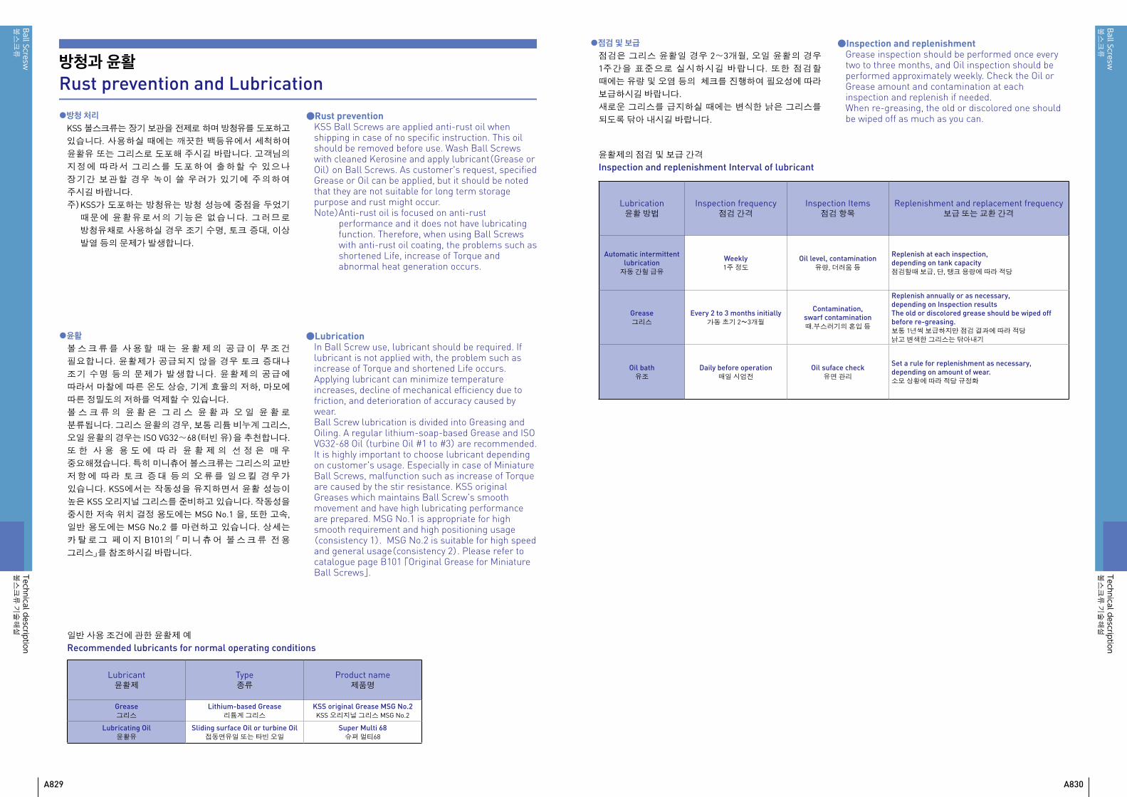
일반 사용 조건에 관한 윤활제 예Recommended lubricants for normal operating conditions
Lubricant윤활제
Type종류
Product name제품명
Grease그리스
Lithium-based Grease리튬계 그리스
KSS original Grease MSG No.2KSS 오리지널 그리스 MSG No.2
Lubricating Oil윤활유
Sliding surface Oil or turbine Oil접동면유일 또는 타빈 오일
Super Multi 68슈퍼 멀티68
●점검 및 보급점검은 그리스 윤활일 경우 2~3개월, 오일 윤활의 경우 1주간을 표준으로 실시하시길 바랍니다. 또한 점검할 때에는 유량 및 오염 등의 체크를 진행하여 필요성에 따라 보급하시길 바랍니다.새로운 그리스를 급지하실 때에는 변식한 낡은 그리스를 되도록 닦아 내시길 바랍니다.
윤활제의 점검 및 보급 간격Inspection and replenishment Interval of lubricant
●Inspection and replenishmentGrease inspection should be performed once every two to three months, and Oil inspection should be performed approximately weekly. Check the Oil or Grease amount and contamination at each inspection and replenish if needed.When re-greasing, the old or discolored one should be wiped off as much as you can.
Lubrication윤활 방법
Inspection frequency점검 간격
Inspection Items점검 항목
Replenishment and replacement frequency보급 또는 교환 간격
Automatic intermittent lubrication
자동 간헐 급유Weekly1주 정도
Oil level, contamination유량, 더러움 등
Replenish at each inspection, depending on tank capacity점검할때 보급, 단, 탱크 용량에 따라 적당
Grease그리스
Every 2 to 3 months initially가동 초기 2~3개월
Contamination, swarf contamination때.부스러기의 혼입 등
Replenish annually or as necessary, depending on Inspection resultsThe old or discolored grease should be wiped off before re-greasing.보통 1년씩 보급하지만 점검 결과에 따라 적당낡고 변색한 그리스는 닦아내기
Oil bath유조
Daily before operation매일 시업전
Oil suface check유면 관리
Set a rule for replenishment as necessary,depending on amount of wear.소모 상황에 따라 적당 규정화

A831 A832
ボー
ルね
じBall Scresw볼스크류
Ball Scresw볼스크류
기술해설
Technical description
ボー
ルね
じBall Scresw볼스크류
Ball Scresw볼스크류
기술해설
Technical description
그림 A-110 : 자바라와 테레스 코핏크 파이프Fig. A-110 : Bellows & Telescopic pipe
방진Dust prevention
볼스크류는 기능상 너트에 먼지나 이물이 혼입되어 마모가 빨리 진행하거나 또한 나사홈의 손상, 볼의 파손, 순환부의 파손 등에 따라서 작동 불가한 경우가 있습니다. 따라서 먼지나 이물의 혼입을 생각할 경우 나사가 외부에 노출하지 않도록 자바라나 Telescopic pipe 등의 방진 대책도 추천합니다.
KSS 볼스크류는 미니츄어 볼스크류의 특장을 살리기 위하여 콤팩트 설계에 중점을 두고 있습니다. 그러므로 카탈로그 게재 모델에 관해서는 씰을 장착하지 않는 치수로 되어 있 습 니 다. 씰 을 원 하 실 경 우 KSS에 문 의 하 여 주 시 길 바랍니다. 씰을 설치함에 따라서 너트 치수가 변경될 경우가 있으므로 양해바랍니다. 또한 모델에 따라서 씰의 설치가 되지 않을 경우도 있으므로 양해 부탁드립니다.
In Ball Screws, if dust or other contaminations intrude into the Ball Nut, wear is accelerated, the screw groove will be damaged, circulation will be obstructed due to Ball fracture, damage of recirculation parts and so on. Eventually, the Ball Screws will cease to function. Where the possibility of dust or other contaminant exists, the screw thread section cannot be left exposed, and dust prevention measure such as a bellows or Telescopic pipe must be taken.
KSS Ball Screws are concentrated on compact design for a feature of Miniature Ball Screw. Therefore, all models in the catalogue are the dimension without seals. Please inquire KSS if seals are required. Please note that Nut dimension may change due to seal installation. Some models cannot install the seals.
표면 처리Surface treatment
KSS에서는 방청을 목적으로서 볼스크류에 표면 처리를 실시할수 있습니다. KSS에서 방청을 목적으로 한 표면 처리는 블랙 크롬 처리를 표준으로 하고 있습니다. 기타의 표면 처리를 원하실 경우 KSS에 조회하여 주시길 바랍니다.
Surface treatment can be possible for the purpose of rust prevention. Black Chrome treatment(BCr) is KSS standard surface treatment for the purpose of rust prevention. Please inquire KSS if other surface treatments are needed.
●KSS 블랙 크롬 처리 볼스크류의 특징・ 얇은 막두께 (2~3μm)이므로 맞춤 부품의 대응이
가능합니다.・ 엄격한 공정 관리에 의하여 막두께를 균일하게 처리할수
있으므로 작동성을 손상시키는 일은 없습니다.・ 밀착성이 좋은 피막이므로 높은 방청 능력을 보유하고
있습니다.・ 미끄럼 특성을 향상시키실 경우 불소 플라스틱 코팅의
병용도 가능합니다.
●방청 능력 시험 데이터 Examination data of anti-rust ability염수 분무 시험(JIS Z2371)을 기준으로 표준 시험편을 사용하여 방청 능력을 평가한 결과를 아래에 표시합니다.
Based on the salt spray corrosion test(JIS Z2371), anti-rust ability has been evaluated, as follows.
・표준 시험편 / Standard test piece : 70mm×150mm×1mm(SPCC材 / material = SPCC )・데이터 / Data : 염수 분무 시험 24시간후의 외관과 등급 넘버법에 따른 평가 결과(수자가 작을수록 부식이 많음)
Evaluated by appearance and rating number method after 24 hours of salt spray corrosion test.(The less number, the more corrosion)
●RoHS대응에 관하여 About RoHS complianceKSS블랙 크롬 처리 볼스크류의 Cr+6 량은 RoHS로 규정되여있는 역치를 밑돌고 있기에 문제는 없습니다.
The Cr+6 amount of KSS Black Chrome(BCr) coating is less value than the based on RoHS regulation.
● Feature of KSS Ball Screws with Black Chrome(BCr) coating・ Due to thin film thickness(2~3μm), mating part
can be applicable with BCr.・ Due to strict production management,
film thickness can be treated equally and smoothness is kept.
・High anti-rust ability is possible. ・ To improve sliding characteristics, BCr+fluorine
resin coating is also available.
사진 A-111 : 블랙 크롬 처리품Photo A-111 : Black Chrome coating
Sample A시험편A
Sample B시험편B
Sample C시험편C
Rating number(Average)등급 넘버(평균치)
Sample A(BCr coating)시험편A(BCr처리) 9.3
Sample B(R coating)시험편B(R처리) 9~8
Sample C(M coating)시험편C(M처리) 3~4
Bellows Telescopic pipe

A833 A834
ボー
ルね
じBall Scresw볼스크류
Ball Scresw볼스크류
기술해설
Technical description
ボー
ルね
じBall Scresw볼스크류
Ball Scresw볼스크류
기술해설
Technical description
트레이서 빌리티Traceability
KSS 볼스크류는 엄선한 재료를 고도로 온도 관리가 된 공장에 우수한 기계 설비를 구사하여 각 제조 공정에서 검사, 출하까지 일관한 관리 체제에 따라서 생산되고 있습니다.출 하 검 사 에 합 격 한 볼 스 크 류 는 요 구 에 따 라 서 합격증(사진A-112)또는 검사 성적표(사진 A-113)를 첨부할 수 있습니다.KSS에서 생산된 볼스크류는 너트에 제조 번호가 마킹되어 있습니다.(사진 A-114).제조 번호에 대응된 출하 검사 이력이나 제조 이력은 사내에 보관되어 있으며 제조 번호에 따라 문의하여 출하 검사 데이터를 재현할 수 있습니다.
KSS Ball Screws are manufactured from rigidly selected materials in our temperature controlled factory. They are manufactured using the latest production equipment, with consistent quality control supervision ranging from the production process to inspection and shipping.Certificate of inspection, Photo A-112, or Inspection report, Photo A-113 can be provided as your request.The Ball Screws produced by KSS have a serial number which is marked on the Nut (refer to the Photo A-114). Record of inspection and production trail which is in correspondence to a production number, are stored in KSS and inspection data can be retrieved by inquiry of a serial number.
사진 A-114 : 제조 번호Photo A-114 : Serial Number
사진 A-113 : 검사 성적표Photo A-113 : Inspection report
볼스크류의 각 특성 계산예Calculation example of characteristic for Ball Screws.
볼스크류의 각 특성 계산예를 이하에 게재합니다. 모두 모델화 한 계산예로서 실제적으로 맞지 않는 경우도 있기에 이해해주시길 바랍니다.
볼스크류 제원샤프트 외경=φ10mm리드=10mm기본 동정격하중Ca=3,300N볼스크류 전체 길이=180mm축방향 유격=20μm以下
Ball Screw spec.Shaft dia.=φ10mmLead=10mmDynamic Capacity Ca=3,300NTotal length=180mmAxial play=20μm or less
회전 조건최고 속도=0.4m/sec
**리드10mm에 따라2,400 minー1
가감속 시간=0.05 sec**그림중①③⑤⑦
등속 시간=0.1 sec**그림중②⑥
정지 시간=0.2 sec**그림중④⑧
1사이클=0.8sec
Operating PatternMax Speed=0.4m/sec
** 2,400 minー1 because of Lead 10mmAcceleration & Deceleration time=0.05 sec
**①③⑤⑦ in diagram aboveConstant speed time=0.1 sec
**②⑥ in diagram aboveHalt time=0.2 sec
**④⑧ in diagram aboveCycle time=0.8sec
Calculation example of characteristic for Ball Screws are mentioned as follows. Each calculation example is modeled so that there is a case which is unrealistic.
예1 : 종축 사양 Pick&PlaceExample 1 : Vertical Pick&Place
볼스크류 모델 및 사용 조건Ball Screw model and operating condition
사진 A-112 : 합격증
m
Mass/=10kg
Up&Down
Motor/
①
Operating pattern(회전 사이클 선도)
②③
④
⑤
⑥
⑦
⑧
Speed(속도)
Time(시간)
Up(상승)
Down(하강)
1cycle(1사이클)=0.8sec
Photo A-112 : Certificate of Inspection

A835 A836
ボー
ルね
じBall Scresw볼스크류
Ball Scresw볼스크류
기술해설
Technical description
ボー
ルね
じBall Scresw볼스크류
Ball Scresw볼스크류
기술해설
Technical description
1)Calculation of Load conditionLoad condition of each operation pattern which is numbered is as follows.
①Down&Acceleration、⑦Up&Deceleration : F1=mgーmα②、⑥Constant Speed area : F2=mg③Down&Deceleration、⑤Up&Acceleration : F3=mg+mα
m : Mass=10 kg g : Gravity Acceleration=9.807 m/sec2
α : Acceleration Acceleration up to 0.4m/sec α=0.4/0.05=8 m/sec2
1)하중 조건의 산출번호화된 각 회전 패턴의 하중조건은 이하입니다.
①하강 가속 및 ⑦상승 감속 : F1=mgーmα②⑥등속 : F2=mg③하강 감속 및 ⑤상승 가속 : F3=mg+mα
여기서 m : 이동 물질량=10 kg g : 중력 가속도=9.807 m/sec2
α : 가속도 0.4m/sec 에 도달할때까지의 가속도 α=0.4/0.05=8 m/sec2
2)Calculation of Speed conditionRevolution of each operation pattern which is numbered is as follows.
Constant speed area(②、⑥) : 0.4 m/sec =0.4×60 m/min=24 m/min
=2,400 minー1(Lead 10mm)Acceleration and deceleration area(①、③、⑤、⑦) : as above average revolution, 2,400/2=1,200 minー1
2)속도 조건의 산출번호화된 회전 패턴의 회전수는 이하입니다.
등속일때(②⑥) : 0.4 m/sec =0.4×60 m/min=24 m/min
=2,400 minー1(리드10mm에 의하여)가감속할때(①③⑤⑦) : 상기의 평균 회전수로서, 2,400/2= 1,200 minー1
3)평균하중, 평균 회전수 산출
상기의 계산 결과를 정리하여 카탈로그 p-A825에 표시한 평균 하중 Fam과 평균 회전수 Nm을 계산합니다.
3)Calculation of average Load, average RevolutionCalculation based on the above, calculate the average Load Fam shown in catalogue p-A825 and the average Revolution Nm .
Fam = (
Nm =
)⅓ N
minー1
N1・t1+N2・t2+N3・t3
Fa13・N1・t1+Fa2
3・N2・t2+Fa33・N3・t3
t1+t2+t3
N1・t1+N2・t2+N3・t3
Operating Pattern조 건
Axial load축방향 하중
N
Revolution회전수minー1
time사용 시간
sec
①、⑦ Fa1=18.1 N1=1,200 t1=0.05×2=0.1
②、⑥ Fa2=98.1 N2=2,400 t2=0.1×2=0.2
③、⑤ Fa3=178.1 N3=1,200 t3=0.05×2=0.1
Average평 균 Fam=116.3 Nm=1,800
Total(합계)0.4sec1 cycle(1사이클) : t=0.8 secHalt time(휴지) : 0.4 sec(50%)
기본 정격 수명 / Basic Rating Life L10h ={106/(60・Nm)} × {Ca/(f・Fam)}3 시간 / hours
L10h = 96,280 시간 / hours
f : 하정 계수 / Load coefficient (1.3로 가정 / Assumption 1.3 )Ca : 기본 동정격하중 / Basic Dynamic Load Rating (3,300 N)
4)Calculation of Basic Rating LifeUsing average Load and average Revolution, Basic Rating Life is calculated according to the catalogue page A825.
4)기본 정격 수명의 산출평균 하중. 평균 회전수의 값을 사용하여 기본 정격 수명을 카탈로그 페이지 A825에 준수하여 계산합니다.
Due to halt time is 50%,96,280/0.5 = 192,560 hours operation. If 24 hours operation is premised.192,560/24 = 8,023 days, it shows that enough life is kept.
휴지 시간은 50%이기때문에 가동시간은 96,280/0.5 = 192,560입니다.24시 간 가 동 을 전 제 로 할 경 우 192,560/24 = 8,023일로서 충분한 수명을 확보할수 있습니다.
기본 정격 수명의 계산Calculation of Basic Rating Life
기본 정격 수명은 이하의 순서로 산출됩니다.Basic Rating Life is calculated in the following procedure.
각 회전패턴에서 하중 조건을 산출Calculation of Load condition for each operating pattern
각 회전패턴에서 속도 조건을 산출Calculation of Speed condition for each operating pattern
평균 하중평균 회전수의 산출Calculation of average Load and Revolution
정격 수명의 계산Calculation of Basic Rating Life

A837 A838
ボー
ルね
じBall Scresw볼스크류
Ball Scresw볼스크류
기술해설
Technical description
ボー
ルね
じBall Scresw볼스크류
Ball Scresw볼스크류
기술해설
Technical description
1)가속 토크 T1 의 산출(Calculation of acceleration Torque T1 )
T1 = α ・I = α (Iw+Is) N・mα : 각 가속도(Angular acceleration) rad/sec2
I : 관성 모멘트(Inertia moment) kg・m2
Iw : 이동물의 모터축 환산의 관성 모멘트 kg・m2
(Inertia moment of moving object by motor axial conversion)Is : 나사축의 관성 모멘트(Inertia moment of Screw Shaft) kg・m2
Iw = mW ×(ℓ/2π)2 = 2.53 × 10ー5 kg・m2
mW : 이동 물질량(Mass of moving object)= 10 kgℓ : 볼스크류 리드(Ball Screw Lead)= 0.01 m
Is = mS×(d2/8)=(d/2)2πγ × L ×(d2/8)= 0.139 × 10ー5 kg・m2
mS : 나사축 질량(Mass of Screw Shaft) kgγ : 나사축 비중(Specific gravity of Screw Shaft)= 7,850 kg/m3
d : 나사축 외경(Shaft dia.)= 0.01 m L : 나사축 길이(Shaft length)= 0.18 m
α = (2πN)/60t = 5,026.5 rad/sec2
N : 최고 속도(Max speed)= 2,400 minー1
t : 가속 시간(Acceleration time)= 0.05sec
T1 = 5,026.5 ×(2.53 + 0.139)× 10ー5 = 0.134 N・m
2)부하 토크T2의 산출(Calculation of Load Torque T2)
T2=mgℓ/(2πη)= 0.173 N・mm : 이동 물질량(Mass of moving object)= 10 kg g : 중력 가속도(Gravity acceleration)= 9.807 m/sec2
ℓ : 볼스크류 리드(Ball Screw Lead)= 0.01 mη : 볼스크류 효율(Ball Screw efficiency)= 0.9
T = T1 + T2 = 0.134 N・m + 0.173 N・m = 0.307 N・m
3) Calculation of Driving Torque T for feed screw systemIn case without consideration of Torque by support Bearings, Driving Torque of Ball Screw is as follows.
3)이송 나사계의 구동 토크T의 산출상기의 계산에 지지베어링 등에 따른 토크를 고려하지 않을 경우 볼스크류 축계의 구동토크는 이하입니다.
예2 : 횡축 사양 소형 선반Example 2 : Horizontal Small lathe볼스크류 모델 및 사용 조건Ball Screw model and operating condition
이송 나사계의 구동 토크 계산카탈로그 페이지 A827에 준수하여 이송 나사계의 구동 토크를 계산합니다. 이것은 모터를 선정할때 중요합니다.상기 사례의 경우, 예압 사양의 볼스크류가 아니기 때문에 예압 다이나믹 토크는 발생하지 않습니다. 그러므로 가속 토크T1, 부하 토크T2에 관해서 계산합니다.
Calculation of Driving Torque for feed screw systemCalculate Driving Torque for feed screw system according to the catalogue page A827. It is important when motor selection. In the above case, due to backlash type Ball Screw, Preload Dynamic Drag Torque does not occur. Therefore, calculate acceleration Torque T1 and Load Torque T2.
T = T1 + T2 + T3 + T4 N・m
T1 : 가속에 따른 토크(Acceleration Torque) N・mT2 : 부하 토크(Load Torque) N・mT3 : 예압 다이나믹 토크(Preload Dynamic Drag Torque) N・mT4 : 기타 토크(Additional Torque) N・m
볼스크류 제원샤프트 외경=φ12mm리드=2mm샤프트 곡경 d=φ10.6mm기본 동정격하중Ca=1,900N설치 사이거리 L=400mm축방향 유격=0μm以下이동 물질량 m=500kg접동면 마찰계수 μ=0.01
Ball Screw spec.Shaft dia.=φ12mmLead=2mmShaft Root dia. d=φ10.6mmDynamic Capacity Ca=1,900NMounting span L=400mmAxial play=0μm or lessMass of moving object m=500kgSliding surface friction coefficient μ=0.01
회전 조건최고 속도=5m/min
**리드2mm에 따라2,500 minー1
사이클 도표: 위의 그림 참조 ①가속=0.25sec ②등속=0.5sec ③감속=0.25sec ④부하 작용시=4.0sec
부하 하중= 200N절삭시 이송=50 minー1
Operating PatternMax Speed=5m/min
** 2,500 minー1 because of Lead 2mmOperating pattern : see diagram above
①Acceleration=0.25sec ②Constant speed=0.5sec ③Deceleration=0.25sec ④Working=4.0sec
Load= 200NRevolution at turning=50 minー1
SupportedFixed Fixed
L : Critical speed(Fixed-Supported)
L : Buckling load(Fixed-Fixed)
Motor/
0.5sec
①
Operating pattern( )
②③
④
Speed( )
Time( )
0.25sec 0.25sec
Load( )=200NSpeed( )=50min-1
4.0sec
Max speed( )=2,500min-1

A839 A840
ボー
ルね
じBall Scresw볼스크류
Ball Scresw볼스크류
기술해설
Technical description
ボー
ルね
じBall Scresw볼스크류
Ball Scresw볼스크류
기술해설
Technical description
2)Study of permissible Load for yield stressCalculate permissible Load for yield stress based on catalogue page A815.
2)항복 응력에 대한 허용 하중의 검토카 탈 로 그 페 이 지 A815의 계 산 식 에 기 존 하 여 계산합니다.
Substitute permissible stress σ=98N/mm2(MPa), Root diameter d=10.6mm in the formula above.
It is more than maximum Load and there is no problem.
따라서 사용 하중보다 충분히 크기에 문제는 없습니다.
P = 8,650 N P = 8,650 N
상기 계산식에, 허용 응력 σ=98N/mm2(MPa)곡경 d=10.6mm를 대입합니다.
P = σ × A N A = d2 mm2
4π
Calculation of permissible Axial load1)Study of Buckling load
Calculate Buckling load according to the following formula in Catalogue page A815.
허용 축방향 하중의 계산1)좌굴 하중의 검토
카 탈 로 그 페 이 지 A815의 계 산 식 에 기 존 하 여 좌 굴 하중을 계산합니다.
P = α × I = d4 mm4 NL2
nπ2E・I64π
상기 계산식에, 안전율 α=0.5탄성률 E=2.08×10⁵N/mm2(MPa)곡경 d=10.6mm고정-고정의 설치 계수 n=4설치 사이거리 L=400mm를 대입합니다.
P = 15,900N
따라서 사용 하중보다 충분히 크기에 문제는 없습니다.
Substitute safety factor α=0.5,Young's modulus E=2.08×10⁵N/mm2(MPa)Root diameter d=10.6mm,Fixed-Fixed mounting factor n=4,mounting span distance L=400mm in formula above.
P = 15,900N
It is more than maximum Load so that there is no problem.
허용 회전수의 계산카 탈 로 그 페 이 지 A816의 계 산 식 에 기 존 하 여 계산합니다.
Calculation of permissible RevolutionCalculate permissible Revolution based on the catalogue page A816
상기 계산식에, 안전률 β=0.8탄성률 E=2.08×10⁵N/mm2(MPa)중력 가속도 g= 9.8×103 mm/sec2 비중 γ=7.7×10⁻⁵N/mm3
곡경 d=10.6mm고정-지지의 설치 계수 λ=3,927설치 사이 거리 L=400mm을 대입합니다.
N = 10,000 minー1
따라서 최고 회전수보다 충분히 크게 문제 없습니다.
Substitute safety factor β=0.8, Young's modulus E=2.08×10⁵N/mm2(MPa),gravity acceleration g= 9.8×103 mm/sec2,material specific gravity γ=7.7×10⁻⁵N/mm3,Root diameter d=10.6mm, Fixed-Support mounting factor λ=3.927, mounting span distance L=400mm in formula above.
N = 10,000 minー1
Therefore, it is more than maximum Revolution and there is no problem.
N =β × minー1 {rpm}× 2π60・λ2
γ ・A ・L4
E ・I ・g
I = d4 mm4
64π
A = d2 mm2
4π

A841 A842
ボー
ルね
じBall Scresw볼스크류
Ball Scresw볼스크류
기술해설
Technical description
속도(Speed)V=5m/min = 83.3mm/sec가속도(Acceleration) α = 83.3/0.25 = 333 mm/sec2 = 0.333 m/sec2
가감속에 따른 하중(Load due to Acceleration) F = mα = 500×0.333 = 167 N이동물에 따른 하중(Load of moving object) = 등속때의 하중(Load during constant speed) F1 = μmg = 49N등속때의 회전수(Revolution at constant speed) N1 = 2,500 minー1
가감속때의 하중(Load during acceleration) F2 = F + F1 = 216N가감속때의 회전수(Revolution at acceleration) N2 = 2,500 /2 = 1,250 minー1
절삭때의 하중(Load during turning) F4 = 200N + F1 = 249N절삭때의 회전수(Revolution at turning) N4 = 50 min-1
이상의 결과를 정리한 것이 이하의 표입니다.Sum up calculation results above, results are as follows.
기본 정격 수명의 계산 Calculation of Basic Rating Life1) 사이클 도표로부터 하중 조건의 산출
Calculation of Load condition according to the operating pattern diagram
Operating Pattern조 건
Axial load(F)하중(F)
N
Revolution(N)회전수(N)
minー1
time(t)사용 시간(t)
sec
Percentage사용 빈도
%
① 가속 216 1,250 0.25 5
② 등속 49 2,500 0.5 10
③ 감속 216 1,250 0.25 5
④ 절삭 249 50 4.0 80
2) 평균 하중, 평균 회전수의 산출 카탈로그 페이지 A825에 따라 평균하중을 계산합니다.
2) Calculation of average Load, average RevolutionAccording to catalogue page A825, average Load Fam is as follows.
위의 표의 수치를 대입하면, Fam = 166N
또한 평균회전수에 관해서도 카탈로그 페이지 A825의 형식에 위의 표의 수치를 대입하여, Nm = 415 minー1로 됩니다.
Substitute each number in table in the formula above, Fam = 166N
In case of the average Revolution, substitute each number in table in the following formula,Nm = 415 minー1
Fam = ( )⅓ NN1t1+N2t2+N3t3+N4t4
F13N1t1+F2
3N2t2+F33N3t3+F4
3N4t4
Nm = ( ) = 415minー1
t1+t2+t3+t4
N1t1+N2t2+N3t3+N4t4
3) 기본 정격 수명의 계산 평균 하중 Fam 과 평균 회전수 Nm을 카탈로그 페이지 A825의 수명 계산식에 대입하면 하기와 같습니다.
3) Calculation of Basic Rating LifeSubstitute the average Load Fam and Revolution Nm in the following formula, page A825 in catalogue.
여기서 기본 동정격하중 Ca = 1900N하중 계수 f = 1.2입니다.
Here, Basic Dynamic Load Rating Ca = 1900N, Load factor f = 1.2.
( )3= 3.48 × 10⁴ 시간(hours)f・FamCa
L10h = ( )×60・Nm
106