Embed Size (px)
Citation preview
7/27/2019 EE3601 lab2.v2
http://slidepdf.com/reader/full/ee3601-lab2v2 1/4
EE 3601
Lab 2 - Transformer Characteristics
0. Prelab (to be completed INDIVIDUALLY)
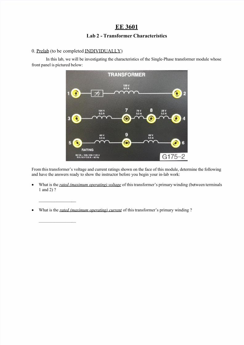
In this lab, we will be investigating the characteristics of the Single-Phase transformer module whosefront panel is pictured below:
From this transformer’s voltage and current ratings shown on the face of this module, determine the following
and have the answers ready to show the instructor before you begin your in-lab work:
What is the rated (maximum operating) voltage of this transformer’s primary winding (between terminals
1 and 2) ?
_________________
What is the rated (maximum operating) current of this transformer’s primary winding ?
_________________
7/27/2019 EE3601 lab2.v2
http://slidepdf.com/reader/full/ee3601-lab2v2 2/4
1. Turns Ratio Investigation
Determine the relationships between the three windings of the Single-Phase transformer module by performing the following experimental steps:
Make sure that the switches of the main Power Supply are set to the 0 (OFF) position, and the voltagecontrol knob is turned fully ccw to 0. Then set the voltmeter select switch to the 4-N position.
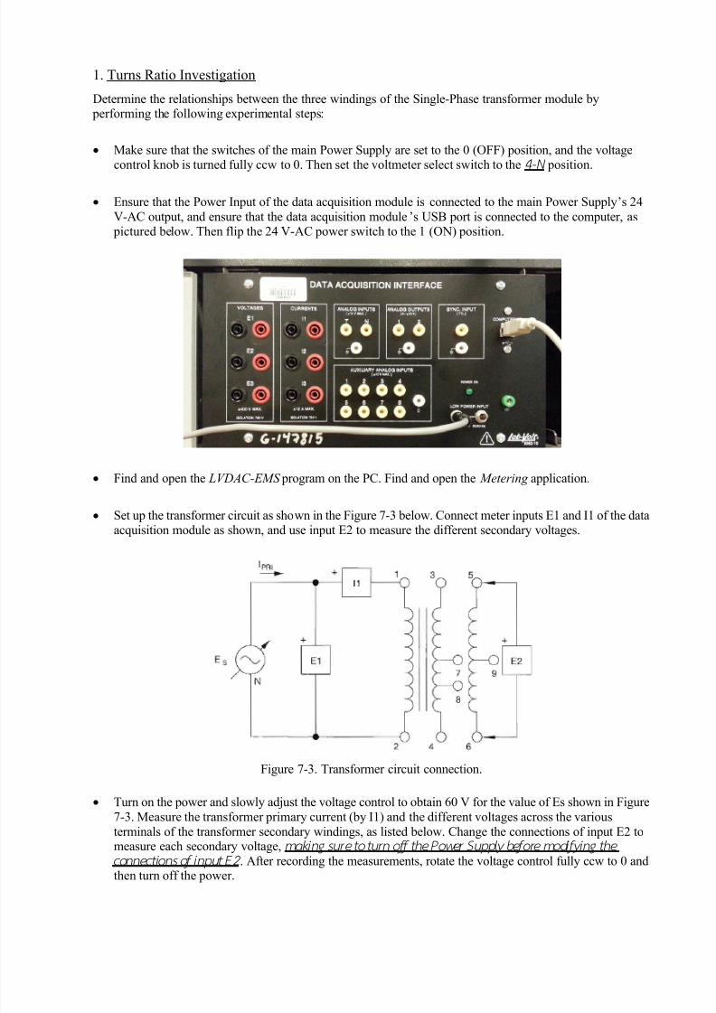
Ensure that the Power Input of the data acquisition module is connected to the main Power Supply’s 24
V-AC output, and ensure that the data acquisition module’s USB port is connected to the computer, as pictured below. Then flip the 24 V-AC power switch to the 1 (ON) position.
Find and open the LVDAC-EMS program on the PC. Find and open the Metering application.
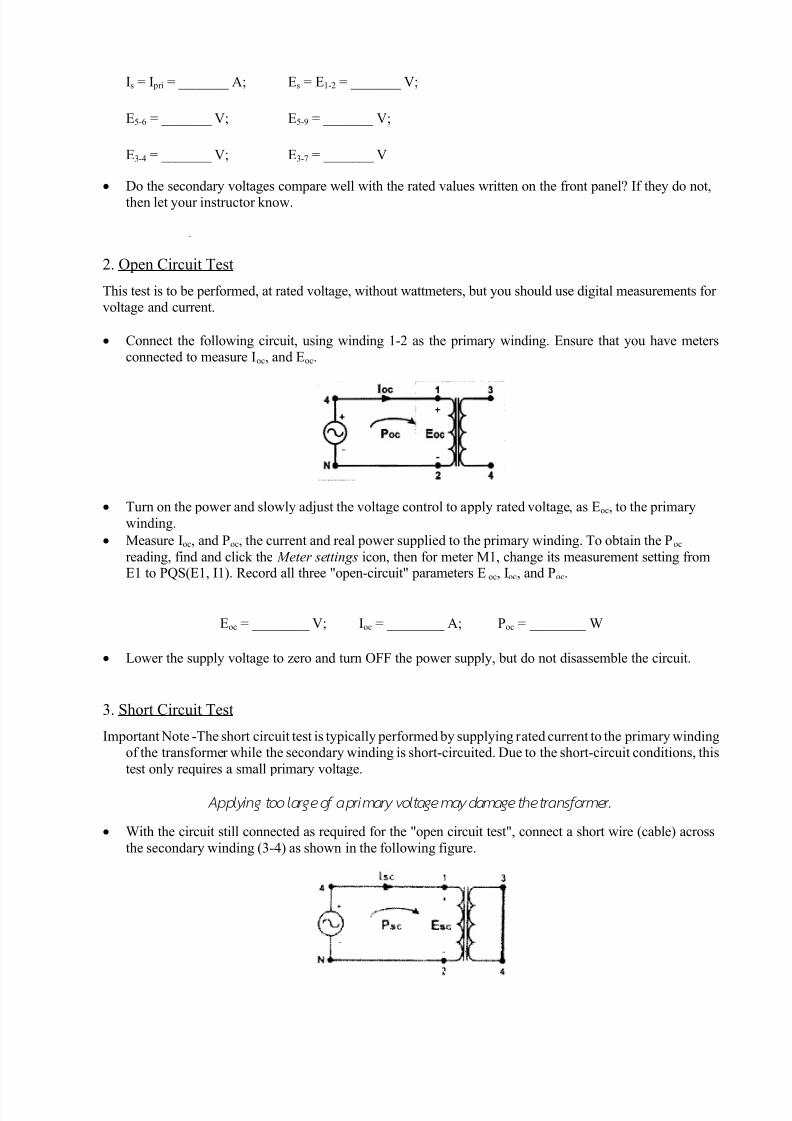
Set up the transformer circuit as shown in the Figure 7-3 below. Connect meter inputs E1 and I1 of the data
acquisition module as shown, and use input E2 to measure the different secondary voltages.
Figure 7-3. Transformer circuit connection.
Turn on the power and slowly adjust the voltage control to obtain 60 V for the value of Es shown in Figure
7-3. Measure the transformer primary current (by I1) and the different voltages across the various
terminals of the transformer secondary windings, as listed below. Change the connections of input E2 tomeasure each secondary voltage, making sure to turn of f the Power Supply before modif ying the
connections of input E2 . After recording the measurements, rotate the voltage control fully ccw to 0 andthen turn off the power.
7/27/2019 EE3601 lab2.v2
http://slidepdf.com/reader/full/ee3601-lab2v2 3/4
Is = I pri = _______ A; Es = E1-2 = _______ V;
E5-6 = _______ V; E5-9 = _______ V;
E3-4 = _______ V; E3-7 = _______ V
Do the secondary voltages compare well with the rated values written on the front panel? If they do not,then let your instructor know.
~
2. Open Circuit Test
This test is to be performed, at rated voltage, without wattmeters, but you should use digital measurements for voltage and current.
Connect the following circuit, using winding 1-2 as the primary winding. Ensure that you have metersconnected to measure Ioc, and Eoc.
Turn on the power and slowly adjust the voltage control to a pply rated voltage, as Eoc, to the primary
winding.
Measure Ioc, and Poc, the current and real power supplied to the primary winding. To obtain the Poc
reading, find and click the Meter settings icon, then for meter M1, change its measurement setting fromE1 to PQS(E1, I1). Record all three "open-circuit" parameters E oc, Ioc, and Poc.
Eoc = ________ V; Ioc = ________ A; Poc = ________ W
Lower the supply voltage to zero and turn OFF the power supply, but do not disassemble the circuit.
3. Short Circuit Test
Important Note -The short circuit test is typically performed by supplying rated current to the primary windingof the transformer while the secondary winding is short-circuited. Due to the short-circuit conditions, this
test only requires a small primary voltage.
Applying too large of a primary voltage may damage the transformer.
With the circuit still connected as required for the "open circuit test", connect a short wire (cable) across
the secondary winding (3-4) as shown in the following figure.
7/27/2019 EE3601 lab2.v2
http://slidepdf.com/reader/full/ee3601-lab2v2 4/4
Check to be sure that the supply voltage is set to zero , and then turn ON the supply. Carefully
increase the voltage (should not exceed 10 V) until rated current, as Isc, is applied to the primary
winding.
Measure Esc, and Psc, the voltage and real power supplied to the primary winding. Record all three
"short-circuit" parameters Esc, Isc, and Psc.
Esc = ________ V; Isc = ________ A; Psc = ________ W
Lower the supply voltage to zero and then turn OFF the supply
Remove all cables connected to the transformer, and put away all wires and equipment.
4. Lab Report (to be submitted as a typed document via D2L)
The lab report should start with a brief summary about what was to be done in the experiment. The
remaining part of the report should consist of the information asked below, and it should conclude with any
discussion you feel is necessary, e.g., note what worked well in this exercise and what did not work well,
and/or add any suggestions for the improvement of this exercise.
Prelab Results
Include the rated voltage and current values of this transformer’s primary winding.
Turns Ratio Investigation
Include all measured voltage and current values obtained during this investigation.
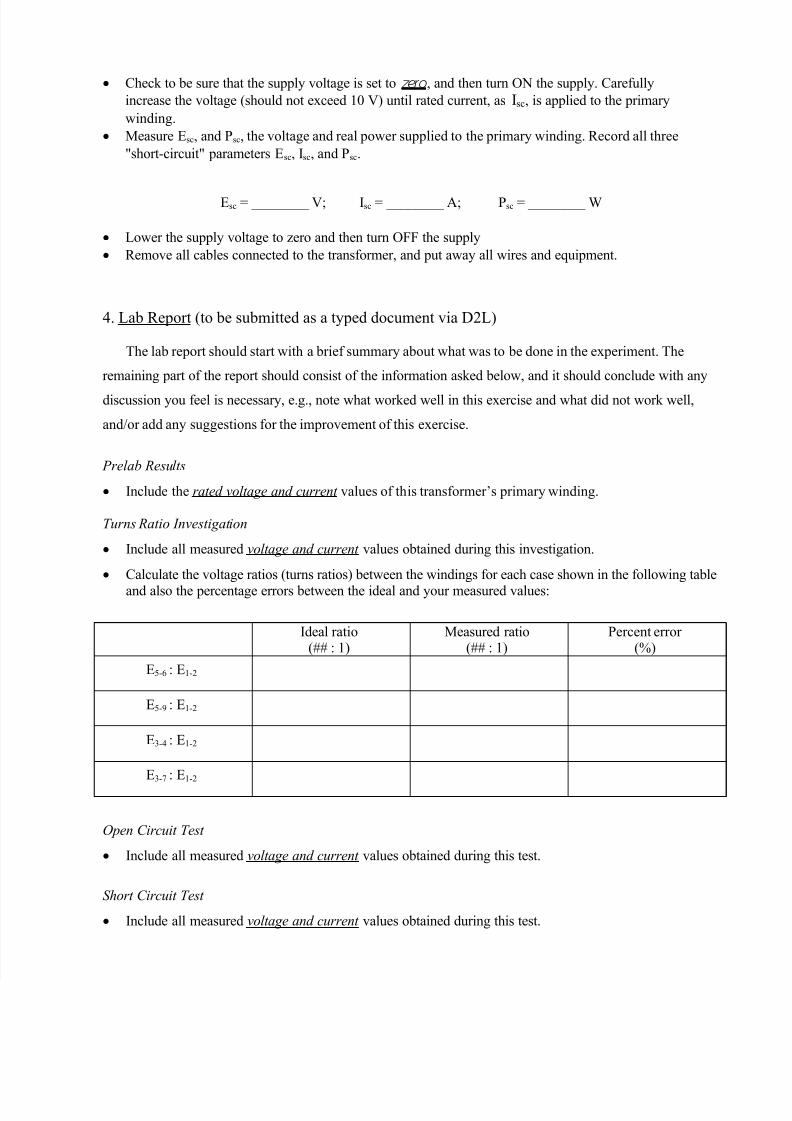
Calculate the voltage ratios (turns ratios) between the windings for each case shown in the following table
and also the percentage errors between the ideal and your measured values:
Ideal ratio(## : 1)
Measured ratio(## : 1)
Percent error (%)
E5-6 : E1-2
E5-9 : E1-2
E3-4 : E1-2
E3-7 : E1-2
Open Circuit Test
Include all measured voltage and current values obtained during this test.
Short Circuit Test
Include all measured voltage and current values obtained during this test.