Embed Size (px)
Citation preview
ENTWICKLUNG Kettentrieb
382 MTZ 5/2004 Jahrgang 65
Eine neue Steuerketteohne Polygoneffekt
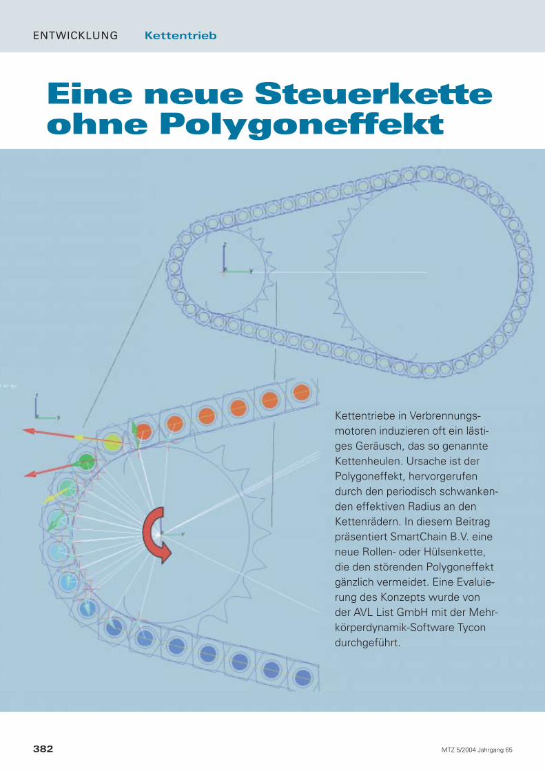
Kettentriebe in Verbrennungs-motoren induzieren oft ein lästi-ges Geräusch, das so genannteKettenheulen. Ursache ist derPolygoneffekt, hervorgerufendurch den periodisch schwanken-den effektiven Radius an denKettenrädern. In diesem Beitragpräsentiert SmartChain B.V. eineneue Rollen- oder Hülsenkette,die den störenden Polygoneffekt gänzlich vermeidet. Eine Evaluie-rung des Konzepts wurde von der AVL List GmbH mit der Mehr-körperdynamik-Software Tycondurchgeführt.
1 Einführung
Der Polygoneffekt ist einer der Hauptursa-chen für den vergleichsweise hohen Ge-räusch- und Schwingungspegel von Rollen-und Hülsenketten. Neben der Anregungvon longitudinalen und transversalenSchwingungen der Kettentrume ergebensich auch Einlaufstöße der Kettenglieder indie Kettenradverzahnung. Die durch denPolygoneffekt induzierte Geräuschanre-gung tritt üblicherweise dominant mit derEingriffsfrequenz des Kettentriebs (= Poly-gonfrequenz) auf. Fällt diese mit einer Ei-genfrequenz der Motorstruktur zusammen,tritt Resonanz auf, welche zu einer Überhö-hung des Körperschallpegels führt. Dasletztendlich abgestrahlte Geräusch ist be-kannt als Kettenheulen. Im Gegensatz zuRollen- und Hülsenketten haben Zahnket-ten (Silent Chain), aufgrund ihrer besonde-ren Kontaktkinematik günstigere akusti-sche Eigenschaften. Im Vergleich zur Hül-senkette ist deren Preis aber mindestensum den Faktor 2 höher. Außerdem ist derEinsatz von Zahnketten in hochbelastetenSteuertrieben, zum Beispiel bei Dieselmoto-ren mit Direkteinspritzung, kaum üblich.
Zahnriemen weisen im Allgemeinen einsehr gutes akustisches Verhalten auf, dieLebensdauer ist aber gerade bei Dieselap-plikationen oft inakzeptabel kurz.
2 Eine neue Kette ohnePolygoneffekt
Die neue Kette von SmartChain B.V. [5] isteine dauerhafte, kostengünstige Rollen-oder Hülsenkette, die keinen Polygoneffektaufweist. Es treten keine Einlaufstöße zwi-schen Kette und Kettenrad mehr auf, unddie Übersetzung ist völlig konstant. In the-oretischer Hinsicht ist zu erwarten, dass derGeräusch- und Schwingungspegel der neu-en Kette mindestens ebenso günstig ist wiejener der Zahnkette. Die neuen Ideen vonSmartChain B.V. sind mittels internationa-ler Patentanmeldungen geschützt.
Die neue Kette kann zum Beispiel im(Steuer)kettenantrieb von Nockenwellen,Einspritzpumpe, Massenausgleichsgetriebeoder Ölpumpe eines Verbrennungsmotorseingesetzt werden.
3 Theorie
Die Theorie hinter dem „Null-Polygonef-fekt“ dieser neuen, innovativen Kette istüberraschend einfach. Sie basiert auf ele-mentaren kinematischen Überlegungenund kann daher als schlüssig betrachtetwerden.
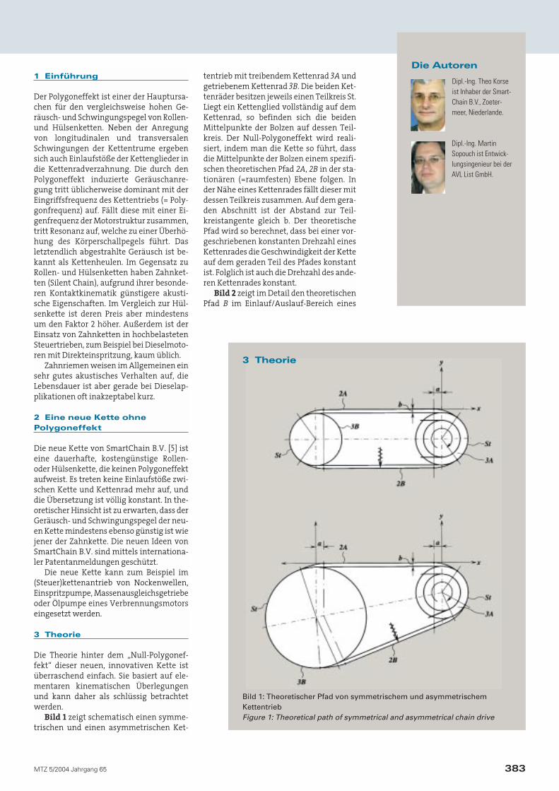
Bild 1 zeigt schematisch einen symme-trischen und einen asymmetrischen Ket-
tentrieb mit treibendem Kettenrad 3A undgetriebenem Kettenrad 3B. Die beiden Ket-tenräder besitzen jeweils einen Teilkreis St.Liegt ein Kettenglied vollständig auf demKettenrad, so befinden sich die beidenMittelpunkte der Bolzen auf dessen Teil-kreis. Der Null-Polygoneffekt wird reali-siert, indem man die Kette so führt, dassdie Mittelpunkte der Bolzen einem spezifi-schen theoretischen Pfad 2A, 2B in der sta-tionären (=raumfesten) Ebene folgen. Inder Nähe eines Kettenrades fällt dieser mitdessen Teilkreis zusammen. Auf dem gera-den Abschnitt ist der Abstand zur Teil-kreistangente gleich b. Der theoretischePfad wird so berechnet, dass bei einer vor-geschriebenen konstanten Drehzahl einesKettenrades die Geschwindigkeit der Ketteauf dem geraden Teil des Pfades konstantist. Folglich ist auch die Drehzahl des ande-ren Kettenrades konstant.
Bild 2 zeigt im Detail den theoretischenPfad B im Einlauf/Auslauf-Bereich eines
383MTZ 5/2004 Jahrgang 65
Die Autoren
Dipl.-Ing. MartinSopouch ist Entwick-lungsingenieur bei derAVL List GmbH.
Dipl.-Ing. Theo Korseist Inhaber der Smart-Chain B.V., Zoeter-meer, Niederlande.
Bild 1: Theoretischer Pfad von symmetrischem und asymmetrischem KettentriebFigure 1: Theoretical path of symmetrical and asymmetrical chain drive
3 Theorie
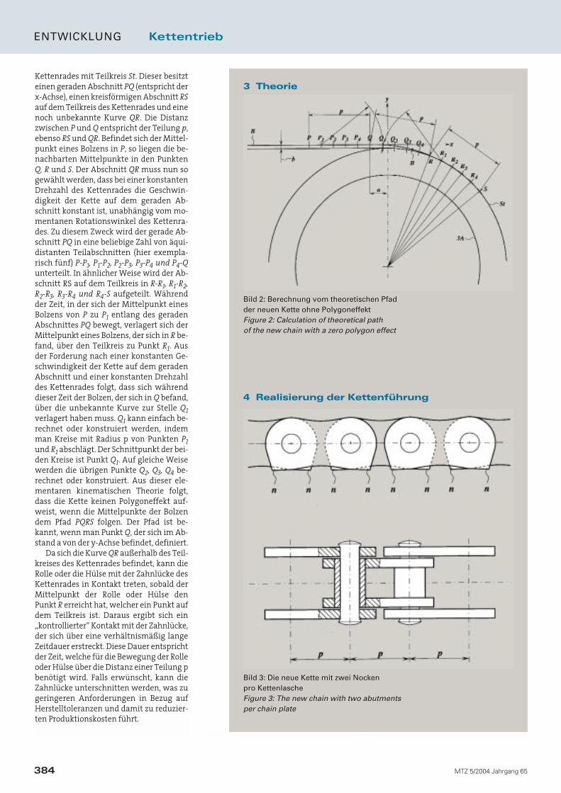
Kettenrades mit Teilkreis St. Dieser besitzteinen geraden Abschnitt PQ (entspricht derx-Achse), einen kreisförmigen Abschnitt RSauf dem Teilkreis des Kettenrades und einenoch unbekannte Kurve QR. Die Distanzzwischen P und Q entspricht der Teilung p,ebenso RS und QR. Befindet sich der Mittel-punkt eines Bolzens in P, so liegen die be-nachbarten Mittelpunkte in den PunktenQ, R und S. Der Abschnitt QR muss nun sogewählt werden, dass bei einer konstantenDrehzahl des Kettenrades die Geschwin-digkeit der Kette auf dem geraden Ab-schnitt konstant ist, unabhängig vom mo-mentanen Rotationswinkel des Kettenra-des. Zu diesem Zweck wird der gerade Ab-schnitt PQ in eine beliebige Zahl von äqui-distanten Teilabschnitten (hier exempla-risch fünf) P-P1, P1-P2, P2-P3, P3-P4 und P4-Qunterteilt. In ähnlicher Weise wird der Ab-schnitt RS auf dem Teilkreis in R-R1, R1-R2,R2-R3, R3-R4 und R4-S aufgeteilt. Währendder Zeit, in der sich der Mittelpunkt einesBolzens von P zu P1 entlang des geradenAbschnittes PQ bewegt, verlagert sich derMittelpunkt eines Bolzens, der sich in R be-fand, über den Teilkreis zu Punkt R1. Ausder Forderung nach einer konstanten Ge-schwindigkeit der Kette auf dem geradenAbschnitt und einer konstanten Drehzahldes Kettenrades folgt, dass sich währenddieser Zeit der Bolzen, der sich in Q befand,über die unbekannte Kurve zur Stelle Q1verlagert haben muss. Q1 kann einfach be-rechnet oder konstruiert werden, indemman Kreise mit Radius p von Punkten P1und R1 abschlägt. Der Schnittpunkt der bei-den Kreise ist Punkt Q1. Auf gleiche Weisewerden die übrigen Punkte Q2, Q3, Q4 be-rechnet oder konstruiert. Aus dieser ele-mentaren kinematischen Theorie folgt,dass die Kette keinen Polygoneffekt auf-weist, wenn die Mittelpunkte der Bolzendem Pfad PQRS folgen. Der Pfad ist be-kannt, wenn man Punkt Q, der sich im Ab-stand a von der y-Achse befindet, definiert.
Da sich die Kurve QR außerhalb des Teil-kreises des Kettenrades befindet, kann dieRolle oder die Hülse mit der Zahnlücke desKettenrades in Kontakt treten, sobald derMittelpunkt der Rolle oder Hülse denPunkt R erreicht hat, welcher ein Punkt aufdem Teilkreis ist. Daraus ergibt sich ein„kontrollierter“ Kontakt mit der Zahnlücke,der sich über eine verhältnismäßig langeZeitdauer erstreckt. Diese Dauer entsprichtder Zeit, welche für die Bewegung der Rolleoder Hülse über die Distanz einer Teilung pbenötigt wird. Falls erwünscht, kann dieZahnlücke unterschnitten werden, was zugeringeren Anforderungen in Bezug aufHerstelltoleranzen und damit zu reduzier-ten Produktionskosten führt.
ENTWICKLUNG Kettentrieb
384 MTZ 5/2004 Jahrgang 65
3 Theorie
Bild 2: Berechnung vom theoretischen Pfad der neuen Kette ohne Polygoneffekt Figure 2: Calculation of theoretical path of the new chain with a zero polygon effect
4 Realisierung der Kettenführung
Bild 3: Die neue Kette mit zwei Nocken pro KettenlascheFigure 3: The new chain with two abutments per chain plate
4 Realisierung der Kettenführung
Im einfachsten Fall lässt sich die Kettedurch eine stationäre (=raumfeste) Füh-rungsschiene auf den theoretischen Pfadzwingen. Nachteil dieses Führungssys-tems ist, dass die Kontaktkräfte und auchdie örtlichen Hertz‘schen Kontaktpressun-gen zwischen Kettenglied und Führungs-schiene, bedingt durch die kleinen Krüm-mungsradien in der Nähe des Kettenrades,groß sind. Außerdem entspricht dieSchlupfgeschwindigkeit zwischen Ketten-glied und stationärer Führungsschiene dervollen Kettengeschwindigkeit. Die Verlust-leistung ist hoch, ebenso wie der Ver-schleiß in den Kontaktzonen.
Wesentlich günstigere Bedingungen er-geben sich, wenn man die Kette sowohl inder rotierenden (=radfesten), als auch inder stationären Ebene führt. Dies wirddurch eine Modifikation der Geometrie derKettenlaschen realisiert, Bild 3.
Die ursprünglich annähernd „8-förmi-gen“ Laschen werden dabei auf einer Seitemit zwei präzise hergestellten Nocken nversehen. Auf jeder Seite des Kettenradeswird ein Ring montiert, der als eine rotie-rende Führung für die Nocken dient. DieKonturen der Nocken sind so berechnet,dass die Mittelpunkte der Bolzen der KurvePQRS folgen. Dabei wirkt die Kettenlaschemit dem Nocken in Verbindung mit demrotierenden Führungsring als Hebel. Durchdie stationären Führungsschienen werdendie Mittelpunkte der Bolzen entlang demgeraden Abschnitt PQ geführt.
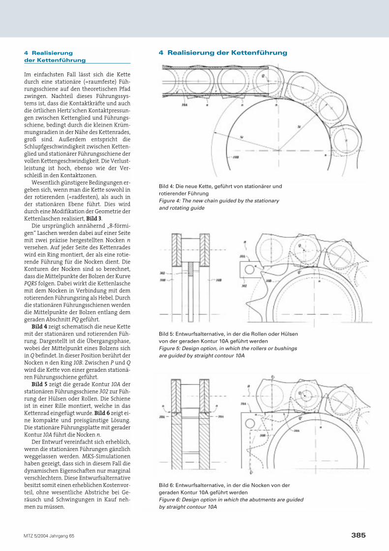
Bild 4 zeigt schematisch die neue Kettemit der stationären und rotierenden Füh-rung. Dargestellt ist die Übergangsphase,wobei der Mittelpunkt eines Bolzens sichin Q befindet. In dieser Position berührt derNocken n den Ring 10B. Zwischen P und Qwird die Kette von einer geraden stationä-ren Führungsschiene geführt.
Bild 5 zeigt die gerade Kontur 10A derstationären Führungsschiene 302 zur Füh-rung der Hülsen oder Rollen. Die Schieneist in einer Rille montiert, welche in dasKettenrad eingefügt wurde. Bild 6 zeigt ei-ne kompakte und preisgünstige Lösung.Die stationäre Führungsplatte mit geraderKontur 10A führt die Nocken n.
Der Entwurf vereinfacht sich erheblich,wenn die stationären Führungen gänzlichweggelassen werden. MKS-Simulationenhaben gezeigt, dass sich in diesem Fall diedynamischen Eigenschaften nur marginalverschlechtern. Diese Entwurfsalternativebesitzt somit einen erheblichen Kostenvor-teil, ohne wesentliche Abstriche bei Ge-räusch und Schwingungen in Kauf neh-men zu müssen.
385MTZ 5/2004 Jahrgang 65
4 Realisierung der Kettenführung
Bild 5: Entwurfsalternative, in der die Rollen oder Hülsen von der geraden Kontur 10A geführt werden Figure 5: Design option, in which the rollers or bushings are guided by straight contour 10A
Bild 6: Entwurfsalternative, in der die Nocken von der geraden Kontur 10A geführt werdenFigure 6: Design option in which the abutments are guided by straight contour 10A
Bild 4: Die neue Kette, geführt von stationärer und rotierender FührungFigure 4: The new chain guided by the stationary and rotating guide
5 Analytisches Modell in Matlab
Die praktische Darstellbarkeit des neuenKettenkonzepts muss durch aufwändige,experimentelle Untersuchungen nachge-wiesen werden. Eine gute, erste Einschät-zung der Machbarkeit kann auch durch einvereinfachtes kineto-statisches Modell ge-wonnen werden, welches in Matlab entwi-ckelt wurde. Das Modell dient zur Bestim-mung der Geometrie der Nocken der Ket-tenlaschen und der Führungssysteme.Außerdem werden die Kinematik und diemechanischen Gleichgewichtsbedingun-gen berücksichtigt, einschließlich der Wir-kung von Reibung zwischen den Kettenla-schen und der stationären und rotierendenFührung. Berechnet werden auch spezifi-sche mechanische Kenngrößen, wieHertz‘sche Kontaktpressungen in den Be-rührungsflächen der Nocken, elastohydro-dynamische Schmierfilmhöhen und me-chanische Wirkungsgrade. Die so gewon-nenen numerischen Resultate sind sehrüberzeugend und zeigen keinerlei Hinder-nis für eine technische Realisierung desKonzepts.
6 Mehrkörperdynamik-Simulation mit AVL-Tycon
Zur weiteren Absicherung der praktischenRealisierbarkeit der neuen Kette wurdenvon der AVL List GmbH Prinzipuntersu-chungen, basierend auf der Methode derMehrkörperdynamik (MKS), durchgeführt.Zum Einsatz kam die Software Tycon. An-hand eines einfachen Kettentriebs wurdendabei vergleichende Analysen mit den be-kannten Kettentypen Hülsen- und Zahn-kette durchgeführt. Ziel war eine Gegen-überstellung der dynamischen Eigenschaf-ten der neuen Kette mit bekannten, techni-schen Ausführungen.
Es wird ausdrücklich darauf hingewie-sen, dass keine der untersuchten Kettenfür den gezeigten Anwendungsfall opti-miert wurde. Die erforderlichen Kettenda-ten wurden direkt aus bereits realisiertenSteuertriebsapplikationen übernommen.Die verwendete Zahnkette, insbesondereaber auch das neue Konzept, birgt sichernoch weiteres Potenzial für Verbesserun-gen. Speziell die konsequente Funktions-trennung zwischen Kettenführungen undUmfangskraftübertragung stellt dabei ei-nen erheblichen Vorteil des neuen Systemsdar.
6.1 KettentriebsmodellDas MKS-Modell der Kette ist ein diskretesKettenmodell, bei dem jedes Kettengliedals Starrkörper mit drei Freiheitsgraden er-
fasst wird [1]. Längssteifigkeit beziehungs-weise Dämpfung der Kette und die Gelenk-reibung sind als Kraftelemente zwischenden Gelenkpunkten realisiert. Das Modellumfasst die exakten Konturen an der Kette(Nocken der Kettenlaschen, Hülse) sowiean den Kettenrädern (Verzahnung, rotie-rende Führung). Der verwendete Kontakt-algorithmus basiert auf lokalen Kontakt-steifigkeiten/Dämpfungen und berück-sichtigt auch die Reibung.
6.2 Ausführung des Prinzip-KettentriebsAls Prinzipanordnung wurde ein einfacherTrieb mit zwei Kettenrädern (20/40 Zähne,Verzahnung nach DIN 8196) und einer Tei-lung von 8 mm herangezogen. In den bei-den freien Trumen sind Führungsschienenangebracht. Der Kettentrieb beinhaltetkein Spannelement, um die spezifischenEigenschaften der unterschiedlichen Ket-tentypen nicht zu verfälschen. Die Vor-spannung wurde durch anfängliches Ver-schieben des getriebenen Rades aufge-bracht. Am treibenden Kettenrad (20 Zäh-ne) wird eine konstante Drehzahl von
3000/min vorgegeben. Am getriebenenRad wirkt ein konstantes Lastmoment von20 Nm.
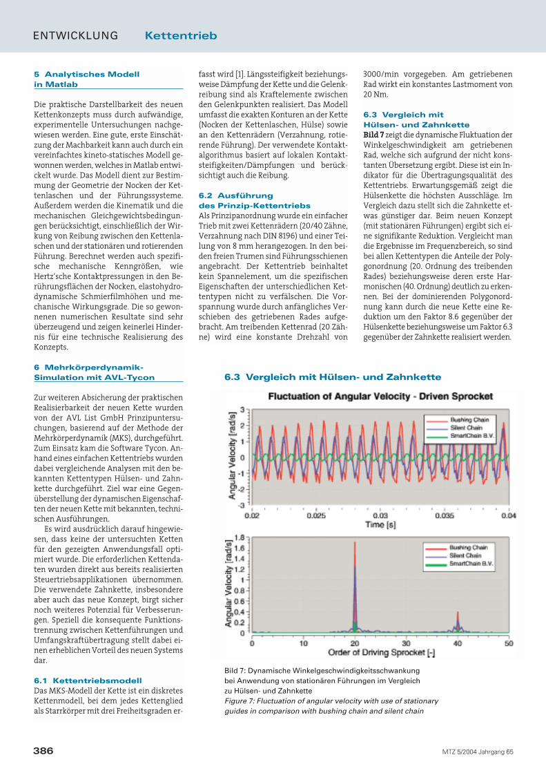
6.3 Vergleich mit Hülsen- und ZahnketteBild 7 zeigt die dynamische Fluktuation derWinkelgeschwindigkeit am getriebenenRad, welche sich aufgrund der nicht kons-tanten Übersetzung ergibt. Diese ist ein In-dikator für die Übertragungsqualität desKettentriebs. Erwartungsgemäß zeigt dieHülsenkette die höchsten Ausschläge. ImVergleich dazu stellt sich die Zahnkette et-was günstiger dar. Beim neuen Konzept(mit stationären Führungen) ergibt sich ei-ne signifikante Reduktion. Vergleicht mandie Ergebnisse im Frequenzbereich, so sindbei allen Kettentypen die Anteile der Poly-gonordnung (20. Ordnung des treibendenRades) beziehungsweise deren erste Har-monischen (40. Ordnung) deutlich zu erken-nen. Bei der dominierenden Polygonord-nung kann durch die neue Kette eine Re-duktion um den Faktor 8.6 gegenüber derHülsenkette beziehungsweise um Faktor 6.3gegenüber der Zahnkette realisiert werden.
ENTWICKLUNG Kettentrieb
386 MTZ 5/2004 Jahrgang 65
6.3 Vergleich mit Hülsen- und Zahnkette
Bild 7: Dynamische Winkelgeschwindigkeitsschwankung bei Anwendung von stationären Führungen im Vergleich zu Hülsen- und ZahnketteFigure 7: Fluctuation of angular velocity with use of stationary guides in comparison with bushing chain and silent chain
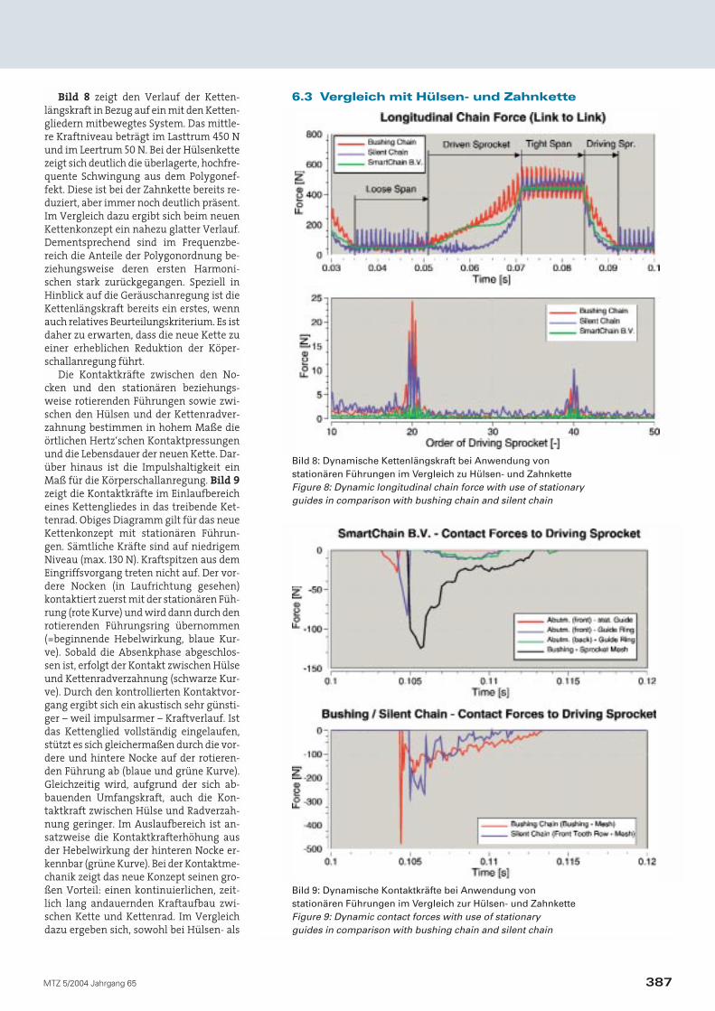
Bild 8 zeigt den Verlauf der Ketten-längskraft in Bezug auf ein mit den Ketten-gliedern mitbewegtes System. Das mittle-re Kraftniveau beträgt im Lasttrum 450 Nund im Leertrum 50 N. Bei der Hülsenkettezeigt sich deutlich die überlagerte, hochfre-quente Schwingung aus dem Polygonef-fekt. Diese ist bei der Zahnkette bereits re-duziert, aber immer noch deutlich präsent.Im Vergleich dazu ergibt sich beim neuenKettenkonzept ein nahezu glatter Verlauf.Dementsprechend sind im Frequenzbe-reich die Anteile der Polygonordnung be-ziehungsweise deren ersten Harmoni-schen stark zurückgegangen. Speziell inHinblick auf die Geräuschanregung ist dieKettenlängskraft bereits ein erstes, wennauch relatives Beurteilungskriterium. Es istdaher zu erwarten, dass die neue Kette zueiner erheblichen Reduktion der Köper-schallanregung führt.
Die Kontaktkräfte zwischen den No-cken und den stationären beziehungs-weise rotierenden Führungen sowie zwi-schen den Hülsen und der Kettenradver-zahnung bestimmen in hohem Maße dieörtlichen Hertz‘schen Kontaktpressungenund die Lebensdauer der neuen Kette. Dar-über hinaus ist die Impulshaltigkeit einMaß für die Körperschallanregung. Bild 9zeigt die Kontaktkräfte im Einlaufbereicheines Kettengliedes in das treibende Ket-tenrad. Obiges Diagramm gilt für das neueKettenkonzept mit stationären Führun-gen. Sämtliche Kräfte sind auf niedrigemNiveau (max. 130 N). Kraftspitzen aus demEingriffsvorgang treten nicht auf. Der vor-dere Nocken (in Laufrichtung gesehen)kontaktiert zuerst mit der stationären Füh-rung (rote Kurve) und wird dann durch denrotierenden Führungsring übernommen(=beginnende Hebelwirkung, blaue Kur-ve). Sobald die Absenkphase abgeschlos-sen ist, erfolgt der Kontakt zwischen Hülseund Kettenradverzahnung (schwarze Kur-ve). Durch den kontrollierten Kontaktvor-gang ergibt sich ein akustisch sehr günsti-ger – weil impulsarmer – Kraftverlauf. Istdas Kettenglied vollständig eingelaufen,stützt es sich gleichermaßen durch die vor-dere und hintere Nocke auf der rotieren-den Führung ab (blaue und grüne Kurve).Gleichzeitig wird, aufgrund der sich ab-bauenden Umfangskraft, auch die Kon-taktkraft zwischen Hülse und Radverzah-nung geringer. Im Auslaufbereich ist an-satzweise die Kontaktkrafterhöhung ausder Hebelwirkung der hinteren Nocke er-kennbar (grüne Kurve). Bei der Kontaktme-chanik zeigt das neue Konzept seinen gro-ßen Vorteil: einen kontinuierlichen, zeit-lich lang andauernden Kraftaufbau zwi-schen Kette und Kettenrad. Im Vergleichdazu ergeben sich, sowohl bei Hülsen- als
387MTZ 5/2004 Jahrgang 65
6.3 Vergleich mit Hülsen- und Zahnkette
Bild 8: Dynamische Kettenlängskraft bei Anwendung von stationären Führungen im Vergleich zu Hülsen- und ZahnketteFigure 8: Dynamic longitudinal chain force with use of stationary guides in comparison with bushing chain and silent chain
Bild 9: Dynamische Kontaktkräfte bei Anwendung von stationären Führungen im Vergleich zur Hülsen- und ZahnketteFigure 9: Dynamic contact forces with use of stationary guides in comparison with bushing chain and silent chain
auch Zahnkette, die typischen Kraftspit-zen, hervorgerufen durch den Einlaufstoß,Bild 9, unteres Diagramm.
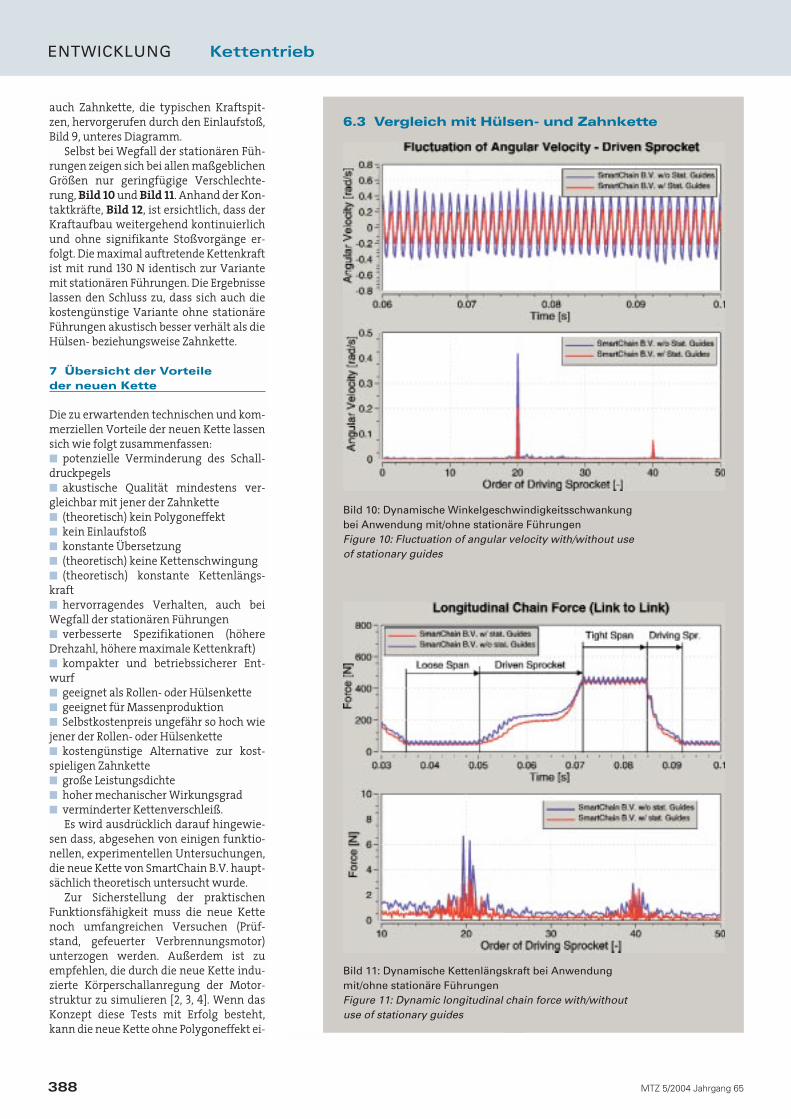
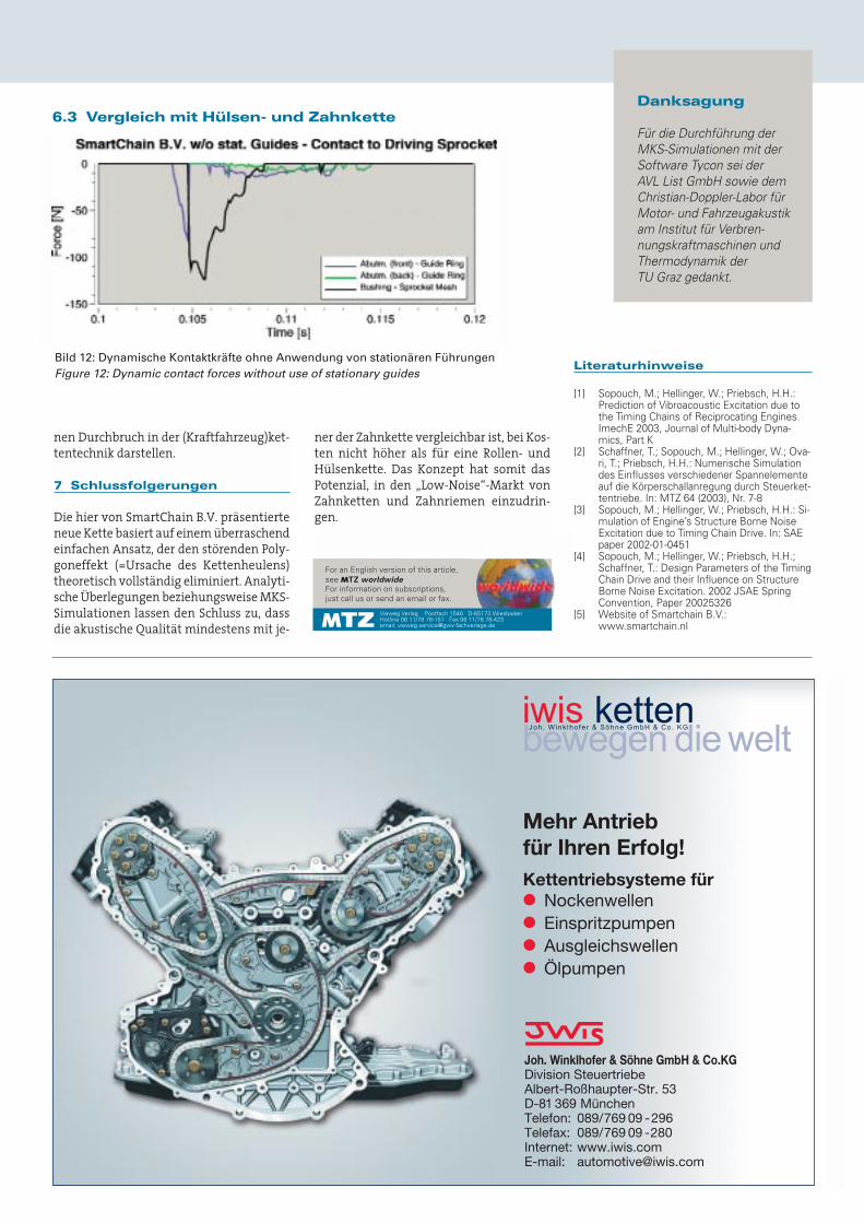
Selbst bei Wegfall der stationären Füh-rungen zeigen sich bei allen maßgeblichenGrößen nur geringfügige Verschlechte-rung, Bild 10 und Bild 11. Anhand der Kon-taktkräfte, Bild 12, ist ersichtlich, dass derKraftaufbau weitergehend kontinuierlichund ohne signifikante Stoßvorgänge er-folgt. Die maximal auftretende Kettenkraftist mit rund 130 N identisch zur Variantemit stationären Führungen. Die Ergebnisselassen den Schluss zu, dass sich auch diekostengünstige Variante ohne stationäreFührungen akustisch besser verhält als dieHülsen- beziehungsweise Zahnkette.
7 Übersicht der Vorteile der neuen Kette
Die zu erwartenden technischen und kom-merziellen Vorteile der neuen Kette lassensich wie folgt zusammenfassen:■ potenzielle Verminderung des Schall-druckpegels■ akustische Qualität mindestens ver-gleichbar mit jener der Zahnkette■ (theoretisch) kein Polygoneffekt■ kein Einlaufstoß■ konstante Übersetzung■ (theoretisch) keine Kettenschwingung■ (theoretisch) konstante Kettenlängs-kraft■ hervorragendes Verhalten, auch beiWegfall der stationären Führungen■ verbesserte Spezifikationen (höhereDrehzahl, höhere maximale Kettenkraft)■ kompakter und betriebssicherer Ent-wurf■ geeignet als Rollen- oder Hülsenkette■ geeignet für Massenproduktion■ Selbstkostenpreis ungefähr so hoch wiejener der Rollen- oder Hülsenkette■ kostengünstige Alternative zur kost-spieligen Zahnkette■ große Leistungsdichte■ hoher mechanischer Wirkungsgrad■ verminderter Kettenverschleiß.
Es wird ausdrücklich darauf hingewie-sen dass, abgesehen von einigen funktio-nellen, experimentellen Untersuchungen,die neue Kette von SmartChain B.V. haupt-sächlich theoretisch untersucht wurde.
Zur Sicherstellung der praktischenFunktionsfähigkeit muss die neue Kettenoch umfangreichen Versuchen (Prüf-stand, gefeuerter Verbrennungsmotor)unterzogen werden. Außerdem ist zuempfehlen, die durch die neue Kette indu-zierte Körperschallanregung der Motor-struktur zu simulieren [2, 3, 4]. Wenn dasKonzept diese Tests mit Erfolg besteht,kann die neue Kette ohne Polygoneffekt ei-
ENTWICKLUNG Kettentrieb
388 MTZ 5/2004 Jahrgang 65
6.3 Vergleich mit Hülsen- und Zahnkette
Bild 10: Dynamische Winkelgeschwindigkeitsschwankung bei Anwendung mit/ohne stationäre FührungenFigure 10: Fluctuation of angular velocity with/without use of stationary guides
Bild 11: Dynamische Kettenlängskraft bei Anwendung mit/ohne stationäre FührungenFigure 11: Dynamic longitudinal chain force with/without use of stationary guides
nen Durchbruch in der (Kraftfahrzeug)ket-tentechnik darstellen.
7 Schlussfolgerungen
Die hier von SmartChain B.V. präsentierteneue Kette basiert auf einem überraschendeinfachen Ansatz, der den störenden Poly-goneffekt (=Ursache des Kettenheulens)theoretisch vollständig eliminiert. Analyti-sche Überlegungen beziehungsweise MKS-Simulationen lassen den Schluss zu, dassdie akustische Qualität mindestens mit je-
6.3 Vergleich mit Hülsen- und Zahnkette
Bild 12: Dynamische Kontaktkräfte ohne Anwendung von stationären FührungenFigure 12: Dynamic contact forces without use of stationary guides
Danksagung
Für die Durchführung derMKS-Simulationen mit derSoftware Tycon sei der AVL List GmbH sowie demChristian-Doppler-Labor fürMotor- und Fahrzeugakustikam Institut für Verbren-nungskraftmaschinen undThermodynamik der TU Graz gedankt.
For an English version of this article,see MTZ worldwide
For information on subscriptions, just call us or send an email or fax.
Vieweg Verlag Postfach 1546 D-65173 WiesbadenHotline 06 11/78 78-151 Fax 06 11/78 78-423email: [email protected]
Kettentriebsysteme für● Nockenwellen● Einspritzpumpen● Ausgleichswellen● Ölpumpen
Joh. Winklhofer & Söhne GmbH & Co.KGDivision SteuertriebeAlbert-Roßhaupter-Str. 53D-81 369 MünchenTelefon: 089/769 09 -296Telefax: 089/769 09 -280Internet: www.iwis.comE-mail: [email protected]
Mehr Antrieb für Ihren Erfolg!
ner der Zahnkette vergleichbar ist, bei Kos-ten nicht höher als für eine Rollen- undHülsenkette. Das Konzept hat somit dasPotenzial, in den „Low-Noise“-Markt vonZahnketten und Zahnriemen einzudrin-gen.
Literaturhinweise
[1] Sopouch, M.; Hellinger, W.; Priebsch, H.H.:Prediction of Vibroacoustic Excitation due tothe Timing Chains of Reciprocating Engines.ImechE 2003, Journal of Multi-body Dyna-mics, Part K
[2] Schaffner, T.; Sopouch, M.; Hellinger, W.; Ova-ri, T.; Priebsch, H.H.: Numerische Simulationdes Einflusses verschiedener Spannelementeauf die Körperschallanregung durch Steuerket-tentriebe. In: MTZ 64 (2003), Nr. 7-8
[3] Sopouch, M.; Hellinger, W.; Priebsch, H.H.: Si-mulation of Engine’s Structure Borne NoiseExcitation due to Timing Chain Drive. In: SAEpaper 2002-01-0451
[4] Sopouch, M.; Hellinger, W.; Priebsch, H.H.;Schaffner, T.: Design Parameters of the TimingChain Drive and their Influence on StructureBorne Noise Excitation. 2002 JSAE SpringConvention, Paper 20025326
[5] Website of Smartchain B.V.:www.smartchain.nl
DEVELOPMENT Chain Drive
2 MTZ worldwide 5/2004 Volume 65
Chain drives in modern internal combustion engines frequently induce a disturbing noise,so-called whine noise. Basically, this noise is caused by the chordal action or polygon ef-fect that originates from the periodically changing effective radius of the sprockets. In thisarticle, SmartChain B.V. presents a new roller chain or bushing chain that entirely avoidsthe disturbing polygon effect. The concept was evaluated by AVL List GmbH, using themulti-body dynamics software Tycon.
1 Introduction
The polygon effect is one of the main caus-es of the relatively high noise and vibrationlevel of roller chains and bushing chains.Besides the excitation of longitudinal andtransversal vibrations of the chain spans,meshing impacts between the chain linksand the sprocket mesh occur. The noise ex-citation induced by the polygon effect usu-ally occurs predominantly at the meshingfrequency of the chain drive (= polygon fre-
quency). If this frequency coincides with anatural frequency of the structure of theengine, resonance occurs which leads to anadditional increase in the level of structure-borne noise. The resulting disturbing noiseis known as whine noise.
Silent chains have more favourableacoustic properties than roller chains orbushing chains due to their specific contactkinematics. Compared to the bushing chainhowever, their cost price is at least twice ashigh. In addition, the use of silent chains in
By Theo Korse and
Martin Sopouch
Eine neue Steuerkette
ohne Polygoneffekt
You will find the figures mentioned in this article in the German issue of MTZ 5/2004 beginning on page xxx.
A New Timing Chainwith No Chordal Action
3MTZ worldwide 5/2004 Volume 65
heavily loaded timing chain drives, such asin direct injection diesel engines, is hardlypossible.
Synchronous belts generally show verygood acoustic behaviour, but their lifetimeis unacceptably short, in particular if usedin diesel engines. Therefore, there is a realneed for a durable, low-noise, low-costroller chain drive or bushing chain drivewithout a disturbing polygon effect.
2 A New Chain with NoPolygon Effect
The new chain from SmartChain B.V. [5] is adurable, low-cost roller chain or bushingchain that does not show a polygon effect.Meshing impacts between the chain andsprocket no longer occur and the actualspeed ratio is totally constant. From a theo-retical point of view, it is expected that thenoise and vibration level of the new chainis at least as favourable as that of the silentchain. The new ideas of SmartChain B.V.have been protected by internationalpatent applications. The new chain may beapplied, for instance, in the (timing) chaindrive of the camshaft(s), injector pump, bal-ancer shaft or oil pump of an internal com-bustion engine.
3 Theory
The theory behind the “zero polygon effect”of this new innovative chain is surprisinglysimple. It is based on elementary kinemat-ic principles and is therefore considered tobe conclusive.
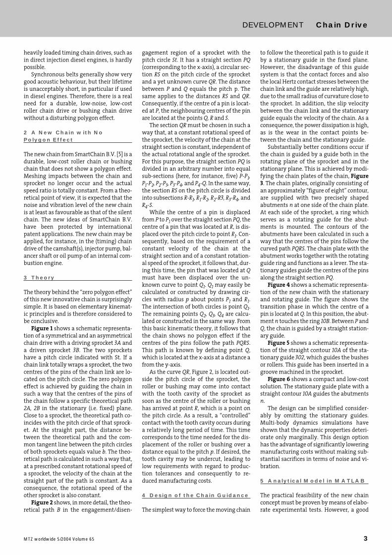
Figure 1 shows a schematic representa-tion of a symmetrical and an asymmetricalchain drive with a driving sprocket 3A anda driven sprocket 3B. The two sprocketshave a pitch circle indicated with St. If achain link totally wraps a sprocket, the twocentres of the pins of the chain link are lo-cated on the pitch circle. The zero polygoneffect is achieved by guiding the chain insuch a way that the centres of the pins ofthe chain follow a specific theoretical path2A, 2B in the stationary (i.e. fixed) plane.Close to a sprocket, the theoretical path co-incides with the pitch circle of that sprock-et. At the straight part, the distance be-tween the theoretical path and the com-mon tangent line between the pitch circlesof both sprockets equals value b. The theo-retical path is calculated in such a way that,at a prescribed constant rotational speed ofa sprocket, the velocity of the chain at thestraight part of the path is constant. As aconsequence, the rotational speed of theother sprocket is also constant.
Figure 2 shows, in more detail, the theo-retical path B in the engagement/disen-
gagement region of a sprocket with thepitch circle St. It has a straight section PQ(corresponding to the x-axis), a circular sec-tion RS on the pitch circle of the sprocketand a yet unknown curve QR. The distancebetween P and Q equals the pitch p. Thesame applies to the distances RS and QR.Consequently, if the centre of a pin is locat-ed at P, the neighbouring centres of the pinare located at the points Q, R and S.
The section QR must be chosen in such away that, at a constant rotational speed ofthe sprocket, the velocity of the chain at thestraight section is constant, independent ofthe actual rotational angle of the sprocket.For this purpose, the straight section PQ isdivided in an arbitrary number into equalsub-sections (here, for instance, five) P-P1,P1-P2, P2-P3, P3-P4, and P4-Q. In the same way,the section RS on the pitch circle is dividedinto subsections R-R1, R1-R2, R2-R3, R3-R4, andR4-S.
While the centre of a pin is displacedfrom P to P1 over the straight section PQ, thecentre of a pin that was located at R, is dis-placed over the pitch circle to point R1. Con-sequently, based on the requirement of aconstant velocity of the chain at thestraight section and of a constant rotation-al speed of the sprocket, it follows that, dur-ing this time, the pin that was located at Qmust have been displaced over the un-known curve to point Q1. Q1 may easily becalculated or constructed by drawing cir-cles with radius p about points P1 and R1.The intersection of both circles is point Q1.The remaining points Q2, Q3, Q4 are calcu-lated or constructed in the same way. Fromthis basic kinematic theory, it follows thatthe chain shows no polygon effect if thecentres of the pins follow the path PQRS.This path is known by defining point Q,which is located at the x-axis at a distance afrom the y-axis.
As the curve QR, Figure 2, is located out-side the pitch circle of the sprocket, theroller or bushing may come into contactwith the tooth cavity of the sprocket assoon as the centre of the roller or bushinghas arrived at point R, which is a point onthe pitch circle. As a result, a “controlled”contact with the tooth cavity occurs duringa relatively long period of time. This timecorresponds to the time needed for the dis-placement of the roller or bushing over adistance equal to the pitch p. If desired, thetooth cavity may be undercut, leading tolow requirements with regard to produc-tion tolerances and consequently to re-duced manufacturing costs.
4 Design of the Chain Guidance
The simplest way to force the moving chain
to follow the theoretical path is to guide itby a stationary guide in the fixed plane.However, the disadvantage of this guidesystem is that the contact forces and alsothe local Hertz contact stresses between thechain link and the guide are relatively high,due to the small radius of curvature close tothe sprocket. In addition, the slip velocitybetween the chain link and the stationaryguide equals the velocity of the chain. As aconsequence, the power dissipation is high,as is the wear in the contact points be-tween the chain and the stationary guide.
Substantially better conditions occur ifthe chain is guided by a guide both in therotating plane of the sprocket and in thestationary plane. This is achieved by modi-fying the chain plates of the chain, Figure3. The chain plates, originally consisting ofan approximately “figure of eight” contour,are supplied with two precisely shapedabutments n at one side of the chain plate.At each side of the sprocket, a ring whichserves as a rotating guide for the abut-ments is mounted. The contours of theabutments have been calculated in such away that the centres of the pins follow thecurved path PQRS. The chain plate with theabutment works together with the rotatingguide ring and functions as a lever. The sta-tionary guides guide the centres of the pinsalong the straight section PQ.
Figure 4 shows a schematic representa-tion of the new chain with the stationaryand rotating guide. The figure shows thetransition phase in which the centre of apin is located at Q. In this position, the abut-ment n touches the ring 10B. Between P andQ, the chain is guided by a straight station-ary guide.
Figure 5 shows a schematic representa-tion of the straight contour 10A of the sta-tionary guide 302, which guides the bushesor rollers. This guide has been inserted in agroove machined in the sprocket.
Figure 6 shows a compact and low-costsolution. The stationary guide plate with astraight contour 10A guides the abutmentsn.
The design can be simplified consider-ably by omitting the stationary guides.Multi-body dynamics simulations haveshown that the dynamic properties deteri-orate only marginally. This design optionhas the advantage of significantly loweringmanufacturing costs without making sub-stantial sacrifices in terms of noise and vi-bration.
5 Analytical Model in MATLAB
The practical feasibility of the new chainconcept must be proven by means of elabo-rate experimental tests. However, a good
DEVELOPMENT Chain Drive
4 MTZ worldwide 5/2004 Volume 65
first assessment of the feasibility of thenew chain may also be acquired by meansof a simplified kineto-static model of theSmartChain concept. For this purpose, ananalytical model has been generated inMATLAB.
The model is used to calculate the re-quired geometry of the abutments of thechain plates and the guide systems. In addi-tion, the kinematics and the mechanicalequilibrium conditions, including the effectof friction between the chain links and thestationary guide and the rotating guide, areconsidered. The model calculates specificmechanical parameters such as Hertz con-tact stresses at the contact area of the abut-ments, elasto-hydrodynamic oil film thick-nesses and mechanical efficiencies. The nu-merical results are very convincing and donot present an obstacle for the technicalimplementation of the new concept.
6 Multi-Body DynamicsSimulation using AVL-Tycon
In order to further increase the certaintyabout the practical feasibility of the newchain, AVL List GmbH performed basic in-vestigations based on the method of multi-body dynamics (MBD). The software Tyconwas used for this purpose. Based on a sim-ple chain drive, comparative analyses withthe common chain types bushing chainand silent chain were performed. The aimwas a comparison of the dynamic proper-ties of the new chain with those of knowntechnical implementations.
It must be emphasized that none of theinvestigated chains were optimised for thepresent application. The required data ofthe chain were taken directly from alreadyimplemented timing chain applications.The silent chain, and in particular the newchain concept, certainly have further po-tential for improvement. Specifically, theconsistent separation of functions betweenchain guidance and transmission of the cir-cumferential force represents a consider-able advantage of the new chain system.
6.1 MBD Model of the ChainThe multi-body dynamics model of the
chain is a discrete chain model in whichevery chain link is considered as a rigidbody with three degrees of freedom [1]. Lon-gitudinal stiffness, damping of the chainand the friction in the joints are consideredas force elements between the centres ofthe joints. The model comprises the exactcontours of the chain (abutments of thechain plates, bushing) as well as those ofthe sprockets (sprocket mesh, rotatingguide). The contact algorithm used is basedon the local contact stiffness/damping, andalso considers friction.
6.2 Layout of the Chain DriveA simple drive with two sprockets (20/40teeth, sprocket mesh according to DIN 8196)and a pitch of 8 mm, which is typical of tim-ing chain applications, was used as a basicconfiguration. Guides were positioned inboth free spans. The chain drive does notinclude a tensioning device in order to pre-vent adulteration of the specific propertiesof the various chain types. The initial pre-load of the chain was created by adjustingthe driven sprocket. The driving sprocket(20 teeth) has a prescribed constant rota-tional speed of 3000 rpm. The drivensprocket is loaded by a constant moment of20 Nm.
6.3 Comparison with a BushingChain and a Silent ChainFigure 7 shows the dynamic fluctuation ofthe angular velocity of the driven sprocket,which is not constant due to the non-con-stant speed ratio. This fluctuation is an in-dicator of the quality of the speed ratio ofthe chain drive. As expected, the bushingchain shows the highest amplitudes,whereas the silent chain shows a some-what improved behaviour. The new chainconcept (variant with stationary guides),however, shows a significant reduction inthe respective amplitudes. If the results inthe frequency domain are compared, allchain types clearly show the componentsof the polygon order (20th order of the dri-ving sprocket) or its first harmonic (40th or-der). Considering the dominating polygonorder, the new chain achieves a reductionby a factor of 8.6 compared to the bushingchain and by a factor of 6.3 compared to thesilent chain.
Figure 8 shows the longitudinal chainforce in relation to an observer framewhich moves with the chain links. The av-erage force level is 450 N in the tight spanand 50 N in the loose span. For the bushingchain, the superimposed, high-frequencyvibration due to the chordal action can beclearly seen. For the silent chain, this vibra-tion has been reduced, but is still distinctlypresent. In contrast to this, the new chainconcept shows an almost smooth curve. Inthe frequency domain, it is shown that thecomponents of the polygon order, or thoseof its first harmonic, are now very small. Inparticular, with regard to noise excitation,the longitudinal chain force is a first, albeitrelative, criterion for assessment. There-fore, it is to be expected that the new chainwill lead to a significant reduction in noiseexcitation.
The contact forces between the abut-ments and the stationary or rotatingguides, but also those between the bush-ings and the sprocket mesh, determine
both the local Hertz contact stress and thelifetime of the new chain to a considerableextent. In addition, the magnitude of theimpulse of these forces determines the in-tensity of the excitation of structure-bornenoise. Figure 9 shows the contact forces be-tween the chain link and the drivingsprocket in the engagement region. Thepicture at the top applies to the new con-cept with stationary guides. All forces are ata low level (maximum 130 N). Peak forcesdue to the meshing impacts do not occur.Furthermore, it can be observed that, firstof all, the abutment at the front side (seenin the running direction) makes contactwith the stationary guide (red curve). Next,the contact is taken over by the rotatingguide (= starting action of the lever, bluecurve). As soon as the descending phase iscomplete, the contact between the bushingand the sprocket mesh follows (blackcurve). Due to the controlled meshingprocess, an acoustically very favourableforce transfer occurs, as a result of the lowimpulse. As soon as the chain link has total-ly wrapped the sprocket, the chain link ispositioned by the front and rear abutmentof the chain plate, which are both support-ed by the rotating guide. During thisprocess, the circumferential force decreasesand, as a consequence, the contact force be-tween the bushing and the sprocket meshdecreases simultaneously. In the disen-gagement region, the increase in the con-tact force, due to the lever action of the rearabutment, can still be seen to some extent(green curve). The new concept shows itsmajor advantage especially with regard tocontact mechanics: a continuous, long-last-ing force build-up occurs between thechain and the sprocket mesh. In contrast,the picture at the bottom of Figure 9 showsthe corresponding curve of the contactforce of the bushing chain and the silentchain. These chains show the typical forcepeaks caused by the meshing impact.
Even when the stationary guides areomitted, all important parameters showonly a minor deterioration, Figure 10 andFigure 11. With regard to the contact forcesbetween the chain plate/bushing and thesprocket mesh, Figure 12, it is clear that theforce build-up occurs continuously andwithout impact phenomena. The maxi-mum chain force is about 130 N, which is al-most identical to the variant with station-ary guides. The results allow the conclusionthat the low-cost variant without station-ary guides also behaves significantly betteracoustically than the bushing chain andsilent chain.
7 Overview of the Advantagesof the New Chain
DEVELOPMENT Chain Drive
5MTZ worldwide 5/2004 Volume 65
In short, the technical and commercial ad-vantages expected of the new chain are:■ potential reduction in the noise level■ acoustic quality at least equal to that ofsilent chains■ (theoretically) no polygon effect■ no meshing impact■ constant actual speed ratio■ (theoretically) no chain vibration■ (theoretically) constant longitudinalchain force■ excellent behaviour even if stationaryguides are omitted■ improved specifications (higher speed,higher maximum chain load)■ compact and reliable design■ suitable as a roller chain or a bushingchain■ suitable for mass production■ manufacturing price about equal toroller chains or bushing chains■ potential low-cost alternative for expen-sive silent chains■ high power density■ high mechanical efficiency■ reduced chain wear
It should be emphasized that, apart fromsome functional experimental tests, thenew chain from SmartChain B.V. has main-ly been investigated on a theoretical basis.
In order to be totally certain about thereal feasibility, the new chain still has to besubjected to extensive experimental tests(test bench, fired engine). In addition, it isnecessary to perform a simulation of thestructure-borne noise excitation of the in-ternal combustion engine resulting fromthe new chain [2, 3, 4]. If the new conceptpasses these tests successfully, the newchain with no polygon effect can become abreakthrough in (automotive)chain engi-neering.
8 Conclusions
The new chain from SmartChain B.V. withno polygon effect is based on a surprisinglysimple approach and has an acoustic quali-ty that is at least equal to that of the silentchain. Its manufacturing price is not higherthan that of a roller chain or a bushingchain. The new chain has the potential topenetrate and expand on the “low-noise”market of automotive silent chains andsynchronous belts.
References
[1] Sopouch, M.; Hellinger, W.; Priebsch, H.H.:Prediction of Vibroacoustic Excitation due to the Timing Chains of Recip-rocating Engines, ImechE 2003, Journal ofMulti-body Dynamics, Part K
[2] Schaffner, T.; Sopouch, M.; Hellinger, W.;Ovari, T.; Priebsch, H.H.: Numerische Simula-tion des Einflusses verschiedener Spannele-mente auf die Körperschallanregung durch
Steuerkettentriebe In: MTZ 64 (2003), Nr. 7-8[3] Sopouch, M.; Hellinger, W.; Priebsch, H.H.:
Simulation of Engine’s Structure Borne NoiseExcitation due to Timing Chain Drive. In: SAEpaper 2002-01-0451
[4] Sopouch, M.; Hellinger, W.; Priebsch, H.H.;Schaffner, T.: Design Parameters of the Tim-ing Chain Drive and their Influence on Struc-ture Borne Noise Excitation, 2002 JSAE SpringConvention, Paper 20025326
[5] Website of Smartchain B.V.:www.smartchain.nl
((Bildunterschriften))Figure 1: Theoretical path of symmetricaland asymmetrical chain driveFigure 2: Calculation of the theoretical pathof the new chain with a zero polygon effectFigure 3: The new chain with two abut-ments per chain plateFigure 4: The new chain guided by the sta-tionary and rotating guideFigure 5: Design option in which the rollersor bushings are guided by a straight con-tour 10AFigure 6: Design option in which the abut-ments are guided by a straight contour 10AFigure 7: Fluctuation of angular velocitywith the use of stationary guides comparedto bushing chains and silent chainsFigure 8: Dynamic longitudinal chain forcewith the use of stationary guides comparedto bushing chains and silent chainsFigure 9: Dynamic contact forces with theuse of stationary guides compared to bush-ing chains and silent chainsFigure 10: Fluctuation of angular velocitywith and without the use of stationaryguidesFigure 11: Dynamic longitudinal chain forcewith and without the use of stationaryguidesFigure 12: Dynamic contact forces withoutthe use of stationary guides
AcknowledgementsSmartChain B.V. is greatly indebted to
AVL List GmbH and the Christian-Doppler-Laboratory for Engine and VehicleAcoustics of the Institute for Internal Com-bustion Engines and Thermodynamics ofthe Graz University of Technology for per-forming the multi-body dynamics simula-tions with the software Tycon.
DEVELOPMENT Chain Drive