Embed Size (px)
Citation preview
EISHO TEK
Vacuum Circuit Breaker
〔TYPE:SV1-12〕
INSTRUCTION MANUAL
〔Operation and Maintenance Version〕
TAIWAN CALSONIC
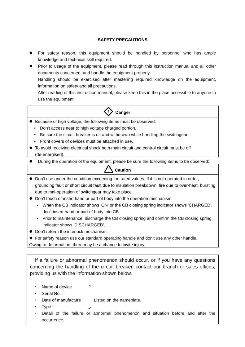
SAFETY PRECAUTIONS
� For safety reason, this equipment should be handled by personnel who has ample
knowledge and technical skill required.
� Prior to usage of the equipment, please read through this instruction manual and all other
documents concerned, and handle the equipment properly.
Handling should be exercised after mastering required knowledge on the equipment,
information on safety and all precautions.
After reading of this instruction manual, please keep this in the place accessible to anyone to
use the equipment.
� During the operation of the equipment, please be sure the following items to be observed:
Danger
� Because of high voltage, the following items must be observed:
• Don't access near to high voltage charged portion.
• Be sure the circuit breaker is off and withdrawn while handling the switchgear.
• Front covers of devices must be attached in use.
� To avoid receiving electrical shock both main circuit and control circuit must be off
(de-energised).
Caution
� Don't use under the condition exceeding the rated values. If it is not operated in order,
grounding fault or short circuit fault due to insulation breakdown, fire due to over-heat, bursting
due to mal-operation of switchgear may take place.
� Don't touch or insert hand or part of body into the operation mechanism.
• When the CB indicator shows 'ON' or the CB closing spring indicator shows 'CHARGED',
don't insert hand or part of body into CB.
• Prior to maintenance, discharge the CB closing spring and confirm the CB closing spring
indicator shows 'DISCHARGED'.
� Don't reform the interlock mechanism.
� For safety reason use our standard operating handle and don't use any other handle.
Owing to deformation, there may be a chance to invite injury.
If a failure or abnormal phenomenon should occur, or if you have any questions concerning the handling of the circuit breaker, contact our branch or sales offices, providing us with the information shown below.
・ Name of device
・ Serial No.
・ Date of manufacture Listed on the nameplate.
・ Type
・ Detail of the failure or abnormal phenomenon and situation before and after the
occurrence.
!
!
CONTENTS
1. RATING AND OUTLINE DRAWING
1-1 Ratings ····································································································· 1
1-2 Outline drawing ·························································································· 2
1-3 Internal connection diagram ·········································································· 3
2. DESCRIPTION ·························································································· 4
3. MANUAL OPERATION (Manual stored energy type and stored energy type) ···· 5
3-1 Charging ··································································································· 5
3-2 Closing ····································································································· 5
3-3 Opening ···································································································· 5
3-4 Putting into “SERVICE” and “ISOLATED” operation ··········································· 5
4. UNLOADING AND PREPARATION FOR OPERATION
4-1 Unloading ································································································· 7
4-2 Unpacking ································································································· 7
4-3 Transportation ···························································································· 7
4-4 Checking after unpacking ············································································· 8
4-5 Storage ····································································································· 8
4-6 Inspection during storage ············································································· 8
4-7 Installation ································································································· 8
4-8 Inspection and procedure before operation ······················································ 8
5. MAINTENANCE AND INSPECTION
5-1 Caution at inspection ··················································································· 9
5-2 Patrol inspection ························································································· 9
5-3 Periodical inspection ··················································································· 9
5-4 Detail inspection ························································································· 14
5-5 Special inspection ······················································································· 15
5-6 Trouble shootings ······················································································· 15
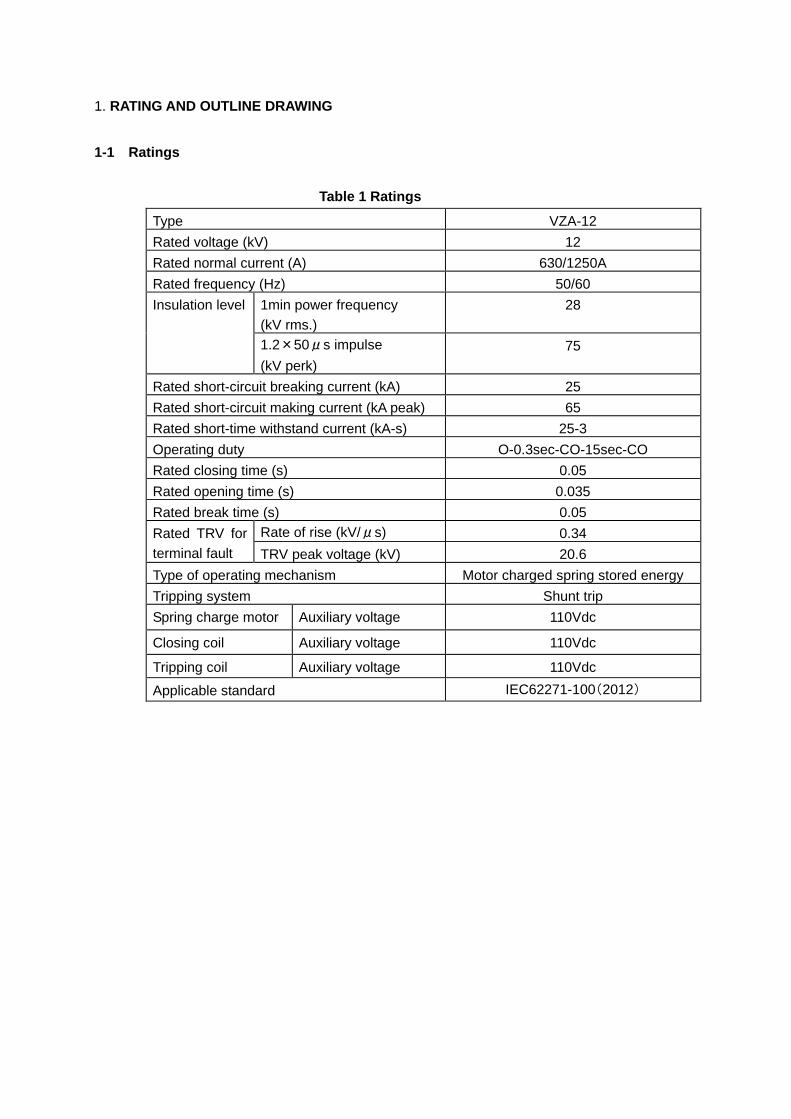
1. RATING AND OUTLINE DRAWING
1-1 Ratings
Table 1 Ratings
Type VZA-12
Rated voltage (kV) 12
Rated normal current (A) 630/1250A
Rated frequency (Hz) 50/60
Insulation level 1min power frequency (kV rms.)
28
1.2×50μs impulse
(kV perk) 75
Rated short-circuit breaking current (kA) 25
Rated short-circuit making current (kA peak) 65
Rated short-time withstand current (kA-s) 25-3
Operating duty O-0.3sec-CO-15sec-CO
Rated closing time (s) 0.05
Rated opening time (s) 0.035
Rated break time (s) 0.05
Rated TRV for terminal fault
Rate of rise (kV/μs) 0.34
TRV peak voltage (kV) 20.6
Type of operating mechanism Motor charged spring stored energy
Tripping system Shunt trip
Spring charge motor Auxiliary voltage 110Vdc
Closing coil Auxiliary voltage 110Vdc
Tripping coil Auxiliary voltage 110Vdc
Applicable standard IEC62271-100(2012)
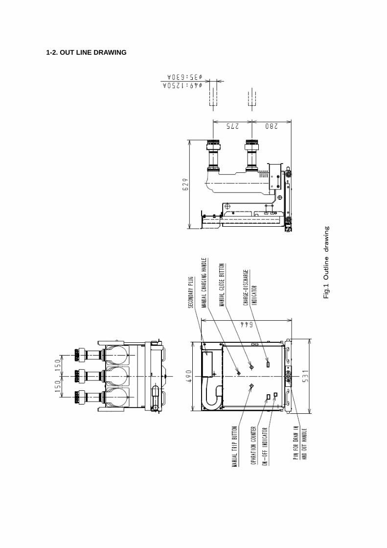
1-2. OUT LINE DRAWING
Fig
.1 O
utlin
e
dra
win
g
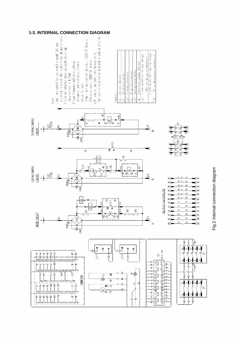
1-3. INTERNAL CONNECTION DIAGRAM
Fig
.2 In
tern
al c
onne
ctio
n di
agra
m
2. DESCRIPTION
The Meidensha VZA-12 vacuum circuit breaker employs the vacuum interrupter which has
excellent interruption efficiency.
The vacuum circuit breaker is extremely reliable in service, require only a minimum of
maintenance and have a long life expectancy.
The Meidensha VZA-12 vacuum circuit breaker meets the requirements of IEC62771-100.
Closing spring can be charged motor..
The three breaker poles with vacuum interrupter, are mounted on a common truck housing.
The moving contacts in vacuum interrupters are opened and closed by springs.
In order to ensure the maximum performance and dependable operation, it is suggested that
the operator reads this instruction manual carefully to be well acquainted with all the features
of this vacuum circuit breaker.
Safety precaution
This circuit breaker uses powerful springs for operation. Prior to the inspection of open/closing
characteristics and the parts replacement work, the vacuum circuit breaker shall be operated to
be the following conditions. ・VCB status “OFF”
・Closing spring “DISCHARGED”
・Control and motor circuits “OPEND”
3. MANUAL OPERATION(Manual stored energy type and Motor stored energy type)
Motor-operated vacuum circuit breakers can be actuated by hand if the control supply should
fail.
3-1. Charging (See Fig.3)
Insert the charging handle to the manual charging shaft and clockwise until a clicking sound
is heard. At this time the charge-discharge indicator shows “CHARGED”.
The operator is protected for any risk when sudden recovery of control source during
charging by a preventive device charging handle.
3-2. Closing (See Fig.3)
Press the manual close button to close the vacuum circuit breaker.
The ON-OFF indicator will show “ON” and the charge-discharge indicator will show
“DISCHARGED”.
The closing spring is automatically recharged by the motor mechanism immediately after the
breaker is closed.
On-hand operated breakers, the closing can be recharged by hand.
3-3. Opening (See Fig.3)
The tripping spring is charged during closing operation.
Press the manual trip button to open the vacuum circuit breaker.
The ON-OFF indicator will show “OFF”.
3-4. Putting into “SERVICE” and “ISOLATED” operatio n (See Fig.3,4)
When setting the VCB in switchgear, use the following procedure.
(1) Confirm the VCB is “OFF” position.
(2) Slide the VCB handle inward.
(3) Insert the VCB into switchgear.
(4) Confirm the VCB is located in proper position.
(5) Slide the VCB handle outward.
(6) Connect the cable connector.
When setting the VCB from the ISOLATED to the SERVICE position, use the following
procedures.
(1) Confirm the VCB is “OFF” position.
(2) Insert the draw out handle to the shaft for draw in and out, and rotate clockwise until a
clicking sound is heard. This position is SERVICE position.
(3) When the vacuum circuit breaker is set from the SERVICE to the ISOLATED position,
insert the draw out handle into the VCB shaft and rotate un-clockwise until a clicking
sound is heard. This position is ISOLATED position.
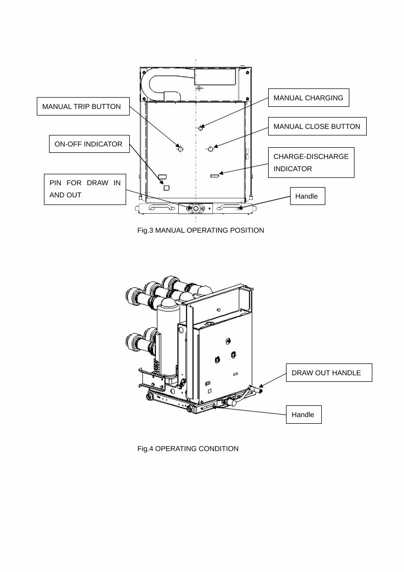
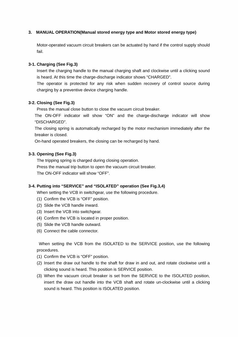
Fig.3 MANUAL OPERATING POSITION
Fig.4 OPERATING CONDITION
ON-OFF INDICATOR
CHARGE-DISCHARGE
INDICATOR
MANUAL TRIP BUTTON
MANUAL CLOSE BUTTON
MANUAL CHARGING
PIN FOR DRAW IN
AND OUT Handle
DRAW OUT HANDLE
Handle
4. UNLOADING AND PREPARATION FOR OPERATION
4-1. Unloading
Use crane or fork lift, operate it slowly not to give any shock to the vacuum circuit breaker.
4-2. Unpacking
It is recommended unpack the circuit breaker earlier when it is arrived.
Be careful, not to damage the circuit breaker especially insulating material, vacuum
interrupters, main circuit connectors and front panel.
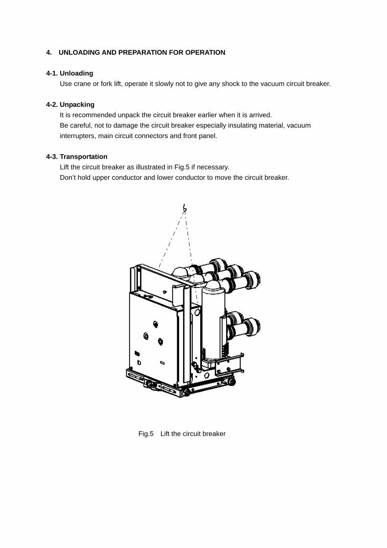
4-3. Transportation
Lift the circuit breaker as illustrated in Fig.5 if necessary.
Don’t hold upper conductor and lower conductor to move the circuit breaker.
Fig.5 Lift the circuit breaker
4-4. Checking after unpacking
Check the following and report to Meidensha or representing organization when any defect is
found.
(1). Quantity, Type, Ratings and etc.
(2). Damages such as bends, cut and serious scratches.
(3). Loss or loose fitting of bolts and nuts.
(4). Quantity and Type of accessories and spare parts it any.
4-5. Storage
It is recommended to put the circuit breaker into operation as soon as possible after
unpacking.
However, if storage is un-avoidable, the followings shall be observed.
(1). Store unpacked.
(2). Store indoor on flat floor, in clean and dry atmosphere without corrosive gas, water and
dust (especially cement dust).
(3). Cover with plastic sheet to protect dust, small animals, insects especially spiders
invasion.
(4). Open circuit Breaker and release closing spring.
4-6. Inspection during storage
If longer storage is un-avoidable, check the followings yearly.
(1). Rust, if any remove it.
(2). Dust, dirt and spider web on surface of insulating material, if any clean with dry clean
cloth.
(3). Loss or loose fitting of bolts and nuts, and damages.
4-7. Installation
(1). Confirm the circuit breaker is open and closing spring is discharged with respective
mechanical indicator.
(2). Check the circuit breaker following to the previous Item 4-6.
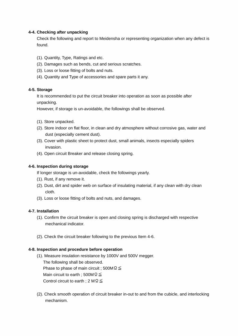
4-8. Inspection and procedure before operation
(1). Measure insulation resistance by 1000V and 500V megger.
The following shall be observed. Phase to phase of main circuit ; 500MΩ≦
Main circuit to earth ; 500MΩ≦
Control circuit to earth ; 2 MΩ≦
(2). Check smooth operation of circuit breaker in-out to and from the cubicle, and interlocking
mechanism.
(3). Check circuit breaker operation manually first.
Place the circuit breaker at isolated position, and operate the MCCB for control and motor
circuit to “OFF” position. Charge closing spring with manual charging handle and close
circuit breaker with manual closing button after charge the spring fully.
(4). Be cautions not to leave any tools and material at the circuit breaker.
5. MAINTENANCE AND INSPECTION
Basic interval of inspections is show in Table as practical interval, is to be decided
by the usage condition and frequency of operation etc.
It is recommended to carry out periodical inspection after one year operation then
settle the interval by the result.
Circuit Breaker shall be replaced when the number of operation is reached to the
following figure.
Number of mechanical operation 10,000 times
Number of
electrical
operation
Rated load current
interruption
10,000 times
Rated breaking
current interruption
30 times
5-1. Caution at inspection
The following items shall be observed for inspection.
(1). Keep off dangerous zone of the circuit breaker when inspect alive.
(2). Don’t drop tools or other materials while working.
(3). After the inspection.
a). Don’t leave any tools and materials.
b). Don’t forget tighten the bolts and nuts loosened work.
c). Clean insulating material and vacuum interrupters with dry clean cloth.
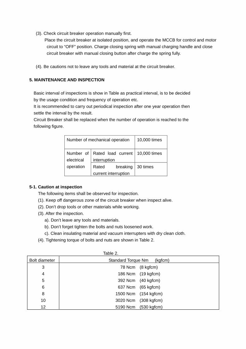
(4). Tightening torque of bolts and nuts are shown in Table 2.
Table 2.
Bolt diameter Standard Torque Nm (kgfcm)
3
4
5
6
8
10
12
78 Ncm (8 kgfcm)
186 Ncm (19 kgfcm)
392 Ncm (40 kgfcm)
637 Ncm (65 kgfcm)
1500 Ncm (154 kgfcm)
3020 Ncm (308 kgfcm)
5190 Ncm (530 kgfcm)
5-2. Patrol inspection
It is recommended to inspect the alive circuit breaker visually keeping off dangerous zone on
each patrol.
If any abnormality is found, stop operation immediately and investigate the circuit breaker.
No. Item Contents Remarks
1 General Condensation, ingress of dust, rain.
Abnormal sound, smell, color.
2 ON-OFF indicator Normal or not
3 Charge-Discharge
indication
Normal or not
4 Operation counter
Check No. of operation. Replace circuit breaker, if
the No. is 10000 or more.
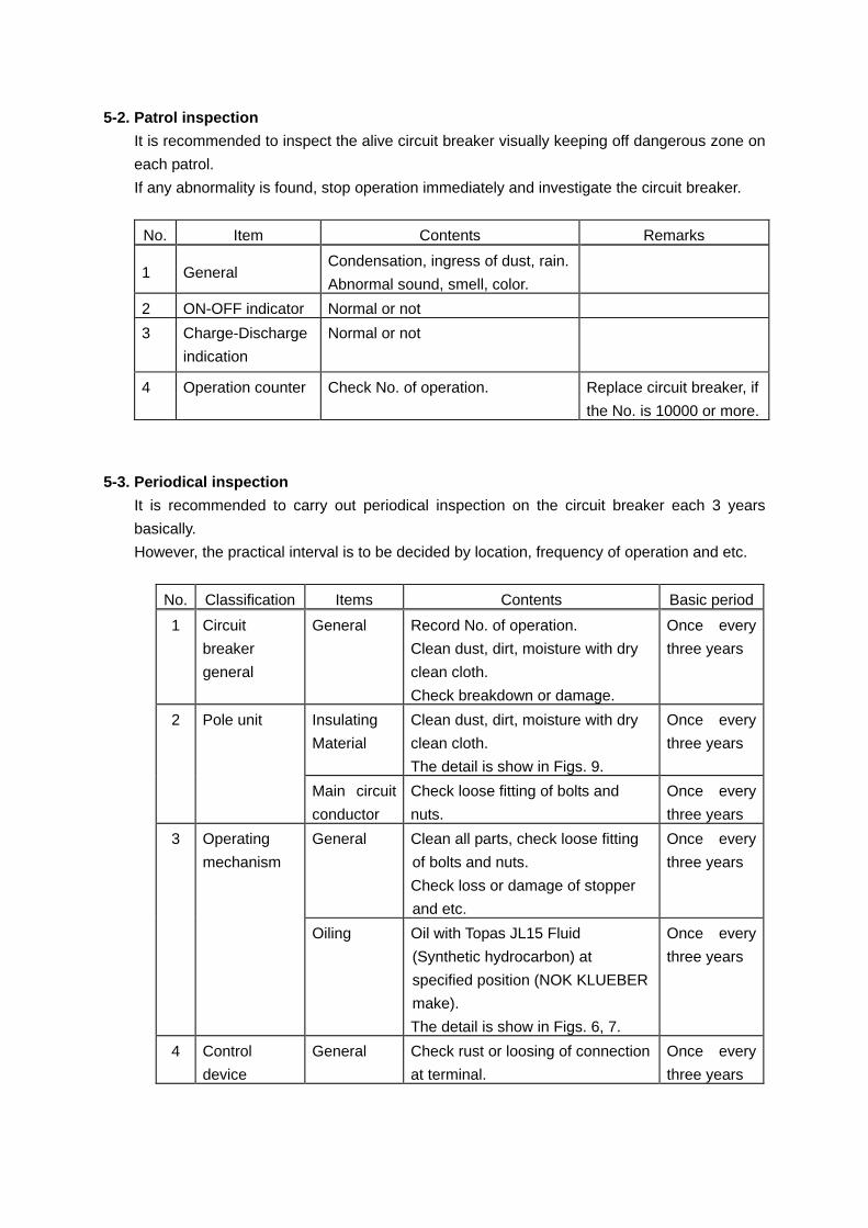
5-3. Periodical inspection
It is recommended to carry out periodical inspection on the circuit breaker each 3 years
basically.
However, the practical interval is to be decided by location, frequency of operation and etc.
No. Classification Items Contents Basic period
1 Circuit
breaker
general
General Record No. of operation.
Clean dust, dirt, moisture with dry
clean cloth.
Check breakdown or damage.
Once every
three years
2 Pole unit Insulating
Material
Clean dust, dirt, moisture with dry
clean cloth.
The detail is show in Figs. 9.
Once every
three years
Main circuit
conductor
Check loose fitting of bolts and
nuts.
Once every
three years
3 Operating
mechanism
General Clean all parts, check loose fitting
of bolts and nuts.
Check loss or damage of stopper
and etc.
Once every
three years
Oiling Oil with Topas JL15 Fluid
(Synthetic hydrocarbon) at
specified position (NOK KLUEBER
make).
The detail is show in Figs. 6, 7.
Once every
three years
4 Control
device
General Check rust or loosing of connection
at terminal.
Once every
three years
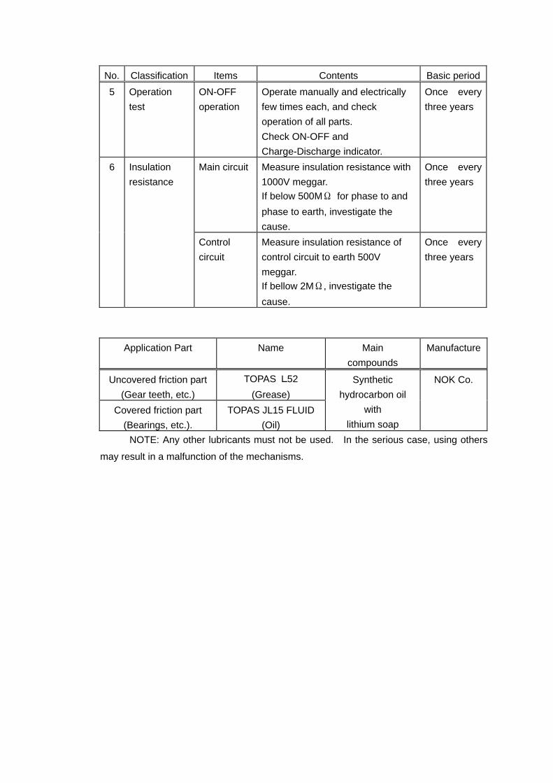
No. Classification Items Contents Basic period
5 Operation
test
ON-OFF
operation
Operate manually and electrically
few times each, and check
operation of all parts.
Check ON-OFF and
Charge-Discharge indicator.
Once every
three years
6 Insulation
resistance
Main circuit Measure insulation resistance with
1000V meggar.
If below 500MΩ for phase to and
phase to earth, investigate the
cause.
Once every
three years
Control
circuit
Measure insulation resistance of
control circuit to earth 500V
meggar. If bellow 2MΩ, investigate the
cause.
Once every
three years
Application Part Name Main
compounds
Manufacture
Uncovered friction part
(Gear teeth, etc.)
TOPAS L52
(Grease)
Synthetic
hydrocarbon oil
with
lithium soap
NOK Co.
Covered friction part
(Bearings, etc.).
TOPAS JL15 FLUID
(Oil)
NOTE: Any other lubricants must not be used. In the serious case, using others
may result in a malfunction of the mechanisms.
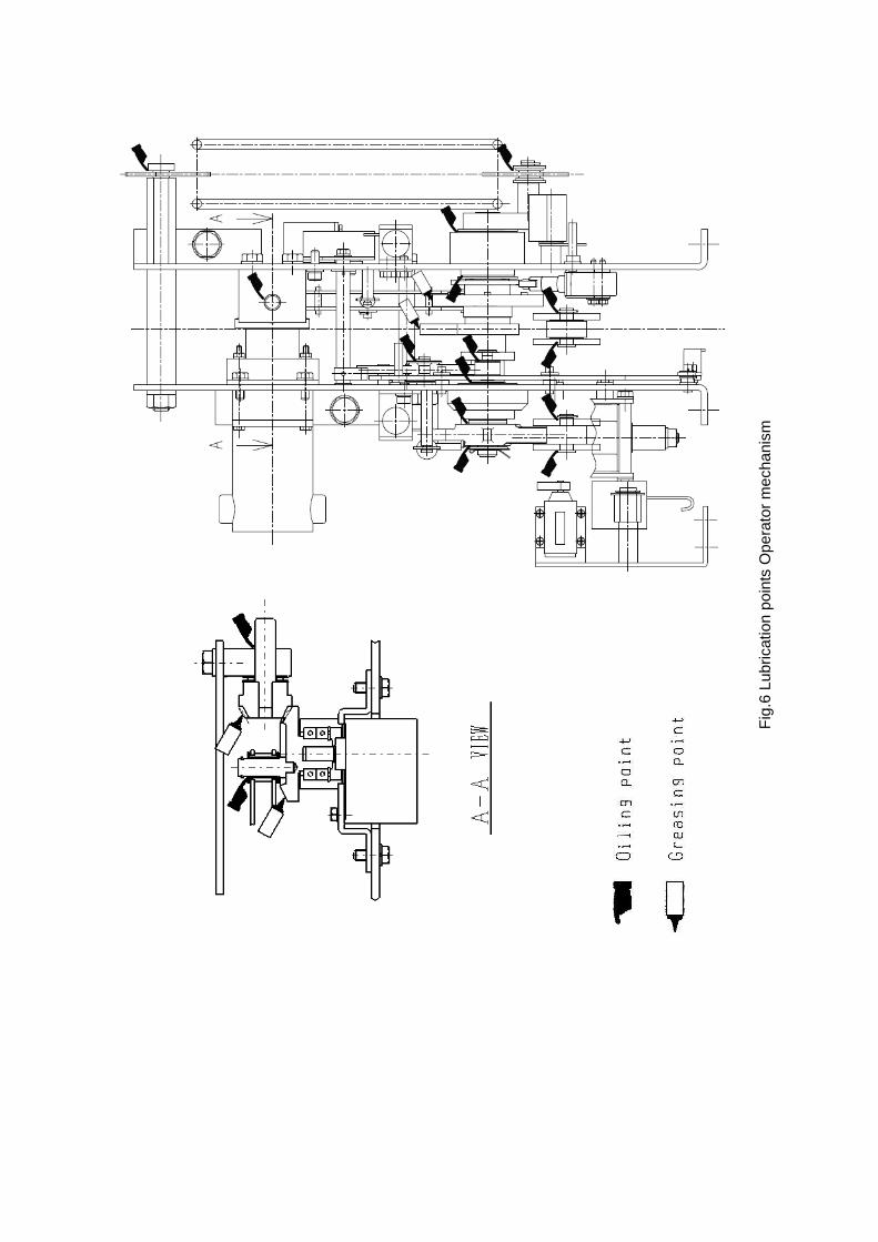
Fig
.6 L
ubric
atio
n po
ints
Ope
rato
r m
echa
nism
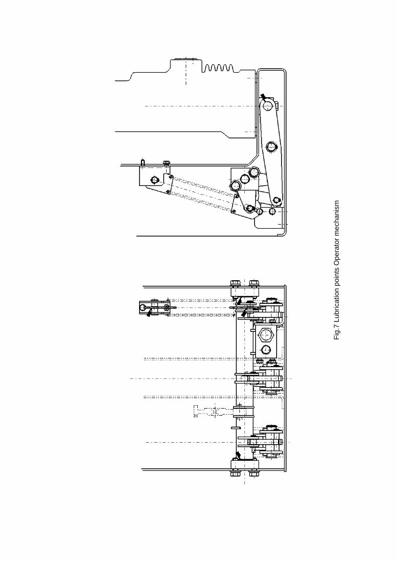
Fig
.7 L
ubric
atio
n po
ints
Ope
rato
r m
echa
nism
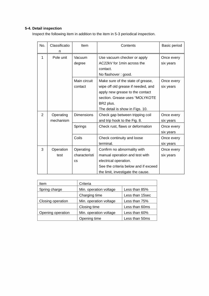
5-4. Detail inspection
Inspect the following item in addition to the item in 5-3 periodical inspection.
No. Classificatio
n
Item Contents Basic period
1 Pole unit
Vacuum
degree
Use vacuum checker or apply
AC22kV for 1min across the
contact.
No flashover : good.
Once every
six years
Main circuit
contact
Make sure of the state of grease,
wipe off old grease if needed, and
apply new grease to the contact
section. Grease uses “MOLYKOTE
BR2 plus.
The detail is show in Figs. 10.
Once every
six years
2 Operating
mechanism
Dimensions Check gap between tripping coil
and trip hook to the Fig. 8.
Once every
six years
Springs Check rust, flaws or deformation Once every
six years
Coils Check continuity and loose
terminal.
Once every
six years
3 Operation
test
Operating
characteristi
cs
Confirm no abnormality with
manual operation and test with
electrical operation.
See the criteria below and if exceed
the limit, investigate the cause.
Once every
six years
Item Criteria
Spring charge Min. operation voltage Less than 85%
Charging time Less than 15sec
Closing operation Min. operation voltage Less than 75%
Closing time Less than 60ms
Opening operation Min. operation voltage Less than 60%
Opening time Less than 50ms
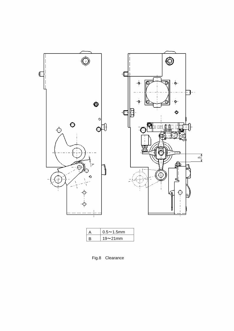
A 0.5~1.5mm
B 19~21mm
Fig.8 Clearance
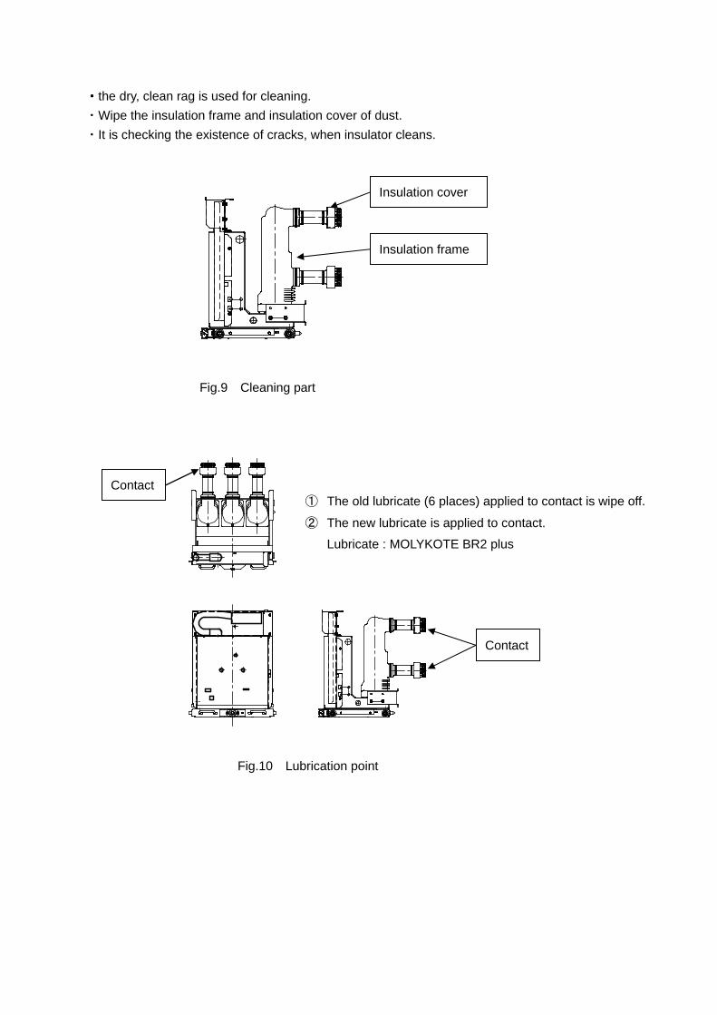
・・・・the dry, clean rag is used for cleaning.
・Wipe the insulation frame and insulation cover of dust.
・It is checking the existence of cracks, when insulator cleans.
Fig.9 Cleaning part
Fig.10 Lubrication point
Contact
Contact
① The old lubricate (6 places) applied to contact is wipe off.
② The new lubricate is applied to contact.
Lubricate : MOLYKOTE BR2 plus
Insulation frame
Insulation cover
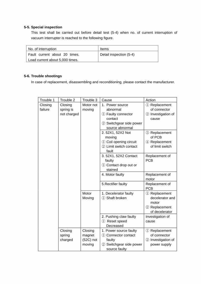
5-5. Special inspection
This test shall be carried out before detail test (5-4) when no. of current interruption of
vacuum interrupter is reached to the following figure.
No. of interruption Items
Fault current about 20 times.
Load current about 5,000 times.
Detail inspection (5-4)
5-6. Trouble shootings
In case of replacement, disassembling and reconditioning, please contact the manufacturer.
Trouble 1 Trouble 2 Trouble 3 Cause Action Closing failure
Closing spring is not charged
Motor not moving
1. Power source abnormal
① Faulty connector contact
② Switchgear side power source abnormal
① Replacement of connector
② Investigation of cause
2. 52X1, 52X2 Not moving
① Coil opening circuit ② Limit switch contact
fault
③ Replacement of PCB
④ Replacement of limit switch
3. 52X1, 52X2 Contact faulty
① Contact drop out or stained
Replacement of PCB
4. Motor faulty Replacement of motor
5.Rectifier faulty Replacement of PCB
Motor Moving
1. Decelerator faulty ① Shaft broken
① Replacement decelerator and motor
② Replacement of decelerator
2. Pushing claw faulty ① Reset speed
Decreased
Investigation of cause
Closing spring charged
Closing magnet (52C) not moving
1. Power source faulty ① Connector contact
faulty ② Switchgear side power
source faulty
① Replacement of connector
② Investigation of power supply
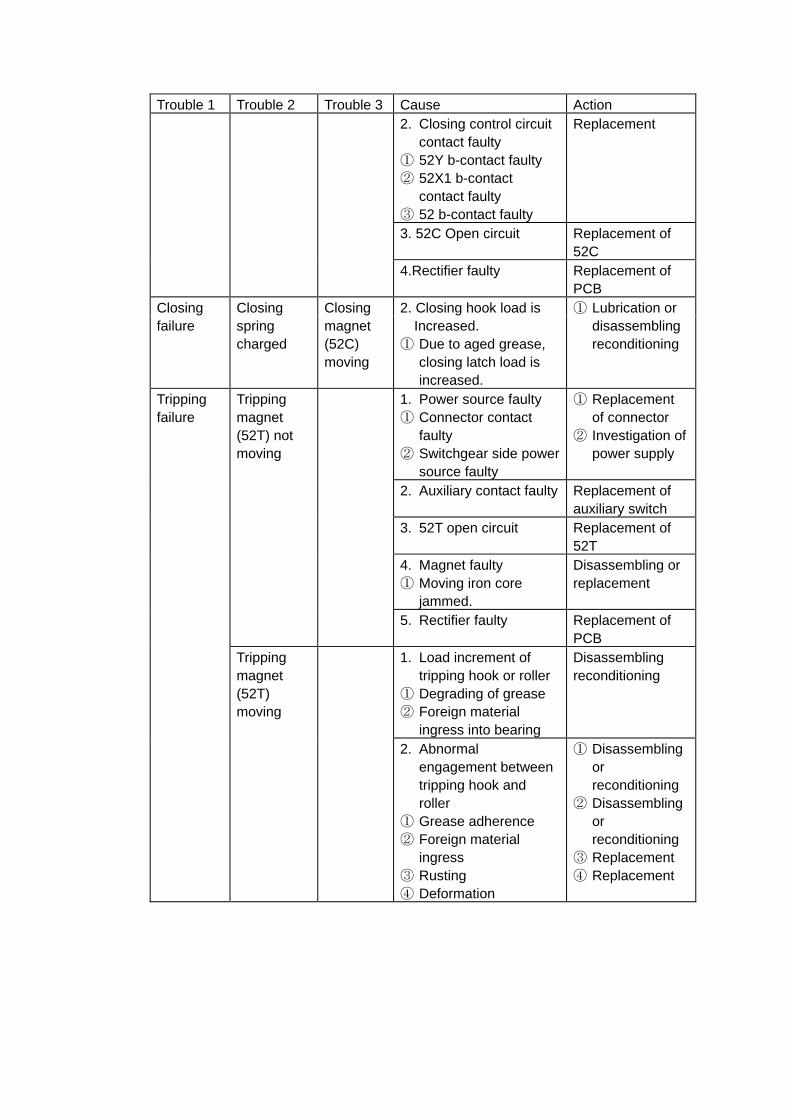
Trouble 1 Trouble 2 Trouble 3 Cause Action 2. Closing control circuit
contact faulty ① 52Y b-contact faulty ② 52X1 b-contact
contact faulty ③ 52 b-contact faulty
Replacement
3. 52C Open circuit Replacement of 52C
4.Rectifier faulty Replacement of PCB
Closing failure
Closing spring charged
Closing magnet (52C) moving
2. Closing hook load is Increased. ① Due to aged grease,
closing latch load is increased.
① Lubrication or disassembling reconditioning
Tripping failure
Tripping magnet (52T) not moving
1. Power source faulty ① Connector contact
faulty ② Switchgear side power
source faulty
① Replacement of connector
② Investigation of power supply
2. Auxiliary contact faulty Replacement of auxiliary switch
3. 52T open circuit Replacement of 52T
4. Magnet faulty ① Moving iron core
jammed.
Disassembling or replacement
5. Rectifier faulty Replacement of PCB
Tripping magnet (52T) moving
1. Load increment of tripping hook or roller
① Degrading of grease ② Foreign material
ingress into bearing
Disassembling reconditioning
2. Abnormal engagement between tripping hook and roller
① Grease adherence ② Foreign material
ingress ③ Rusting ④ Deformation
① Disassembling or reconditioning
② Disassembling or reconditioning
③ Replacement ④ Replacement

![INDEX [ ] · PDF fileArthit Platform Offshore Songkhla Year 2009-2012 Scope of work Preventive Maintenance MV & LV Switchgear • MV Vacuum circuit breaker • MV Vacuum contactor](https://img.pdfslide.tips/doc/110x75/5a7041e57f8b9abb538bc8db/index-wwwpmscothwwwpmscothprofileprofile16-3-58pdfpdf.jpg)