Embed Size (px)
Citation preview

Unofficial English translation offered by EuropElectro, for reference only
1
ICS
National Standard of the People's Republic of China
GB/T XXXXX—XXXX
电动汽车非车载传导式充电机与电池管理
系统通信协议
Electric Vehicle Communication Protocol Between Off-board Conductive
Charger and Battery Management System
(Working Draft)
Issued on XXXX - XX - XX Implemented on XXXX - XX - XX
Jointly Issued by General Administration of Quality Supervision, Inspection and Quarantine of
the People’s Republic of China; Standardization Administration of the People’s Rupublic of China
Unofficial English translation offered by EuropElectro, for reference only
2
Contents
Foreword ........................................................................................................................................... 3
1 Scope......................................................................................................................................... 4
2 Normative references .............................................................................................................. 4
3 Definitions ................................................................................................................................ 4
4 General requirements ............................................................................................................. 6
5 Network topology structure ................................................................................................... 6
6 Physical layer ........................................................................................................................... 6
7 Data link layer ......................................................................................................................... 6
7.1 General overview ......................................................................................................... 6
7.2 Frame format ............................................................................................................... 6
7.3 Protocol data unit (PDU) ............................................................................................ 7
7.4 Protocol data unit(PDU) format ................................................................................ 7
7.5 Parameter group number(PGN) ................................................................................ 7
7.6 Transmission protocol function .................................................................................. 8
7.7 Address allocation ....................................................................................................... 8
7.8 Message category ......................................................................................................... 8
8 Application layer ..................................................................................................................... 8
9 Charge message specifications between charger and BMS ................................................. 9
9.1 Overall charge process ...................................................................................................... 9
9.2 Charge process communication message category ......................................................... 9
9.3 messages between the charger and BMS ....................................................................... 13
Annex A (Informative) .................................................................................................................. 25
Annex B (Informative) .................................................................................................................. 30
Unofficial English translation offered by EuropElectro, for reference only
3
Foreword
This standard is drafted in accordance with the rules defined by GB/T 1.1.
This standard is proposed by XXXX.
This standard is centrally managed by XXXX.
The Standard Development Organizations include: XXXX.
The main developers include: XXXX
Unofficial English translation offered by EuropElectro, for reference only
4
Electric vehicle communication protocol
between off-board conductive charger and battery management system
1 Scope
This technical specification specifies the electric vehicle communication protocol between
off-board conductive charger (hereafter briefed as charger) and Battery Management System, as
BMS).
This specification applies to the electric vehicle off-board charger charged in the conductive
manner. Data transmission in the specification shall be in the format of lower-bit-first-sending.
Plus current value means discharge;Minus current value means charge.
2 Normative references
The following referenced documents are indispensable for the application of this document. For
dated references, only the edition cited applies. For undated references, the latest edition of the
referenced document (including any amendments) applies.
GB/T 19596-2004 Electric vehicle terminology
SAE J1939-11:1999 Physical Layer, 250K bits/s, Twisted Shielded Pair
SAE J1939-21:2001 Data link layer
SAE J1939-71:2002 Vehicle application layer
SAE J1939-73:2006 Application layer-diagnostics
ISO 11898-1:2003 Road vehicle-control area network (CAN) part1:Data link layer and
physical signaling)
ISO 11898-2:2003 Road vehicle-control area network (CAN) part2: High-speed medium
access unit)
ISO 15765-3:2004 Road vehicle-Diagnostics on control area network (CAN)
part3:Implementation of unified diagnostic services)
3 Definitions
For the purposes of this document, the terms and definitions covered in SAE J1939, ISO 11898,
GB/T 19596, and the following terms and definitions apply.
3.1
Frame
A series of data bits making up a complete message.
3.2
CAN data frame
The ordered bit fields necessary to create a CAN frame used to convey data, beginning with an
SOF and ending with an EOF.
3.3
Message
A “message” is equivalent to one or more “CAN Data Frames” that have the same Parameter
Group Number.
3.4
Identifier
The identifier portion of the CAN arbitration area.
Unofficial English translation offered by EuropElectro, for reference only
5
3.5
Standard frame
A CAN data frame using an 11 bit identifier as defined in “CAN bus 2.0B version”.
3.6
Extended frame
A CAN data frame using a 29 bit identifier as defined in “CAN bus 2.0B version”.
3.7
Priority
A 3-Bit area in an identifier that establishes the arbitration priority of the information
communicated. The highest priority is zero and the lowest priority is seven.
3.8
Parameter group (PG)
A collection of parameters that are conveyed in a message. Parameter Group includes
commands, data, requests, acknowledgments, and negative-acknowledgements.
3.9
Parameter group number (PGN)
A 24-Bit value used for uniquely identifying a parameter group. Parameter group number
encompass: reservation page, data page, PDU format field (8 bits), group extended field (8
bits).
3.10
Suspect parameter number (SPN)
A 19-bit value to be allocated to each parameter by application layer by parameter description
signal.
3.11
Protocol data unit (PDU)
A specific CAN data frame format.
3.12
Transport protocol
A part of data link layer which act as a kind of data transmission mechanism offered for≥9
bytes PGN.
3.13
Cell
The minimal unit of battery, normally comprising anode, cathode and electrolyte, whose rated
voltage equals the rated voltage of electrochemistry dipole.
3.14
Battery module
A combination of a group of connected cells.
3.15
Battery pack
A single mechanical combination of one or more battery module.
3.16
Diagnostic trouble code (DTC)
A 4-byte value that identifies the type of trouble, the associated failure mode and its
Unofficial English translation offered by EuropElectro, for reference only
6
occurrence count.
4 General requirements
4.1 The CAN (Control area network) communication protocol shall be adopted as the communic-
-ation system in this specification between charger and electric vehicle BMS for considering the
communication network compatibility between road vehicle control systems.
4.2 The Physical layer and data link layer of communication protocol shall be in conformity with
ISO 11898 and SAE J1939. Data frame format shall be in conformity with “CAN Bus 2.0B
version” published in Sept. 1991.
4.3 During charging, electric Voltage, Current and temperature etc. shall be monitored by charger
and BMS. Meanwhile, the whole charging process shall be managed by charging control
algorithm.
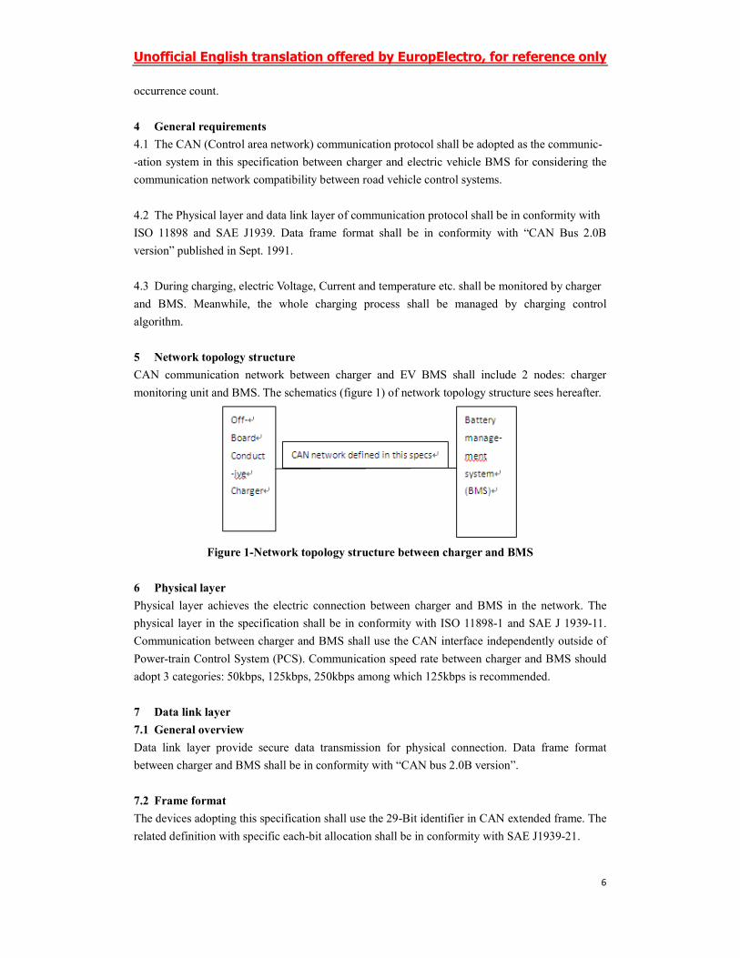
5 Network topology structure
CAN communication network between charger and EV BMS shall include 2 nodes: charger
monitoring unit and BMS. The schematics (figure 1) of network topology structure sees hereafter.
Figure 1-Network topology structure between charger and BMS
6 Physical layer
Physical layer achieves the electric connection between charger and BMS in the network. The
physical layer in the specification shall be in conformity with ISO 11898-1 and SAE J 1939-11.
Communication between charger and BMS shall use the CAN interface independently outside of
Power-train Control System (PCS). Communication speed rate between charger and BMS should
adopt 3 categories: 50kbps, 125kbps, 250kbps among which 125kbps is recommended.
7 Data link layer
7.1 General overview
Data link layer provide secure data transmission for physical connection. Data frame format
between charger and BMS shall be in conformity with “CAN bus 2.0B version”.
7.2 Frame format
The devices adopting this specification shall use the 29-Bit identifier in CAN extended frame. The
related definition with specific each-bit allocation shall be in conformity with SAE J1939-21.
Unofficial English translation offered by EuropElectro, for reference only
7
7.3 Protocol data unit (PDU)
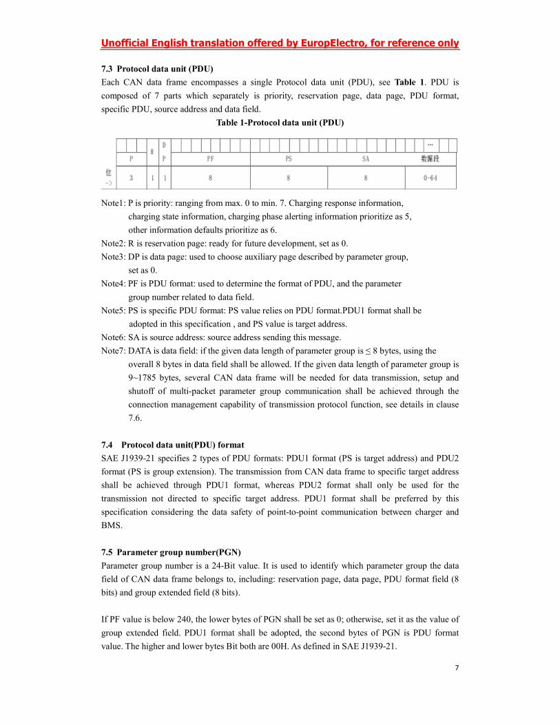
Each CAN data frame encompasses a single Protocol data unit (PDU), see Table 1. PDU is
composed of 7 parts which separately is priority, reservation page, data page, PDU format,
specific PDU, source address and data field.
Table 1-Protocol data unit (PDU)
Note1: P is priority: ranging from max. 0 to min. 7. Charging response information,
charging state information, charging phase alerting information prioritize as 5,
other information defaults prioritize as 6.
Note2: R is reservation page: ready for future development, set as 0.
Note3: DP is data page: used to choose auxiliary page described by parameter group,
set as 0.
Note4: PF is PDU format: used to determine the format of PDU, and the parameter
group number related to data field.
Note5: PS is specific PDU format: PS value relies on PDU format.PDU1 format shall be
adopted in this specification , and PS value is target address.
Note6: SA is source address: source address sending this message.
Note7: DATA is data field: if the given data length of parameter group is ≤ 8 bytes, using the
overall 8 bytes in data field shall be allowed. If the given data length of parameter group is
9~1785 bytes, several CAN data frame will be needed for data transmission, setup and
shutoff of multi-packet parameter group communication shall be achieved through the
connection management capability of transmission protocol function, see details in clause
7.6.
7.4 Protocol data unit(PDU) format
SAE J1939-21 specifies 2 types of PDU formats: PDU1 format (PS is target address) and PDU2
format (PS is group extension). The transmission from CAN data frame to specific target address
shall be achieved through PDU1 format, whereas PDU2 format shall only be used for the
transmission not directed to specific target address. PDU1 format shall be preferred by this
specification considering the data safety of point-to-point communication between charger and
BMS.
7.5 Parameter group number(PGN)
Parameter group number is a 24-Bit value. It is used to identify which parameter group the data
field of CAN data frame belongs to, including: reservation page, data page, PDU format field (8
bits) and group extended field (8 bits).
If PF value is below 240, the lower bytes of PGN shall be set as 0; otherwise, set it as the value of
group extended field. PDU1 format shall be adopted, the second bytes of PGN is PDU format
value. The higher and lower bytes Bit both are 00H. As defined in SAE J1939-21.
Unofficial English translation offered by EuropElectro, for reference only
8
7.6 Transmission protocol function
Transmission protocol is a kind of data transmission mechanism offered for≥9 Bytes PGN.
Transmission protocol function is divided in 2 major functions: message disassembly and
reorganization, connection management. The data using multi-packet data transmission
mechanism is the individual battery unit data sending from BMS to charger. Connection
initialization, data transmission and connection shutoff shall be in conformity with SAE J1939-21.
7.7 Address allocation
Network address is used to guarantee the uniqueness of message identifier and the source of
message. Charger and BMS addresses are defined as non-configurable addresses, which indicates
these addresses are fixed in the ECU program code. Also, any means including service tools can
not change its source address. Allocated addresses of charger and BMS are as followed as Table 2.
Table 2-Charger and BMS address allocation
Device First selected address
charger 229(E5H)
BMS 244(F4H)
7.8 Message category
“CAN bus 2.0B version” Covers 5 types of messages: command, request, broadcast/response,
confirm and group function. Commonly used in this specification are 2 types: request and confirm.
See details in SAE J1939-21.
8 Application layer
8.1 The definition of application layer mainly conforms to SAE J1939-71, in the form of
parameter and parameter group.
8.2 Parameter group shall be numbered adopting PGN, the content of data packet shall be
identified by different nodes according to PGN.
8.3 Using”request PGN” to proactively acquire the parameter group from other nodes, see details
in clause 7.8.
8.4 Sending data shall be achieved in the manner of periodic sending and event-driven.
8.5 If a single function is achieved through sending several PGN data, it is necessary to accept
several PGN message simultaneously in order to decide whether this function is successful or not.
8.6 When defining new parameter group, try to put parameters with the same function, parameters
with the same or similar refresh-frequency, parameters belonging to the same subsystem into the
same set of parameters. Meanwhile, new parameter group shall not only take advantage of the data
length of 8-bytes and put relevant parameters into the same group, but also consider scalability
and reserve part of bytes or Bits for future improvement.
Unofficial English translation offered by EuropElectro, for reference only
9
8.7 When revising the parameter group defined in this specification, it is not allowed to revise the
definition of the defined bytes or Bits; The newly added parameter shall be related with the
original parameter in the parameter group, it is not allowed to put non-relevant parameter into the
defined PGN just for saving the PGN number; It is allowed to use the defined original PGN for
ECU with similar functions, use undefined parts to increase identifier Bits for discerning the ECU
function, fully use the defined original parameter.
8.8 The definition of various trouble diagnostic shall be in conformity with the requirements of
CAN bus diagnostic system specified in ISO 15765-3 and SAE J1939-73.The defined
specification of trouble diagnostic message shall conform to SAE J1939-73 given in Annex B.
8.9 Sending message options during charging stage are divided into 2 categories: mandatory and
optional. Mandatory sending message shall be sent strictly according to message format and
content; while the content of optional sending message can be filled in with “FF”.
9 Charge message specifications between charger and BMS
9.1 Overall charge process
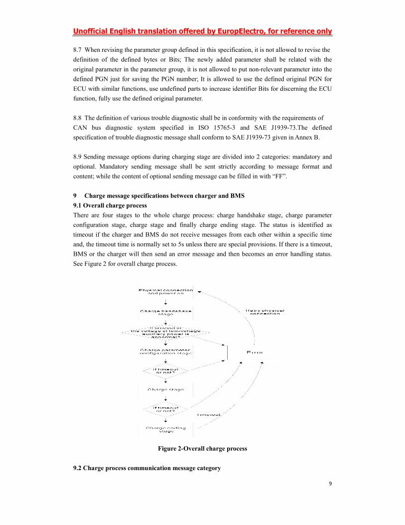
There are four stages to the whole charge process: charge handshake stage, charge parameter
configuration stage, charge stage and finally charge ending stage. The status is identified as
timeout if the charger and BMS do not receive messages from each other within a specific time
and, the timeout time is normally set to 5s unless there are special provisions. If there is a timeout,
BMS or the charger will then send an error message and then becomes an error handling status.
See Figure 2 for overall charge process.
Figure 2-Overall charge process
9.2 Charge process communication message category
Unofficial English translation offered by EuropElectro, for reference only
10
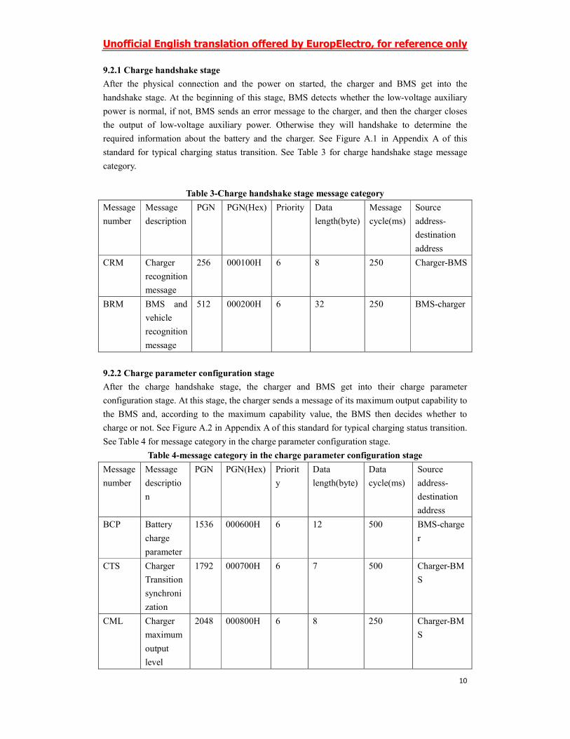
9.2.1 Charge handshake stage
After the physical connection and the power on started, the charger and BMS get into the
handshake stage. At the beginning of this stage, BMS detects whether the low-voltage auxiliary
power is normal, if not, BMS sends an error message to the charger, and then the charger closes
the output of low-voltage auxiliary power. Otherwise they will handshake to determine the
required information about the battery and the charger. See Figure A.1 in Appendix A of this
standard for typical charging status transition. See Table 3 for charge handshake stage message
category.
Table 3-Charge handshake stage message category
Message
number
Message
description
PGN PGN(Hex) Priority Data
length(byte)
Message
cycle(ms)
Source
address-
destination
address
CRM Charger
recognition
message
256 000100H 6 8 250 Charger-BMS
BRM BMS and
vehicle
recognition
message
512 000200H 6 32 250 BMS-charger
9.2.2 Charge parameter configuration stage
After the charge handshake stage, the charger and BMS get into their charge parameter
configuration stage. At this stage, the charger sends a message of its maximum output capability to
the BMS and, according to the maximum capability value, the BMS then decides whether to
charge or not. See Figure A.2 in Appendix A of this standard for typical charging status transition.
See Table 4 for message category in the charge parameter configuration stage.
Table 4-message category in the charge parameter configuration stage
Message
number
Message
descriptio
n
PGN PGN(Hex) Priorit
y
Data
length(byte)
Data
cycle(ms)
Source
address-
destination
address
BCP Battery
charge
parameter
1536 000600H 6 12 500 BMS-charge
r
CTS Charger
Transition
synchroni
zation
1792 000700H 6 7 500 Charger-BM
S
CML Charger
maximum
output
level
2048 000800H 6 8 250 Charger-BM
S
Unofficial English translation offered by EuropElectro, for reference only
11
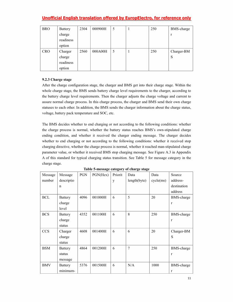
BRO Battery
charge
readiness
option
2304 000900H 5 1 250 BMS-charge
r
CRO Charger
charge
readiness
option
2560 000A00H 5 1 250 Charger-BM
S
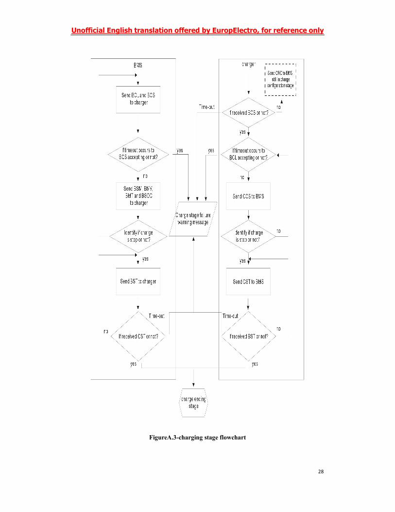
9.2.3 Charge stage
After the charge configuration stage, the charger and BMS get into their charge stage. Within the
whole charge stage, the BMS sends battery charge level requirements to the charger, according to
the battery charge level requirements. Then the charger adjusts the charge voltage and current to
assure normal charge process. In this charge process, the charger and BMS send their own charge
statuses to each other. In addition, the BMS sends the charger information about the charge status,
voltage, battery pack temperature and SOC, etc.
The BMS decides whether to end charging or not according to the following conditions: whether
the charge process is normal, whether the battery status reaches BMS’s own-stipulated charge
ending condition, and whether it received the charger ending message. The charger decides
whether to end charging or not according to the following conditions: whether it received stop
charging directive, whether the charge process is normal, whether it reached man-stipulated charge
parameter value, or whether it received BMS stop charging message. See Figure A.3 in Appendix
A of this standard for typical charging status transition. See Table 5 for message category in the
charge stage.
Table 5-message category of charge stage
Message
number
Message
descriptio
n
PGN PGN(Hex) Priorit
y
Data
length(byte)
Data
cycle(ms)
Source
address-
destination
address
BCL Battery
charge
level
4096 001000H 6 5 20 BMS-charge
r
BCS Battery
charge
status
4352 001100H 6 8 250 BMS-charge
r
CCS Charger
charge
status
4608 001400H 6 6 20 Charger-BM
S
BSM Battery
status
message
4864 001200H 6 7 250 BMS-charge
r
BMV Battery
minimum-
5376 001500H 6 N/A 1000 BMS-charge
r
Unofficial English translation offered by EuropElectro, for reference only
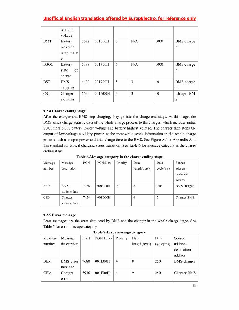
12
test-unit
voltage
BMT Battery
make-up
temperatur
e
5632 001600H 6 N/A 1000 BMS-charge
r
BSOC Battery
state of
charge
5888 001700H 6 N/A 1000 BMS-charge
r
BST BMS
stopping
6400 001900H 5 3 10 BMS-charge
r
CST Charger
stopping
6656 001A00H 5 3 10 Charger-BM
S
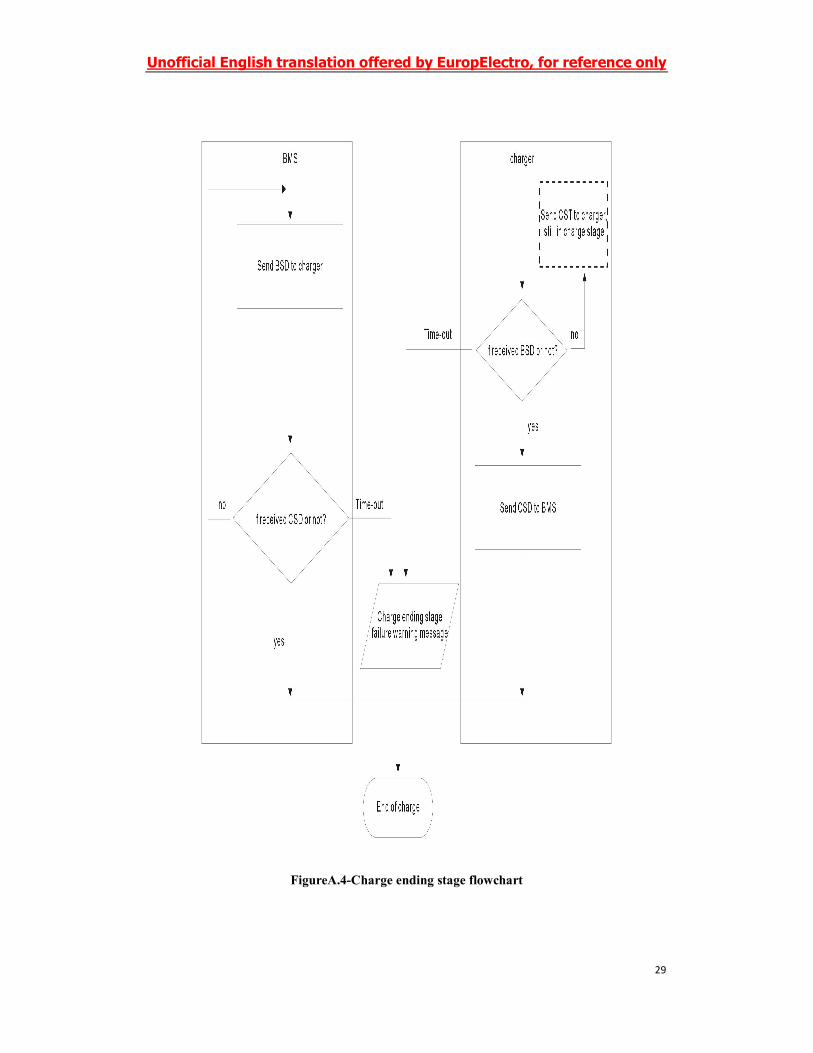
9.2.4 Charge ending stage
After the charger and BMS stop charging, they go into the charge end stage. At this stage, the
BMS sends charge statistic data of the whole charge process to the charger, which includes initial
SOC, final SOC, battery lowest voltage and battery highest voltage. The charger then stops the
output of low-voltage auxiliary power, at the meanwhile sends information in the whole charge
process such as output power and total charge time to the BMS. See Figure A.4 in Appendix A of
this standard for typical charging status transition. See Table 6 for message category in the charge
ending stage.
Table 6-Message category in the charge ending stage
Message
number
Message
description
PGN PGN(Hex) Priority Data
length(byte)
Data
cycle(ms)
Source
address-
destination
address
BSD BMS
statistic data
7168 001C00H 6 8 250 BMS-charger
CSD Charger
statistic data
7424 001D00H 6 7 Charger-BMS
9.2.5 Error message
Error messages are the error data send by BMS and the charger in the whole charge stage. See
Table 7 for error message category.
Table 7-Error message category
Message
number
Message
description
PGN PGN(Hex) Priority Data
length(byte)
Data
cycle(ms)
Source
address-
destination
address
BEM BMS error
message
7680 001E00H 4 8 250 BMS-charger
CEM Charger
error
7936 001F00H 4 9 250 Charger-BMS
Unofficial English translation offered by EuropElectro, for reference only
13
message
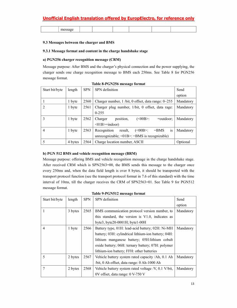
9.3 Messages between the charger and BMS
9.3.1 Message format and content in the charge handshake stage
a) PGN256 charger recognition message (CRM)
Message purpose: After BMS and the charger’s physical connection and the power supplying, the
charger sends one charge recognition message to BMS each 250ms. See Table 8 for PGN256
message format.
Table 8-PGN256 message format
Start bit/byte length SPN SPN definition Send
option
1 1 byte 2560 Charger number, 1 /bit, 0 offset, data range: 0~255 Mandatory
2 1 byte 2561 Charger plug number, 1/bit, 0 offset, data rage:
0-255
Mandatory
3 1 byte 2562 Charger position, (<00B>: =outdoor;
<01B>=indoor)
Mandatory
4 1 byte 2563 Recognition result, (<00B>: =BMS is
unrecognizable; <01B>: =BMS is recognizable)
Mandatory
5 4 bytes 2564 Charge location number, ASCII Optional
b) PGN 512 BMS and vehicle recognition message (BRM)
Message purpose: offering BMS and vehicle recognition message in the charge handshake stage.
After received CRM which is SPN2563=00, the BMS sends this message to the charger once
every 250ms and, when the data field length is over 8 bytes, it should be transported with the
transport protocol function (see the transport protocol format in 7.6 of this standard) with the time
interval of 10ms, till the charger receives the CRM of SPN2563=01. See Table 9 for PGN512
message format.
Table 9-PGN512 message format
Start bit/byte length SPN SPN definition Send
option
1 3 bytes 2565 BMS communication protocol version number, to
this standard, the version is V1.0, indicates as
byte3, byte20-0001H; byte1-00H
Mandatory
4 1 byte 2566 Battery type, 01H: lead-acid battery; 02H: Ni-MH
battery; 03H: cylindrical lithium-ion battery; 04H:
lithium manganese battery; 05H:lithium cobalt
oxide battery; 06H: ternary battery; 07H: polymer
lithium-ion battery; FFH: other batteries
Mandatory
5 2 bytes 2567 Vehicle battery system rated capacity /Ah, 0.1 Ah
/bit, 0 Ah offset, data range: 0 Ah-1000 Ah
Mandatory
7 2 bytes 2568 Vehicle battery system rated voltage /V, 0.1 V/bit,
0V offset, data range: 0 V-750 V
Mandatory
Unofficial English translation offered by EuropElectro, for reference only
14
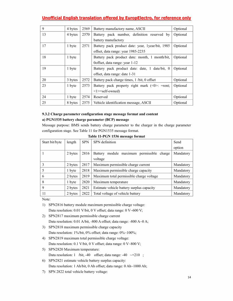
9 4 bytes 2569 Battery manufactory name, ASCII Optional
13 4 bytes 2570 Battery pack number, definition reserved by
battery manufactory
Optional
17 1 byte 2571 Battery pack product date: year, 1year/bit, 1985
offset, data range: year 1985-2235
Optional
18 1 byte Battery pack product date: month, 1 month/bit,
0offset, data range: year 1-12
Optional
19 1 byte Battery pack product date: date, 1 date/bit, 0
offset, data range: date 1-31
Optional
20 3 bytes 2572 Battery pack charge times, 1 /bit, 0 offset Optional
23 1 byte 2573 Battery pack property right mark (<0>: =rent;
<1>=self-owned)
Optional
24 1 byte 2574 Reserved Optional
25 8 bytes 2575 Vehicle identification message, ASCII Optional
9.3.2 Charge parameter configuration stage message format and content
a) PGN1535 battery charge parameter (BCP) message
Message purpose: BMS sends battery charge parameter to the charger in the charge parameter
configuration stage. See Table 11 for PGN1535 message format.
Table 11-PGN 1536 message format
Start bit/byte length SPN SPN definition Send
option
1 2 bytes 2816 Battery module maximum permissible charge
voltage
Mandatory
3 2 bytes 2817 Maximum permissible charge current Mandatory
5 1 byte 2818 Maximum permissible charge capacity Mandatory
6 2 bytes 2819 Maximum total permissible charge voltage Mandatory
8 1 byte 2820 Maximum temperature Mandatory
9 2 bytes 2821 Estimate vehicle battery surplus capacity Mandatory
11 2 bytes 2822 Total voltage of vehicle battery Mandatory
Note:
1) SPN2816 battery module maximum permissible charge voltage:
Data resolution: 0.01 V/bit, 0 V offset; data range: 0 V~600 V;
2) SPN2817 maximum permissible charge current
Data resolution: 0.01 A/bit, -800 A offset; data range: -800 A~0 A;
3) SPN2818 maximum permissible charge capacity
Data resolution: 1%/bit, 0% offset; data range: 0%~100%;
4) SPN2819 maximum total permissible charge voltage:
Data resolution: 0.1 V/bit, 0 V offset; data range: 0 V~800 V;
5) SPN2820 Maximum temperature:
Data resolution: 1 ℃/bit, -40 ℃ offset; data range: -40 ℃~+210 ℃;
6) SPN2821 estimate vehicle battery surplus capacity:
Data resolution: 1 Ah/bit, 0 Ah offset; data range: 0 Ah~1000 Ah;
7) SPN 2822 total vehicle battery voltage:
Unofficial English translation offered by EuropElectro, for reference only
15
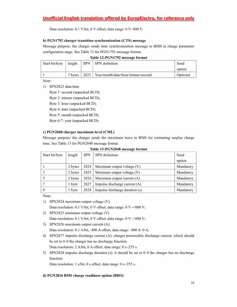
Data resolution: 0.1 V/bit, 0 V offset; data range: 0 V~800 V.
b) PGN1792 charger transition synchronization (CTS) message
Message purpose: the charger sends time synchronization message to BMS in charge parameter
configuration stage. See Table 12 for PGN1792 message format.
Table 12-PGN1792 message format
Start bit/byte length SPN SPN definition Send
option
1 7 bytes 2823 Year/month/date/hour/minute/second Optional
Note:
1) SPN2823 date/time
Byte 1: second (unpacked BCD);
Byte 2: minute (unpacked BCD);
Byte 3: hour (unpacked BCD);
Byte 4: date (unpacked BCD);
Byte 5: month (unpacked BCD);
Byte 6-7: year (unpacked BCD).
c) PGN2048 charger maximum level (CML)
Message purpose: the charger sends the maximum leave to BMS for estimating surplus charge
time. See Table 13 for PGN2048 message format.
Table 13-PGN2048 message format
Start bit/byte length SPN SPN definition Send
option
1 2 bytes 2824 Maximum output voltage (V) Mandatory
3 2 bytes 2825 Minimum output voltage (V) Mandatory
5 2 bytes 2826 Maximum output current (A) Mandatory
7 1 byte 2827 Impulse discharge current (A) Mandatory
8 1 byte 2828 Impulse discharge duration (s) Mandatory
Note:
1) SPN2824 maximum output voltage (V)
Data resolution: 0.1 V/bit, 0 V offset; data range: 0 V~+800 V;
2) SPN2825 minimum output voltage (V)
Data resolution: 0.1 V/bit, 0 V offset; data range: 0 V~+800 V;
3) SPN2826 maximum output current (A):
Data resolution: 0.1 A/bit, -800 A offset; data range: -800 A~0 A;
4) SPN2877 impulse discharge current (A): charger permissible discharge current, which should
be set to 0 if the charger has no discharge function.
Data resolution: 2 A/bit, 0 A offset; data range: 0 s~255 s.
5) SPN2828 impulse discharge duration (s): it should be set to 0 if the charger has no discharge
function.
Data resolution: 1 s/bit, 0 s offset; data range: 0 s~255 s.
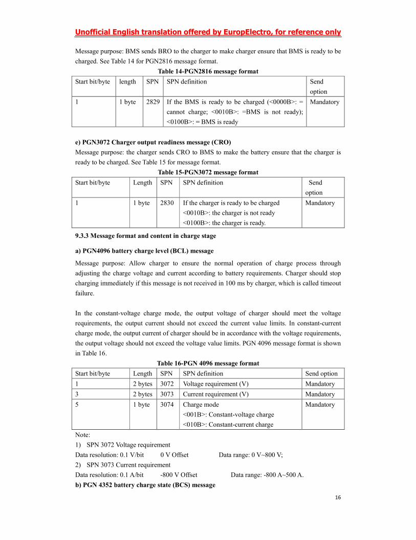
d) PGN2816 BMS charge readiness option (BRO)
Unofficial English translation offered by EuropElectro, for reference only
16
Message purpose: BMS sends BRO to the charger to make charger ensure that BMS is ready to be
charged. See Table 14 for PGN2816 message format.
Table 14-PGN2816 message format
Start bit/byte length SPN SPN definition Send
option
1 1 byte 2829 If the BMS is ready to be charged (<0000B>: =
cannot charge; <0010B>: =BMS is not ready);
<0100B>: = BMS is ready
Mandatory
e) PGN3072 Charger output readiness message (CRO)
Message purpose: the charger sends CRO to BMS to make the battery ensure that the charger is
ready to be charged. See Table 15 for message format.
Table 15-PGN3072 message format
Start bit/byte Length SPN SPN definition Send
option
1 1 byte 2830 If the charger is ready to be charged
<0010B>: the charger is not ready
<0100B>: the charger is ready.
Mandatory
9.3.3 Message format and content in charge stage
a) PGN4096 battery charge level (BCL) message
Message purpose: Allow charger to ensure the normal operation of charge process through
adjusting the charge voltage and current according to battery requirements. Charger should stop
charging immediately if this message is not received in 100 ms by charger, which is called timeout
failure.
In the constant-voltage charge mode, the output voltage of charger should meet the voltage
requirements, the output current should not exceed the current value limits. In constant-current
charge mode, the output current of charger should be in accordance with the voltage requirements,
the output voltage should not exceed the voltage value limits. PGN 4096 message format is shown
in Table 16.
Table 16-PGN 4096 message format
Start bit/byte Length SPN SPN definition Send option
1 2 bytes 3072 Voltage requirement (V) Mandatory
3 2 bytes 3073 Current requirement (V) Mandatory
5 1 byte 3074 Charge mode
<001B>: Constant-voltage charge
<010B>: Constant-current charge
Mandatory
Note:
1) SPN 3072 Voltage requirement
Data resolution: 0.1 V/bit 0 V Offset Data range: 0 V~800 V;
2) SPN 3073 Current requirement
Data resolution: 0.1 A/bit -800 V Offset Data range: -800 A~500 A.
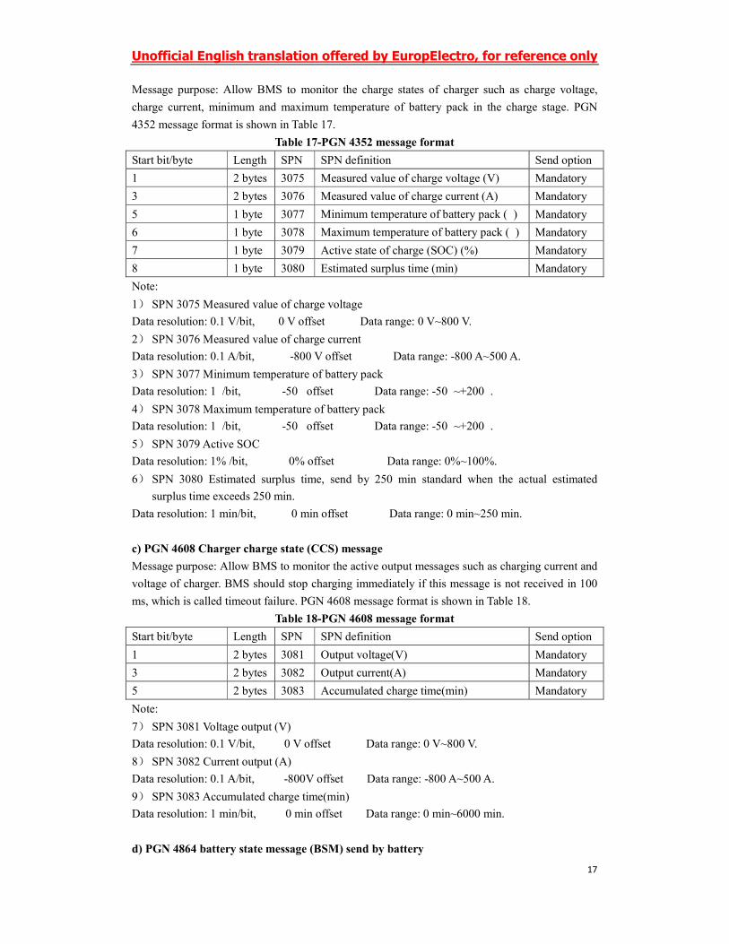
b) PGN 4352 battery charge state (BCS) message
Unofficial English translation offered by EuropElectro, for reference only
17
Message purpose: Allow BMS to monitor the charge states of charger such as charge voltage,
charge current, minimum and maximum temperature of battery pack in the charge stage. PGN
4352 message format is shown in Table 17.
Table 17-PGN 4352 message format
Start bit/byte Length SPN SPN definition Send option
1 2 bytes 3075 Measured value of charge voltage (V) Mandatory
3 2 bytes 3076 Measured value of charge current (A) Mandatory
5 1 byte 3077 Minimum temperature of battery pack (℃) Mandatory
6 1 byte 3078 Maximum temperature of battery pack (℃) Mandatory
7 1 byte 3079 Active state of charge (SOC) (%) Mandatory
8 1 byte 3080 Estimated surplus time (min) Mandatory
Note:
1) SPN 3075 Measured value of charge voltage
Data resolution: 0.1 V/bit, 0 V offset Data range: 0 V~800 V.
2) SPN 3076 Measured value of charge current
Data resolution: 0.1 A/bit, -800 V offset Data range: -800 A~500 A.
3) SPN 3077 Minimum temperature of battery pack
Data resolution: 1℃/bit, -50℃ offset Data range: -50℃~+200℃.
4) SPN 3078 Maximum temperature of battery pack
Data resolution: 1℃/bit, -50℃ offset Data range: -50℃~+200℃.
5) SPN 3079 Active SOC
Data resolution: 1% /bit, 0% offset Data range: 0%~100%.
6) SPN 3080 Estimated surplus time, send by 250 min standard when the actual estimated
surplus time exceeds 250 min.
Data resolution: 1 min/bit, 0 min offset Data range: 0 min~250 min.
c) PGN 4608 Charger charge state (CCS) message
Message purpose: Allow BMS to monitor the active output messages such as charging current and
voltage of charger. BMS should stop charging immediately if this message is not received in 100
ms, which is called timeout failure. PGN 4608 message format is shown in Table 18.
Table 18-PGN 4608 message format
Start bit/byte Length SPN SPN definition Send option
1 2 bytes 3081 Output voltage(V) Mandatory
3 2 bytes 3082 Output current(A) Mandatory
5 2 bytes 3083 Accumulated charge time(min) Mandatory
Note:
7) SPN 3081 Voltage output (V)
Data resolution: 0.1 V/bit, 0 V offset Data range: 0 V~800 V.
8) SPN 3082 Current output (A)
Data resolution: 0.1 A/bit, -800V offset Data range: -800 A~500 A.
9) SPN 3083 Accumulated charge time(min)
Data resolution: 1 min/bit, 0 min offset Data range: 0 min~6000 min.
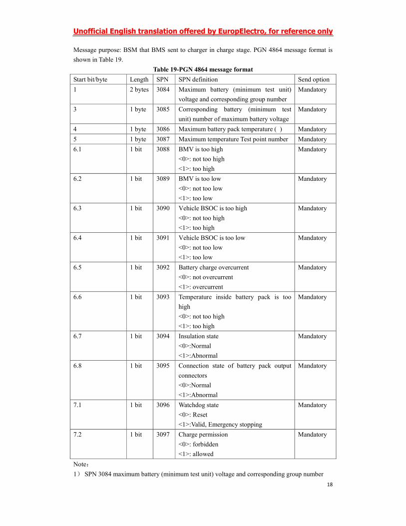
d) PGN 4864 battery state message (BSM) send by battery
Unofficial English translation offered by EuropElectro, for reference only
18
Message purpose: BSM that BMS sent to charger in charge stage. PGN 4864 message format is
shown in Table 19.
Table 19-PGN 4864 message format
Start bit/byte Length SPN SPN definition Send option
1 2 bytes 3084 Maximum battery (minimum test unit)
voltage and corresponding group number
Mandatory
3 1 byte 3085 Corresponding battery (minimum test
unit) number of maximum battery voltage
Mandatory
4 1 byte 3086 Maximum battery pack temperature (℃) Mandatory
5 1 byte 3087 Maximum temperature Test point number Mandatory
6.1 1 bit 3088 BMV is too high
<0>: not too high
<1>: too high
Mandatory
6.2 1 bit 3089 BMV is too low
<0>: not too low
<1>: too low
Mandatory
6.3 1 bit 3090 Vehicle BSOC is too high
<0>: not too high
<1>: too high
Mandatory
6.4 1 bit 3091 Vehicle BSOC is too low
<0>: not too low
<1>: too low
Mandatory
6.5 1 bit 3092 Battery charge overcurrent
<0>: not overcurrent
<1>: overcurrent
Mandatory
6.6 1 bit 3093 Temperature inside battery pack is too
high
<0>: not too high
<1>: too high
Mandatory
6.7 1 bit 3094 Insulation state
<0>:Normal
<1>:Abnormal
Mandatory
6.8 1 bit 3095 Connection state of battery pack output
connectors
<0>:Normal
<1>:Abnormal
Mandatory
7.1 1 bit 3096 Watchdog state
<0>: Reset
<1>:Valid, Emergency stopping
Mandatory
7.2 1 bit 3097 Charge permission
<0>: forbidden
<1>: allowed
Mandatory
Note:
1) SPN 3084 maximum battery (minimum test unit) voltage and corresponding group number
Unofficial English translation offered by EuropElectro, for reference only
19
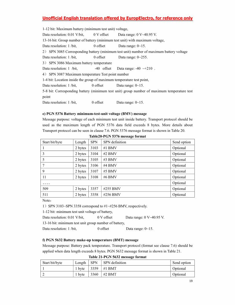
1-12 bit: Maximum battery (minimum test unit) voltage,
Data resolution: 0.01 V/bit, 0 V offset Data range: 0 V~40.95 V.
13-16 bit: Group number of battery (minimum test unit) with maximum voltage,
Data resolution: 1 /bit, 0 offset Data range: 0~15.
2) SPN 3085 Corresponding battery (minimum test unit) number of maximum battery voltage
Data resolution: 1 /bit, 0 offset Data range: 0~255.
3) SPN 3086 Maximum battery temperature
Data resolution: 1℃/bit, -40℃ offset Data range: -40℃~+210℃.
4) SPN 3087 Maximum temperature Test point number
1-4 bit: Location inside the group of maximum temperature test point,
Data resolution: 1 /bit, 0 offset Data range: 0~15.
5-8 bit: Corresponding battery (minimum test unit) group number of maximum temperature test
point
Data resolution: 1 /bit, 0 offset Data range: 0~15.
e) PGN 5376 Battery minimum-test-unit voltage (BMV) message
Message purpose: voltage of each minimum test unit inside battery. Transport protocol should be
used as the maximum length of PGN 5376 data field exceeds 8 bytes. More details about
Transport protocol can be seen in clause 7.6. PGN 5376 message format is shown in Table 20.
Table20-PGN 5376 message format
Start bit/byte Length SPN SPN definition Send option
1 2 bytes 3103 #1 BMV Optional
3 2 bytes 3104 #2 BMV Optional
5 2 bytes 3105 #3 BMV Optional
7 2 bytes 3106 #4 BMV Optional
9 2 bytes 3107 #5 BMV Optional
11 2 bytes 3108 #6 BMV Optional
。。。。 Optional
509 2 bytes 3357 #255 BMV Optional
511 2 bytes 3358 #256 BMV Optional
Note:
1)SPN 3103~SPN 3358 correspond to #1~#256 BMV, respectively.
1-12 bit: minimum test unit voltage of battery,
Data resolution: 0.01 V/bit, 0 V offset Data range: 0 V~40.95 V.
13-16 bit: minimum test unit group number of battery,
Data resolution: 1 /bit, 0 offset Data range: 0~15.
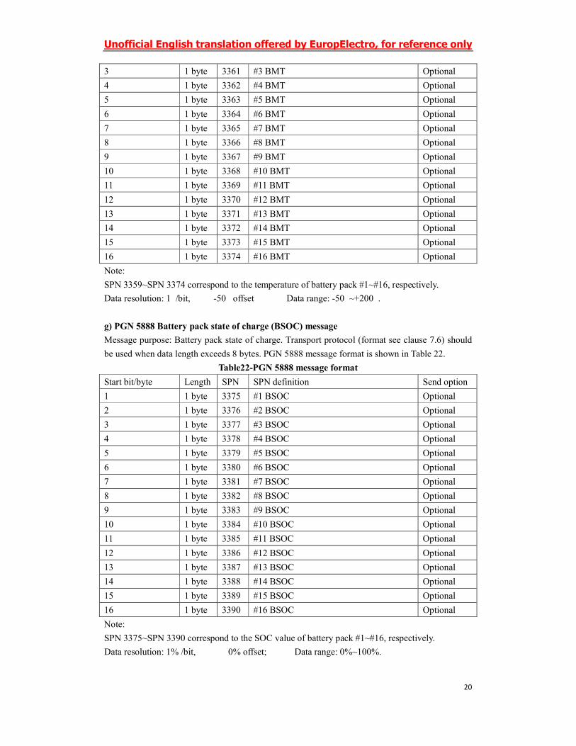
f) PGN 5632 Battery make-up temperature (BMT) message
Message purpose: Battery pack temperature. Transport protocol (format see clause 7.6) should be
applied when data length exceeds 8 bytes. PGN 5632 message format is shown in Table 21.
Table 21-PGN 5632 message format
Start bit/byte Length SPN SPN definition Send option
1 1 byte 3359 #1 BMT Optional
2 1 byte 3360 #2 BMT Optional
Unofficial English translation offered by EuropElectro, for reference only
20
3 1 byte 3361 #3 BMT Optional
4 1 byte 3362 #4 BMT Optional
5 1 byte 3363 #5 BMT Optional
6 1 byte 3364 #6 BMT Optional
7 1 byte 3365 #7 BMT Optional
8 1 byte 3366 #8 BMT Optional
9 1 byte 3367 #9 BMT Optional
10 1 byte 3368 #10 BMT Optional
11 1 byte 3369 #11 BMT Optional
12 1 byte 3370 #12 BMT Optional
13 1 byte 3371 #13 BMT Optional
14 1 byte 3372 #14 BMT Optional
15 1 byte 3373 #15 BMT Optional
16 1 byte 3374 #16 BMT Optional
Note:
SPN 3359~SPN 3374 correspond to the temperature of battery pack #1~#16, respectively.
Data resolution: 1℃/bit, -50℃ offset Data range: -50℃~+200℃.
g) PGN 5888 Battery pack state of charge (BSOC) message
Message purpose: Battery pack state of charge. Transport protocol (format see clause 7.6) should
be used when data length exceeds 8 bytes. PGN 5888 message format is shown in Table 22.
Table22-PGN 5888 message format
Start bit/byte Length SPN SPN definition Send option
1 1 byte 3375 #1 BSOC Optional
2 1 byte 3376 #2 BSOC Optional
3 1 byte 3377 #3 BSOC Optional
4 1 byte 3378 #4 BSOC Optional
5 1 byte 3379 #5 BSOC Optional
6 1 byte 3380 #6 BSOC Optional
7 1 byte 3381 #7 BSOC Optional
8 1 byte 3382 #8 BSOC Optional
9 1 byte 3383 #9 BSOC Optional
10 1 byte 3384 #10 BSOC Optional
11 1 byte 3385 #11 BSOC Optional
12 1 byte 3386 #12 BSOC Optional
13 1 byte 3387 #13 BSOC Optional
14 1 byte 3388 #14 BSOC Optional
15 1 byte 3389 #15 BSOC Optional
16 1 byte 3390 #16 BSOC Optional
Note:
SPN 3375~SPN 3390 correspond to the SOC value of battery pack #1~#16, respectively.
Data resolution: 1% /bit, 0% offset; Data range: 0%~100%.
Unofficial English translation offered by EuropElectro, for reference only
21
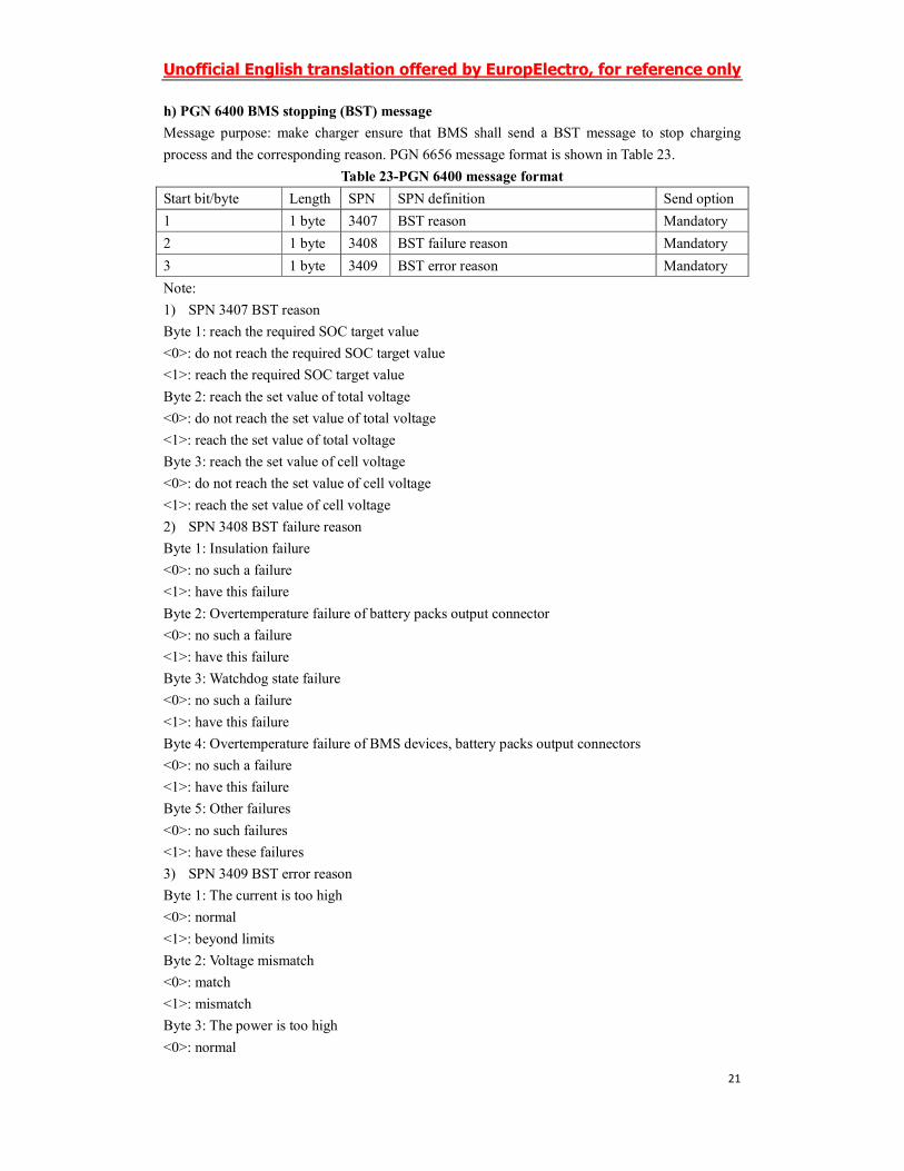
h) PGN 6400 BMS stopping (BST) message
Message purpose: make charger ensure that BMS shall send a BST message to stop charging
process and the corresponding reason. PGN 6656 message format is shown in Table 23.
Table 23-PGN 6400 message format
Start bit/byte Length SPN SPN definition Send option
1 1 byte 3407 BST reason Mandatory
2 1 byte 3408 BST failure reason Mandatory
3 1 byte 3409 BST error reason Mandatory
Note:
1) SPN 3407 BST reason
Byte 1: reach the required SOC target value
<0>: do not reach the required SOC target value
<1>: reach the required SOC target value
Byte 2: reach the set value of total voltage
<0>: do not reach the set value of total voltage
<1>: reach the set value of total voltage
Byte 3: reach the set value of cell voltage
<0>: do not reach the set value of cell voltage
<1>: reach the set value of cell voltage
2) SPN 3408 BST failure reason
Byte 1: Insulation failure
<0>: no such a failure
<1>: have this failure
Byte 2: Overtemperature failure of battery packs output connector
<0>: no such a failure
<1>: have this failure
Byte 3: Watchdog state failure
<0>: no such a failure
<1>: have this failure
Byte 4: Overtemperature failure of BMS devices, battery packs output connectors
<0>: no such a failure
<1>: have this failure
Byte 5: Other failures
<0>: no such failures
<1>: have these failures
3) SPN 3409 BST error reason
Byte 1: The current is too high
<0>: normal
<1>: beyond limits
Byte 2: Voltage mismatch
<0>: match
<1>: mismatch
Byte 3: The power is too high
<0>: normal

Unofficial English translation offered by EuropElectro, for reference only
22
<1>: beyond limits
i) PGN 6656 Charger stopping (CST) message
Message purpose: make BMS ensure that the charge process of charger shall be ended and the
corresponding reason. PGN 6656 message format is shown in Table 24.
Table 24-PGN 6656 message format
Start bit/byte Length SPN SPN definition Send option
1 1 byte 3410 CST reason Mandatory
2 1 byte 3411 CST failure reason Mandatory
3 1 byte 3412 CST error reason Mandatory
Note:
1) SPN3410 CST reason:
Byte 1: reach the value of SOC set by charger
<0>: not reach the value of SOC set by charger;
<1>: reach the value of SOC set by charger.
Byte 2: reach the electric values set by charger
<0>: do not reach the electric values set by charger
<1>: reach the electric values set by charger
2) SPN3411 CST failure reason
Byte 1: Charger overtemperature failure
<0>: no charger overtemperature failure
<1>: have a charger overtemperature failure
Byte 2: Overtemperature failure between connective devices inside the charge
<0>: no such a failure
<1>: have this failure
Byte 3: Cannot transport required electricity
<0>: no such a failure
<1>: have this failure
Byte 4: Manual-disturb stopping
<0>: no such a failure
<1>: have this failure
Byte 5: Other failures
<0>: no such failures
<1>: have these failures
3) SPN3412 CST error reason
Byte 1: Current mismatch
<0>: no such an error
<1>: have this error
Byte 2: Voltage mismatch
<0>: no such an error
<1>: have this error
Byte 3: reach the time set by charger
<0>: do not reach the time set by charger
<1>: reach the time set by charger
Byte 4: If the charger received the stop charging command send by power grid
Unofficial English translation offered by EuropElectro, for reference only
23
<0>: did not receive the stop charging command send by power grid
<1>: received the stop charging command send by power grid
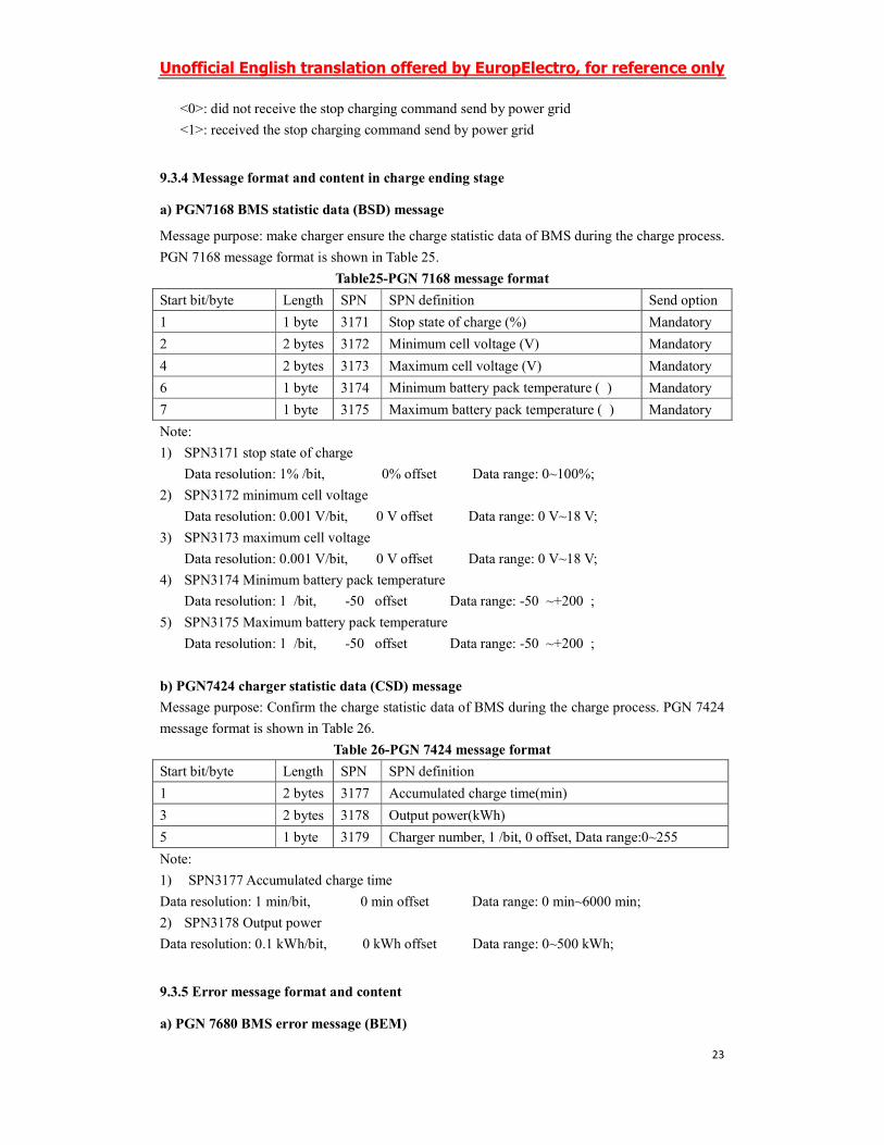
9.3.4 Message format and content in charge ending stage
a) PGN7168 BMS statistic data (BSD) message
Message purpose: make charger ensure the charge statistic data of BMS during the charge process.
PGN 7168 message format is shown in Table 25.
Table25-PGN 7168 message format
Start bit/byte Length SPN SPN definition Send option
1 1 byte 3171 Stop state of charge (%) Mandatory
2 2 bytes 3172 Minimum cell voltage (V) Mandatory
4 2 bytes 3173 Maximum cell voltage (V) Mandatory
6 1 byte 3174 Minimum battery pack temperature (℃) Mandatory
7 1 byte 3175 Maximum battery pack temperature (℃) Mandatory
Note:
1) SPN3171 stop state of charge
Data resolution: 1% /bit, 0% offset Data range: 0~100%;
2) SPN3172 minimum cell voltage
Data resolution: 0.001 V/bit, 0 V offset Data range: 0 V~18 V;
3) SPN3173 maximum cell voltage
Data resolution: 0.001 V/bit, 0 V offset Data range: 0 V~18 V;
4) SPN3174 Minimum battery pack temperature
Data resolution: 1℃/bit, -50℃ offset Data range: -50℃~+200℃;
5) SPN3175 Maximum battery pack temperature
Data resolution: 1℃/bit, -50℃ offset Data range: -50℃~+200℃;
b) PGN7424 charger statistic data (CSD) message
Message purpose: Confirm the charge statistic data of BMS during the charge process. PGN 7424
message format is shown in Table 26.
Table 26-PGN 7424 message format
Start bit/byte Length SPN SPN definition
1 2 bytes 3177 Accumulated charge time(min)
3 2 bytes 3178 Output power(kWh)
5 1 byte 3179 Charger number, 1 /bit, 0 offset, Data range:0~255
Note:
1) SPN3177 Accumulated charge time
Data resolution: 1 min/bit, 0 min offset Data range: 0 min~6000 min;
2) SPN3178 Output power
Data resolution: 0.1 kWh/bit, 0 kWh offset Data range: 0~500 kWh;
9.3.5 Error message format and content
a) PGN 7680 BMS error message (BEM)
Unofficial English translation offered by EuropElectro, for reference only
24
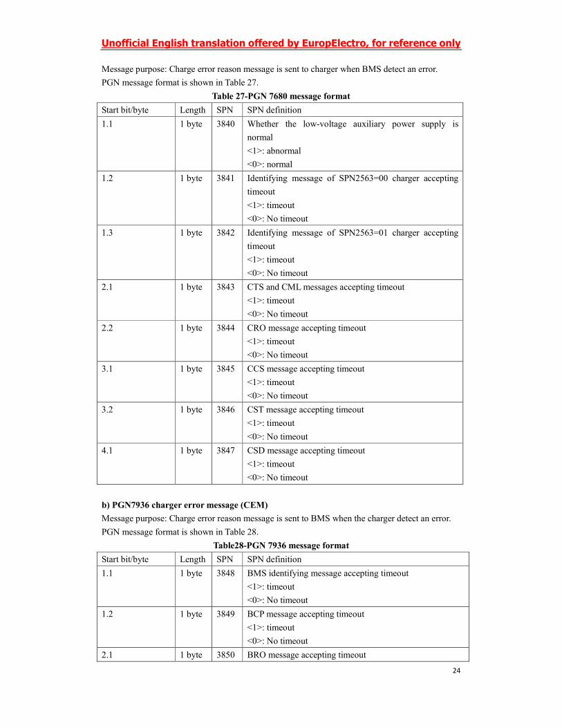
Message purpose: Charge error reason message is sent to charger when BMS detect an error.
PGN message format is shown in Table 27.
Table 27-PGN 7680 message format
Start bit/byte Length SPN SPN definition
1.1 1 byte 3840 Whether the low-voltage auxiliary power supply is
normal
<1>: abnormal
<0>: normal
1.2 1 byte 3841 Identifying message of SPN2563=00 charger accepting
timeout
<1>: timeout
<0>: No timeout
1.3 1 byte 3842 Identifying message of SPN2563=01 charger accepting
timeout
<1>: timeout
<0>: No timeout
2.1 1 byte 3843 CTS and CML messages accepting timeout
<1>: timeout
<0>: No timeout
2.2 1 byte 3844 CRO message accepting timeout
<1>: timeout
<0>: No timeout
3.1 1 byte 3845 CCS message accepting timeout
<1>: timeout
<0>: No timeout
3.2 1 byte 3846 CST message accepting timeout
<1>: timeout
<0>: No timeout
4.1 1 byte 3847 CSD message accepting timeout
<1>: timeout
<0>: No timeout
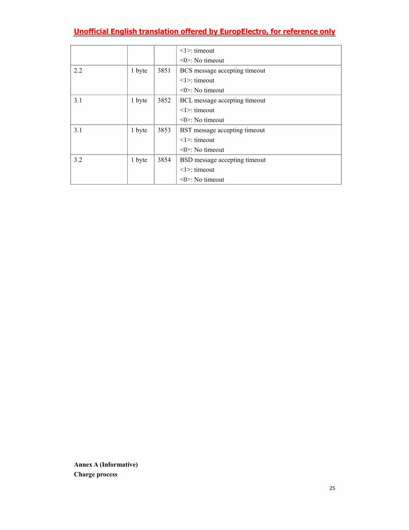
b) PGN7936 charger error message (CEM)
Message purpose: Charge error reason message is sent to BMS when the charger detect an error.
PGN message format is shown in Table 28.
Table28-PGN 7936 message format
Start bit/byte Length SPN SPN definition
1.1 1 byte 3848 BMS identifying message accepting timeout
<1>: timeout
<0>: No timeout
1.2 1 byte 3849 BCP message accepting timeout
<1>: timeout
<0>: No timeout
2.1 1 byte 3850 BRO message accepting timeout
Unofficial English translation offered by EuropElectro, for reference only
25
<1>: timeout
<0>: No timeout
2.2 1 byte 3851 BCS message accepting timeout
<1>: timeout
<0>: No timeout
3.1 1 byte 3852 BCL message accepting timeout
<1>: timeout
<0>: No timeout
3.1 1 byte 3853 BST message accepting timeout
<1>: timeout
<0>: No timeout
3.2 1 byte 3854 BSD message accepting timeout
<1>: timeout
<0>: No timeout
Annex A (Informative)
Charge process
Unofficial English translation offered by EuropElectro, for reference only
26
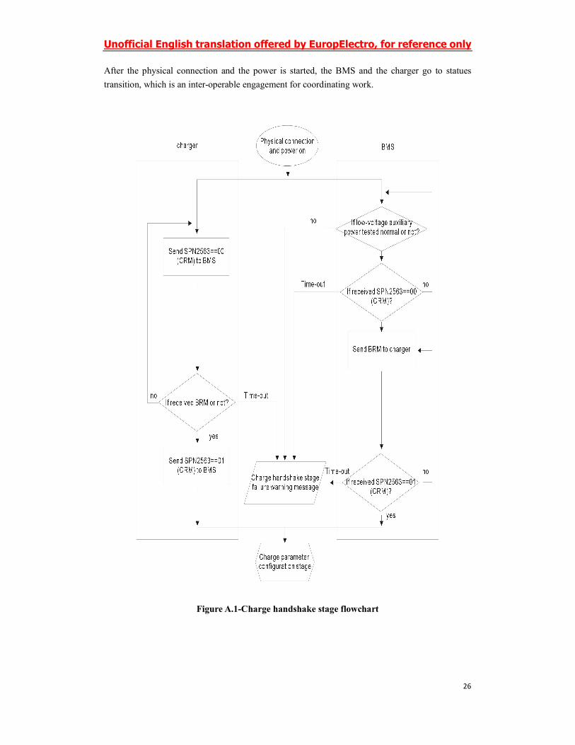
After the physical connection and the power is started, the BMS and the charger go to statues
transition, which is an inter-operable engagement for coordinating work.
Figure A.1-Charge handshake stage flowchart
Unofficial English translation offered by EuropElectro, for reference only
27
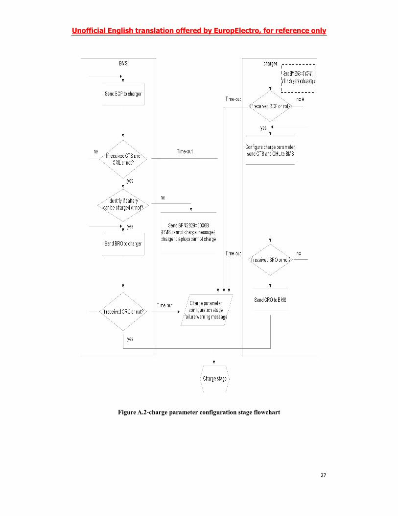
Figure A.2-charge parameter configuration stage flowchart
Unofficial English translation offered by EuropElectro, for reference only
28
FigureA.3-charging stage flowchart
Unofficial English translation offered by EuropElectro, for reference only
29
FigureA.4-Charge ending stage flowchart
Unofficial English translation offered by EuropElectro, for reference only
30
Annex B (Informative)
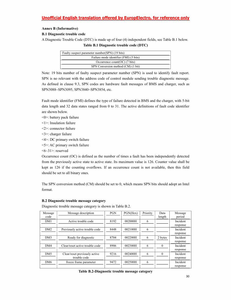
B.1 Diagnostic trouble code
A Diagnostic Trouble Code (DTC) is made up of four (4) independent fields, see Table B.1 below.
Table B.1 Diagnostic trouble code (DTC)
Note: 19 bits number of faulty suspect parameter number (SPN) is used to identify fault report.
SPN is no relevant with the address code of control module sending trouble diagnostic message.
As defined in clause 9.3, SPN codes are hardware fault messages of BMS and charger, such as
SPN3088~SPN3095, SPN3840~SPN3854, etc.
Fault mode identifier (FMI) defines the type of failure detected in BMS and the charger, with 5-bit
data length and 32 data states ranged from 0 to 31. The active definitions of fault code identifier
are shown below.
<0>: battery pack failure
<1>: Insulation failure
<2>: connector failure
<3>: charger failure
<4>: DC primary switch failure
<5>: AC primary switch failure
<6~31>: reserved
Occurrence count (OC) is defined as the number of times a fault has been independently detected
from the previously active state to active state. Its maximum value is 126. Counter value shall be
kept as 126 if the counting overflows. If an occurrence count is not available, then this field
should be set to all binary ones.
The SPN conversion method (CM) should be set to 0, which means SPN bits should adopt an Intel
format.
B.2 Diagnostic trouble message category
Diagnostic trouble message category is shown in Table B.2.
Table B.2-Diagnostic trouble message category
Faulty suspect parameter number(SPN) (19 bits)
Failure mode identifier (FMI) (5 bits)
Occurrence count(OC) (7 bits)
SPN Conversion method (CM) (1 bit)
Message
code
Message description PGN PGN(Hex) Priority Data
length
Message
period
DM1 Active trouble code 8192 002000H 6 Incident
response
DM2 Previously active trouble code 8448 002100H 6 Incident
response
DM3 Ready for diagnostic 8704 002200H 6 2 bytes Incident
response
DM4 Clear/reset active trouble code 8906 002300H 6 0 Incident response
DM5 Clear/reset previously active
trouble code
9216 002400H 6 0 Incident
response
DM6 freeze frame parameter 9472 002500H 6 Incident
response
Unofficial English translation offered by EuropElectro, for reference only
31
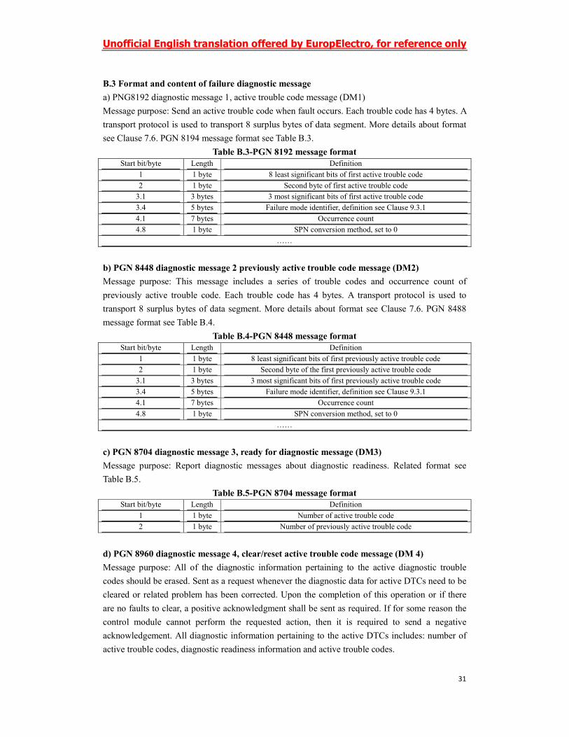
B.3 Format and content of failure diagnostic message
a) PNG8192 diagnostic message 1, active trouble code message (DM1)
Message purpose: Send an active trouble code when fault occurs. Each trouble code has 4 bytes. A
transport protocol is used to transport 8 surplus bytes of data segment. More details about format
see Clause 7.6. PGN 8194 message format see Table B.3.
Table B.3-PGN 8192 message format
Start bit/byte Length Definition
1 1 byte 8 least significant bits of first active trouble code
2 1 byte Second byte of first active trouble code
3.1 3 bytes 3 most significant bits of first active trouble code
3.4 5 bytes Failure mode identifier, definition see Clause 9.3.1
4.1 7 bytes Occurrence count
4.8 1 byte SPN conversion method, set to 0
……
b) PGN 8448 diagnostic message 2 previously active trouble code message (DM2)
Message purpose: This message includes a series of trouble codes and occurrence count of
previously active trouble code. Each trouble code has 4 bytes. A transport protocol is used to
transport 8 surplus bytes of data segment. More details about format see Clause 7.6. PGN 8488
message format see Table B.4.
Table B.4-PGN 8448 message format
Start bit/byte Length Definition
1 1 byte 8 least significant bits of first previously active trouble code
2 1 byte Second byte of the first previously active trouble code
3.1 3 bytes 3 most significant bits of first previously active trouble code
3.4 5 bytes Failure mode identifier, definition see Clause 9.3.1
4.1 7 bytes Occurrence count
4.8 1 byte SPN conversion method, set to 0
……
c) PGN 8704 diagnostic message 3, ready for diagnostic message (DM3)
Message purpose: Report diagnostic messages about diagnostic readiness. Related format see
Table B.5.
Table B.5-PGN 8704 message format
Start bit/byte Length Definition
1 1 byte Number of active trouble code
2 1 byte Number of previously active trouble code
d) PGN 8960 diagnostic message 4, clear/reset active trouble code message (DM 4)
Message purpose: All of the diagnostic information pertaining to the active diagnostic trouble
codes should be erased. Sent as a request whenever the diagnostic data for active DTCs need to be
cleared or related problem has been corrected. Upon the completion of this operation or if there
are no faults to clear, a positive acknowledgment shall be sent as required. If for some reason the
control module cannot perform the requested action, then it is required to send a negative
acknowledgement. All diagnostic information pertaining to the active DTCs includes: number of
active trouble codes, diagnostic readiness information and active trouble codes.
Unofficial English translation offered by EuropElectro, for reference only
32
e) PGN 9216 diagnostic message 5, clear/reset previously active trouble code message (DM5)
Message purpose: All of the diagnostic information pertaining to the previously active trouble
codes should be erased when this PG is requested. The diagnostic data associated with the active
trouble codes will not be affected. Upon the completion of this operation or if there are no fault to
clear, a positive acknowledgment shall be sent as required. If for some reason the control module
cannot perform the requested action, then it is required to send a negative acknowledgement. All
diagnostic information pertaining to the previously active DTCs includes: number of previously
active trouble codes, diagnostic readiness information and previously active trouble codes.
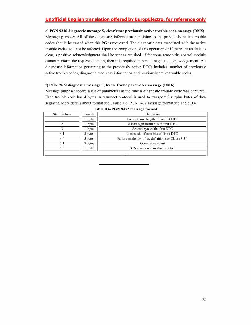
f) PGN 9472 diagnostic message 6, freeze frame parameter message (DM6)
Message purpose: record a list of parameters at the time a diagnostic trouble code was captured.
Each trouble code has 4 bytes. A transport protocol is used to transport 8 surplus bytes of data
segment. More details about format see Clause 7.6. PGN 9472 message format see Table B.6.
Table B.6-PGN 9472 message format
Start bit/byte Length Definition
1 1 byte Freeze frame length of the first DTC
2 1 byte 8 least significant bits of first DTC
3 1 byte Second byte of the first DTC
4.1 3 bytes 3 most significant bits of first t DTC
4.4 5 bytes Failure mode identifier, definition see Clause 9.3.1
5.1 7 bytes Occurrence count
5.8 1 byte SPN conversion method, set to 0
……