Embed Size (px)
Citation preview
СЕ308САНТ.411152.107-05.1 РЭ Operation Manual
Manufacturer:Electrotechnical Factories Energomera JSC415 Lenina Str., Stavropol, Russia 355029Tel.: (8652) 35-75-27, Fax: 56-66-90, Hot line (free): 8-800-200-75-27 e-mail: [email protected] www.energomera.ruWarranty service:217 Gagarina street, Nevinnomyssk, Stavropol region, 357106
Electric energy meterThree-phase multifunctional
Case type S31, S34
OKP 42 2863 6Harmonized System Codes (TN VED) 9028301 100

2
2 3
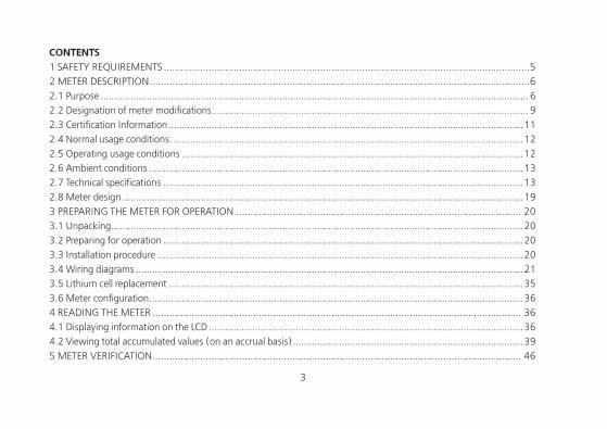
CONTENTS 1 SAFETY REQUIREMENTS ...................................................................................................................................52 METER DESCRIPTION ........................................................................................................................................62.1 Purpose .............................................................................................................................................................. 62.2 Designation of meter modifications ..................................................................................................................... 92.3 Certification Information ...................................................................................................................................112.4 Normal usage conditions: .................................................................................................................................122.5 Operating usage conditions ..............................................................................................................................122.6 Ambient conditions ..........................................................................................................................................132.7 Technical specifications .....................................................................................................................................132.8 Meter design ....................................................................................................................................................193 PREPARING THE METER FOR OPERATION....................................................................................................... 203.1 Unpacking ........................................................................................................................................................203.2 Preparing for operation .....................................................................................................................................203.3 Installation procedure .......................................................................................................................................203.4 Wiring diagrams ...............................................................................................................................................213.5 Lithium cell replacement ...................................................................................................................................353.6 Meter configuration ..........................................................................................................................................364 READING THE METER .................................................................................................................................... 364.1 Displaying information on the LCD ....................................................................................................................364.2 Viewing total accumulated values (on an accrual basis) .....................................................................................395 METER VERIFICATION .................................................................................................................................... 46
4
6 MAINTENANCE AND SEALING....................................................................................................................... 467 ROUTINE MAINTENANCE .............................................................................................................................. 478 STORAGE AND TRANSPORTATION CONDITIONS ............................................................................................ 489 CONTAINERS AND PACKING .......................................................................................................................... 4810 LABELING .................................................................................................................................................... 49ANNEX A .......................................................................................................................................................... 51ANNEX B .......................................................................................................................................................... 52ANNEX C .......................................................................................................................................................... 54
4 5
This САНТ.411152.107-05.1 РЭ (Operation Manual) contains brief information on CE308 S31, CE308 S34 multifunctional three-phase electric meter (hereinafter referred to as the «Meter»). Complete information on the above meter is contained in САНТ.411152.107-05.1 РП (User Manual), which can be found at the manufacturer’s website: www.energomera.ru/ru/products/meters/ce308-all
When learning about the meter and operating it, you must be additionally guided by САНТ.411152.107-05.1 ФО (Technical passport) (included in the meter delivery kit) and САНТ.411152.107-05.1 РП (User Manual).
Only persons who have received special training for working with voltages up to 1000 V and who have studied the Operation Manual are allowed to work with the meter.
1 SAFETY REQUIREMENTS
1.1 By operational safety, the meter meets the safety requirements of GOST 22261-94 and IEC 61010-1:2001.1.2 According to the method for protecting a person from electric shock, the meter corresponds to class II of
IEC 61010-1:2001.1.3 The insulation between all current and voltage circuits connected together and with the «ground» can
withstand a voltage of 4 kV AC at 50 Hz for 1 minute. During the test, the leads of the electrical test output device, the interface circuits are connected to the «ground» (the «ground» is a conductive foil film enclosing the meter and attached to a flat conductive surface on which the meter base is mounted).
For transformer connection meters, the insulation withstands a voltage of 4 kV AC at 50 Hz for 1 minute, when applied between current circuits connected together and voltage circuits connected together.
1.4 For transformer connection meters, the insulation between each current circuit and all other meter circuits connected to the «ground»; between each voltage circuit and all other meter circuits, including the common voltage circuit output connected to the «ground», withstands pulse voltage of 6 kV.
The insulation between all current and voltage circuits connected together and with the «ground» can withstand pulse voltage of 6 kV. During the test, the leads of the electrical test output device must be connected to the «ground».
6
1.5 Insulation resistance between the casing and electrical circuits, at least:20 MΩ — under conditions of clause 2.5;7 MΩ – at an ambient air temperature (40±2) °С, relative air humidity of 93%.1.6 The meter must be installed and operated in accordance with the applicable rules for technical operation of
electrical installations.1.7 Do not put foreign objects on the meter, avoid bumps.
2 METER DESCRIPTION
2.1 PurposeThe meter is three-phase, transformer connection or direct connection (depending on the version), it is designed
to measure active and reactive electrical energy in three-phase four-wire AC circuits.The meter has the following functions:• multi-tariff electricity metering (with three tariffing levels - event-based, external and time-based tariffing);• maintenance of the retrospective (recording the current values of energy storage devices: at the end of the
billing period (month), at the end of the day, at the end of the year and upon occurrence of a specific event);• maintaining a load profile, with the ability to customize the type of the parameters stored and the averaging
time;• measuring network parameters: voltage frequency, phase currents, phase voltages, phase-to-phase (line)
voltages (with non-standardized accuracy), angles between current and voltage by phases; power factor by phases and the three-phase power factor, active, reactive, full power by phases and total;
• measuring Unified Power Quality Index (UPQI) in accordance with class «S» of the measurement process specifications in IEC 61000-4-30:2008: stable voltage deviation, network frequency deviation, duration and depth of voltage dips, duration and maximum value of overvoltage, interruptions in power supply;
• power quality analysis for compliance with quality standards in accordance with EN50160:2010;• indicating the instance of violating an individual power quality indicator on the LCD (disabled by default);
6 7
• recording the violation of an individual power quality indicator (event logs available for reading on the interface);• monitoring active power consumption;• monitoring «instantaneous power» consumption;• monitoring active energy consumption (control of energy limits, prepaid mode, low consumption control);• monitoring mains voltage;• monitoring currents;• monitoring network frequency;• monitoring phase sequence;• monitoring phase break;• monitoring oncoming power flow;• alarm relay (in the versions of the meter with an alarm relay (see Table 2.2));• telemetric outputs with the ability to use them as a «relay»;• alarm using the interface (the ability to act as an initiator of communication with the level of DCU or HES during:
terminal cover opening; exposure to a magnetic field; reparameterization; maximum power excess; deviation from the normalized value of voltage level, etc., in accordance with the full list, for details, see the user manual САНТ.411152.107-05.1 РП;
• time accounting;• self-diagnostics;• information protection;• protection against unauthorized opening (electronic seals);• magnetic field sensor;• event logs with recording of: terminal cover opening; case opening; dates of last re-programming; exposure
to a magnetic field causing unacceptable deviations of the metrological characteristics of the metering device; facts of communication with the metering device that led to data changes; voltage deviations from the device’s nominal values in the measuring circuits; results of self-diagnostics; changes in the current values of time and date during time synchronization (at least 3,500 records using the DLMS/COSEM protocol.), etc., for details, see the user
8
manual САНТ.411152.107-05.1 РП;• mechanism for flexible adjustment of the reaction to events occurring in the meter;• DLMS/COSEM exchange protocol support;• display of information on the LCD accompanied by OBIS codes;• IEC 60870-5-104-2004 exchange protocol support;• management of consumer load according to a predefined schedule.A detailed description of meter functions is given in the full version of САНТ.411152.107-05.1 РП (User
Manual).The meter can be used in Automatic Informational and Measuring Systems for Commercial Electric Power
Accounting (AMI systems) to transfer the measured or calculated parameters to the control room for controlling, accounting and distributing electric power.
The measurement results are obtained through processing and calculating current and voltage input signals performed by the microprocessor circuit on the meter board. The measured data and other information are displayed on a liquid crystal display (LCD) and can be transmitted via an optical port, using one or two additional interfaces.
The meter has 2 communication channels. The PLC G3 communication module in metering devices operates on the principle of a mesh network and provides search for duplicate routes for the guaranteed transmission of the collected information.
The meter has an electronic counting mechanism which, depending on the established current and voltage transformation ratios, records active and reactive energy in kW•h and kVar•h, respectively, overall and according to eight tariffs in two directions.
Changing time of the counting mechanism indications complies with the requirements of IEC 62052-11:2003, IEC 62053-21:2003 (IEC 62053-22:2003) and IEC 62053-23:2003.
8 9
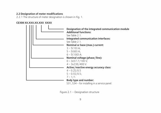
2.2 Designation of meter modifications2.2.1 The structure of meter designation is shown in Fig. 1.
СЕ308 XX.ХXХ.XХ.XXX XXXX
Designation of the integrated communication moduleAdditional functions:See Table 2.1.Integrated communication interfaces:See Table 2.1.Nominal or base (max.) current:3 – 5(10) А;5 – 5(60) А;6 – 5(100) А.Nominal voltage (phase/line):0 – 3x57.7/100 V;4 – 3x230/400 V.Active/reactive energy accuracy class:4 – 0.2S/0.55 – 0.5S/0.5; 7 – 1/1.Body type and number:S31, S34 – for installing in a service panel.
Figure 2.1 – Designation structure
10
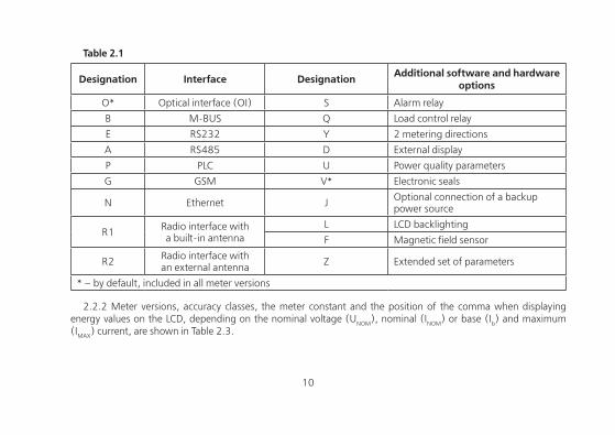
Table 2.1
Designation Interface Designation Additional software and hardware options
O* Optical interface (OI) S Alarm relay
B M-BUS Q Load control relay
E RS232 Y 2 metering directions
A RS485 D External display
P PLC U Power quality parameters
G GSM V* Electronic seals
N Ethernet J Optional connection of a backup power source
R1 Radio interface witha built-in antenna
L LCD backlighting
F Magnetic field sensor
R2 Radio interface withan external antenna Z Extended set of parameters
* – by default, included in all meter versions
2.2.2 Meter versions, accuracy classes, the meter constant and the position of the comma when displaying energy values on the LCD, depending on the nominal voltage (UNOM), nominal (INOM) or base (Ib) and maximum (IMAX) current, are shown in Table 2.3.
10 11
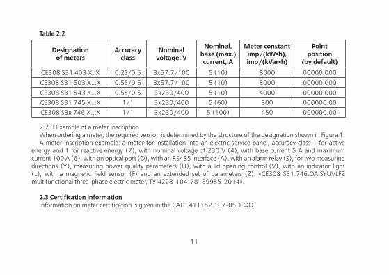
Table 2.2
Designationof meters
Accuracyclass
Nominalvoltage, V
Nominal, base (max.) current, A
Meter constantimp/(kW•h),imp/(kVar•h)
Pointposition
(by default)
СЕ308 S31 403 Х…X 0.2S/0.5 3х57.7/100 5 (10) 8000 00000.000
CE308 S31 503 Х...Х 0.5S/0.5 3x57.7/100 5 (10) 8000 00000.000
CE308 S31 543 Х...Х 0.5S/0.5 3x230/400 5 (10) 4000 00000.000
CE308 S31 745 Х...Х 1/1 3x230/400 5 (60) 800 000000.00
CE308 S3x 746 Х...Х 1/1 3x230/400 5 (100) 450 000000.00
2.2.3 Example of a meter inscriptionWhen ordering a meter, the required version is determined by the structure of the designation shown in Figure 1.A meter inscription example: a meter for installation into an electric service panel, accuracy class 1 for active
energy and 1 for reactive energy (7), with nominal voltage of 230 V (4), with base current 5 A and maximum current 100 A (6), with an optical port (O), with an RS485 interface (A), with an alarm relay (S), for two measuring directions (Y), measuring power quality parameters (U), with a lid opening control (V), with an indicator light (L), with a magnetic field sensor (F) and an extended set of parameters (Z): «CE308 S31.746.OA.SYUVLFZ multifunctional three-phase electric meter, TУ 4228-104-78189955-2014».
2.3 Certification InformationInformation on meter certification is given in the САНТ.411152.107-05.1 ФО.
12
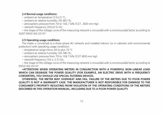
2.4 Normal usage conditions:– ambient air temperature (23±2) °С;– ambient air relative humidity (30-80) %;– atmospheric pressure from 70 to 106.7 kPa (537...800 mm Hg).– network frequency (50±0.5) Hz;– the shape of the voltage curve of the measuring network is sinusoidal with a nonsinusoidal factor according to
GOST EN50160:2010*.
2.5 Operating usage conditionsThe meter is connected to a three-phase AC network and installed indoors (or in cabinets with environmental
protection) with operating usage conditions:– temperature range minus 40 to plus 70 °С– ambient air relative humidity (30-98) %;– atmospheric pressure from 70 to 106.7 kPa (537-800 mm Hg).– network frequency (50 ± 2.5) Hz;– the shape of the voltage curve of the measuring network is sinusoidal with a nonsinusoidal factor according to
EN50160:2010*.*ATTENTION! WHEN OPERATING METERS IN CONJUNCTION WITH A POWERFUL NON-LINEAR LOAD
WHICH CAN DEGRADE THE POWER QUALITY (FOR EXAMPLE, AN ELECTRIC DRIVE WITH A FREQUENCY CONVERTER), YOU SHOULD USE SPECIAL FILTERING DEVICES.
OTHERWISE, THE METER MAY OVERHEAT AND FAIL. FAILURE OF THE METERS DUE TO POOR POWER QUALITY IS NOT A WARRANTY CASE. THE MANUFACTURER IS NOT RESPONSIBLE FOR DAMAGE TO THE CONSUMER’S PROPERTY RESULTING FROM VIOLATION OF THE OPERATING CONDITIONS OF THE METERS DESCRIBED IN THIS OPERATION MANUAL, INCLUDING DUE TO A POOR POWER QUALITY.
12 13
2.6 Ambient conditions
2.6.1 In terms of resistance to climatic influences, the meter belongs to group 4 in accordance with GOST 22261-94, with an extended range of temperature and humidity, satisfying version T category 3 in
accordance with GOST 15150-69.In terms of resistance to mechanical impacts, the meter belongs to group 2 according to GOST 22261-94.2.6.2 In terms of protection against ingress of dust, water and external solid objects, the meter case corresponds
to the degree of protection IP54 according to IEC 60529:2013. In case of outdoor use, the meter must be installed inside a protective box, protecting it from direct exposure to sunlight, precipitation and not allowing the temperature of the air surrounding the meter to rise above plus 70 ° C.
2.6.3 The meter is resistant against single impacts with a maximum acceleration of 300 m/s2.2.6.4 The meter is resistant to vibrations in the frequency range (10-150) Hz.2.6.5 The meter body withstands impact of spring hammer blows with kinetic energy (0.20±0.02) J applied to
the external surfaces of the body, including the windows, and to the lid of the clamps.2.6.6 Parts and components of the meter that are designed for operation in areas with a tropical climate, in terms
of resistance to the effects of mold fungi, comply with the requirements of GOST 9.048-89.The permissible growth of fungi amounts up to 3 points according to GOST 9.048-89.
2.7 Technical specifications2.7.1 The meters meet the requirements of IEC 62052-11:2003, IEC 62053-21:2003 (for class 1),
IEC 62053-22:2003 (for classes 0.2S and 0.5S) in terms of measuring active energy, and IEC 62053-23:2003 in terms of measuring reactive energy.
2.7.2 The technical specifications given with tolerances or limit values are considered guaranteed. Values without tolerances are for reference only.
Main technical specifications are given in Table 2.4.Limits of the permissible errors of the measured values are given in Annex A.
14
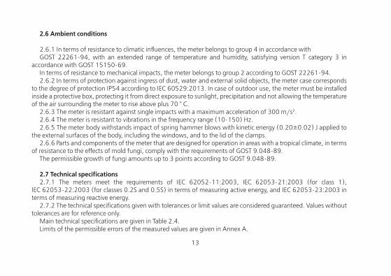
Table 2.3
Specification name Specification value Note
Nominal (max.) currents 5(10) А Transformer connection
Base (max.) currents 5(60); 5(100) Direct connection
Nominal phase voltage57.7 V; 230 V Transformer connection
230 V Direct connection
Operating phase voltage (0.6 (0.75)*...1.21) Unom V* — for meters with 57.7 V
nominal voltage
Nominal network frequency (50±2.5) Hz
Non-sinusoidal factor of the measuring network voltage, %, max
– In accordance with EN50160:2010
Sensitivity threshold
Directconnection
Transformer connection
Active/reactive energy
– 0.001 Inom A 0.2S/0.5; 0.5S/0.5
0.002 Ib A 1/1
Number of decimal places on the LCD from Table 2.2
Total power consumed by each current circuit, max
0.1 (V•A) With nominal (base) current
14 15
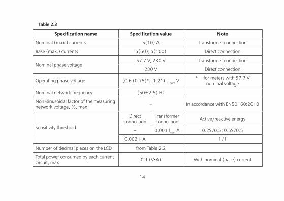
Specification name Specification value Note
Total (active) power (consumed by each voltage circuit at nominal voltage, max
9(V•A) (0.8 W) Transformer connection
Active power consumption of communication modules, max
3 W at nominal voltage
Limit of the clock basic absolute error ±0.5 s/day Transformer connection
Manual and system correction, clock rate
±29 s max 29 s per day
Limit of the clock additional temperature error
±0.15 s/°C•day From minus 10 to 45 °С
±0.2 s/°C•dayFrom minus 40 to minus 10 °С
and from 45 to plus 70 °С
Duration of information storage when power is off
30 years
Built-in lithium cell service life 16 yearsIt is possible to install an additional
external lithium cell (see section 3.5)
Additional external lithium cell service life
5 years
Number of tariffs up to 8
Table 2.3 (continued)
16
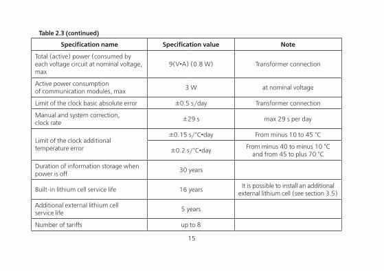
Specification name Specification value Note
Number of tariff zones in a day up to 16
Number of seasonal schedules in a year up to 12
Number of exclusive days up to 80
Number of daily rate scales up to 32
Number of power control zonesin a day
3
Number of power control schedules up to 12
Power averaging time1; 2; 3; 4; 5; 6; 10; 12; 15;
20, 30, 60 min
Depth of monthly energy storageby tariffs and phases
40 months Current and 39 previous
Depth of daily energy storage, accumulated by tariffs and phases
128 days Current and 127 previous
Depth of annual energy storage, accumulated by tariffs and phases
10 years Current and 9 previous
Depth of event energy storage by tariffs and phases
20 events
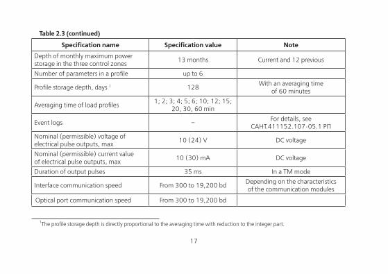
Table 2.3 (continued)
16 17
Specification name Specification value Note
Depth of monthly maximum power storage in the three control zones
13 months Current and 12 previous
Number of parameters in a profile up to 6
Profile storage depth, days 1 128With an averaging time
of 60 minutes
Averaging time of load profiles1; 2; 3; 4; 5; 6; 10; 12; 15;
20, 30, 60 min
Event logs –For details, see
САНТ.411152.107-05.1 РП
Nominal (permissible) voltage of electrical pulse outputs, max
10 (24) V DC voltage
Nominal (permissible) current value of electrical pulse outputs, max
10 (30) mA DC voltage
Duration of output pulses 35 ms In a TM mode
Interface communication speed From 300 to 19,200 bdDepending on the characteristicsof the communication modules
Optical port communication speed From 300 to 19,200 bd
1The profile storage depth is directly proportional to the averaging time with reduction to the integer part.
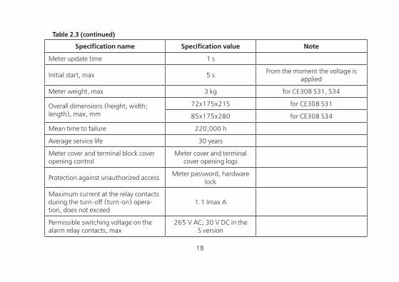
Table 2.3 (continued)
18
Specification name Specification value Note
Meter update time 1 s
Initial start, max 5 sFrom the moment the voltage is
applied
Meter weight, max 3 kg for CE308 S31, S34
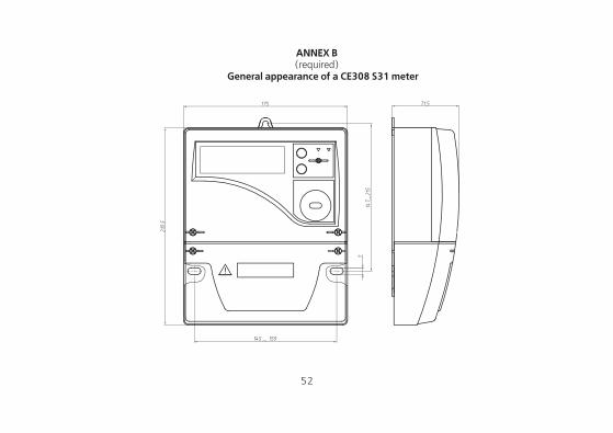
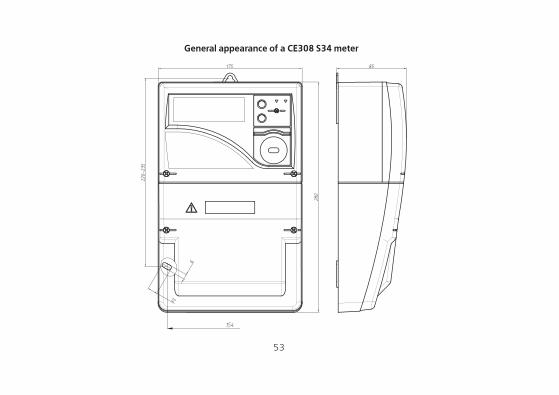
Overall dimensions (height; width; length), max, mm
72х175х215 for CE308 S31
85х175х280 for CE308 S34
Mean time to failure 220,000 h
Average service life 30 years
Meter cover and terminal block cover opening control
Meter cover and terminal cover opening logs
Protection against unauthorized accessMeter password, hardware
lock
Maximum current at the relay contacts during the turn-off (turn-on) opera-tion, does not exceed
1.1 Imax А
Permissible switching voltage on the alarm relay contacts, max
265 V AC; 30 V DC in the S version
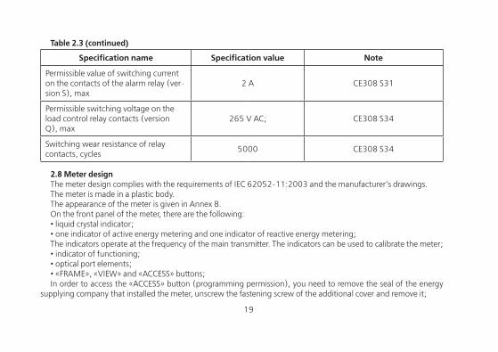
Table 2.3 (continued)
18 19
Specification name Specification value Note
Permissible value of switching current on the contacts of the alarm relay (ver-sion S), max
2 А CE308 S31
Permissible switching voltage on the load control relay contacts (version Q), max
265 V AC; CE308 S34
Switching wear resistance of relay contacts, cycles
5000 CE308 S34
2.8 Meter designThe meter design complies with the requirements of IEC 62052-11:2003 and the manufacturer’s drawings.The meter is made in a plastic body.The appearance of the meter is given in Annex B.On the front panel of the meter, there are the following:• liquid crystal indicator;• one indicator of active energy metering and one indicator of reactive energy metering;The indicators operate at the frequency of the main transmitter. The indicators can be used to calibrate the meter;• indicator of functioning;• optical port elements;• «FRAME», «VIEW» and «ACCESS» buttons;In order to access the «ACCESS» button (programming permission), you need to remove the seal of the energy
supplying company that installed the meter, unscrew the fastening screw of the additional cover and remove it;
Table 2.3 (continued)
20
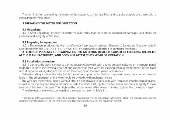
The terminals for connecting the meter to the network, to interface lines and to pulse outputs are closed with a transparent terminal cover.
3 PREPARING THE METER FOR OPERATION
3.1 Unpacking3.1.1 After unpacking, inspect the meter visually, verify that there are no mechanical damages, and check the
presence and integrity of the seals.
3.2 Preparing for operation3.2.1 The meters produced by the manufacturer have factory settings. Changes to factory settings are made in
accordance with the САНТ.411152.107-05.1 РП by companies authorized to configure the meter.ATTENTION! PRESENCE OF READINGS ON THE METERING DEVICE IS CAUSED BY CHECKING THE METER
AT THE MANUFACTURER’S, AND DOES NOT ATTEST TO ITS WEAR OR OPERATION.
3.3 Installation procedure3.3.1 Connect the electric meter to a three-phase AC network with a rated voltage indicated on the meter panel.
To do this, remove the terminal cover of and connect the lead wires by securing them in the terminals of the block according to the wiring diagram printed on the cover, or on the front panel, or in Annex C.
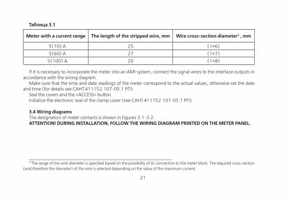
When installing a meter, the wire (cable)2 must be stripped of insulation to approximately the amount shown in Table 4. The stripped part of the wire should be smooth, without bends. Insert
the wire into the terminal clamp without tilts. It is not allowed to get a wire with insulation into the clamping area, as well as for the stripped area to protrude outside the block. First, tighten the top screw. Pull the wire lightly to make sure that it has been clamped. Then tighten the bottom screw. After several minutes, tighten the connection again.
The diameter of the wires connected to the meter is shown in Table 3.1. 2 The range of the wire diameter is specified based on the possibility of its connection to the meter block. The required cross-section
(and therefore the diameter) of the wire is selected depending on the value of the maximum current.
20 21
Таблица 3.1
Meter with a current range The length of the stripped wire, mm Wire cross-section diameter3 , mm
5(10) А 25 (1÷6)
5(60) А 27 (1÷7)
5(100) А 20 (1÷8)
If it is necessary to incorporate the meter into an AMI system, connect the signal wires to the interface outputs in accordance with the wiring diagram.
Make sure that the time and date readings of the meter correspond to the actual values, otherwise set the date and time (for details see САНТ.411152.107-05.1 РП).
Seal the covers and the «ACCESS» button.Initialize the electronic seal of the clamp cover (see САНТ.411152.107-05.1 РП).
3.4 Wiring diagramsThe designation of meter contacts is shown in Figures 3.1-3.2.ATTENTION! DURING INSTALLATION, FOLLOW THE WIRING DIAGRAM PRINTED ON THE METER PANEL.
3 The range of the wire diameter is specified based on the possibility of its connection to the meter block. The required cross-section
(and therefore the diameter) of the wire is selected depending on the value of the maximum current.
22
1 2 43 7 865 161514131211109 19
SIM cardconnector
SIM
1 2 43 7 865 161514131211109 1917 18
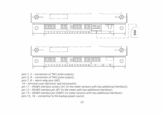
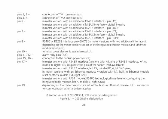
pins 1, 2 – connection of TM1 pulse outputs;pins 3, 4 — connection of TM2 pulse outputs;pins 7, 8 — alarm relay pins (AR);10 – terminal cover electronic seal microswitch;pin 11 – RS485 interface contact (A’) (in the meter versions with two additional interfaces);pin 12 – RS485 interface pin (B’) (in the meter with two additional interfaces);pin 13 – RS485 interface pin (GND’) (in meter versions with two additional interfaces); pins 15, 16 – connection to the backup power source;
22 23
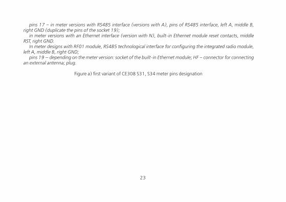
pins 17 – in meter versions with RS485 interface (versions with A), pins of RS485 interface, left A, middle B, right GND (duplicate the pins of the socket 19);
in meter versions with an Ethernet interface (version with N), built-in Ethernet module reset contacts, middle RST, right GND.
In meter designs with RF01 module, RS485 technological interface for configuring the integrated radio module, left A, middle B, right GND;
pins 19 — depending on the meter version: socket of the built-in Ethernet module; HF – connector for connecting an external antenna; plug.
Figure a) first variant of CE308 S31, S34 meter pins designation
24
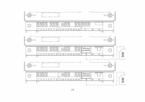
1 2 43 7 865 161514131211109 1917 18
1 2 43 7 865 161514131211109 1918
SIM cardconnector
SIM
1 2 43 7 865 161514131211109 1918
SIM cardconnector
SIM
24 25
pins 1, 2 – connection of TM1 pulse outputs;pins 3, 4 – connection of TM2 pulse outputs;pin 6 – in meter versions with an additional RS485 interface – pin (A’);
in meter versions with an additional M-BUS interface – digital line pin; in meter versions with an additional RS232 interface – pin (TX’);
pin 7 – in meter versions with an additional RS485 interface – pin (B’); in meter versions with an additional M-BUS interface – digital line pin; in meter versions with an additional RS232 interface – pin (RX’);
pin 8 – RS485 or RS232 interface pin (GND’) (in meter versions with two additional interfaces); depending on the meter version: socket of the integrated Ethernet module and Ethernet
module reset pins;pin 10 – terminal cover electronic seal microswitch;pins 11, 12 – alarm relay pins (AR);pins 15, 16 – connection to the backup power source;pin 17 – in meter versions with RS485 interface (versions with A), pins of RS485 interface, left A,
middle B, right GND (duplicate the pins of the socket 19 if available); in meter versions with RS232 interface, left TX, middle RX, right GND pins; in meter versions with an Ethernet interface (version with N), built-in Ethernet module
reset contacts, middle RST, right GND. in meter versions with RF01 module, RS485 technological interface for configuring the
integrated radio module, left A, middle B, right GND;pin 19 – depending on the meter version: socket of the built-in Ethernet module; HF – connector
for connecting an external antenna; plug.
b) second variant of CE308 S31, S34 meter pins designationFigure 3.1 – СЕ308 pins designation
26
1 2 43 8765 109
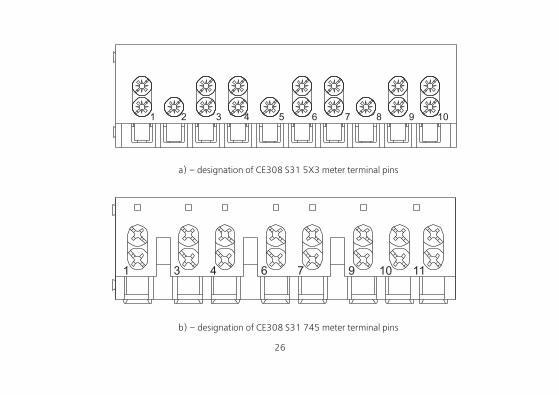
a) – designation of CE308 S31 5X3 meter terminal pins
976431 10 11
b) – designation of CE308 S31 745 meter terminal pins
26 27
1 3 4 6 9 10 117
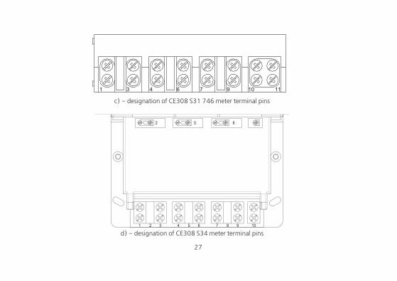
c) – designation of CE308 S31 746 meter terminal pins
d) – designation of CE308 S34 meter terminal pins
28
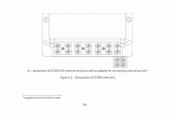
e) – designation of CE308 S34 meter terminal pins with an adapter for connecting a second zero pin4
Figure 3.2 – Designation of CE308 meter pins
4 Supplied with the CE308 S34 meter
28 29
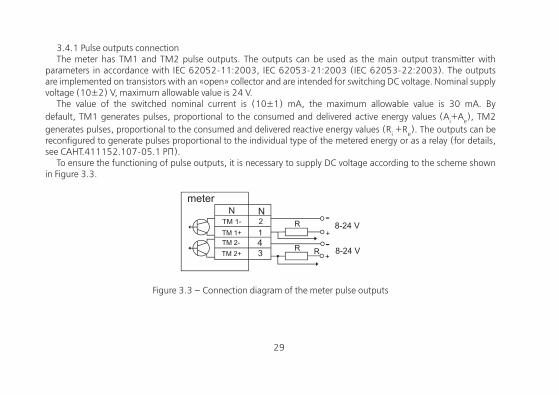
3.4.1 Pulse outputs connectionThe meter has ТМ1 and ТМ2 pulse outputs. The outputs can be used as the main output transmitter with
parameters in accordance with IEC 62052-11:2003, IEC 62053-21:2003 (IEC 62053-22:2003). The outputs are implemented on transistors with an «open» collector and are intended for switching DC voltage. Nominal supply voltage (10±2) V, maximum allowable value is 24 V.
The value of the switched nominal current is (10±1) mA, the maximum allowable value is 30 mA. By default, ТМ1 generates pulses, proportional to the consumed and delivered active energy values (Ai+Ae), ТМ2 generates pulses, proportional to the consumed and delivered reactive energy values (Ri +Re). The outputs can be reconfigured to generate pulses proportional to the individual type of the metered energy or as a relay (for details, see САНТ.411152.107-05.1 РП).
To ensure the functioning of pulse outputs, it is necessary to supply DC voltage according to the scheme shown in Figure 3.3.
Figure 3.3 – Connection diagram of the meter pulse outputs
30
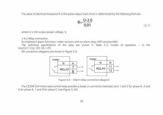
The value of electrical resistance R in the pulse output load circuit is determined by the following formula:
(3.1)
where U is the output power voltage, V.
3.4.2 Relay connectionTo implement alarm functions, meter versions with an alarm relay (AR) are provided:The switching specifications of the relay are shown in Table 2.3, modes of operation – in the
САНТ.411152.107-05.1 РП.AR connection diagrams are shown in Figure 3.4.
Figure 3.4 – Alarm relay connection diagram
The CE308 S34 meter load control relay provides a break or connection between pins 1 and 3 for phase A, 4 and 6 for phase B, 7 and 9 for phase C (see Figure 3.2d).
30 31
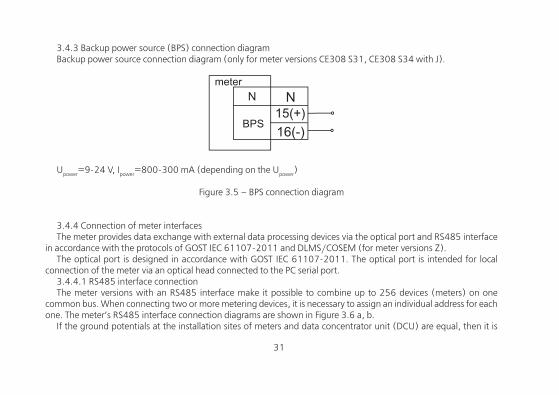
3.4.3 Backup power source (BPS) connection diagramBackup power source connection diagram (only for meter versions CE308 S31, СЕ308 S34 with J).
Upower=9-24 V, Ipower=800-300 mA (depending on the Upower)
Figure 3.5 – BPS connection diagram
3.4.4 Connection of meter interfacesThe meter provides data exchange with external data processing devices via the optical port and RS485 interface
in accordance with the protocols of GOST IEC 61107-2011 and DLMS/COSEM (for meter versions Z).The optical port is designed in accordance with GOST IEC 61107-2011. The optical port is intended for local
connection of the meter via an optical head connected to the PC serial port.3.4.4.1 RS485 interface connectionThe meter versions with an RS485 interface make it possible to combine up to 256 devices (meters) on one
common bus. When connecting two or more metering devices, it is necessary to assign an individual address for each one. The meter’s RS485 interface connection diagrams are shown in Figure 3.6 a, b.
If the ground potentials at the installation sites of meters and data concentrator unit (DCU) are equal, then it is

32
enough to connect pin 17 (right) and 13 (for CE308 S31, S34) to the zero potential point, otherwise take potential equalization measures.
In the event that the length of the communication lines does not exceed several meters and there are no sources of interference, then the connection diagram can be significantly simplified by connecting the meter to the DCU or PC using only two signal wires A and B. The exact resistance value of the terminal resistors5 , as well as the need to use them, should be determined during the preliminary survey of the facility. In general, if the communication line is up to 1000 m and the exchange rate is up to 9600 bod, the use of terminal resistors is not recommended6.
а) connecting CE308 S31, S34 using connector 17 (see Figure 3.1a)
Biasing resistors (+R) and (-R) (nominal 100 kΩ) are installed in the meter and are always connected to the A and B lines, respectively. Unused biasing resistors with resistance of 560 Ω are also installed. To activate the resistors, it is necessary to close the contact pads located in the area of connector 19 (see Figure 3.1a): «R-» with «B», «R+»
5 It also depends on the cable brand, its length, linear resistance, as well as the input impedance of all other receivers in the line6 If the terminal resistor is already installed inside the data concentrator unit, it can be disconnected using the appropriate
microswitches (jumpers) of the data concentrator unit.
32 33
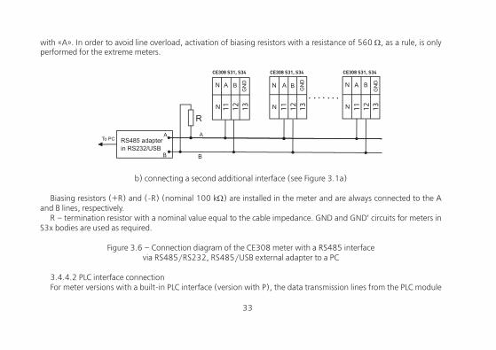
with «A». In order to avoid line overload, activation of biasing resistors with a resistance of 560 Ω, as a rule, is only performed for the extreme meters.
11 12 13 11 12 13 11 12 13
СЕ308 S31, S34 СЕ308 S31, S34 СЕ308 S31, S34
b) connecting a second additional interface (see Figure 3.1a)
Biasing resistors (+R) and (-R) (nominal 100 kΩ) are installed in the meter and are always connected to the A and B lines, respectively.
R – termination resistor with a nominal value equal to the cable impedance. GND and GND’ circuits for meters in S3x bodies are used as required.
Figure 3.6 – Connection diagram of the CE308 meter with a RS485 interface via RS485/RS232, RS485/USB external adapter to a PC
3.4.4.2 PLC interface connectionFor meter versions with a built-in PLC interface (version with P), the data transmission lines from the PLC module
34
of the meter are connected from the phase C output (output 8) and neutral (outputs 10, 11) (for details, see САНТ.411152.107-05.1 РП).
3.4.4.3 GSM interface connectionFor meter versions with a built-in GSM interface (versions with G), install a SIM card with a positive balance and
a connected data transmission service in the slot and connect a remote antenna to connector 19 (see Figure 3.1b). Then, see САНТ.411152.107-05.1 РП.
3.4.4.4 Ethernet interface connectionFor meter versions with a built-in Ethernet interface (versions with N), connect one end of the Ethernet cable to
connector 19 (see Figure 3.1a), and the other end to the PC network card. Then, see САНТ.411152.107-05.1 РП.
3.4.4.5 Radio interface connectionSee САНТ.411152.107-05.1 РП.
3.4.4.6 To exchange data via the optical interface, a readout head in accordance with GOST IEC61107-2011 is used. See САНТ.411152.107-05.1 РП.
3.4.4.7 M-BUS interface connectionThe meter implements the physical layer of the M-BUS interface in accordance with EN 13757-2 standard. See
САНТ.411152.107-05.1 РП.
3.4.4.8 RS232 interface connection.See САНТ.411152.107-05.1 РП.
34 35
3.5 Lithium cell replacementIn the meter, an integrated CR14250BL-VY lithium cell or equivalent is used for the real-time clock.The lithium cell should only be replaced by a service company or in the workshop of the power supplying
organization that is authorized to repair and check the meter.In the meter, it is necessary to remove the seals of the power supplying organization, the service department
and state verification, remove the meter cover, and remove the top meter board from the connector. Solder out the lithium cell from the board and replace it. To replace the lithium cell, it is necessary to comply with the polarity using the symbols on the board. CR14250BL-VY lithium cell by EEMB is recommended. The lithium cell should have the following technical specifications: supply voltage +3.0 V; capacity at least 900 (mA*h); working temperature range from minus 40 to 85 °C; self-discharge max 1% per year.
After replacing the lithium cell, set the date and time, initialize the electronic seal of the body (see the САНТ.411152.107-05.1 РП).
In the meter, it is possible to install an additional lithium cell (in case that the integrated cell is discharged) without opening the meter body. To connect (or replace) it, you must unscrew the cell compartment cover screw and remove the lithium cell container, solder out the lithium cell (if it was previously installed) and replace it. When replacing the lithium cell, mind the polarity according to the signs on the cell compartment. Panasonic BR2330 or equivalent lithium cell is recommended. The lithium cell should have the following technical specifications: supply voltage +3.0 V; capacity at least 255 (mA*h); working temperature range from minus 40 to 85 °C; self-discharge max 1% per year.
Note – When the meter is off, replacing the lithium cell will stop the clock (the «Attention» icon is displayed on the LCD), therefore, after replacing the lithium cell, the current time must be programmed (the «Attention» icon will disappear).
ATTENTION! When the meter is on, the battery has phase voltage. After replacing the lithium cell, install the board in its original place, close and seal the meter, and verify it. With each replacement, it is necessary to make a note in the Data Sheet – who replaced the lithium cell, when and the type of the replacement cell.
36
3.6 Meter configurationConfiguration is carried out according to the САНТ.411152.107-05.1 РП, which is available at the manufacturer’s
website www.energomera.ru/ru/products/meters/ce308-all
4 READING THE METER
The meter can be read both manually and in the automated mode.In the automated mode, full information on energy consumption can be obtained using a PC or AMI system via
the interface (see САНТ.411152.107-05.1 РП).In the manual mode, data is displayed on the LCD in a window eight decimal places wide (with a decimal point).
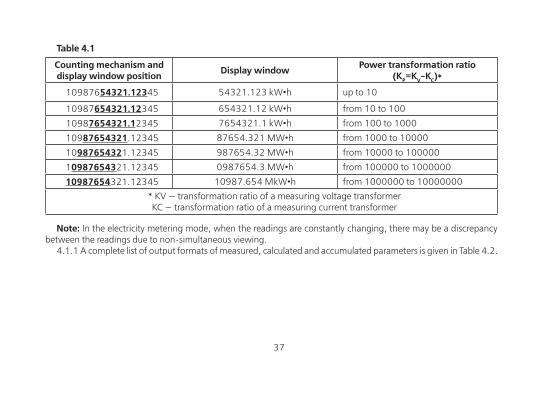
4.1 Displaying information on the LCDTo meet the requirements of IEC 62052-11:2003 to the counting mechanism for meters of various versions,
various display options of the counting mechanism on the LCD were selected (Table 4.1). Due to the fact that the meter keeps records on the primary side, the display window of the counting mechanism automatically shifts to the left by an amount proportional to the power transformation ratio (KP = KV • KC), setting the position of the decimal point and introducing the necessary multiplier to display energy (power), voltage and current, respectively.
An example of displaying energy window on the LCD of a transformer connection meter 57.7 V 5A is given in Table 4.1.
36 37
Table 4.1
Counting mechanism and display window position Display window Power transformation ratio
(KP=KV-KC)*
10987654321.12345 54321.123 kW•h up to 10
10987654321.12345 654321.12 kW•h from 10 to 100
10987654321.12345 7654321.1 kW•h from 100 to 1000
10987654321.12345 87654.321 MW•h from 1000 to 10000
10987654321.12345 987654.32 MW•h from 10000 to 100000
10987654321.12345 0987654.3 MW•h from 100000 to 1000000
10987654321.12345 10987.654 MkW•h from 1000000 to 10000000
* KV — transformation ratio of a measuring voltage transformerKC — transformation ratio of a measuring current transformer
Note: In the electricity metering mode, when the readings are constantly changing, there may be a discrepancy between the readings due to non-simultaneous viewing.
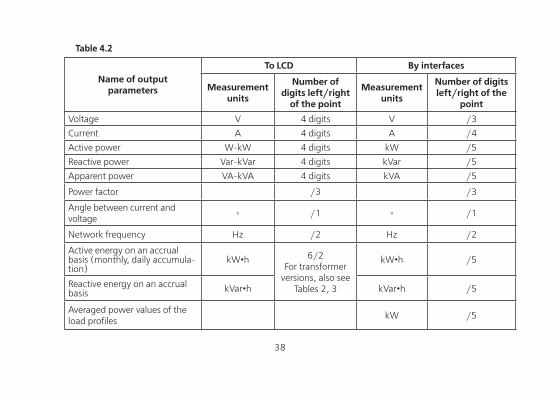
4.1.1 A complete list of output formats of measured, calculated and accumulated parameters is given in Table 4.2.
38
Table 4.2
Name of outputparameters
To LCD By interfaces
Measurementunits
Number of digits left/right
of the point
Measurementunits
Number of digits left/right of the
point
Voltage V 4 digits V /3
Current А 4 digits А /4
Active power W-kW 4 digits kW /5
Reactive power Var-kVar 4 digits kVar /5
Apparent power VA-kVA 4 digits kVA /5
Power factor /3 /3
Angle between current and voltage
◦ /1 ◦ /1
Network frequency Hz /2 Hz /2
Active energy on an accrual basis (monthly, daily accumula-tion)
kW•h 6/2For transformer
versions, also seeTables 2, 3
kW•h /5
Reactive energy on an accrual basis kVar•h kVar•h /5
Averaged power values of the load profiles
kW /5
38 39
The measurement units of the displayed energy/power values are indicated respectively as «kW•h» «kVAr•h», «MW•h» «MVAr•h» or «MkW•h» «MkVAr•h», respectively, and characterize the type of indicated energy, respectively: active and reactive.
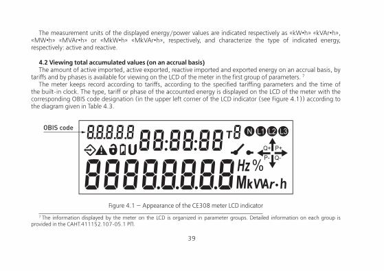
4.2 Viewing total accumulated values (on an accrual basis)The amount of active imported, active exported, reactive imported and exported energy on an accrual basis, by
tariffs and by phases is available for viewing on the LCD of the meter in the first group of parameters. 7
The meter keeps record according to tariffs, according to the specified tariffing parameters and the time of the built-in clock. The type, tariff or phase of the accounted energy is displayed on the LCD of the meter with the corresponding OBIS code designation (in the upper left corner of the LCD indicator (see Figure 4.1)) according to the diagram given in Table 4.3.
OBIS code
Figure 4.1 — Appearance of the CE308 meter LCD indicator 7 The information displayed by the meter on the LCD is organized in parameter groups. Detailed information on each group is
provided in the САНТ.411152.107-05.1 РП.
40
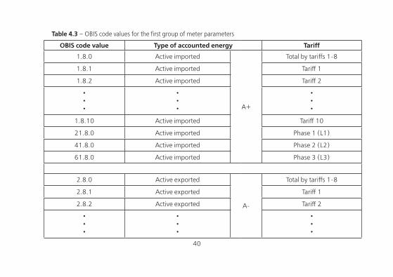
Table 4.3 – OBIS code values for the first group of meter parameters
OBIS code value Type of accounted energy Tariff
1.8.0 Active imported
A+
Total by tariffs 1-8
1.8.1 Active imported Tariff 1
1.8.2 Active imported Tariff 2
•••
•••
•••
1.8.10 Active imported Tariff 10
21.8.0 Active imported Phase 1 (L1)
41.8.0 Active imported Phase 2 (L2)
61.8.0 Active imported Phase 3 (L3)
2.8.0 Active exported
A-
Total by tariffs 1-8
2.8.1 Active exported Tariff 1
2.8.2 Active exported Tariff 2
•••
•••
•••
40 41
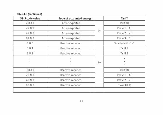
OBIS code value Type of accounted energy Tariff
2.8.10 Active exported
A-
Tariff 10
22.8.0 Active exported Phase 1 (L1)
42.8.0 Active exported Phase 2 (L2)
62.8.0 Active exported Phase 3 (L3)
3.8.0 Reactive imported
R+
Total by tariffs 1-8
3.8.1 Reactive imported Tariff 1
3.8.2 Reactive imported Tariff 2
•••
•••
•••
3.8.10 Reactive imported Tariff 10
23.8.0 Reactive imported Phase 1 (L1)
43.8.0 Reactive imported Phase 2 (L2)
63.8.0 Reactive imported Phase 3 (L3)
Table 4.3 (continued)
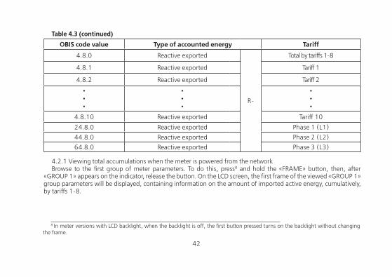
42
OBIS code value Type of accounted energy Tariff
4.8.0 Reactive exported
R-
Total by tariffs 1-8
4.8.1 Reactive exported Tariff 1
4.8.2 Reactive exported Tariff 2
•••
•••
•••
4.8.10 Reactive exported Tariff 10
24.8.0 Reactive exported Phase 1 (L1)
44.8.0 Reactive exported Phase 2 (L2)
64.8.0 Reactive exported Phase 3 (L3)
4.2.1 Viewing total accumulations when the meter is powered from the networkBrowse to the first group of meter parameters. To do this, press8 and hold the «FRAME» button, then, after
«GROUP 1» appears on the indicator, release the button. On the LCD screen, the first frame of the viewed «GROUP 1» group parameters will be displayed, containing information on the amount of imported active energy, cumulatively, by tariffs 1-8.
Table 4.3 (continued)
8 In meter versions with LCD backlight, when the backlight is off, the first button pressed turns on the backlight without changing
the frame.

42 43
By briefly pressing the «FRAME» button, select the type of metered energy:
«A+» → «A-» → «R+» → «R-»By briefly pressing the «VIEW» button, select a tariff:
«Total (by tariffs 1-8)» → «Tariff 1» → «Tariff 2» → … …→ «Tariff 10» → «Phase 1 (L1)» → «Phase 2 (L2)» → «Phase 3 (L3)»
Figure 4.2 shows the value («00089.38 kW*h») of the active imported energy on an accrual basis for the fifth tariff (the OBIS code value is «1.8.5»). At the present moment:
• the active tariff is 5 («Т5»);• the current time is «09h08m06s»;• the reactive power direction is «Q+», active power direction is «P-»;• all three phases are connected («L1, L2, L3»).
Figure 4.2
44
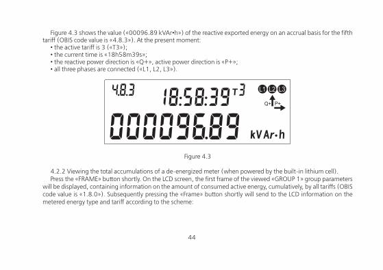
Figure 4.3 shows the value («00096.89 kVAr•h») of the reactive exported energy on an accrual basis for the fifth tariff (OBIS code value is «4.8.3»). At the present moment:
• the active tariff is 3 («Т3»);• the current time is «18h58m39s»;• the reactive power direction is «Q+», active power direction is «P+»;• all three phases are connected («L1, L2, L3»).
Figure 4.3
4.2.2 Viewing the total accumulations of a de-energized meter (when powered by the built-in lithium cell).Press the «FRAME» button shortly. On the LCD screen, the first frame of the viewed «GROUP 1» group parameters
will be displayed, containing information on the amount of consumed active energy, cumulatively, by all tariffs (OBIS code value is «1.8.0»). Subsequently pressing the «Frame» button shortly will send to the LCD information on the metered energy type and tariff according to the scheme:
44 45
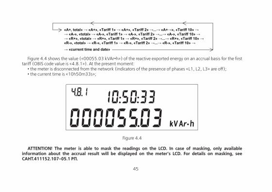
«А+, total» → «А+», «Tariff 1» → «А+», «Tariff 2» →...→ «А+→», «Tariff 10» →→ «А-», «total» → «А-», «Tariff 1» → «А-», «Tariff 2» →...→ «А-», «Tariff 10» →→ «R+», «total» → «R+», «Tariff 1» → «R+», «Tariff 2» →...→ «R+», «Tariff 10» → «R-», «total» → «R-», «Tariff 1» → «R-», «Tariff 2» →...→ «R-», «Tariff 10» →→ «current time and date»
Figure 4.4 shows the value («00055.03 kVAr•h») of the reactive exported energy on an accrual basis for the first tariff (OBIS code value is «4.8.1»). At the present moment:
• the meter is disconnected from the network (indicators of the presence of phases «L1, L2, L3» are off);• the current time is «10h50m33s»;
Figure 4.4
ATTENTION! The meter is able to mask the readings on the LCD. In case of masking, only available information about the accrual result will be displayed on the meter’s LCD. For details on masking, see САНТ.411152.107-05.1 РП.
46
5 METER VERIFICATION
5.1 The verification is carried out according to «CE308 multifunctional three-phase electric meters. САНТ.411152.107 Д1 verification method», when released from production, after mid-term repair or periodically once every 169 years.
6 MAINTENANCE AND SEALING
6.1 Maintenance of the meter at the installation sites consists in systematic monitoring of its operation and eliminating meter errors and malfunctions.
6.2 ATTENTION! IN CASE OF LCD FAILURE, THE INFORMATION IS STORED FOR 30 YEARS. YOU CAN READ THE INFORMATION VIA THE METER INTERFACE BY CONNECTING THE METER TO THE POWER NETWORK.
6.3 The terminal cover, as well as the ACCESS button, are sealed by the company commissioning the meter.The meter case is sealed with two seals: by the verification officer and by the QC department.The terminal cover is sealed with one or two seals at the discretion of the company commissioning the meter.The ACCESS button is sealed by closing the button cover and threading the wire through the hole in the cover and
the screw hole, hanging a seal and crimping it.
9 For meters supplied to the Republic of Kazakhstan, the interval between verifications is 8 years.
46 47
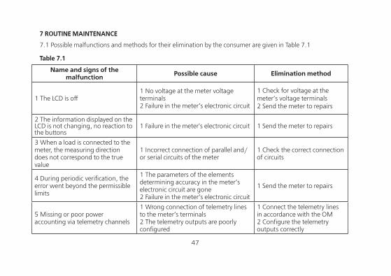
7 ROUTINE MAINTENANCE
7.1 Possible malfunctions and methods for their elimination by the consumer are given in Table 7.1
Table 7.1
Name and signs of the malfunction Possible cause Elimination method
1 The LCD is off1 No voltage at the meter voltage terminals2 Failure in the meter’s electronic circuit
1 Check for voltage at the meter’s voltage terminals2 Send the meter to repairs
2 The information displayed on the LCD is not changing, no reaction to the buttons
1 Failure in the meter's electronic circuit 1 Send the meter to repairs
3 When a load is connected to the meter, the measuring direction does not correspond to the true value
1 Incorrect connection of parallel and/or serial circuits of the meter
1 Check the correct connection of circuits
4 During periodic verification, the error went beyond the permissible limits
1 The parameters of the elements determining accuracy in the meter’s electronic circuit are gone2 Failure in the meter’s electronic circuit
1 Send the meter to repairs
5 Missing or poor power accounting via telemetry channels
1 Wrong connection of telemetry lines to the meter’s terminals2 The telemetry outputs are poorly configured
1 Connect the telemetry lines in accordance with the OM2 Configure the telemetry outputs correctly
48
8 STORAGE AND TRANSPORTATION CONDITIONS
8.1 Meters must be stored in the manufacturer’s packaging at an ambient temperature of 5 to 40 °C and a relative humidity of 80% at a temperature of 25 °C.
8.2 Meters are transported in closed vehicles of any kind.Limiting transportation conditions:– ambient air temperature: from minus 40 to plus 70 °С – relative humidity: 98% at a temperature of 35 °С.– atmospheric pressure from 70 to 106.7 kPa (537-800 mm Hg).– transportation bounce for 1 hour with an acceleration of 30 m/s2 with shocks rate of 80 to 120 per minute.
9 CONTAINERS AND PACKING
9.1 The meters, operational and shipping documentation are packed in accordance with the manufacturer’s drawings.
9.2 A meter prepared for packing is placed in a polyethylene bag according to GOST 12302-2013,put in consumer cardboard packaging T15EE GOST R 52901-2007.9.3 Operational documentation is in consumer packaging on top of the product. The consumer packaging is
covered with packing tape.9.4 The meters, packed in consumer packaging, are placed in a shipping container, which is a cardboard box
made according to the manufacturer’s drawings.9.5 The shipping document is enclosed in the box, including a packing list containing the following information:– name and symbol of the meters, their quantity;– packing date;– signature of the person responsible for packing;– stamp of the QC department.The box is sealed.
48 49
9.6 Overall dimensions of the package, net weight, gross weight meet the requirements of the manufacturer’s design documentation.
10 LABELING
10.1 Information applied to the front panel of the meter by offset printing or in another way not degrading the quality:
– meter type designation — CE308;– accuracy class according to IEC 62053-21:2003 (IEC 62053-22:2003), IEC 62053-23:2003;– meter constant in accordance with Table 2.2;– a bar code including the year of manufacture, the number of the meter and other additional information;– the nominal secondary current of the transformer, to which the meter can be connected, or the base and max.
current;– nominal voltage;– frequency 50 Hz;– the number of phases and the number of wires in the circuit for which the counter is intended, as a graphic
symbol in accordance with GOST 25372-95;– trademark of the manufacturing enterprise – ENERGOMERA;– IEC 62052-11:2003, IEC 62053-21:2003(IEC 62053-22:2003), IEC 62053-23:2003.– measuring instruments approval type sign image;– the image of the common EAC circulation mark when receiving the certificate;– a double square sign for protection class II meters placed into insulating bodies;– insulation testing voltage (C2 symbol as per GOST 23217-78);– the symbol according to GOST 25372-95 for a meter with measuring transformers;– inscription – RUSSIA;– interface type in accordance with the structure of the meter designation given in clause 2.2.1;
50
– labeling of controls «FRAME», «VIEW», «ACCESS».There is a place on the cover of the meter’s clamping block for applying the transformation ratio of the measuring
current and voltage transformers designed to work in conjunction with the meters, the transformer multiplier and number.
An «Attention» sign ( ) in accordance with GOST 23217-78.
50 51
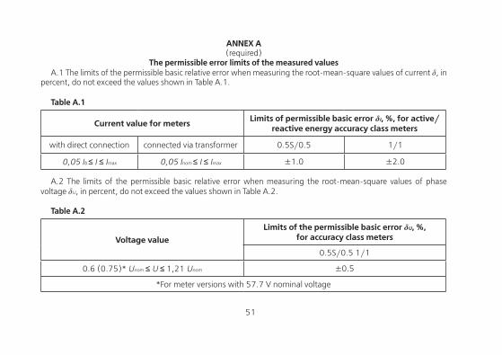
ANNEX A(required)
The permissible error limits of the measured valuesA.1 The limits of the permissible basic relative error when measuring the root-mean-square values of current δ, in
percent, do not exceed the values shown in Table A.1.
Table А.1
Current value for meters Limits of permissible basic error δI, %, for active/reactive energy accuracy class meters
with direct connection connected via transformer 0.5S/0.5 1/1
0,05 Ib ≤ I ≤ Imax 0,05 Inom ≤ I ≤ Imax ±1.0 ±2.0
A.2 The limits of the permissible basic relative error when measuring the root-mean-square values of phase voltage δU, in percent, do not exceed the values shown in Table A.2.
Table А.2
Voltage value
Limits of the permissible basic error δU, %, for accuracy class meters
0.5S/0.5 1/1
0.6 (0.75)* Unom ≤ U ≤ 1,21 Unom ±0.5
*For meter versions with 57.7 V nominal voltage
52
ANNEX B(required)
General appearance of a CE308 S31 meter
52 53
General appearance of a CE308 S34 meter
54
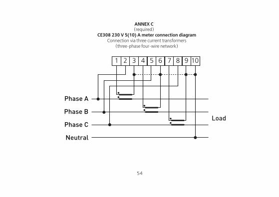
ANNEX C(required)
CE308 230 V 5(10) А meter connection diagramConnection via three current transformers
(three-phase four-wire network)
1 2 4 5 6 7 8 9 103
Phase А
Phase В
Phase С
Neutral
Load
54 55
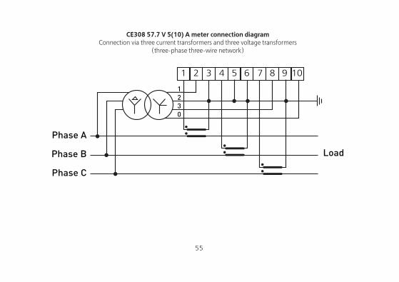
CE308 57.7 V 5(10) А meter connection diagramConnection via three current transformers and three voltage transformers
(three-phase three-wire network)
1 2 4 5 6 7 8 9 103
Phase А
Phase В
Phase С
Load
1230
56
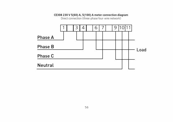
CE308 230 V 5(60) А, 5(100) А meter connection diagramDirect connection (three-phase four-wire network)
Load
1 4 6 7 9 10 113
Phase А
Phase В
Phase С
Neutral

56


![Untitled-4 [] · Standard lamineret (8 meter / *4 meter) Neon lamineret - 5 meter Mat lamineret - 8 meter / **5 meter) Metallic lamineret - 8 meter Ulamineret - 8 meter Fleksibel](https://img.pdfslide.tips/doc/110x75/5f3a768af7b8e86a6437cff7/untitled-4-standard-lamineret-8-meter-4-meter-neon-lamineret-5-meter.jpg)