Embed Size (px)
Citation preview
ELECTRICAL DISCHARGES IN GASES AND PRINCIPLES OF ION NITRIDING
First Edition
Edward Rolinski
Advanced Heat Treat Corp. 1625 Rose Street, Monroe, MI 48162
Edward Rolinski Page 1 1/7/2009
Table of Contents Page
1. Introduction……………………………………………………………………3 2. Glow Discharge………………………………………………………………..3 2.1. Evolution of a glow discharge, starting potential and breakdown….…… 10 2.2. The cathode fall region………………………..……………………………..10 2.2.1. The normal cathode fall of potential ……………………………………..12 2.2.2. The abnormal cathode fall of potential…………………………………...12 2.3. The hollow cathode discharge……………………………………………….15 2.4. Arc discharge…………………………………………………………………18 3. Mechanism of ion nitriding…………………………………………………….21 4. References………………………………………………………………………23
Edward Rolinski Page 2 1/7/2009
Electrical Discharge in Gases and Principles of Ion Nitriding
1. Introduction Ion nitriding uses a dc or pulse dc glow discharge and therefore a good knowledge of the basic phenomena accruing in the plasmas, is important in understanding this process. Principally, the entire process deals with the cathode-anode relationship in a medium vacuum of approximately 0.4-13 mbar (0.03-10 torr). The ionized gas in between these two electrodes is very often called “cold plasma”. In cold plasmas electrons have much higher energy than ions, while in thermal plasmas those energies are equal. The cathode in ion nitriding is a treated part while the anode is the vacuum vessel itself. The active nitrogen species needed for nitriding reaction as well as the heat required for rising and maintaining processing temperature in the so-called “cold wall” ion nitriding, is generated entirely by the plasma. In “hot wall” ion nitriding, the auxiliary resistance heaters also supply the heat and therefore the portion of the heat supplied by plasma is reduced. Glow discharge has a tendency to become unstable under certain conditions and to form an arc discharge. Arc is a high-density localized discharge causing serious problems in damaging the surface of the workpiece and complicating control of the plasma. It has to be controlled by special arc detectors. In the past, the application of ion nitriding technology was limited by insufficient progress in the electronic and computer industries. Hollow cathode effect is a form of localized, but stable discharge occurring with a specific cathode (load) shape or configuration. This is also potentially dangerous phenomenon leading to a localized uncontrollable raise of temperature. It can be avoided with a proper control of plasma and/or appropriate configuring of the load. Sputtering is another important phenomena cased by the glow discharge. This is a process of the removal of atoms from the cathode by the high-energy ions or neutrals bombarding its surface. Some of the sputtered atoms react with the active plasma species and in the form of nitrides are deposited on the vessel walls or come back to the cathode. This process is called reactive sputtering. Sputtering phenomena is especially important in nitriding stainless steels but this is not the leading process in mechanism of nitriding. Instead, formation of the active nitrogen species by glow discharge is the critical precursor step before adsorption and diffusion of nitrogen atoms can occur. 2. Glow Discharge (based on Ref.1 and 2) A glow discharge is conveniently described as a discharge in which the cathode emits electrons under bombardment of particles and light quanta from the gas. The cathode field is essentially determined by positive space charges. Thermal effects are either absent or at least not a necessary condition for maintaining the discharge. Electrons produced at the cathode surface by positive ion bombardment maintain the discharge. In the Aston dark space there is accumulation of these electrons, which gain energy through the Crookes dark space. The cathode glow results from the decay of excitation energy of the positive ions on neutralization. When the electrons gain sufficient energy in the Crookes dark space (also called cathode fall, cathode dark space, or Hittorf dark space) to produce inelastic collisions, the excitation of the gas produces the negative glow. The
Edward Rolinski Page 3 1/7/2009
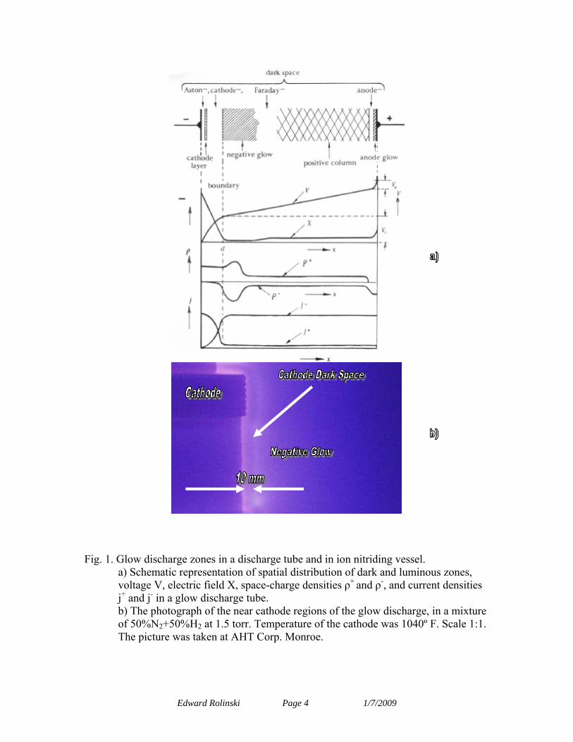
Fig. 1. Glow discharge zones in a discharge tube and in ion nitriding vessel.
a) Schematic representation of spatial distribution of dark and luminous zones, voltage V, electric field X, space-charge densities ρ+ and ρ-, and current densities j+ and j- in a glow discharge tube. b) The photograph of the near cathode regions of the glow discharge, in a mixture of 50%N2+50%H2 at 1.5 torr. Temperature of the cathode was 1040º F. Scale 1:1. The picture was taken at AHT Corp. Monroe.
Edward Rolinski Page 4 1/7/2009
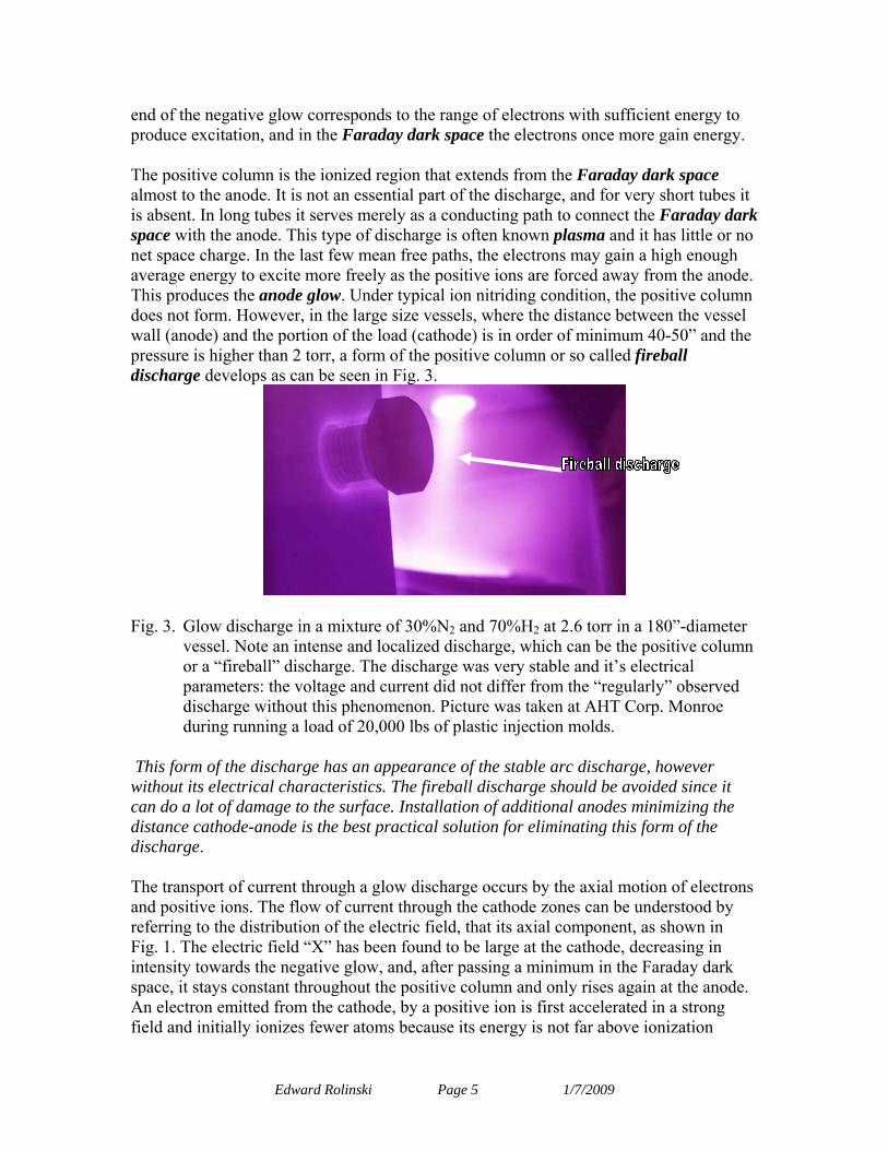
end of the negative glow corresponds to the range of electrons with sufficient energy to produce excitation, and in the Faraday dark space the electrons once more gain energy. The positive column is the ionized region that extends from the Faraday dark space almost to the anode. It is not an essential part of the discharge, and for very short tubes it is absent. In long tubes it serves merely as a conducting path to connect the Faraday dark space with the anode. This type of discharge is often known plasma and it has little or no net space charge. In the last few mean free paths, the electrons may gain a high enough average energy to excite more freely as the positive ions are forced away from the anode. This produces the anode glow. Under typical ion nitriding condition, the positive column does not form. However, in the large size vessels, where the distance between the vessel wall (anode) and the portion of the load (cathode) is in order of minimum 40-50” and the pressure is higher than 2 torr, a form of the positive column or so called fireball discharge develops as can be seen in Fig. 3.
Fig. 3. Glow discharge in a mixture of 30%N2 and 70%H2 at 2.6 torr in a 180”-diameter
vessel. Note an intense and localized discharge, which can be the positive column or a “fireball” discharge. The discharge was very stable and it’s electrical parameters: the voltage and current did not differ from the “regularly” observed discharge without this phenomenon. Picture was taken at AHT Corp. Monroe during running a load of 20,000 lbs of plastic injection molds.
This form of the discharge has an appearance of the stable arc discharge, however without its electrical characteristics. The fireball discharge should be avoided since it can do a lot of damage to the surface. Installation of additional anodes minimizing the distance cathode-anode is the best practical solution for eliminating this form of the discharge. The transport of current through a glow discharge occurs by the axial motion of electrons and positive ions. The flow of current through the cathode zones can be understood by referring to the distribution of the electric field, that its axial component, as shown in Fig. 1. The electric field “X” has been found to be large at the cathode, decreasing in intensity towards the negative glow, and, after passing a minimum in the Faraday dark space, it stays constant throughout the positive column and only rises again at the anode. An electron emitted from the cathode, by a positive ion is first accelerated in a strong field and initially ionizes fewer atoms because its energy is not far above ionization
Edward Rolinski Page 5 1/7/2009
potential. However, further from the cathode the electron ionizes more efficiently and strong electron multiplication will take place. Near the boundary between the cathode space and the negative glow the electric field has become very weak, and thus only the fast electrons which have not lost energy by inelastic collisions will be able to ionize in that region. Also, a large number of electrons will cross the boundary and enter the negative glow. Due to multiplication the number of electrons able to ionize has increased between the cathode and the glow boundary, and large number of positive ions has been formed representing a strong positive space charge. These positive ions will move unexcited atoms (charge transfer), and radiation will fall on the cathode with the result that secondary electrons are emitted from it. In order to have a steady state, each electron, which is emitted by the cathode, must produce sufficient ionizations and excitations to affect the release of one further electron from the cathode. Fig. 1 also explains the distribution of the emitted light. An electron usually starts at the cathode with a very small initial speed of order of 1 eV. It is not able to excite gas molecules unless its energy has reached at least excitation potential, which will not occur within the first few V (5-10 eV) from the cathode corresponding to Aston’s dark space. The cathode layer is the region within which the electron acquires an energy cor-responding to the maxima of the excitation functions. Since the maxima for different spectral lines lie at different energies it follows that the lines should be observed in such order that the lowest energy should lie near cathode. This is actually the case. At higher cathode fall Aston’s dark space and cathode layer are replaced by the cathode glow. At larger distances from the cathode most (but not all) electrons have speeds which lie far beyond the maximum of the excitation functions and thus little visible light is emitted from the cathode dark space. At the negative glow boundary the number of slow electrons has become very large and their speed decreases with increasing distance from the cathode; thus in general these spectral lines appear in the reverse order as one approaches the glow. The electrons entering the glow consist of at least two groups: those, which were produced at or near cathode and are fast, have not suffered loses by collisions in the dark space. The other groups of electrons, which have made many inelastic collisions, have been created in the dark space and are therefore slow. Since the slow electrons have energies below the ionization maximum but above or at excitation maximum, they experience many exciting collisions and produce the negative glow. Afterwards their energy becomes so small that recombination with positive ions take place. This process is likely to occur in and beyond the negative glow since the concentration of ions and electrons in that region is large and the electric field low. The emission light due to recombination is, however, in general small. With increasing distance from the boundary fewer fast electrons are found and less visible light is emitted. The electric field raises slowly, the probability of recombination decreases, and the Faraday dark space develops. Theory of the positive column formation is well known since it was required for the development of the neon tubes. Even if the positive column does not appear to be present in the typical geometrical arrangements of the electrodes in the ion nitriding process, it may still occur under very specific condition described previously and which should be avoided.
Edward Rolinski Page 6 1/7/2009
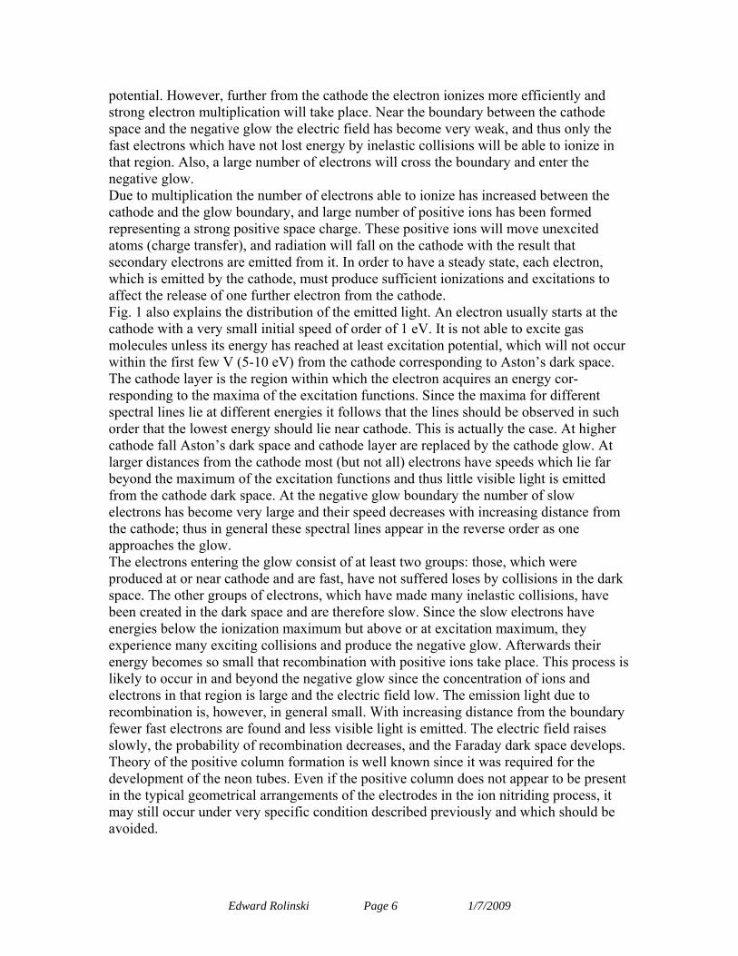
To minimize the risk of the positive column formation, supporting anodes are frequently used in large size nitriders to enhance glow discharge when the distance between various portions of the load (cathode) to the vessel wall (anode) is significant as it was discussed previously in this chapter. Even if anodic glow discharge is usually very weak on the
Fig. 4. Anodic glow discharge in a mixture of 50% N2+2%CH4+40% H2 at a pressure of
1.5 torr in a 180-inch diameter vessel. Temperature of the central anode was 1140º F and temperature of the load (cathode) was 940º F. Picture was taken at AHT Corp. Monroe during running a load of 25,000 lbs of stamping dies.
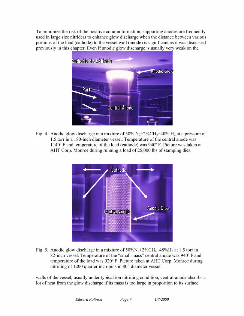
Fig. 5. Anodic glow discharge in a mixture of 50%N2+2%CH4+48%H2 at 1.5 torr in
82-inch vessel. Temperature of the “small-mass” central anode was 940º F and temperature of the load was 920º F. Picture taken at AHT Corp. Monroe during nitriding of 1200 quarter inch-pins in 80” diameter vessel.
walls of the vessel, usually under typical ion nitriding condition, central-anode absorbs a lot of heat from the glow discharge if its mass is too large in proportion to its surface
Edward Rolinski Page 7 1/7/2009
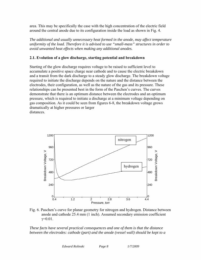
area. This may be specifically the case with the high concentration of the electric field around the central anode due to its configuration inside the load as shown in Fig. 4. The additional and usually unnecessary heat formed in the anode, may affect temperature uniformity of the load. Therefore it is advised to use “small-mass” structures in order to avoid unwanted heat effects when making any additional anodes. 2.1. Evolution of a glow discharge, starting potential and breakdown Starting of the glow discharge requires voltage to be raised to sufficient level to accumulate a positive space charge near cathode and to cause the electric breakdown and a transit from the dark discharge to a steady glow discharge. The breakdown voltage required to initiate the discharge depends on the nature and the distance between the electrodes, their configuration, as well as the nature of the gas and its pressure. These relationships can be presented best in the form of the Paschen’s curves. The curves demonstrate that there is an optimum distance between the electrodes and an optimum pressure, which is required to initiate a discharge at a minimum voltage depending on gas composition. As it could be seen from figures 6-8, the breakdown voltage grows dramatically at higher pressures or larger distances.
0.4 1.2 2 2.8 3.6 4.4Pressure, torr
0
240
480
720
960
1200
Bre
akdo
wn
Vol
tage
, V
0
240
480
720
960
1200
Bre
akdo
wn
Vol
tage
, V
nitrogen
hydrogen
Fig. 6. Paschen’s curve for planar geometry for nitrogen and hydrogen. Distance between anode and cathode 25.4 mm (1 inch). Assumed secondary emission coefficient γ=0.01.
These facts have several practical consequences and one of them is that the distance between the electrodes: cathode (part) and the anode (vessel wall) should be kept to a
Edward Rolinski Page 8 1/7/2009
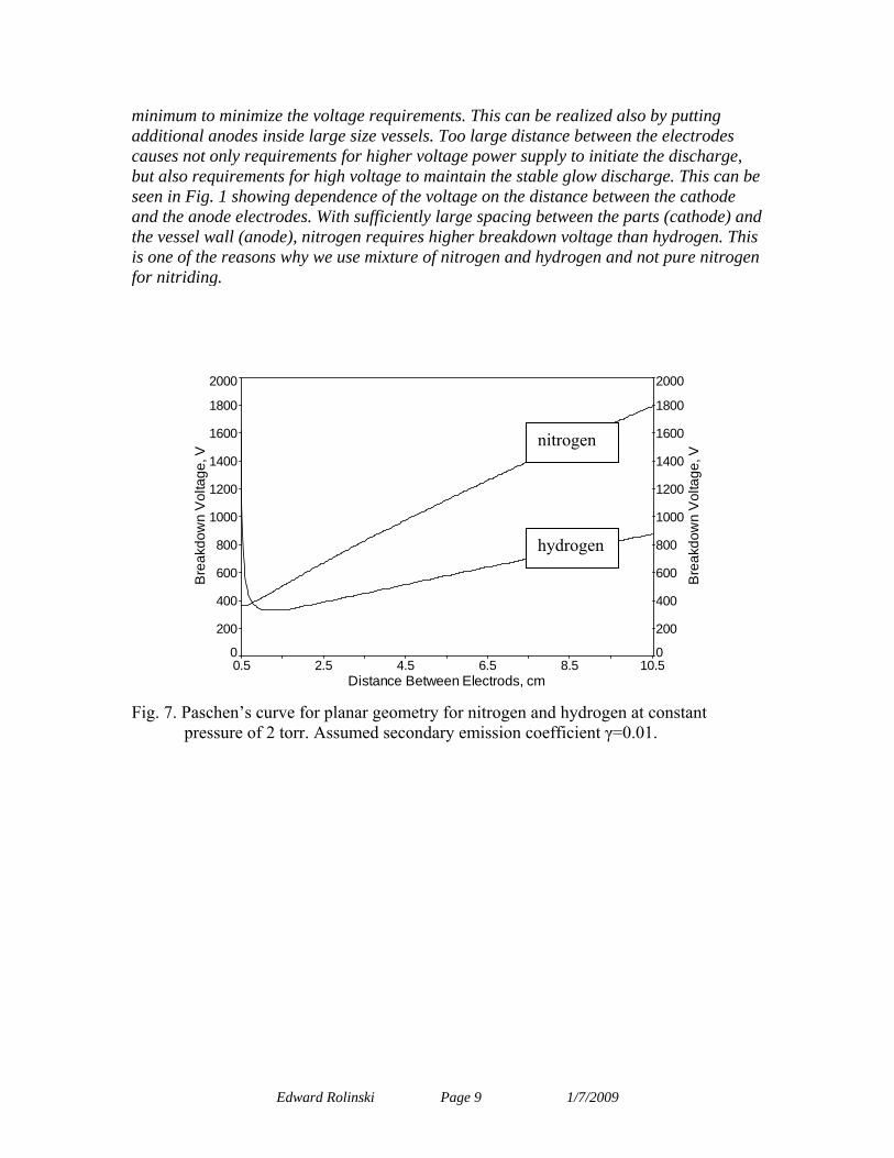
minimum to minimize the voltage requirements. This can be realized also by putting additional anodes inside large size vessels. Too large distance between the electrodes causes not only requirements for higher voltage power supply to initiate the discharge, but also requirements for high voltage to maintain the stable glow discharge. This can be seen in Fig. 1 showing dependence of the voltage on the distance between the cathode and the anode electrodes. With sufficiently large spacing between the parts (cathode) and the vessel wall (anode), nitrogen requires higher breakdown voltage than hydrogen. This is one of the reasons why we use mixture of nitrogen and hydrogen and not pure nitrogen for nitriding.
0.5 2.5 4.5 6.5 8.5 10.5Distance Between Electrods, cm
0
200
400
600
800
1000
1200
1400
1600
1800
2000
Bre
akdo
wn
Vol
tage
, V
0
200
400
600
800
1000
1200
1400
1600
1800
2000
Bre
akdo
wn
Vol
tage
, VFig. 7. Paschen’s curve for planar geometry for nitrogen and hydrogen at constant
nitrogen
hydrogen
pressure of 2 torr. Assumed secondary emission coefficient γ=0.01.
Edward Rolinski Page 9 1/7/2009
0.02 0.216 0.412 0.608 0.804 1Pressure, torr
0
200
400
600
800
1000
1200
1400
1600
1800
2000B
reak
dow
n V
olta
ge, V
0
200
400
600
800
1000
1200
1400
1600
1800
2000
Bre
akdo
wn
Vol
tage
, V
nitrogen
hydrogen
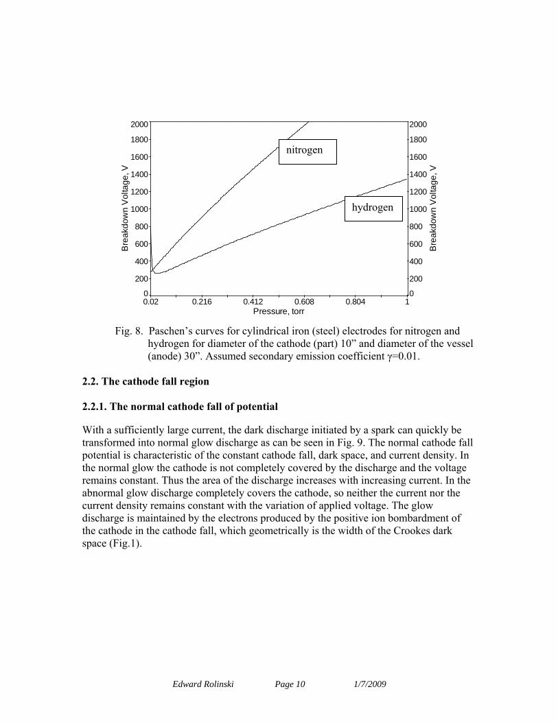
Fig. 8. Paschen’s curves for cylindrical iron (steel) electrodes for nitrogen and hydrogen for diameter of the cathode (part) 10” and diameter of the vessel (anode) 30”. Assumed secondary emission coefficient γ=0.01.
2.2. The cathode fall region 2.2.1. The normal cathode fall of potential
With a sufficiently large current, the dark discharge initiated by a spark can quickly be transformed into normal glow discharge as can be seen in Fig. 9. The normal cathode fall potential is characteristic of the constant cathode fall, dark space, and current density. In the normal glow the cathode is not completely covered by the discharge and the voltage remains constant. Thus the area of the discharge increases with increasing current. In the abnormal glow discharge completely covers the cathode, so neither the current nor the current density remains constant with the variation of applied voltage. The glow discharge is maintained by the electrons produced by the positive ion bombardment of the cathode in the cathode fall, which geometrically is the width of the Crookes dark space (Fig.1).
Edward Rolinski Page 10 1/7/2009
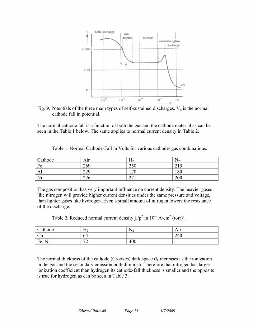
Fig. 9. Potentials of the three main types of self-sustained discharges. Vn is the normal
cathode fall in potential.
The normal cathode fall is a function of both the gas and the cathode material as can be seen in the Table 1 below. The same applies to normal current density in Table 2.
Table 1. Normal Cathode-Fall in Volts for various cathode/ gas combinations.
Cathode Air H2 N2 Fe 269 250 215 Al 229 170 180 Ni 226 271 200
The gas composition has very important influence on current density. The heavier gases like nitrogen will provide higher current densities under the same pressure and voltage, than lighter gases like hydrogen. Even a small amount of nitrogen lowers the resistance of the discharge.
Table 2. Reduced normal current density jn/p2 in 10-6 A/cm2 (torr)2. Cathode H2 N2 Air Cu 64 - 240 Fe, Ni 72 400 - The normal thickness of the cathode (Crookes) dark space dn increases as the ionization in the gas and the secondary emission both diminish. Therefore that nitrogen has larger ionization coefficient than hydrogen its cathode-fall thickness is smaller and the opposite is true for hydrogen as can be seen in Table 3.
Edward Rolinski Page 11 1/7/2009
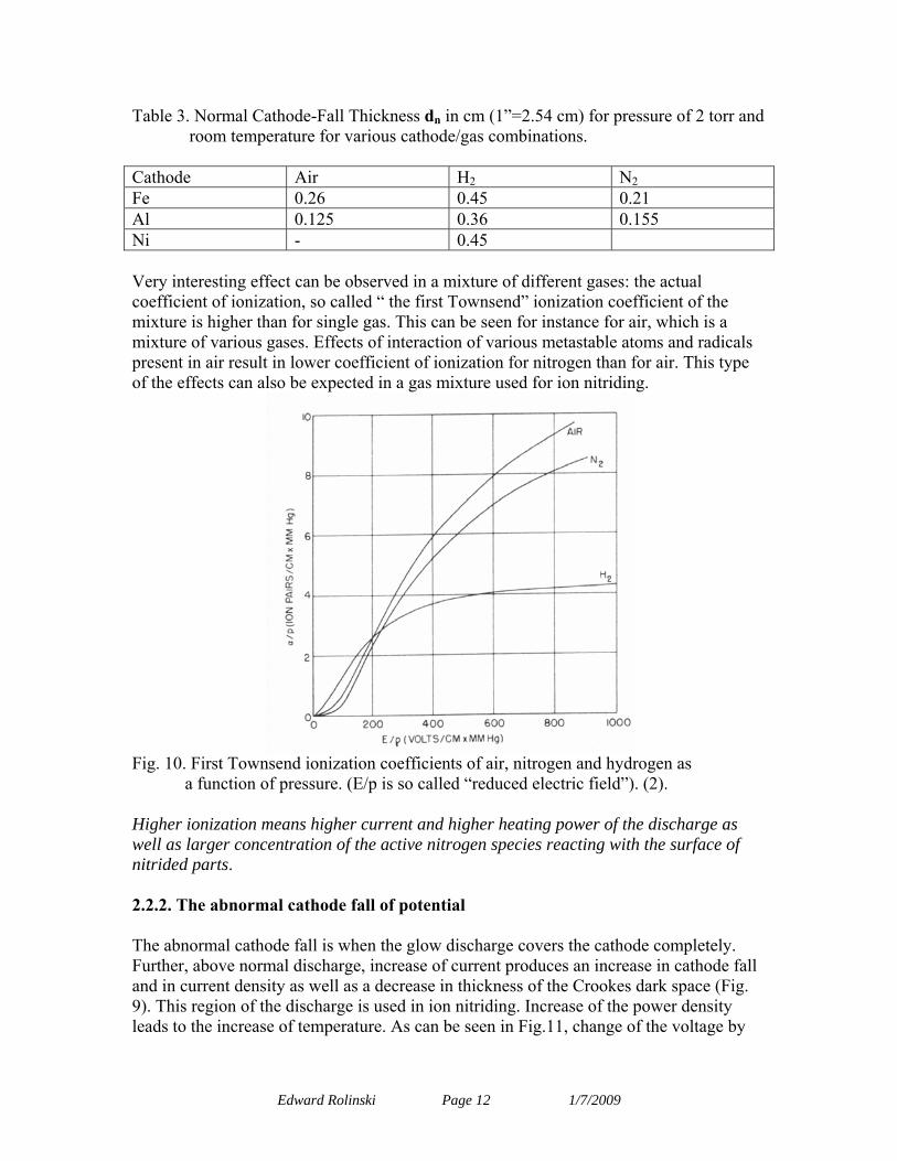
Table 3. Normal Cathode-Fall Thickness dn in cm (1”=2.54 cm) for pressure of 2 torr and room temperature for various cathode/gas combinations.
Cathode Air H2 N2 Fe 0.26 0.45 0.21 Al 0.125 0.36 0.155 Ni - 0.45 Very interesting effect can be observed in a mixture of different gases: the actual coefficient of ionization, so called “ the first Townsend” ionization coefficient of the mixture is higher than for single gas. This can be seen for instance for air, which is a mixture of various gases. Effects of interaction of various metastable atoms and radicals present in air result in lower coefficient of ionization for nitrogen than for air. This type of the effects can also be expected in a gas mixture used for ion nitriding.
Fig. 10. First Townsend ionization coefficients of air, nitrogen and hydrogen as
a function of pressure. (E/p is so called “reduced electric field”). (2). Higher ionization means higher current and higher heating power of the discharge as well as larger concentration of the active nitrogen species reacting with the surface of nitrided parts. 2.2.2. The abnormal cathode fall of potential The abnormal cathode fall is when the glow discharge covers the cathode completely. Further, above normal discharge, increase of current produces an increase in cathode fall and in current density as well as a decrease in thickness of the Crookes dark space (Fig. 9). This region of the discharge is used in ion nitriding. Increase of the power density leads to the increase of temperature. As can be seen in Fig.11, change of the voltage by
Edward Rolinski Page 12 1/7/2009
about one order of magnitude causes up to three orders in magnitude raise in current density. Increase of the current (power) density leads to increase of temperature to the range required for nitriding.
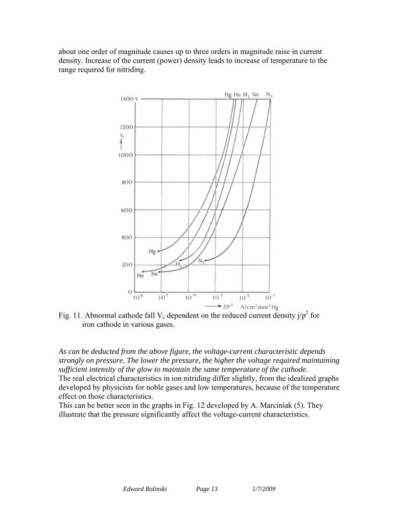
Fig. 11. Abnormal cathode fall Vc dependent on the reduced current density j/p2 for
iron cathode in various gases. As can be deducted from the above figure, the voltage-current characteristic depends strongly on pressure. The lower the pressure, the higher the voltage required maintaining sufficient intensity of the glow to maintain the same temperature of the cathode. The real electrical characteristics in ion nitriding differ slightly, from the idealized graphs developed by physicists for noble gases and low temperatures, because of the temperature effect on those characteristics. This can be better seen in the graphs in Fig. 12 developed by A. Marciniak (5). They illustrate that the pressure significantly affect the voltage-current characteristics.
Edward Rolinski Page 13 1/7/2009
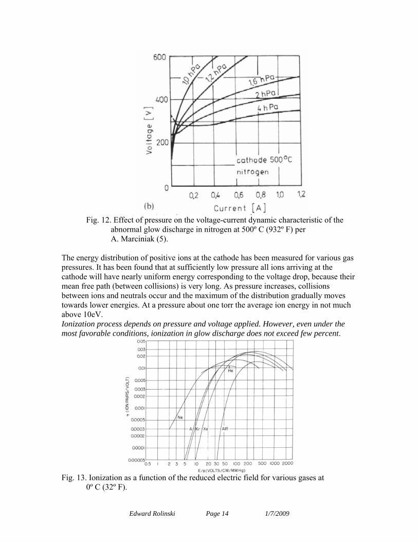
Fig. 12. Effect of pressure on the voltage-current dynamic characteristic of the
abnormal glow discharge in nitrogen at 500º C (932º F) per A. Marciniak (5).
The energy distribution of positive ions at the cathode has been measured for various gas pressures. It has been found that at sufficiently low pressure all ions arriving at the cathode will have nearly uniform energy corresponding to the voltage drop, because their mean free path (between collisions) is very long. As pressure increases, collisions between ions and neutrals occur and the maximum of the distribution gradually moves towards lower energies. At a pressure about one torr the average ion energy in not much above 10eV. Ionization process depends on pressure and voltage applied. However, even under the most favorable conditions, ionization in glow discharge does not exceed few percent.
Fig. 13. Ionization as a function of the reduced electric field for various gases at
0º C (32º F).
Edward Rolinski Page 14 1/7/2009
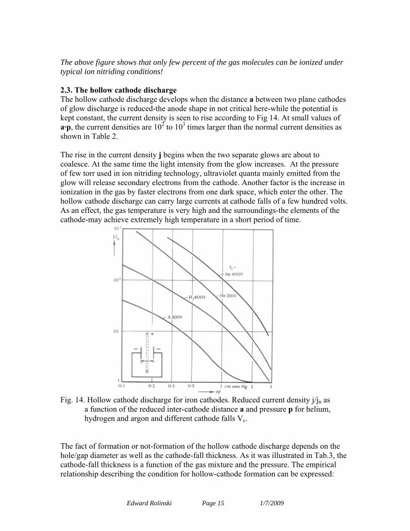
The above figure shows that only few percent of the gas molecules can be ionized under typical ion nitriding conditions! 2.3. The hollow cathode discharge The hollow cathode discharge develops when the distance a between two plane cathodes of glow discharge is reduced-the anode shape in not critical here-while the potential is kept constant, the current density is seen to rise according to Fig 14. At small values of a·p, the current densities are 102 to 103 times larger than the normal current densities as shown in Table 2. The rise in the current density j begins when the two separate glows are about to coalesce. At the same time the light intensity from the glow increases. At the pressure of few torr used in ion nitriding technology, ultraviolet quanta mainly emitted from the glow will release secondary electrons from the cathode. Another factor is the increase in ionization in the gas by faster electrons from one dark space, which enter the other. The hollow cathode discharge can carry large currents at cathode falls of a few hundred volts. As an effect, the gas temperature is very high and the surroundings-the elements of the cathode-may achieve extremely high temperature in a short period of time.
Fig. 14. Hollow cathode discharge for iron cathodes. Reduced current density j/jn as
a function of the reduced inter-cathode distance a and pressure p for helium, hydrogen and argon and different cathode falls Vc.
The fact of formation or not-formation of the hollow cathode discharge depends on the hole/gap diameter as well as the cathode-fall thickness. As it was illustrated in Tab.3, the cathode-fall thickness is a function of the gas mixture and the pressure. The empirical relationship describing the condition for hollow-cathode formation can be expressed:
Edward Rolinski Page 15 1/7/2009
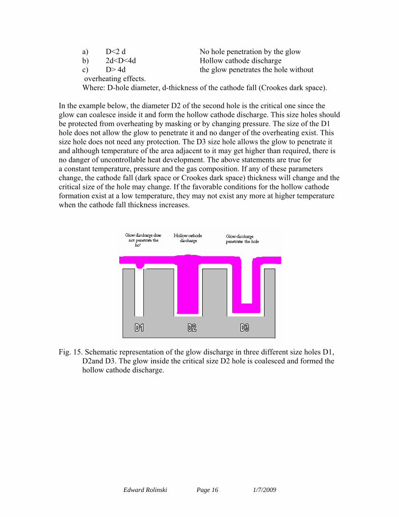
a) D<2 d No hole penetration by the glow b) 2d<D<4d Hollow cathode discharge c) D> 4d the glow penetrates the hole without overheating effects. Where: D-hole diameter, d-thickness of the cathode fall (Crookes dark space).
In the example below, the diameter D2 of the second hole is the critical one since the glow can coalesce inside it and form the hollow cathode discharge. This size holes should be protected from overheating by masking or by changing pressure. The size of the D1 hole does not allow the glow to penetrate it and no danger of the overheating exist. This size hole does not need any protection. The D3 size hole allows the glow to penetrate it and although temperature of the area adjacent to it may get higher than required, there is no danger of uncontrollable heat development. The above statements are true for a constant temperature, pressure and the gas composition. If any of these parameters change, the cathode fall (dark space or Crookes dark space) thickness will change and the critical size of the hole may change. If the favorable conditions for the hollow cathode formation exist at a low temperature, they may not exist any more at higher temperature when the cathode fall thickness increases.
Fig. 15. Schematic representation of the glow discharge in three different size holes D1,
D2and D3. The glow inside the critical size D2 hole is coalesced and formed the hollow cathode discharge.
Edward Rolinski Page 16 1/7/2009
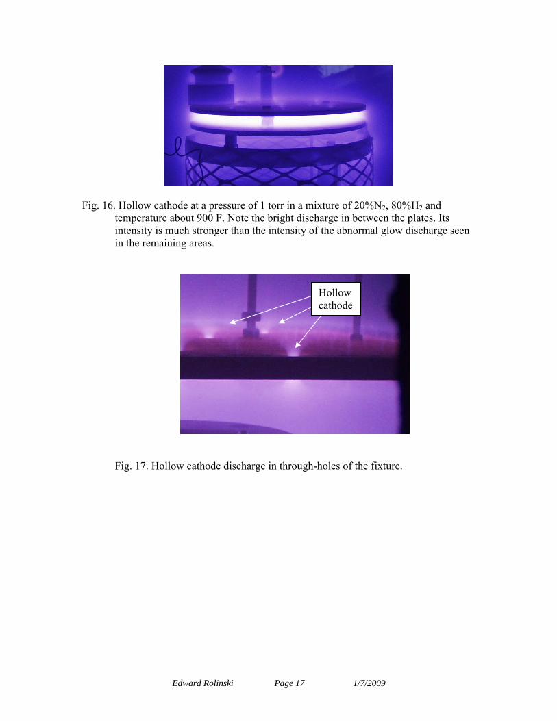
Fig. 16. Hollow cathode at a pressure of 1 torr in a mixture of 20%N2, 80%H2 and
temperature about 900 F. Note the bright discharge in between the plates. Its intensity is much stronger than the intensity of the abnormal glow discharge seen in the remaining areas.
Hollow cathode
Fig. 17. Hollow cathode discharge in through-holes of the fixture.
Edward Rolinski Page 17 1/7/2009
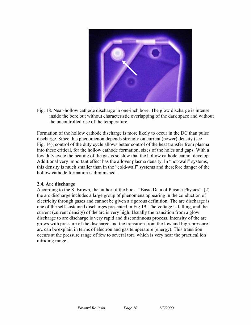
Fig. 18. Near-hollow cathode discharge in one-inch bore. The glow discharge is intense inside the bore but without characteristic overlapping of the dark space and without the uncontrolled rise of the temperature.
Formation of the hollow cathode discharge is more likely to occur in the DC than pulse discharge. Since this phenomenon depends strongly on current (power) density (see Fig. 14), control of the duty cycle allows better control of the heat transfer from plasma into these critical, for the hollow cathode formation, sizes of the holes and gaps. With a low duty cycle the heating of the gas is so slow that the hollow cathode cannot develop. Additional very important effect has the allover plasma density. In “hot-wall” systems, this density is much smaller than in the “cold-wall” systems and therefore danger of the hollow cathode formation is diminished. 2.4. Arc discharge According to the S. Brown, the author of the book “Basic Data of Plasma Physics” (2) the arc discharge includes a large group of phenomena appearing in the conduction of electricity through gases and cannot be given a rigorous definition. The arc discharge is one of the self-sustained discharges presented in Fig.19. The voltage is falling, and the current (current density) of the arc is very high. Usually the transition from a glow discharge to arc discharge is very rapid and discontinuous process. Intensity of the arc grows with pressure of the discharge and the transition from the low and high-pressure arc can be explain in terms of electron and gas temperature (energy). This transition occurs at the pressure range of few to several torr, which is very near the practical ion nitriding range.
Edward Rolinski Page 18 1/7/2009
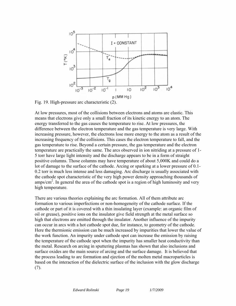
Fig. 19. High-pressure arc characteristic (2). At low pressures, most of the collisions between electrons and atoms are elastic. This means that electrons give only a small fraction of its kinetic energy to an atom. The energy transferred to the gas causes the temperature to rise. At low pressures, the difference between the electron temperature and the gas temperature is very large. With increasing pressure, however, the electrons lose more energy to the atom as a result of the increasing frequency of the collisions. This cases the electron temperature to fall, and the gas temperature to rise. Beyond a certain pressure, the gas temperature and the electron temperature are practically the same. The arcs observed in ion nitriding at a pressure of 1-5 torr have large light intensity and the discharge appears to be in a form of straight positive columns. Those columns may have temperature of about 5,000K and could do a lot of damage to the surface of the cathode. Arcing or sparking at a lower pressure of 0.1-0.2 torr is much less intense and less damaging. Arc discharge is usually associated with the cathode spot characteristic of the very high power density approaching thousands of amps/cm2. In general the area of the cathode spot is a region of high luminosity and very high temperature. There are various theories explaining the arc formation. All of them attribute arc formation to various imperfections or non-homogeneity of the cathode surface. If the cathode or part of it is covered with a thin insulating layer (example: an organic film of oil or grease), positive ions on the insulator give field strength at the metal surface so high that electrons are emitted through the insulator. Another influence of the impurity can occur in arcs with a hot cathode spot due, for instance, to geometry of the cathode. Here the thermionic emission can be much increased by impurities that lower the value of the work function. An impurity under cathode spot can increase the emission by raising the temperature of the cathode spot when the impurity has smaller heat conductivity than the metal. Research on arcing in sputtering plasmas has shown that also inclusions and surface oxides are the main source of arcing and the surface damage. It is believed that the process leading to arc formation and ejection of the molten metal macroparticles is based on the interaction of the dielectric surface of the inclusion with the glow discharge (7).
Edward Rolinski Page 19 1/7/2009
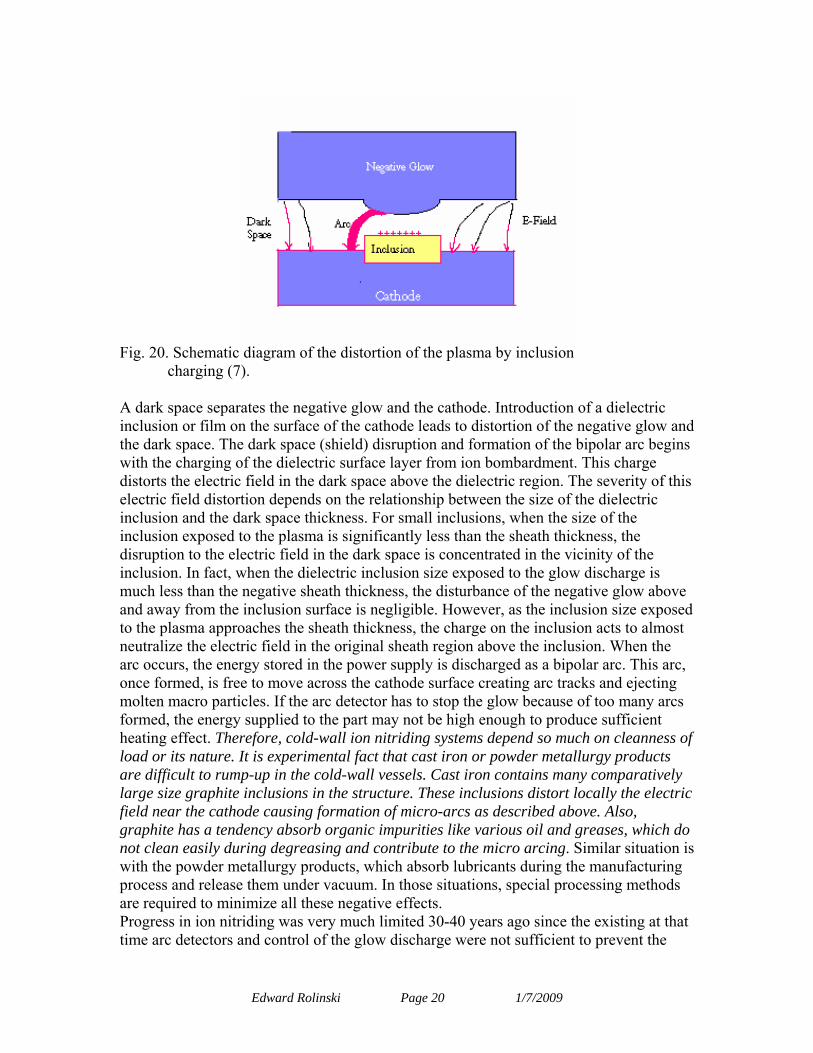
Fig. 20. Schematic diagram of the distortion of the plasma by inclusion
charging (7). A dark space separates the negative glow and the cathode. Introduction of a dielectric inclusion or film on the surface of the cathode leads to distortion of the negative glow and the dark space. The dark space (shield) disruption and formation of the bipolar arc begins with the charging of the dielectric surface layer from ion bombardment. This charge distorts the electric field in the dark space above the dielectric region. The severity of this electric field distortion depends on the relationship between the size of the dielectric inclusion and the dark space thickness. For small inclusions, when the size of the inclusion exposed to the plasma is significantly less than the sheath thickness, the disruption to the electric field in the dark space is concentrated in the vicinity of the inclusion. In fact, when the dielectric inclusion size exposed to the glow discharge is much less than the negative sheath thickness, the disturbance of the negative glow above and away from the inclusion surface is negligible. However, as the inclusion size exposed to the plasma approaches the sheath thickness, the charge on the inclusion acts to almost neutralize the electric field in the original sheath region above the inclusion. When the arc occurs, the energy stored in the power supply is discharged as a bipolar arc. This arc, once formed, is free to move across the cathode surface creating arc tracks and ejecting molten macro particles. If the arc detector has to stop the glow because of too many arcs formed, the energy supplied to the part may not be high enough to produce sufficient heating effect. Therefore, cold-wall ion nitriding systems depend so much on cleanness of load or its nature. It is experimental fact that cast iron or powder metallurgy products are difficult to rump-up in the cold-wall vessels. Cast iron contains many comparatively large size graphite inclusions in the structure. These inclusions distort locally the electric field near the cathode causing formation of micro-arcs as described above. Also, graphite has a tendency absorb organic impurities like various oil and greases, which do not clean easily during degreasing and contribute to the micro arcing. Similar situation is with the powder metallurgy products, which absorb lubricants during the manufacturing process and release them under vacuum. In those situations, special processing methods are required to minimize all these negative effects. Progress in ion nitriding was very much limited 30-40 years ago since the existing at that time arc detectors and control of the glow discharge were not sufficient to prevent the
Edward Rolinski Page 20 1/7/2009
surface damage of the treated parts. In these days, tremendous progress in electronic and computer industries as well as introduction of the pulse power supplies allows control of this unwanted phenomenon. 3. Mechanism of ion nitriding Considerable progress was made in regards to mechanism of ion nitriding in recent years. The important fact is that most of the researches agreed that the sputtering model proposed by Kolbel in 1965 can’t be considered as a valid model any more (8). Glow discharge has ability to generate chemically active species in nitrogen containing gas mixture, therefore allowing control of the chemical reactions on the substrate surface. These species are obtained as a result of inelastic collisions between electrons and gas molecules. This exchange of the energy leads to the formation of ions, atoms in statu nascendi and various radicals that can react with each other to form other excited species. At the same time surface atoms of the solid as well as many of the adsorbed gas molecules, are sputtered by impinging ions or energetic neutrals. The situation is very complex in the plasma containing various gases. The simplified model based on the work of J. L. Marchand et al (9) is presented in Fig.21.
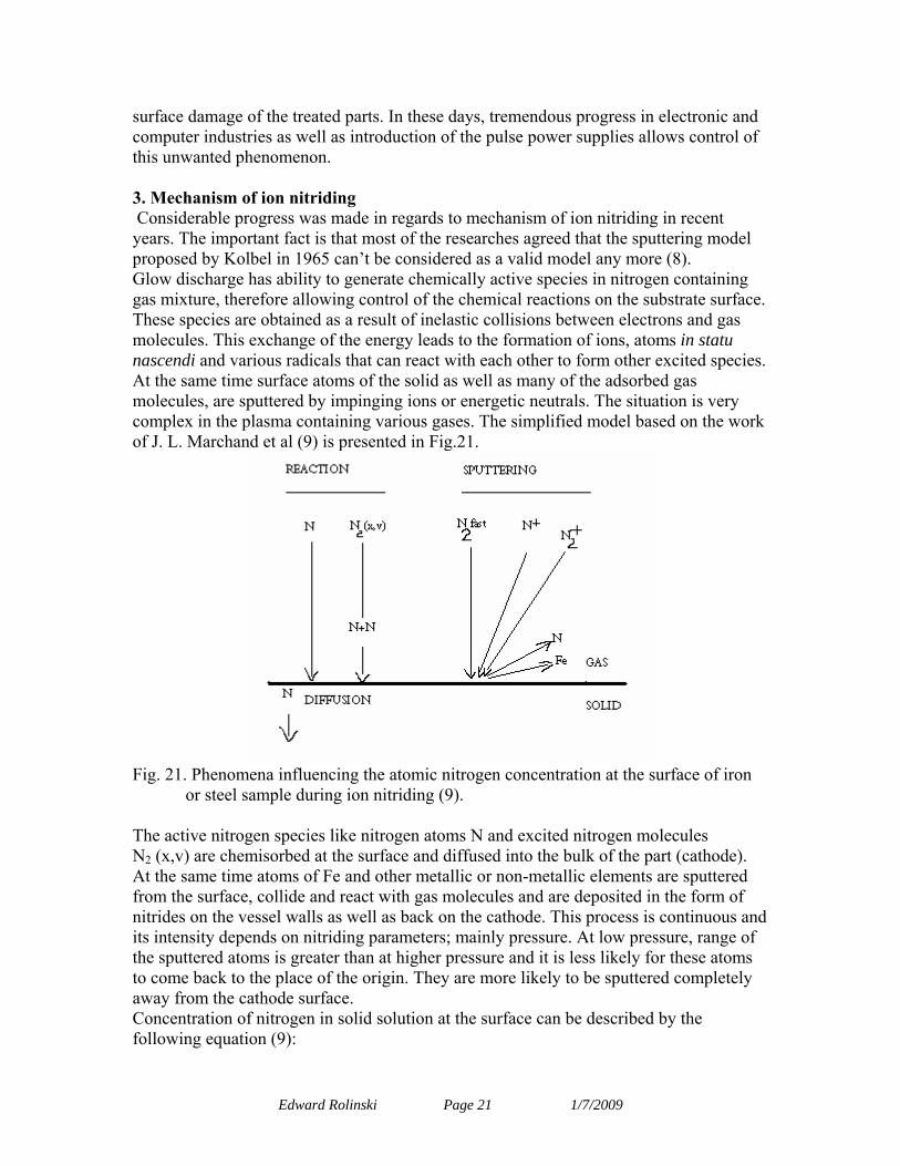
Fig. 21. Phenomena influencing the atomic nitrogen concentration at the surface of iron
or steel sample during ion nitriding (9). The active nitrogen species like nitrogen atoms N and excited nitrogen molecules N2 (x,v) are chemisorbed at the surface and diffused into the bulk of the part (cathode). At the same time atoms of Fe and other metallic or non-metallic elements are sputtered from the surface, collide and react with gas molecules and are deposited in the form of nitrides on the vessel walls as well as back on the cathode. This process is continuous and its intensity depends on nitriding parameters; mainly pressure. At low pressure, range of the sputtered atoms is greater than at higher pressure and it is less likely for these atoms to come back to the place of the origin. They are more likely to be sputtered completely away from the cathode surface. Concentration of nitrogen in solid solution at the surface can be described by the following equation (9):
Edward Rolinski Page 21 1/7/2009
(1) Where: Cs,t is the nitrogen mass fraction at the solid surface at the time t, A is a sputtering term which depends on the nature of the surface (pure iron, γ’, ε, α), the ionic current and on the voltage drop in the cathodic fall (effect of pressure), B is a term depending on the reactivity of the discharge (densities of reactive species on the surface) and thus on all of the operating parameters, C is the nitrogen mass fraction corresponding to the threshold stability limit of the compound formed at the surface at the considered temperature. If the surface is pure iron, i.e. no nitride is formed, C=0. Thickness of the compound zone can be expressed by the following expression (10):
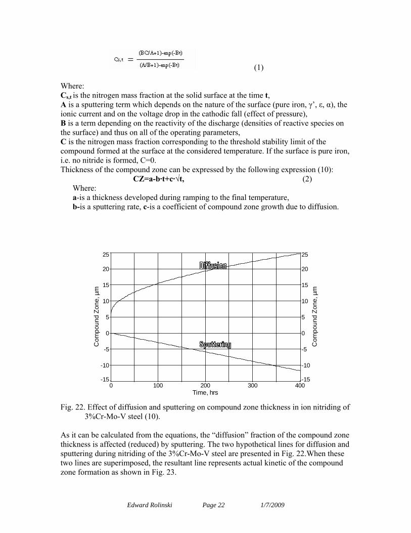
CZ=a-b·t+c·√t, (2) Where: a-is a thickness developed during ramping to the final temperature, b-is a sputtering rate, c-is a coefficient of compound zone growth due to diffusion.
0 100 200 300 400Time, hrs
-15
-10
-5
0
5
10
15
20
25
Com
poun
d Zo
ne, µ
m
-15
-10
-5
0
5
10
15
20
25
Com
poun
d Zo
ne, µ
m
Fig. 22. Effect of diffusion and sputtering on compound zone thickness in ion nitriding of
3%Cr-Mo-V steel (10). As it can be calculated from the equations, the “diffusion” fraction of the compound zone thickness is affected (reduced) by sputtering. The two hypothetical lines for diffusion and sputtering during nitriding of the 3%Cr-Mo-V steel are presented in Fig. 22.When these two lines are superimposed, the resultant line represents actual kinetic of the compound zone formation as shown in Fig. 23.
Edward Rolinski Page 22 1/7/2009
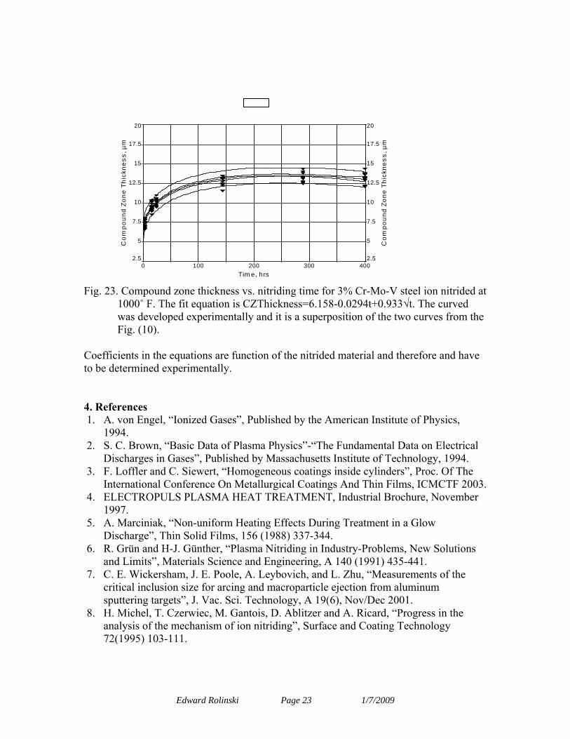
Fig. 3
0 100 200 300 400Tim e, hrs
2.5
5
7.5
10
12.5
15
17.5
20C
ompo
und
Zone
Thi
ckne
ss, µ
m
2.5
5
7.5
10
12.5
15
17.5
20
Com
poun
d Zo
ne T
hick
ness
, µm
Fig. 23. Compound zone thickness vs. nitriding time for 3% Cr-Mo-V steel ion nitrided at
1000˚ F. The fit equation is CZThickness=6.158-0.0294ּt+0.933√t. The curved was developed experimentally and it is a superposition of the two curves from the Fig. (10).
Coefficients in the equations are function of the nitrided material and therefore and have to be determined experimentally. 4. References 1. A. von Engel, “Ionized Gases”, Published by the American Institute of Physics,
1994. 2. S. C. Brown, “Basic Data of Plasma Physics”-“The Fundamental Data on Electrical
Discharges in Gases”, Published by Massachusetts Institute of Technology, 1994. 3. F. Loffler and C. Siewert, “Homogeneous coatings inside cylinders”, Proc. Of The
International Conference On Metallurgical Coatings And Thin Films, ICMCTF 2003. 4. ELECTROPULS PLASMA HEAT TREATMENT, Industrial Brochure, November
1997. 5. A. Marciniak, “Non-uniform Heating Effects During Treatment in a Glow
Discharge”, Thin Solid Films, 156 (1988) 337-344. 6. R. Grün and H-J. Günther, “Plasma Nitriding in Industry-Problems, New Solutions
and Limits”, Materials Science and Engineering, A 140 (1991) 435-441. 7. C. E. Wickersham, J. E. Poole, A. Leybovich, and L. Zhu, “Measurements of the
critical inclusion size for arcing and macroparticle ejection from aluminum sputtering targets”, J. Vac. Sci. Technology, A 19(6), Nov/Dec 2001.
8. H. Michel, T. Czerwiec, M. Gantois, D. Ablitzer and A. Ricard, “Progress in the analysis of the mechanism of ion nitriding”, Surface and Coating Technology 72(1995) 103-111.
Edward Rolinski Page 23 1/7/2009

Edward Rolinski Page 24 1/7/2009
9. J. L. Marchand, D. Ablitzer and M. Gantois, in T. Spalvins and W. L. Kovacs (ed) Proc. Conf. On Ion Nitriding and Ion Carburizing, Cincinnati. OH, 1989, AMS, Metals Park, OH, 1990, p.67.
10. E. Rolinski and G. Sharp, “ The Effect of Sputtering on Kinetic of Compound Zone Formation in the Plasma Nitriding of Cr-Mo-V Steel”, Journal of Materials Engineering and Performance, 10 (4) August 2001.


![Klystron - Medicinsk strålningsfysik, Lund · conditions.[1] An ion pump ionizes gases and employs a strong electrical potential, typically 3kV to 7kV, to accelerate them into a](https://img.pdfslide.tips/doc/110x75/5f172f72cc0e823bcd2f2d94/klystron-medicinsk-strlningsfysik-lund-conditions1-an-ion-pump-ionizes-gases.jpg)