Embed Size (px)
Citation preview
1
in cooperation with
Frits J.K. Buesink, Senior Researcher EMC
Picture or Drawing 20.7 x 8.6 cm
UNIVERSITY OF TWENTE.
TELECOMMUNICATION ENGINEERING.
Electromagnetic Compatibility Basics
Engineering Compatible Equipment and Systems
UNIVERSITY OF TWENTE.
TELECOMMUNICATION ENGINEERING.
in cooperation withStoringsmechanismes in Installaties
Definition of EMC
“The ability of the System to Operate according to its Specifications
in its Intended Electromagnetic Environment”
“Without generating Unacceptable Electromagnetic Emissions
into that Environment”
2
2
UNIVERSITY OF TWENTE.
TELECOMMUNICATION ENGINEERING.
in cooperation withStoringsmechanismes in Installaties
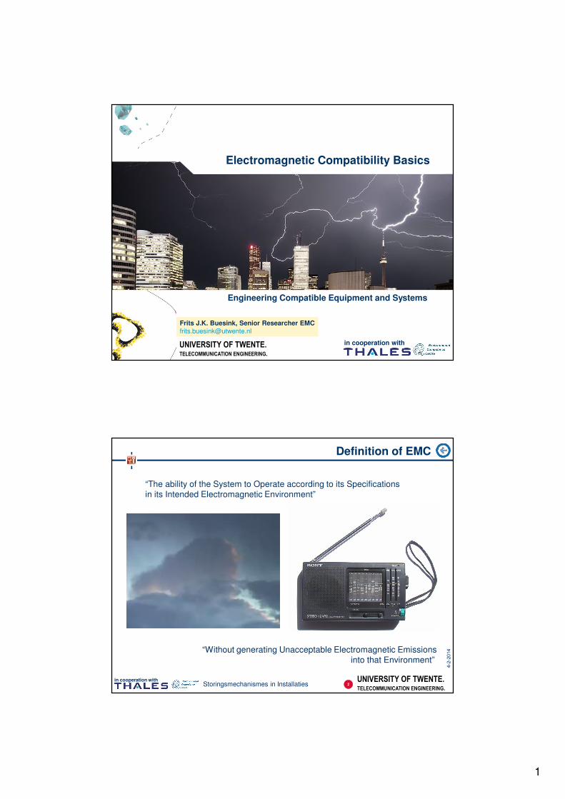
Three Criteria for EMC
1. No (intolerable) emissions into the environment
2. Operate satisfactorily in its EM environment
3. Not cause interference with itself
3
UNIVERSITY OF TWENTE.
TELECOMMUNICATION ENGINEERING.
in cooperation withStoringsmechanismes in Installaties
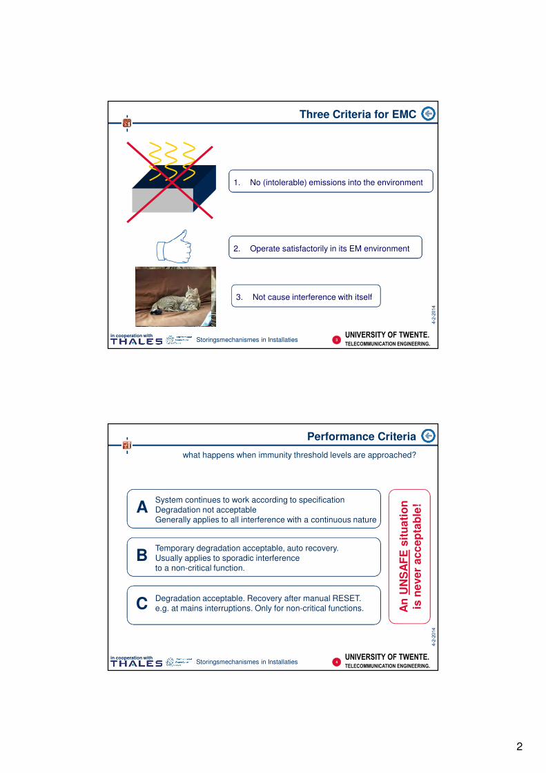
Performance Criteria
what happens when immunity threshold levels are approached?
ASystem continues to work according to specification
Degradation not acceptable
Generally applies to all interference with a continuous nature
BTemporary degradation acceptable, auto recovery.
Usually applies to sporadic interference
to a non-critical function.
CDegradation acceptable. Recovery after manual RESET.
e.g. at mains interruptions. Only for non-critical functions. An
UN
SA
FE
sit
ua
tio
nis
ne
ve
r a
cc
ep
tab
le!
4
3
UNIVERSITY OF TWENTE.
TELECOMMUNICATION ENGINEERING.
in cooperation withStoringsmechanismes in Installaties
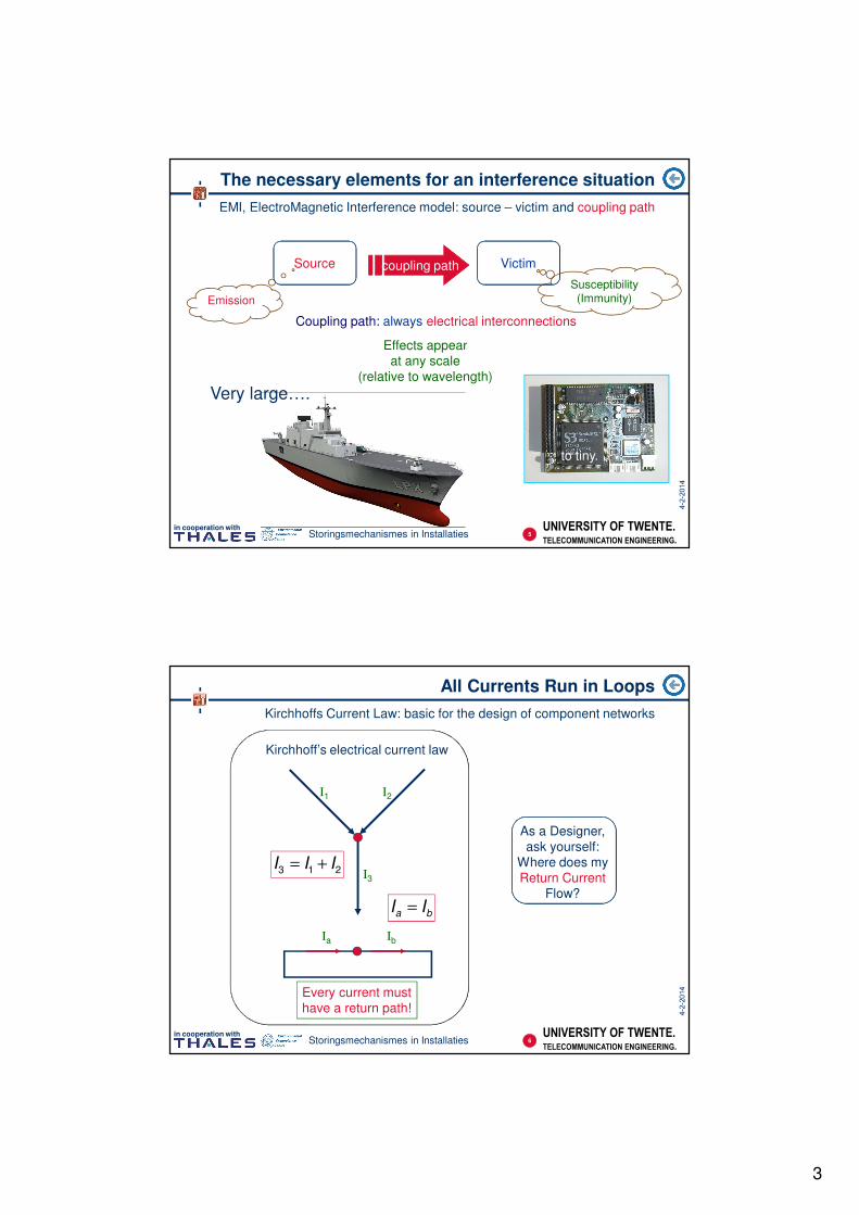
The necessary elements for an interference situation
EMI, ElectroMagnetic Interference model: source – victim and coupling path
Source Victimcoupling pathcoupling path
Coupling path: always electrical interconnections
to tiny.
Emission
Susceptibility(Immunity)
Very large….
this can be demonstrated using:
a noise generator
a radio receiver
and some cables
Effects appear
at any scale
(relative to wavelength)
5
UNIVERSITY OF TWENTE.
TELECOMMUNICATION ENGINEERING.
in cooperation withStoringsmechanismes in Installaties
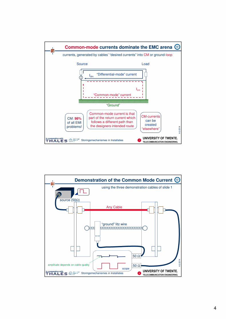
All Currents Run in Loops
Kirchhoffs Current Law: basic for the design of component networks
I1 I2
I3
Ia Ib
Kirchhoff’s electrical current law
213 III +=
ba II =
Every current must
have a return path!
As a Designer,
ask yourself:
Where does my
Return Current
Flow?
6
4
UNIVERSITY OF TWENTE.
TELECOMMUNICATION ENGINEERING.
in cooperation withStoringsmechanismes in Installaties
Common-mode currents dominate the EMC arena
currents, generated by cables’ “desired currents” into CM or ground-loop
Source Load
“Ground”
“Differential-mode” currentIdm
Icm
“Common-mode” current
CM: 98%of all EMI
problems!
Common-mode current is that
part of the return current which
follows a different path than
the designers intended route
CM-currents
can be
created
“elsewhere”
7
UNIVERSITY OF TWENTE.
TELECOMMUNICATION ENGINEERING.
in cooperation withStoringsmechanismes in Installaties
Demonstration of the Common Mode Current
using the three demonstration cables of slide 1
50 Ω
source (50Ω)
scope
“ground” litz wire
Any Cable
8
50 Ω
amplitude depends on cable quality
5
UNIVERSITY OF TWENTE.
TELECOMMUNICATION ENGINEERING.
in cooperation withStoringsmechanismes in Installaties
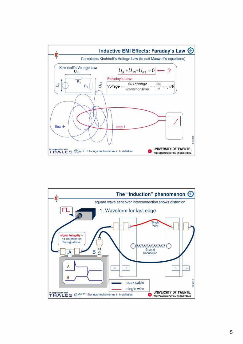
Kirchhoff’s Voltage Law
Us
R1
R2
UR1
UR
2
021 =++ RRS UUU
Inductive EMI Effects: Faraday’s Law
Completes Kirchhoff’s Voltage Law (to suit Maxwell’s equations)
loop 1flux Φflux Φ
Faraday’s Law:
?
9
UNIVERSITY OF TWENTE.
TELECOMMUNICATION ENGINEERING.
in cooperation withStoringsmechanismes in Installaties
The “Induction” phenomenon
square wave sent over interconnection shows distortion
50
Ω
coax cable
single wire
1. Waveform for fast edge
A B
A
B
signal integrity =
no distortion on
the signal line
10
Ground
Connection
Single
Wire
6
UNIVERSITY OF TWENTE.
TELECOMMUNICATION ENGINEERING.
in cooperation withStoringsmechanismes in Installaties
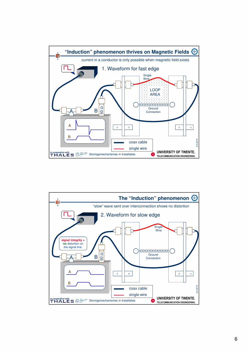
“Induction” phenomenon thrives on Magnetic Fields
current in a conductor is only possible when magnetic field exists
50
Ω
coax cable
single wire
1. Waveform for fast edge
A B
A
B
11
Ground
Connection
Single
Wire
LOOP
AREA
UNIVERSITY OF TWENTE.
TELECOMMUNICATION ENGINEERING.
in cooperation withStoringsmechanismes in Installaties
The “Induction” phenomenon
“slow” wave sent over interconnection shows no distortion
50
Ω
coax cable
single wire
2. Waveform for slow edge
A B
A
B
signal integrity =
no distortion on
the signal line
12
Ground
Connection
Single
Wire
7
UNIVERSITY OF TWENTE.
TELECOMMUNICATION ENGINEERING.
in cooperation withStoringsmechanismes in Installaties
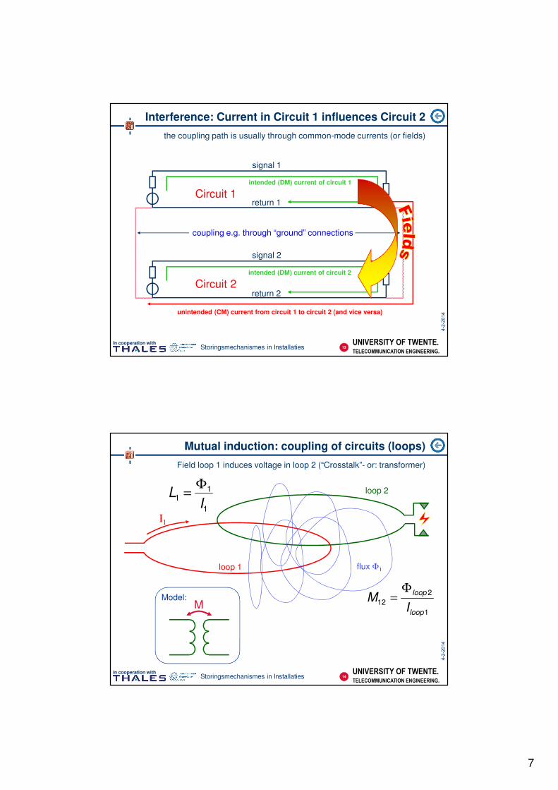
Interference: Current in Circuit 1 influences Circuit 2
the coupling path is usually through common-mode currents (or fields)
signal 1
return 1
signal 2
return 2
coupling e.g. through “ground” connections
Circuit 1
Circuit 2
intended (DM) current of circuit 1
intended (DM) current of circuit 2
unintended (CM) current from circuit 1 to circuit 2 (and vice versa)
13
UNIVERSITY OF TWENTE.
TELECOMMUNICATION ENGINEERING.
in cooperation withStoringsmechanismes in Installaties
Mutual induction: coupling of circuits (loops)
Field loop 1 induces voltage in loop 2 (“Crosstalk”- or: transformer)
I1
loop 1
loop 2
MModel:
flux Φ11
2
12
loop
loop
IM
Φ=
1
11
IL
Φ=
14
8
UNIVERSITY OF TWENTE.
TELECOMMUNICATION ENGINEERING.
in cooperation withStoringsmechanismes in Installaties
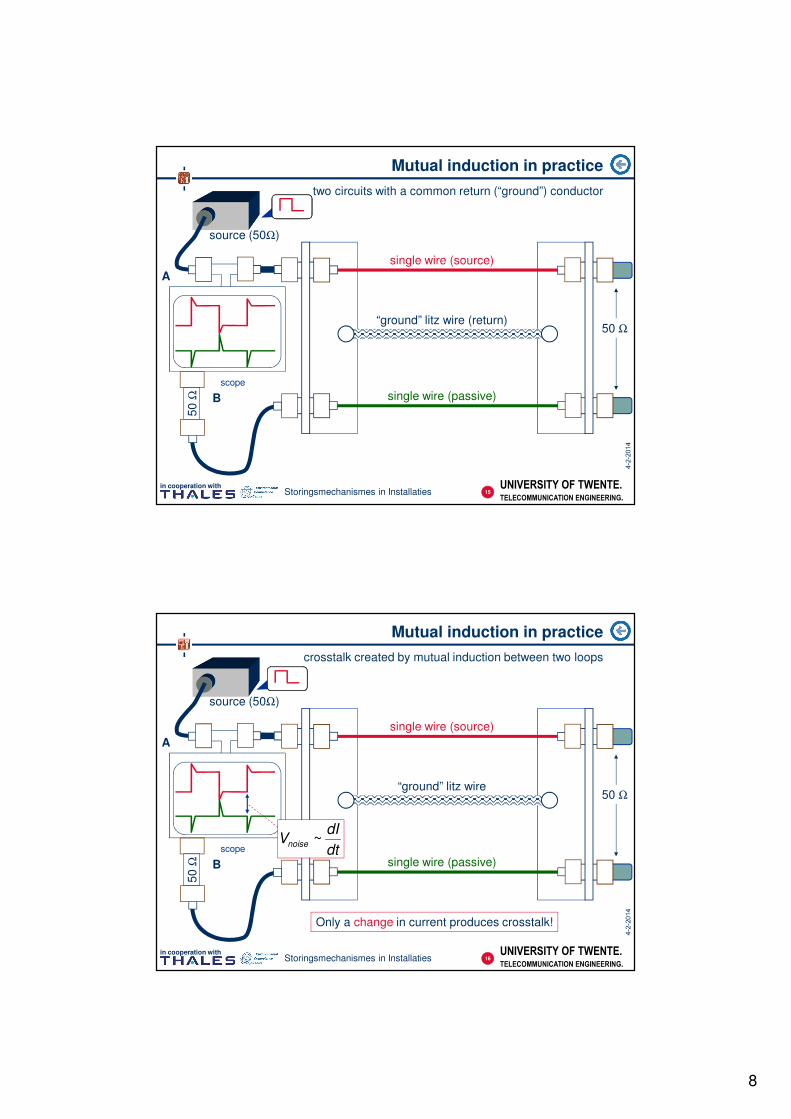
Mutual induction in practice
two circuits with a common return (“ground”) conductor
source (50Ω)
scope
“ground” litz wire (return)
single wire (source)
single wire (passive)
15
50 Ω
B
50
Ω
A
UNIVERSITY OF TWENTE.
TELECOMMUNICATION ENGINEERING.
in cooperation withStoringsmechanismes in Installaties
Mutual induction in practice
crosstalk created by mutual induction between two loops
source (50Ω)
scope
“ground” litz wire
single wire (source)
single wire (passive)
Only a change in current produces crosstalk!
16
50 Ω
dt
dIVnoise ~
B
50
Ω
A
9
UNIVERSITY OF TWENTE.
TELECOMMUNICATION ENGINEERING.
in cooperation withStoringsmechanismes in Installaties
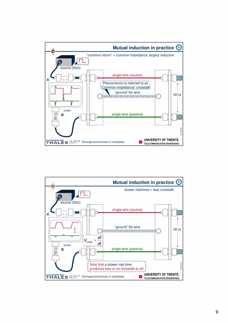
Mutual induction in practice
“common return” = common impedance, largely inductive
source (50Ω)
scope
“ground” litz wire
single wire (source)
single wire (passive)
“Common-Impedance” crosstalk
Phenomenon is referred to as
“Common-Impedance” crosstalk
17
50 Ω
B
50
Ω
A
UNIVERSITY OF TWENTE.
TELECOMMUNICATION ENGINEERING.
in cooperation withStoringsmechanismes in Installaties
Mutual induction in practice
slower risetimes = less crosstalk
source (50Ω)
scope
“ground” litz wire
single wire (source)
single wire (passive)
Note that a slower rise time
produces less or no crosstalk at all!
18
50 Ω
dt
dIVnoise ~
B
50
Ω
A
10
UNIVERSITY OF TWENTE.
TELECOMMUNICATION ENGINEERING.
in cooperation withStoringsmechanismes in Installaties
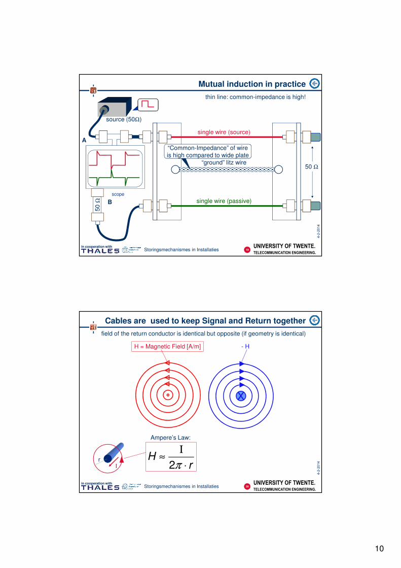
Mutual induction in practice
thin line: common-impedance is high!
source (50Ω)
scope
“ground” litz wire
single wire (source)
single wire (passive)
19
50 Ω
“Common-Impedance” of wire
is high compared to wide plate
B
50
Ω
A
UNIVERSITY OF TWENTE.
TELECOMMUNICATION ENGINEERING.
in cooperation withStoringsmechanismes in Installaties
Cables are used to keep Signal and Return together
field of the return conductor is identical but opposite (if geometry is identical)
H = Magnetic Field [A/m] - H
I
rr
H⋅
Ι≈
π2
Ampere’s Law:
20
11
UNIVERSITY OF TWENTE.
TELECOMMUNICATION ENGINEERING.
in cooperation withStoringsmechanismes in Installaties
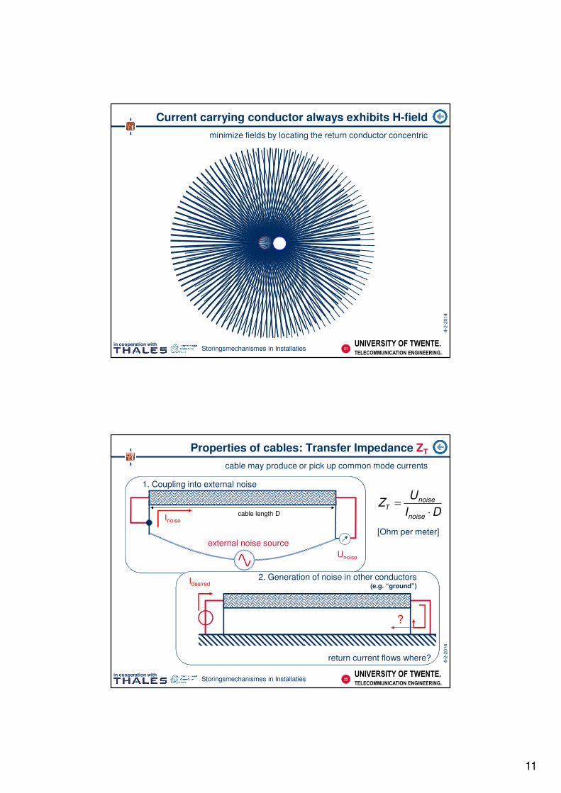
Current carrying conductor always exhibits H-field
minimize fields by locating the return conductor concentric
21
UNIVERSITY OF TWENTE.
TELECOMMUNICATION ENGINEERING.
in cooperation withStoringsmechanismes in Installaties
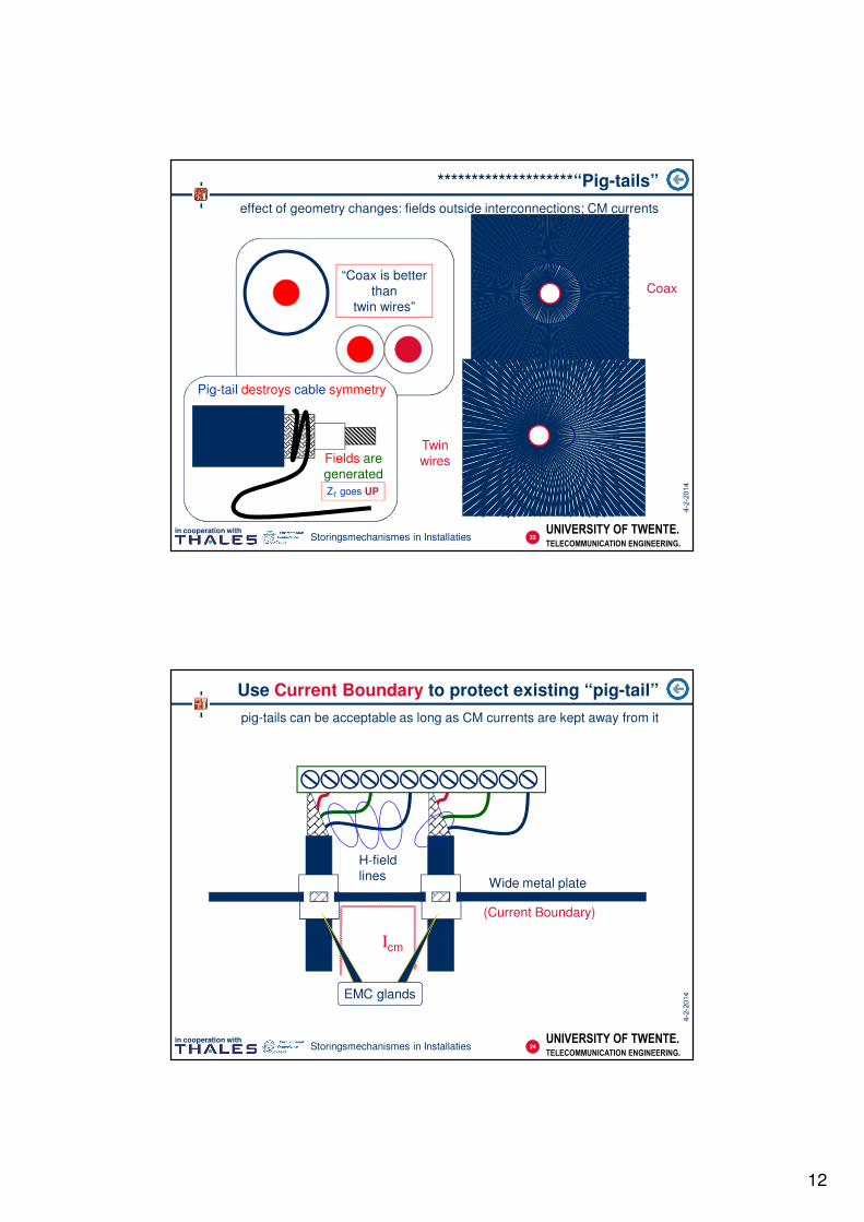
external noise source
Inoise
Unoise
1. Coupling into external noise
cable length D
Properties of cables: Transfer Impedance ZT
cable may produce or pick up common mode currents
Idesired
return current flows where?
?
2. Generation of noise in other conductors(e.g. “ground”)
DI
UZ
noise
noiseT
⋅=
[Ohm per meter]
22
12
UNIVERSITY OF TWENTE.
TELECOMMUNICATION ENGINEERING.
in cooperation withStoringsmechanismes in Installaties
********************“Pig-tails”
effect of geometry changes: fields outside interconnections; CM currents
when
compared…
“Coax is better
than
twin wires”
Coax
Twin
wires
Pig-tail destroys cable symmetry
Fields are
generated
ZT goes UP
23
UNIVERSITY OF TWENTE.
TELECOMMUNICATION ENGINEERING.
in cooperation withStoringsmechanismes in Installaties
Icm
Use Current Boundary to protect existing “pig-tail”
pig-tails can be acceptable as long as CM currents are kept away from it
H-field
linesWide metal plate
(Current Boundary)
EMC glands
24
13
UNIVERSITY OF TWENTE.
TELECOMMUNICATION ENGINEERING.
in cooperation withStoringsmechanismes in Installaties
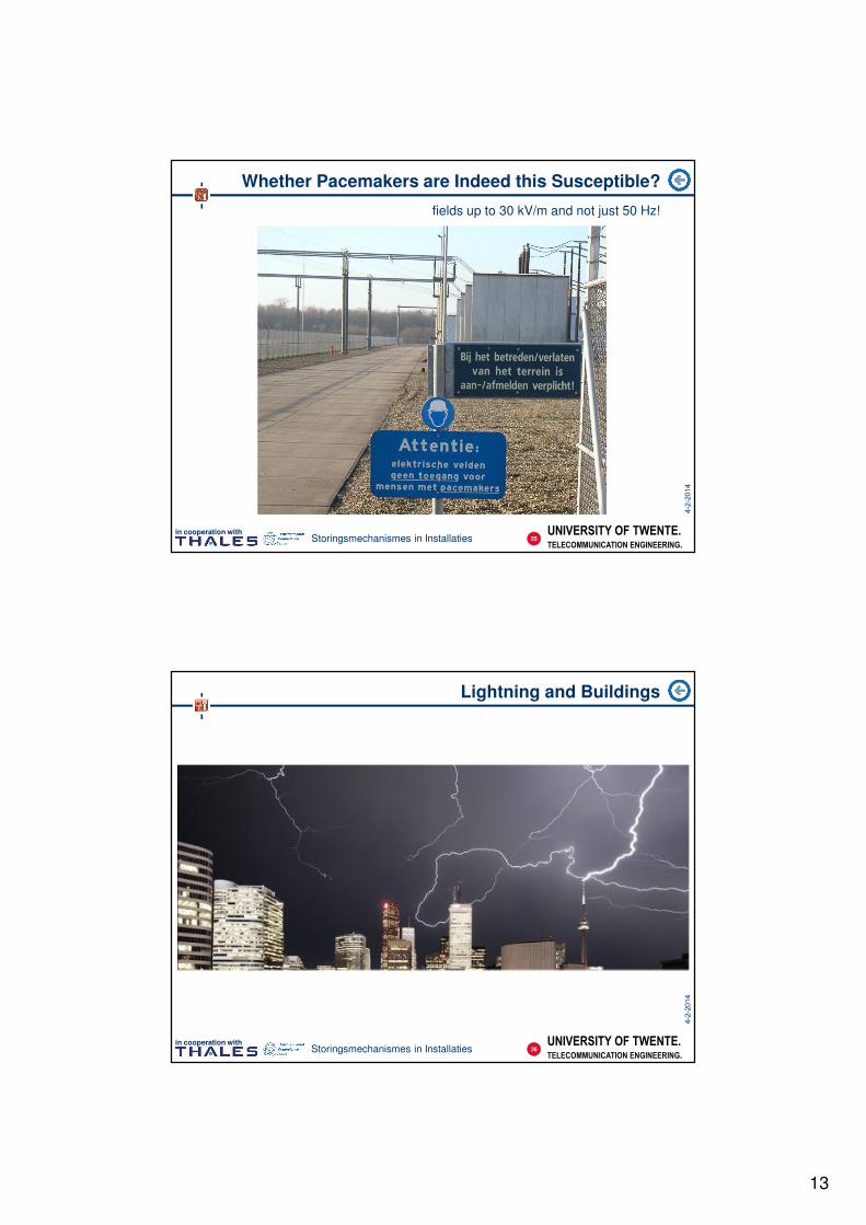
Whether Pacemakers are Indeed this Susceptible?
fields up to 30 kV/m and not just 50 Hz!
25
UNIVERSITY OF TWENTE.
TELECOMMUNICATION ENGINEERING.
in cooperation withStoringsmechanismes in Installaties
Lightning and Buildings
26
14
UNIVERSITY OF TWENTE.
TELECOMMUNICATION ENGINEERING.
in cooperation withStoringsmechanismes in Installaties
Lightning and Buildings
27
UNIVERSITY OF TWENTE.
TELECOMMUNICATION ENGINEERING.
in cooperation withStoringsmechanismes in Installaties
Insulation in Lightning Protection
keep lightning current on the outside of the building
Exte
rna
l “S
hie
ld”
Inte
rnal w
irin
g
surge
protect
cabinet
1
2
3
4
5
powerdata
RV ⋅Ι≈∆
Ι Ι
Exte
rna
l co
nd
uctin
g s
tru
ctu
re
Current
Boundary
28
15
UNIVERSITY OF TWENTE.
TELECOMMUNICATION ENGINEERING.
in cooperation withStoringsmechanismes in Installaties
Lightning and Airplanes
29
UNIVERSITY OF TWENTE.
TELECOMMUNICATION ENGINEERING.
in cooperation withStoringsmechanismes in Installaties
ElectroStatic Discharge
charges built on persons or equipment cause electric sparks (and currents)
30
16
UNIVERSITY OF TWENTE.
TELECOMMUNICATION ENGINEERING.
in cooperation withStoringsmechanismes in Installaties
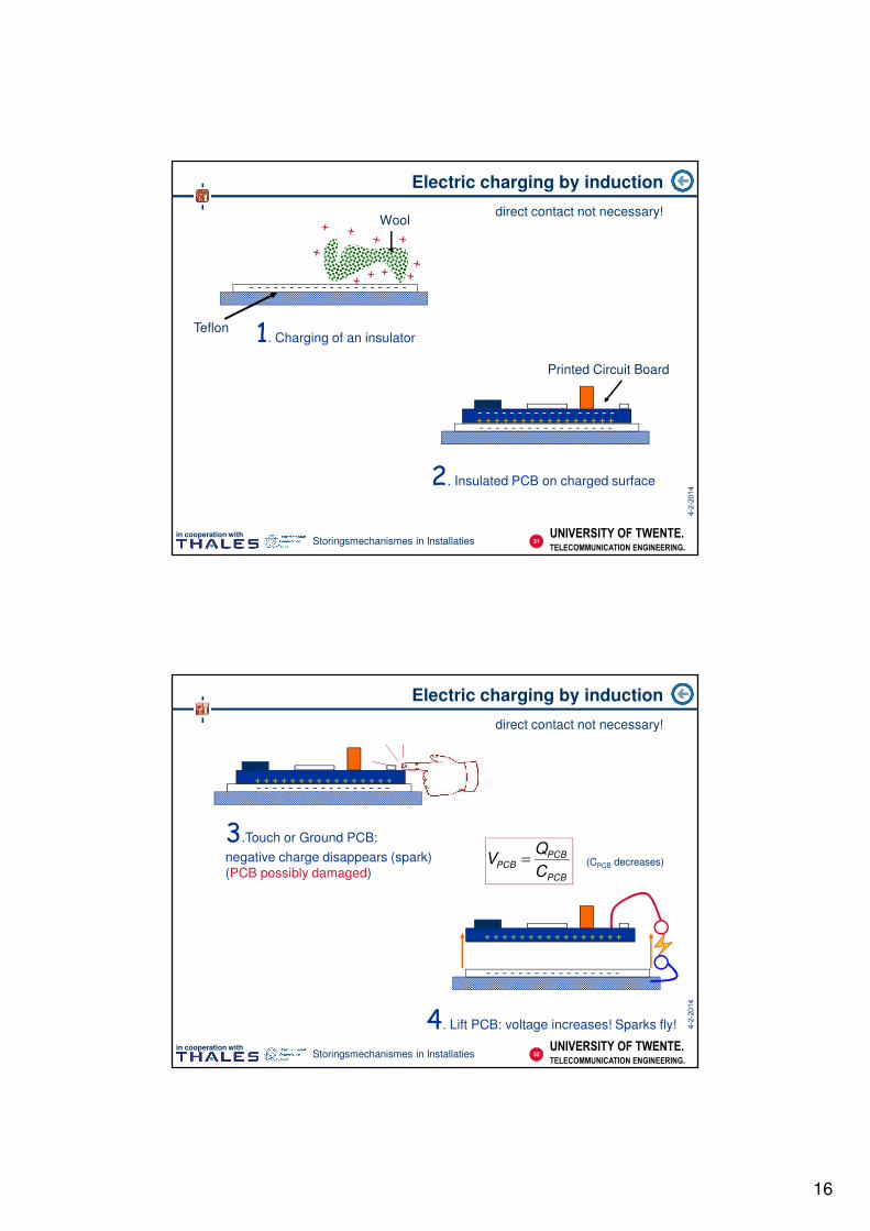
Electric charging by induction
direct contact not necessary!
Teflon
Wool
Printed Circuit Board
- - - - - - - - - - - - - - - - -+ + + + + + + + + + + + + + + +
1. Charging of an insulator
2. Insulated PCB on charged surface
- - - - - - - - - - - - - - - - - - - -
- - - - - - - - - - - - - - - - -
31
UNIVERSITY OF TWENTE.
TELECOMMUNICATION ENGINEERING.
in cooperation withStoringsmechanismes in Installaties
Electric charging by induction
direct contact not necessary!
+ + + + + + + + + + + + + + + +
3.Touch or Ground PCB:
negative charge disappears (spark)
(PCB possibly damaged)
4. Lift PCB: voltage increases! Sparks fly!
- - - - - - - - - - - - - - - - -
- - - - - - - - - - - - - - - - -
- - - - - - - - - - - - - - - - -
+ + + + + + + + + + + + + + + +
PCB
PCBPCB
C
QV = (CPCB decreases)
32
17
UNIVERSITY OF TWENTE.
TELECOMMUNICATION ENGINEERING.
in cooperation withStoringsmechanismes in Installaties
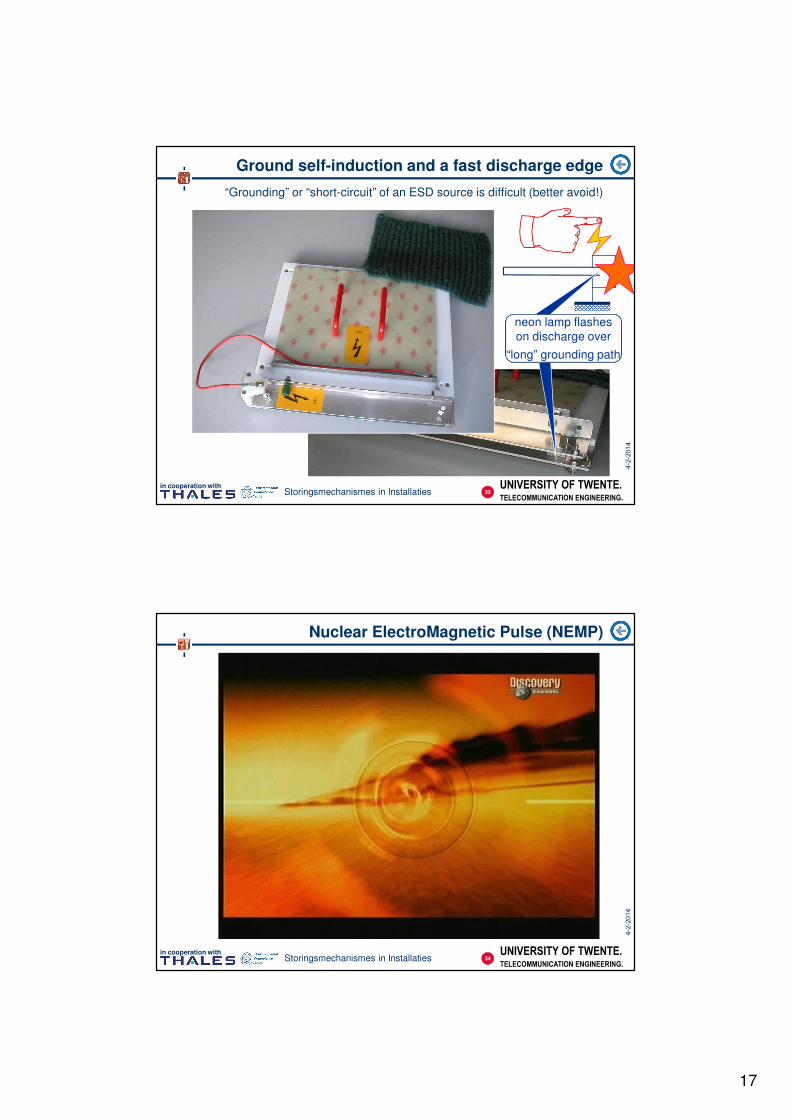
Ground self-induction and a fast discharge edge
“Grounding” or “short-circuit” of an ESD source is difficult (better avoid!)
“long” grounding path
neon lamp flashes
on discharge over
“long” grounding path
33
UNIVERSITY OF TWENTE.
TELECOMMUNICATION ENGINEERING.
in cooperation with
Nuclear ElectroMagnetic Pulse (NEMP)
34Storingsmechanismes in Installaties
18
UNIVERSITY OF TWENTE.
TELECOMMUNICATION ENGINEERING.
in cooperation with
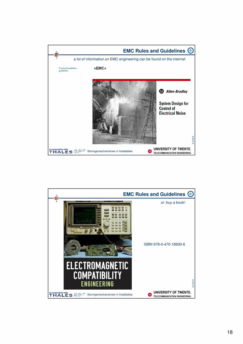
EMC Rules and Guidelines
a lot of information on EMC engineering can be found on the internet
35Storingsmechanismes in Installaties
UNIVERSITY OF TWENTE.
TELECOMMUNICATION ENGINEERING.
in cooperation with
EMC Rules and Guidelines
or: buy a book!
36Storingsmechanismes in Installaties
ISBN 978-0-470-18930-6
19
UNIVERSITY OF TWENTE.
TELECOMMUNICATION ENGINEERING.
in cooperation with
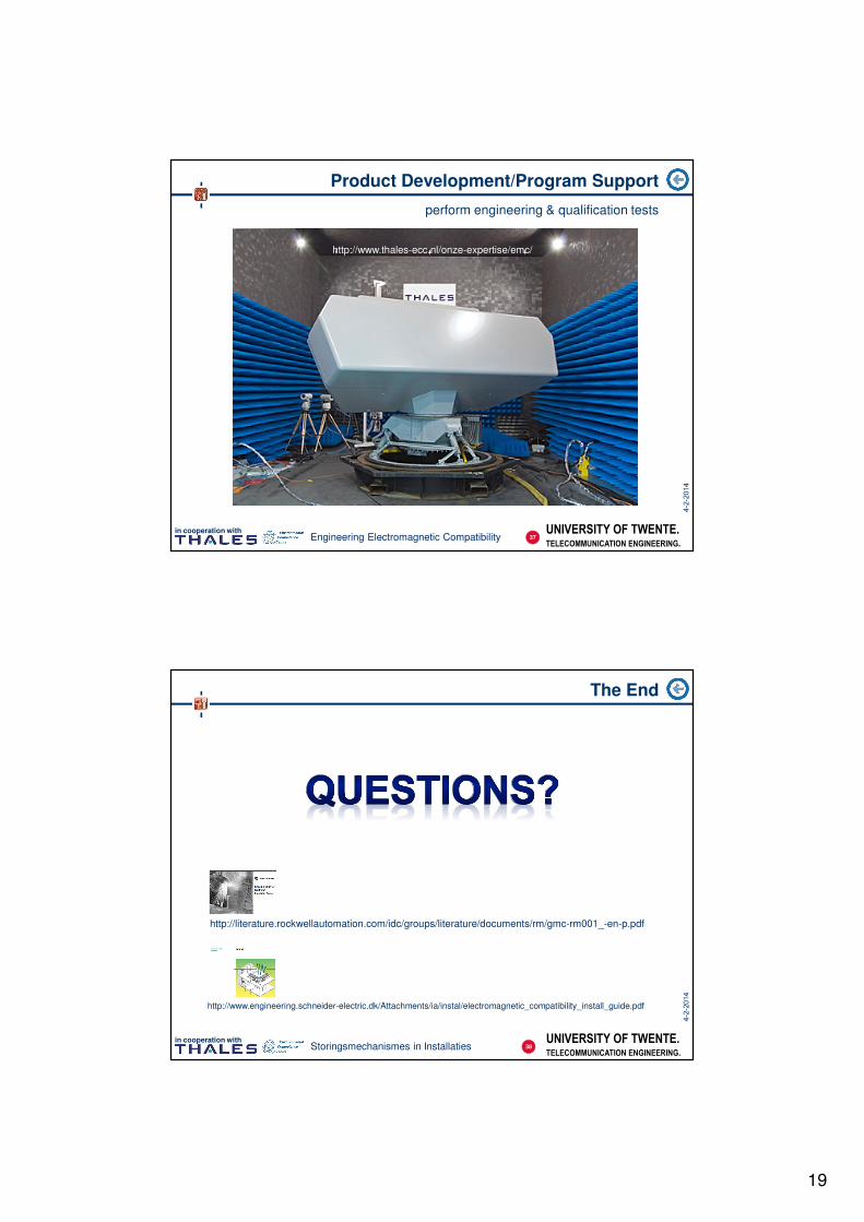
Product Development/Program Support
perform engineering & qualification tests
37Engineering Electromagnetic Compatibility
http://www.thales-ecc.nl/onze-expertise/emc/
UNIVERSITY OF TWENTE.
TELECOMMUNICATION ENGINEERING.
in cooperation with
The End
38Storingsmechanismes in Installaties
http://literature.rockwellautomation.com/idc/groups/literature/documents/rm/gmc-rm001_-en-p.pdf
http://www.engineering.schneider-electric.dk/Attachments/ia/instal/electromagnetic_compatibility_install_guide.pdf
20
UNIVERSITY OF TWENTE.
TELECOMMUNICATION ENGINEERING.
in cooperation withEngineering Electromagnetic Compatibility
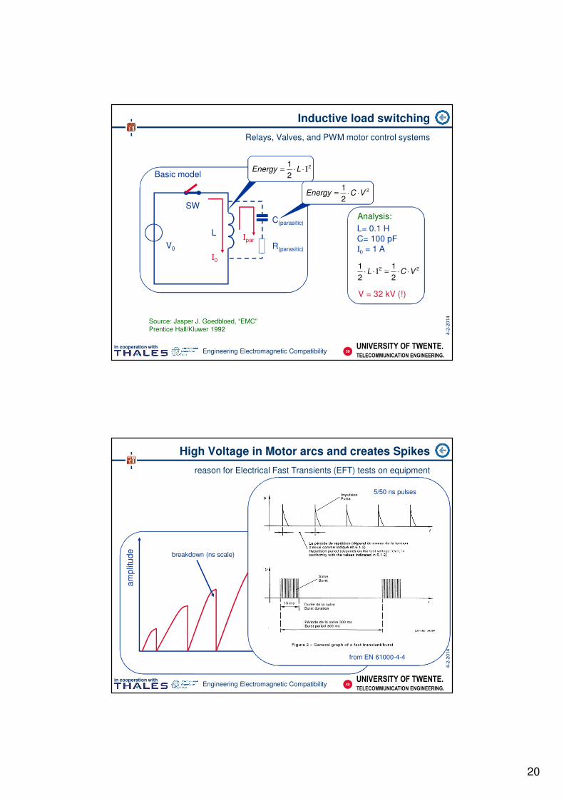
Inductive load switching
Relays, Valves, and PWM motor control systems
V0
SW
L
C(parasitic)
R(parasitic)
Basic model
Ι0
2
2
1Ι⋅⋅= LEnergy
Ιpar
2
2
1VCEnergy ⋅⋅=
22
2
1
2
1VCL ⋅⋅=Ι⋅⋅
L= 0.1 H
C= 100 pF
Ι0 = 1 A
V = 32 kV (!)
Analysis:
Source: Jasper J. Goedbloed, “EMC”
Prentice Hall/Kluwer 1992
39
UNIVERSITY OF TWENTE.
TELECOMMUNICATION ENGINEERING.
in cooperation withEngineering Electromagnetic Compatibility
High Voltage in Motor arcs and creates Spikes
reason for Electrical Fast Transients (EFT) tests on equipment
am
plit
ud
e
time (µs scale)
breakdown (ns scale)
from EN 61000-4-4
5/50 ns pulses
40