Embed Size (px)
Citation preview
[1]
FAYETTE COUNTY PERMITS AND INSPECTIONS
ELECTRONIC
PERMITTING, DOCUMENT
&
PLAN SUBMITTAL
GUIDELINES
[2]
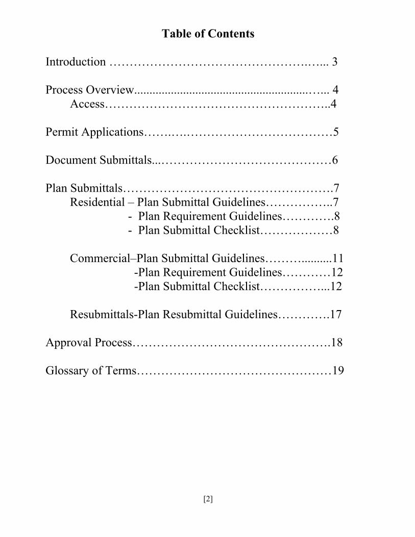
Table of Contents
Introduction ………………………………………….…... 3 Process Overview.........................................................…... 4 Access………………………………………………..4 Permit Applications…….….………………………………5 Document Submittals...……………………………………6 Plan Submittals…………………………………………….7 Residential – Plan Submittal Guidelines……………..7 - Plan Requirement Guidelines………….8 - Plan Submittal Checklist………………8 Commercial–Plan Submittal Guidelines………..........11 -Plan Requirement Guidelines…………12 -Plan Submittal Checklist……………...12
Resubmittals-Plan Resubmittal Guidelines………….17
Approval Process………………………………………….18 Glossary of Terms…………………………………………19
[3]
INTRODUCTION
----
In our continuing effort to improve Customer Service and enhance the Permitting experience; Fayette County Permitting and Inspections Department along with SagesGov Software Systems has implemented a completely paperless online system for submitting all permit applications, associated documentation and building plans. This includes any and all documents currently submit separately with a permit or building plan such as affidavits, water meter receipts, Environmental Health approvals and all revisions to plans or deferred submittal documentation. Effective with the implementation of this new process we will no longer accept paper permit applications or documentation over the counter in our office or via email. All documentation and submittals will be through the new SagesGov Software. In addition to providing these enhancements to the Fayette County permit, documentation and building plan submittal process we will begin accepting all Fire Marshal applications, documentation and plans through this online process.
[4]
PROCESS OVERVIEW
----
ACCESS Anyone requiring access to the new system must register for an account by either using the “Online Application / Plan Review” link on the left hand side of the Fayette County Permits and Inspections Web page or the https://www.sagesgov.com/fayettecounty-ga web address. Contractors must first register for an account for their company as well as list an account administrator as part of the registration process; once approved they can add additional users under their account. Persons that submit documentation for a contractors company (superintendents, foreman, permit expediters etc.) should be setup under the contractors company by the contractor and SHOULD NOT register with a separate account. If for example a permit expediter or foreman registers with a separate account and that account is not registered by the contractor under their account – the separate account holder will not be allowed to submit projects, documentation or plans on the contractors’ behalf. Engineers, Design Professionals etc. may have their own company account in SagesGov and will also be required to be listed under the contractor account as well. An Owner Builder (Homeowner) on a project will not have anyone that can submit on their behalf and will not have anyone listed under their account.
[5]
PERMIT APPLICATIONS
----
Only one (1) project can be submitted per permit application. All permit applications will be required to be submitted electronically by filling out an online application built into the SagesGov system. The primary application forms are built into the system although occasionally, depending on the type of permit and work class selected, additional secondary applications will be required which may include printing, completing and scanning forms into the system.
The key to the SagesGov built in applications is choosing the correct Permit Type and Work Class for your project. These two items set the stage for all other requirements and information needed to complete the application process. If the correct Permit Type or Work Class is not chosen for your project it will not make it beyond the Intake process and will require the correct entries be made and resubmitted.
*For questions about which Permit Type or Work Class to choose please contact the Permits and Inspections Department before submitting the project.
Mandatory fields are required on most online permit applications and must be filled out in order to complete the application submittal process.
[6]
DOCUMENT SUBMITTALS
----
All documents (affidavits, ResChecks, Contractors licenses, water meter receipts, Environmental Health approvals etc.) shall be submitted electronically through the SagesGov system. Each form will be required to be uploaded separately. Each document is setup in the system and will require selecting the appropriate file type to upload…i.e. choose the “Affidavit – Electrical” file type when uploading the Electrical affidavit. Document files may be oriented either landscape or portrait view with the top of the page being always at the top of the monitor. Most documents are required to be uploaded to successfully submit your project for approval. Some documents that require the customer’s full signature and date will be determined in the permit approval process by the reviewing departments. After all the reviewing departments approve the submittal, the applicant will get an email notification requiring them to print, sign and date the documents and then upload the signed documents into the system. The permitting process is on hold until the signed and dated documents are uploaded into the system. Be sure to choose the correct document that is being uploading otherwise the system will wait until it sees the correct document type. Various documents, guides and applications are available for review, download or printing from the following link http://www.fayettecountyga.gov/building_permits/Sages-Online-Permitting-Documents.htm as well as various links throughout the application process.
[7]
PLAN SUBMITTALS
----
RESIDENTIAL PLAN SUBMITTAL GENERAL GUIDELINES - All construction plan files shall be created from vector based files to achieve the highest
quality PDF with a minimum 300 dpi drawing. Construction plans shall be uploaded as a single combined multipage file. This will require that all architectural, structural, framing, electrical, plumbing, mechanical etc. pages be contained within this file.
- Secure PDF files will not be accepted. - Only one (1) building plan file will be allowed by the system to be uploaded. - Plans shall be set to landscape view mode and oriented with each pages North always at the
top of the monitor. - Plans shall be printed in black and white and not use any other colors for plans, drawings or
notations and shall not be “shaded” or use different colored layers. - Digitally submitted plans must be legible. Plans shall be generated to scale with the same
Architectural scale used on each page. - Leave a space 2” X 4” at the lower right side of each page for the Permits & Inspections
Approval Stamp. This space must be in the same location on each page. - Upon successful completion of the plan review process, the plans examiner will “stamp”
the file electronically. This will create an image on each sheet of the plans that indicates the plans have been reviewed for compliance. These plans will be saved as a read-only and set to print with the stamp. It is the builders responsibility to print the approved plans, documents and any other required materials to be available on the project job site for inspections. Plans should be printed on a minimum of 11”x 17”paper or larger; whichever is most legible for construction and inspection reviewing.
[8]
RESIDENTIAL PLAN REQUIREMENT GUIDELINES
* For questions about the Residential plan submission process please contact the Permits and Inspections Department.
RESIDENTIAL PLAN SUBMITTAL CHECKLIST For residential structures, 1 and 2 family, Group R, Division 3 Occupancies
Minimum Standards for Building Plans Plans, specifications and calculations submitted to the Building Official must be of sufficient nature to clearly show the project in its entirety with emphasis on the following:
1. Structural Integrity 2. Safety 3. Residential Building Code Compliance 5. Energy Compliance 6. Completeness
The minimum required drawings will depend greatly upon the size, nature and complexity of the project. However, the following is the minimum recommended standard required before the Building Official shall begin the plan review process. Smal l e r o r l e s s complex p ro j ec t s such as sma l l additions, remodels or standalones may not require all of the following components for plan submittal and / or for a permit.
General Requirements
Plans, calculations and accompanying documents must be presented in a clear, legible and organized manner conducive for plan review. Where several sheets are submitted, they should be numbered and a Table of Contents provided for reference. All plans, specifications and calculations prepared by a licensed professional shall be wet stamped, signed, and dated.
Plans shall be black on white maximum size of 36" wide x 24" high and contain no added "changes" in ink or pencil.
[9]
Plan submittals shall include, but not necessarily be limited to:
1. Site Plan 2. Foundation Plan 3. Floor Plan 4. Floor and Roof Framing Plan 5. Mechanical Systems 6. Elevations 7. Building Sections and Wall Sections 8. Manufacturers product listing data for specialty materials and equipment. 9. Retaining Walls
10. Architectural Details 1. Site Plan:
Reflect proposed new structure, any existing buildings or structures, all property lines with dimensions and all streets, easements and setbacks and the North arrow.
2. Foundation Plan:
Reflect all foundations and footings. Indicate size, location, thickness, material and reinforcing. I f bad soil is anticipated, provide a soils report for the proposed site. Foundation depth to be a minimum of 12” below finished grade.
3. Floor Plan:
Reflect all floors including basements, all rooms labeled with their use, overall dimensions and locations of all structural elements. Indicate permanent equipment and openings, all doors and windows and door and window schedules. Indicate all fire assemblies, occupancy separations, fire and draft stops. Show location of furnaces, water heaters and electrical panels.
4. Floor and Roof Framing Plans:
Reflect all structural members, their size, type, grade and o.c. spacing for floors and roofs. Indicate roof pitch on plans. If pre-engineered trusses are to be used, calculations must be submitted with each set of plans to include a truss layout an d to indicate their p l a ce me n t locations.
5. Mechanical, Electrical and Plumbing System:
Provide location of all mechanical and plumbing equipment including fuel type (electrical, natural gas, geothermal etc.). Indicate location of all electrical panels and equipment.
[10]
6. Elevations:
Reflect all views. elevations, vertical dimensions and heights. Indicate all openings and identify all materials. All elevations to be to scale.
7. Building Sections and Wall Sections:
Indicate on plans as many sections to the structure as may be necessary to properly identify the structure. Some structures require more than one section. Identify footings, their sizes, and all reinforcement in the footing, insulation on the stem walls or floors, and footings distances below grade. Reflect floor joist, mud sills, girders, studs, posts, and pier locations.
Reflect wall construction, siding and interior walls, either bearing or nonbearing. Include framing details, top and bottom plates, blocking, rim joist, ceiling joist, roof rafters, or trusses. Indicate roof covering, floor and roof insulation, roof sheeting and roof pitch and overhangs. R e f l e c t attached decks, posts, piers and anchoring methods. Indicate lumber sizes, species, and spans of the materials used.
8. Manufactures product listing data for specialty materials and equipment:
Where materials or equipment of a specialty nature will be used, valid research reports from a recognized listing agency (ICC, UL, AGA, etc.) should be provided addressing their code equivalency. Alternative materials, designs or methods of construction not specifically prescribed by the applicable code may require pre- approval from the Building Official.
9. Retaining Walls
All retaining walls should be reflected on plans including lengths, heights and elevations. 10. Architectural Details
Include on the plans any Architectural details as required to outline the building components and / or as necessary to satisfy Zoning Requirements. **This information is not to be construed as a final and/or complete list of requirements, but as a preliminary checklist for submittal of plans. **
[11]
COMMERCIAL PLAN SUBMITTAL GENERAL GUIDELINES - All construction plan files shall be created from vector based files to achieve the highest
quality PDF with a minimum 300 dpi drawing. Construction plans shall be uploaded as a single combined multipage file. This will require that all architectural, structural, framing, electrical, plumbing, mechanical etc. pages be contained within this file.
- Secure PDF files will not be accepted. - Ensure pages display at the correct orientation and do not require rotation. - The cover sheet for the construction plans shall be indexed to correspond with the order of
all pages submitted. - If bookmarks are used, they shall clearly identify each sheet in the file. Bookmarks shall
have the same name as the cover sheet index. - All submitted plans must contain an electronic stamp and signature for the architect and / or
engineer. - Only one (1) building plan file will be allowed by the system to be uploaded. - If a project manual is part of submission, submit that pdf file separately under the
Project Manual upload. - Plans shall be set to landscape view mode and oriented with each pages North always at the
top of the monitor. - Plans shall be printed in black and white and not use any other colors for plans, drawings or
notations and shall not be “shaded” or use different colored layers. - Digitally submitted plans must be legible. Plans shall be generated to scale with the same
Architectural scale used on each page. - Leave a space 2” X 4” at the lower right side of each page for the Permits & Inspections
Approval Stamp. This space must be in the same location on each page. - Upon successful completion of the plan review process, the plans examiner will “stamp”
the file electronically. This will create an image on each sheet of the plans that indicates the plans have been reviewed for compliance. These plans will be saved as a read-only and set to print with the stamp. It is the builders responsibility to print the approved plans, documents and any other required materials to be available on the project job site for inspections. Plans should be printed on a minimum of 11”x 17”paper or larger; whichever is most legible for construction and inspection reviewing.
[12]
COMMERCIAL PLAN REQUIREMENT GUIDELINES
* For questions about the Commercial plan submission process please contact the Permits and Inspections Department.
COMMERCIAL PLAN SUBMITTAL CHECKLIST (For commercial structures, such as Groups A, B, E, F, H, I, M, large Group R and S occupancies.
Minimum Standards for Building Plans Plans, specifications and calculations submitted to the Building Official must be of sufficient nature to clearly show the project in its entirety with emphasis on the following: 1. Structural Integrity 2. Life Safety Assurance 3. Architectural Compliance 4. Building Code Compliance 5. Energy Code Compliance 6. Completeness The minimum required drawings will depend greatly upon the size, nature and complexity of the project. However, the following is the minimum recommended standard required before the Building Official shall begin the plan review process. Smal l e r o r l e s s complex p ro jec t s such as sma l l Additions, Remodels or Standalones may not require all of the following components for plan submittal and / or for a permit.
[13]
General Requirements
Plans, calculations and accompanying documents must be presented in a clear, legible and organized manner conducive for plan review. Plans shall be numbered and a Table of Contents provided for reference with only the plan sheets listed. No applications, plans or documents will be accepted by mail. All plans, specifications and calculations prepared by a licensed professional shall be sealed, signed and dated. Plans shall be in black on white format, maximum size of 36” in length, 30” in height and contain no added “changes” in red or green ink, nor pencil. If pre-engineered trusses are to be used, engineering calculations must be included with each set of plans when submitted. Energy code compliance calculations must be included with each set of plans. All handicap compliance details shall be included on the plans. Plan submittals shall include, but not necessarily be limited to: 1. Cover Sheet
a. Project identification. b. Project address and a location map. c. All design professionals shall be identified. d. The principal design professional (that is the professional who is responsible for project coordination) shall be identified. All communications shall be directed through this individual. e. Design Criteria List: (1) Occupancy group / classification (2) Occupant Loads (3) Type of construction (4) Location of property and location on property (5) Seismic zone (6) Square footage / Allowable area (7) Fire sprinklers (8) Height and number of stories (9) Occupant load (10) Land use zone (11) Flood Zone
2. Site Plan: Reflect proposed new structure and any existing buildings, or structures, all property lines with dimensions, all streets, easements and setbacks. Indicate all water, sewer, gas, storm drain, and electrical points of connection, proposed service routes and existing utilities on the site. Indicate all required parking, drainage and grading information (with reference to finished floor and adjacent streets and include the North arrow.
[14]
3. Architectural Details Include on the plans any Architectural details as required to outline the building components and / or as necessary to satisfy Zoning Requirements. 4. Foundation Plan: Reflect all foundations and footings. Indicate size, locations, thicknesses, materials and strengths and reinforcing. Include all embedded anchoring such as anchor bolts, hold-downs, post bases, etc. Provide soils report for the proposed structure at that site. 5. Floor Plan: Reflect all floors including basements, all rooms labeled with their use, overall dimensions and locations of all structural elements. Indicate permanent equipment and opening, all doors and windows and door and window schedules. Indicate all fire assemblies, occupancy separations, fire and draft stops. Show location of furnaces, water heaters and electrical panels. 6. Framing Plans and Roof Framing Plans: Reflect all structural members, their size, type, grade and o.c. spacing for floors and roofs. Indicate roof pitch on plans. If pre-engineered trusses are to be used, calculations must be submitted to include truss layout to and indicate their placement locations. 7. Exterior Elevations: Reflect all views, elevations, vertical dimensions and heights. Indicate all openings and identify all materials. All elevations must be to scale. 8. Building Sections and Wall Sections: Indicate on plans as many sections to the structure as may be necessary to properly identify the structure. Some structures require more than one section. Identify footings, their sizes, all reinforcement in the footing, insulation on the stem walls or floors, and footings distances below grade. Reflect floor joist, mud sills, girders, studs, posts, and pier locations.
Reflect wall construction, siding and interior walls, either bearing or nonbearing. Include framing details, top and bottom plates, blocking, rim joist, ceiling joist, roof rafters, or trusses. Indicate roof covering, floor and roof insulation, roof sheeting and roof pitch and overhangs.
R e f l e c t attached decks, posts, piers and anchoring methods. Indicate lumber sizes, species, and spans of the materials used.
[15]
9. Mechanical System: Reflect the entire mechanical system. Include all units, their sizes, mounting details, duct work and duct sizes. Indicate all fire dampers where required. Provide equipment schedules. Submit energy conservation calculations per the International Energy Conservation Code or ASHRAE 90.1 2007. Provide size of equipment based on BTU’s and horsepower. Provide structural calculations and details for all mechanical equipment over 100 lbs. operating weight. Indicate if any equipment will be part of a geothermal or solar design. Provide Engineering design and calculations indicating resistance against uplift for all exterior equipment. 10. Plumbing System: Indicate location of all fixtures, piping, slopes, piping materials and sizes. Show point of connections to utilities, septic tanks, pretreatment sewer systems and water wells. Provide fixture count and indicate if water heaters will be gas or electric. Indicate if any equipment will be part of a geothermal or solar design. 11. Electrical System: Indicate location of all electrical fixtures (interior, exterior and site), wiring sizes and circuiting, grounding, panel schedules, single line diagrams, load calculations and fixture schedules. Show point of connection to utility. Provide fault current study to include calculating the maximum available fault current for the entire electrical design. 12. Low Voltage: Provide full low voltage and alarm plan. Reflect all cabling, termination points, exits etc. 13. Retaining Walls and other Structures: All retaining walls shall be reflected on the plans including the lengths, height and elevations. Include engineering designs and calculations. All other structures or equipment that are part of the project including generators, garbage bin storage structures etc. shall be part of the submission. 14. Signs: Signs shall be submitted as a separate permit. 15. Structural Calculations:
[16]
Provide structural calculations for the entire structural system of the project, stamped, dated and signed by a Georgia registered architect or engineer. 16. Specifications: Either on the drawings or in a separate pdf document, further define construction components, covering materials and methods of construction, wall finishes and all pertinent equipment. 17. Addenda and Changes: It shall be the responsibility of the individual identified on the cover sheet as the principal design professional to notify the Building Official of any and all changes throughout the project and provide revised plans, calculations or other appropriate documents prior to actual construction as a Revision to the permit. 18. Revisions: For clarity, all revisions shall be identified with a Delta symbol and clouded on the drawings. All revisions shall be inserted in the drawings by the principal design professional by removing the old sheets and replacing them with the new sheets. All plan sheets shall be submitted with the revision. All revisions to plans must be dated, noted and described in the revision block on each drawing. 19. Standards: It is the responsibility of the principal design professional to verify the work is complete, consistent and competent. If the plans do not meet these criteria, the Building Official may take any of the following actions: a. Provide a list of corrections. b. Return plans unchecked.
**This information is not to be construed as a final and/or complete list of requirements, but as a preliminary checklist for submittal of plans. **
[17]
PLAN RESUBMITTAL GUIDELINES
*If there are any questions about the plan submission process please contact the Permits and Inspections Department.
- The Plan Reviewer will return to the applicant any comment and markups necessary
to be corrected and resubmitted. These comments or required corrections could come from any Fayette County department reviewing the plans or submittal. When corrections or additional information is required from the different departments, they will work directly with the applicant to resolve the outstanding issues. Example: Only corrections or additional information coming from Permits and Inspections to the applicant should come back to that department.
- Please note that the digital submission process requires submissions to be consistent.
Subsequent submissions cannot change in size or scale from the initial drawing and must be submitted in PDF format. The county will not be able to accept subsequent drawings if the scale varies from the initial plan.
- All corrections shall be clouded and identified by number with a triangle. A response
letter that clearly identifies how and where the comments have been addressed on the plans shall be included with the resubmitted plans.
- When resubmitting, a complete set of corrected plans and documents including those
sheets and documents that were not changed shall be uploaded to SagesGov. - ** If changes need to be made to separately submitted documents only, and not the
plans, there is no need to resubmit the plans. Only if pages need to be corrected or added to the building plans drawing file. **
[18]
APPROVAL PROCESS
---- - After all the project documents have been received and verified correct in the Permits
and Inspections department, the Permit Technicians will simultaneously transmit the project applications, documents and plans to all necessary departments for their review and approval. Each department will work with the applicant individually if there are issues needing to be addressed.
- After receiving the approval from each reviewing department, the Permit Technician
will prepare the permit documents and notify the applicant that the permit is ready. Once all uploaded signed and dated documents are verified as being received and
uploaded to the SagesGov system the permit will be issued.
[19]
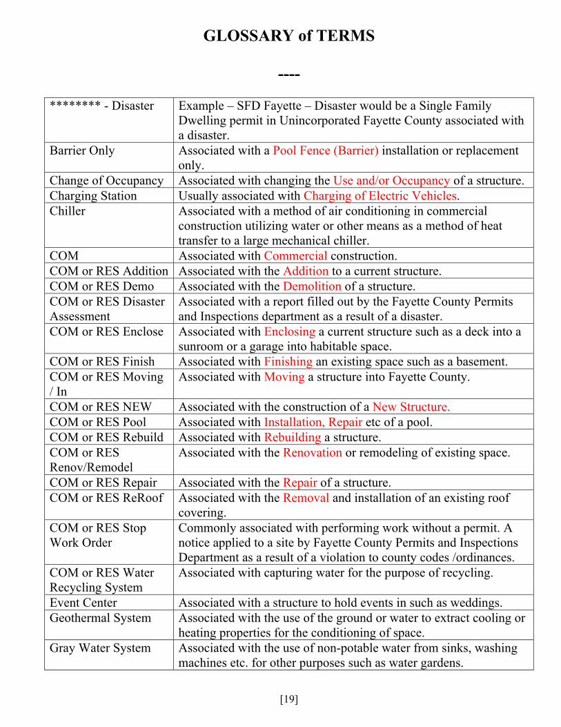
GLOSSARY of TERMS
---- ******** - Disaster Example – SFD Fayette – Disaster would be a Single Family
Dwelling permit in Unincorporated Fayette County associated with a disaster.
Barrier Only Associated with a Pool Fence (Barrier) installation or replacement only.
Change of Occupancy Associated with changing the Use and/or Occupancy of a structure. Charging Station Usually associated with Charging of Electric Vehicles. Chiller Associated with a method of air conditioning in commercial
construction utilizing water or other means as a method of heat transfer to a large mechanical chiller.
COM Associated with Commercial construction. COM or RES Addition Associated with the Addition to a current structure. COM or RES Demo Associated with the Demolition of a structure. COM or RES Disaster Assessment
Associated with a report filled out by the Fayette County Permits and Inspections department as a result of a disaster.
COM or RES Enclose Associated with Enclosing a current structure such as a deck into a sunroom or a garage into habitable space.
COM or RES Finish Associated with Finishing an existing space such as a basement. COM or RES Moving / In
Associated with Moving a structure into Fayette County.
COM or RES NEW Associated with the construction of a New Structure. COM or RES Pool Associated with Installation, Repair etc of a pool. COM or RES Rebuild Associated with Rebuilding a structure. COM or RES Renov/Remodel
Associated with the Renovation or remodeling of existing space.
COM or RES Repair Associated with the Repair of a structure. COM or RES ReRoof Associated with the Removal and installation of an existing roof
covering. COM or RES Stop Work Order
Commonly associated with performing work without a permit. A notice applied to a site by Fayette County Permits and Inspections Department as a result of a violation to county codes /ordinances.
COM or RES Water Recycling System
Associated with capturing water for the purpose of recycling.
Event Center Associated with a structure to hold events in such as weddings. Geothermal System Associated with the use of the ground or water to extract cooling or
heating properties for the conditioning of space. Gray Water System Associated with the use of non-potable water from sinks, washing
machines etc. for other purposes such as water gardens.
[20]
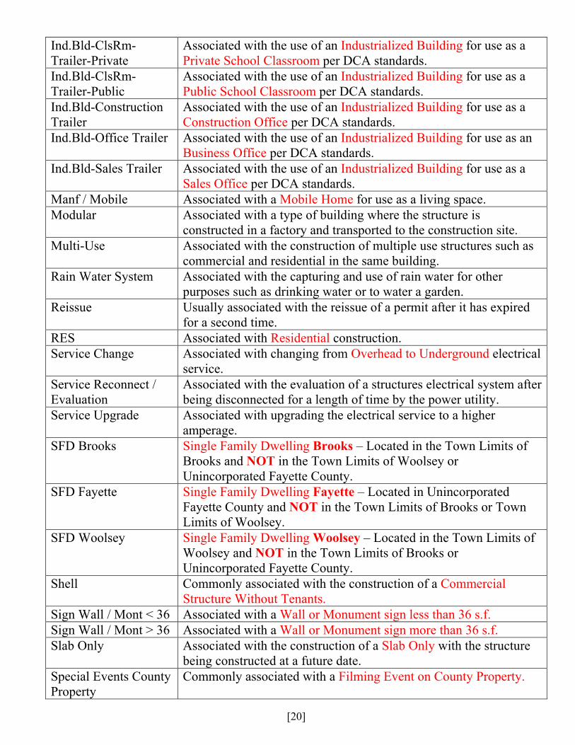
Ind.Bld-ClsRm-Trailer-Private
Associated with the use of an Industrialized Building for use as a Private School Classroom per DCA standards.
Ind.Bld-ClsRm-Trailer-Public
Associated with the use of an Industrialized Building for use as a Public School Classroom per DCA standards.
Ind.Bld-Construction Trailer
Associated with the use of an Industrialized Building for use as a Construction Office per DCA standards.
Ind.Bld-Office Trailer Associated with the use of an Industrialized Building for use as an Business Office per DCA standards.
Ind.Bld-Sales Trailer Associated with the use of an Industrialized Building for use as a Sales Office per DCA standards.
Manf / Mobile Associated with a Mobile Home for use as a living space. Modular Associated with a type of building where the structure is
constructed in a factory and transported to the construction site. Multi-Use Associated with the construction of multiple use structures such as
commercial and residential in the same building. Rain Water System Associated with the capturing and use of rain water for other
purposes such as drinking water or to water a garden. Reissue Usually associated with the reissue of a permit after it has expired
for a second time. RES Associated with Residential construction. Service Change Associated with changing from Overhead to Underground electrical
service. Service Reconnect / Evaluation
Associated with the evaluation of a structures electrical system after being disconnected for a length of time by the power utility.
Service Upgrade Associated with upgrading the electrical service to a higher amperage.
SFD Brooks Single Family Dwelling Brooks – Located in the Town Limits of Brooks and NOT in the Town Limits of Woolsey or Unincorporated Fayette County.
SFD Fayette Single Family Dwelling Fayette – Located in Unincorporated Fayette County and NOT in the Town Limits of Brooks or Town Limits of Woolsey.
SFD Woolsey Single Family Dwelling Woolsey – Located in the Town Limits of Woolsey and NOT in the Town Limits of Brooks or Unincorporated Fayette County.
Shell Commonly associated with the construction of a Commercial Structure Without Tenants.
Sign Wall / Mont < 36 Associated with a Wall or Monument sign less than 36 s.f. Sign Wall / Mont > 36 Associated with a Wall or Monument sign more than 36 s.f. Slab Only Associated with the construction of a Slab Only with the structure
being constructed at a future date. Special Events County Property
Commonly associated with a Filming Event on County Property.
[21]
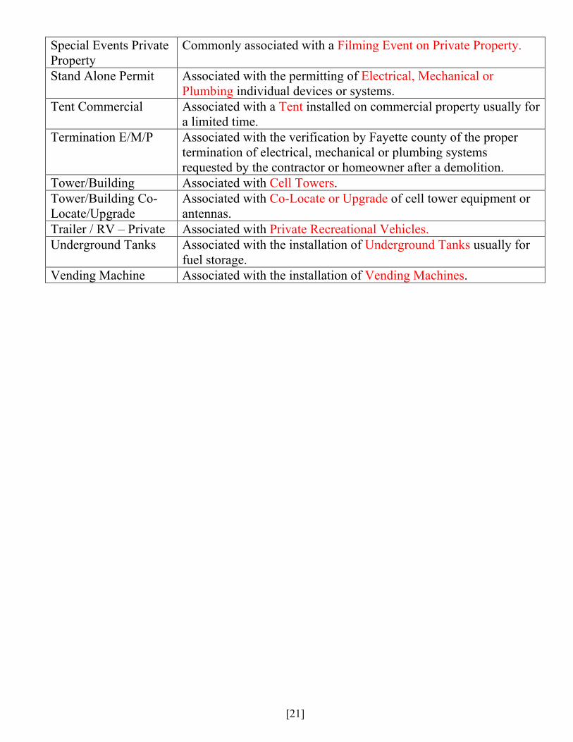
Special Events Private Property
Commonly associated with a Filming Event on Private Property.
Stand Alone Permit Associated with the permitting of Electrical, Mechanical or Plumbing individual devices or systems.
Tent Commercial Associated with a Tent installed on commercial property usually for a limited time.
Termination E/M/P Associated with the verification by Fayette county of the proper termination of electrical, mechanical or plumbing systems requested by the contractor or homeowner after a demolition.
Tower/Building Associated with Cell Towers. Tower/Building Co-Locate/Upgrade
Associated with Co-Locate or Upgrade of cell tower equipment or antennas.
Trailer / RV – Private Associated with Private Recreational Vehicles. Underground Tanks Associated with the installation of Underground Tanks usually for
fuel storage. Vending Machine Associated with the installation of Vending Machines.