Embed Size (px)
Citation preview
7/27/2019 Electrosurgery KLS Principals
http://slidepdf.com/reader/full/electrosurgery-kls-principals 1/36
Electrosurgery
Manual
7/27/2019 Electrosurgery KLS Principals
http://slidepdf.com/reader/full/electrosurgery-kls-principals 2/36
1 Electrophysical principles
2 V 1.1
The company Gebrüder Martin GmbH & Co. KG has been actively engaged in the production ofelectrosurgical equipment since 1960. The high frequency generators developed and manufac-tured since that time have established a reputation for Martin as a competent supplier amongstusers in all areas of specialist surgery. At Martin, the technological development of equipmenthas been an ongoing process. Recent examples of this are provided by such procedures asbipolar cutting, electrode detection, or application monitoring by means of a divided rubberneutral electrode. Generator design has undergone far-reaching changes in the decades since1960. Today, with the dynamic output control of the generator, Martin places a facility in thehands of the operator that, to the greatest possible extent, automates HF generator operation.
This manual is the latest in the illustration series that is available from Martin. You can contactus via our sales representatives.
The manual is organised under the following chapters:
1 Electrophysical principles
2 Application techniques
3 Risks
4 Product information
Something of the history
2800 BC
First reference to the use of heat as a healing medium in the earliest known book onsurgery the Edwin Smith papyrus.
Heating the instruments by fire and flammable gases
Middle of the 19th century
Heating instruments externally superseded by the discovery of the ability of electriccurrent to heat a metallic conductor when flowing through it.
First application of electric current in surgical techniques
Use of galvano-cautery: a red hot platinum wire
Technical forerunner of the HF unit
7/27/2019 Electrosurgery KLS Principals
http://slidepdf.com/reader/full/electrosurgery-kls-principals 3/36
1 Electrophysical principles
V 1.1 3
The working principle of electrosurgery
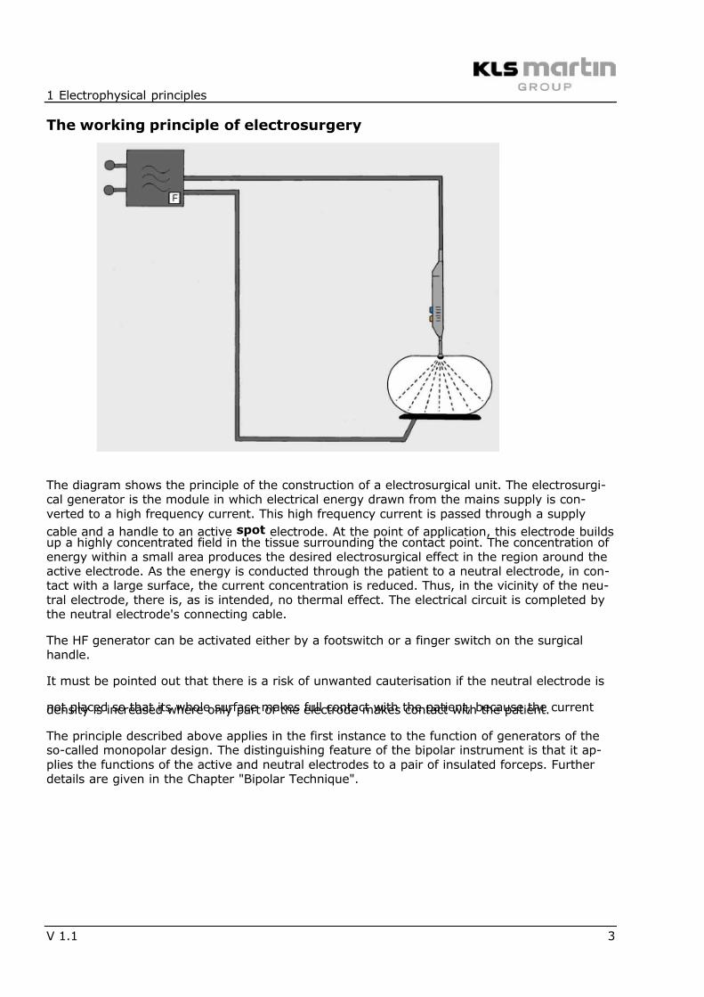
The diagram shows the principle of the construction of a electrosurgical unit. The electrosurgi-cal generator is the module in which electrical energy drawn from the mains supply is con-verted to a high frequency current. This high frequency current is passed through a supply
cable and a handle to an active spot electrode. At the point of application, this electrode buildsup a highly concentrated field in the tissue surrounding the contact point. The concentration ofenergy within a small area produces the desired electrosurgical effect in the region around theactive electrode. As the energy is conducted through the patient to a neutral electrode, in con-tact with a large surface, the current concentration is reduced. Thus, in the vicinity of the neu-tral electrode, there is, as is intended, no thermal effect. The electrical circuit is completed bythe neutral electrode's connecting cable.
The HF generator can be activated either by a footswitch or a finger switch on the surgicalhandle.
It must be pointed out that there is a risk of unwanted cauterisation if the neutral electrode is
not placed so that its whole surface makes full contact with the patient, because the currentdensity is increased where only part of the electrode makes contact with the patient.
The principle described above applies in the first instance to the function of generators of theso-called monopolar design. The distinguishing feature of the bipolar instrument is that it ap-plies the functions of the active and neutral electrodes to a pair of insulated forceps. Furtherdetails are given in the Chapter "Bipolar Technique".
7/27/2019 Electrosurgery KLS Principals
http://slidepdf.com/reader/full/electrosurgery-kls-principals 4/36
1 Electrophysical principles
4 V 1.1
Stimulus effect
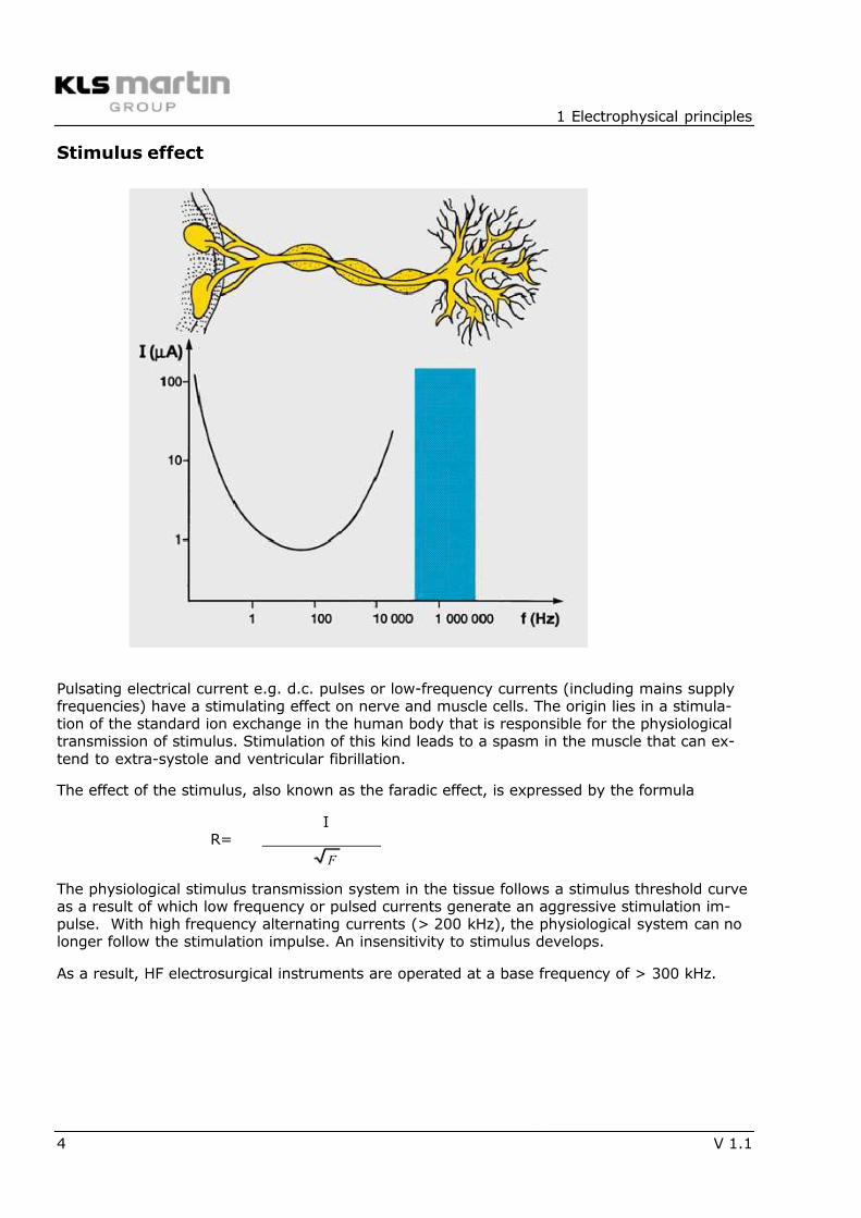
Pulsating electrical current e.g. d.c. pulses or low-frequency currents (including mains supplyfrequencies) have a stimulating effect on nerve and muscle cells. The origin lies in a stimula-tion of the standard ion exchange in the human body that is responsible for the physiologicaltransmission of stimulus. Stimulation of this kind leads to a spasm in the muscle that can ex-tend to extra-systole and ventricular fibrillation.
The effect of the stimulus, also known as the faradic effect, is expressed by the formula
IR= _____________
F
The physiological stimulus transmission system in the tissue follows a stimulus threshold curveas a result of which low frequency or pulsed currents generate an aggressive stimulation im-pulse. With high frequency alternating currents (> 200 kHz), the physiological system can nolonger follow the stimulation impulse. An insensitivity to stimulus develops.
As a result, HF electrosurgical instruments are operated at a base frequency of > 300 kHz.
7/27/2019 Electrosurgery KLS Principals
http://slidepdf.com/reader/full/electrosurgery-kls-principals 5/36
1 Electrophysical principles
V 1.1 5
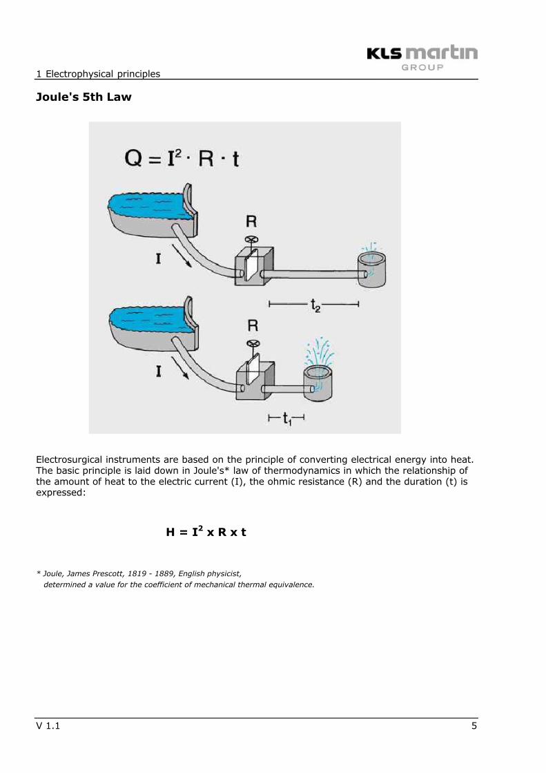
Joule's 5th Law
Electrosurgical instruments are based on the principle of converting electrical energy into heat.The basic principle is laid down in Joule's* law of thermodynamics in which the relationship ofthe amount of heat to the electric current (I), the ohmic resistance (R) and the duration (t) isexpressed:
H = I2 x R x t
* Joule, James Prescott, 1819 - 1889, English physicist,
determined a value for the coefficient of mechanical thermal equivalence.
7/27/2019 Electrosurgery KLS Principals
http://slidepdf.com/reader/full/electrosurgery-kls-principals 6/36
1 Electrophysical principles
6 V 1.1
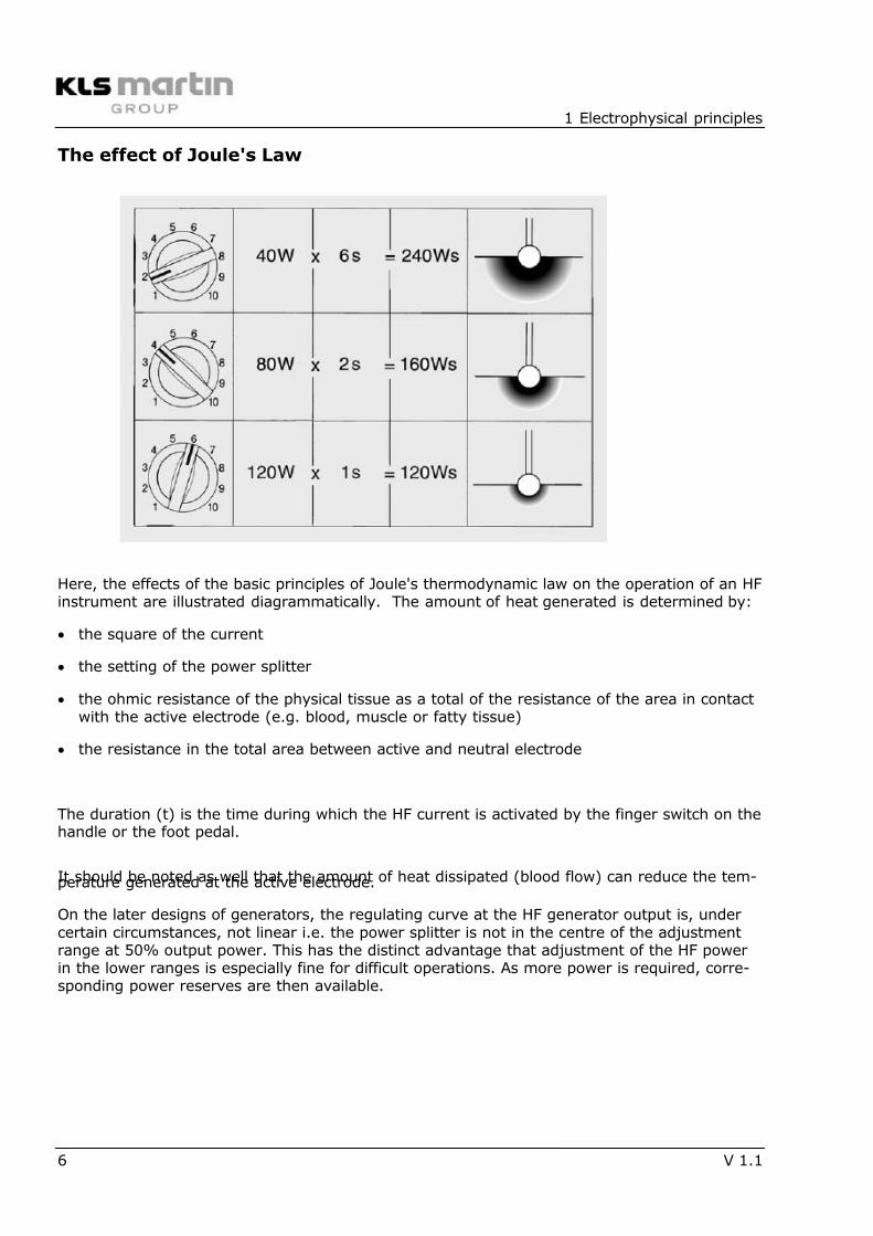
The effect of Joule's Law
Here, the effects of the basic principles of Joule's thermodynamic law on the operation of an HFinstrument are illustrated diagrammatically. The amount of heat generated is determined by:
• the square of the current
• the setting of the power splitter
• the ohmic resistance of the physical tissue as a total of the resistance of the area in contactwith the active electrode (e.g. blood, muscle or fatty tissue)
• the resistance in the total area between active and neutral electrode
The duration (t) is the time during which the HF current is activated by the finger switch on thehandle or the foot pedal.
It should be noted as well that the amount of heat dissipated (blood flow) can reduce the tem-perature generated at the active electrode.
On the later designs of generators, the regulating curve at the HF generator output is, undercertain circumstances, not linear i.e. the power splitter is not in the centre of the adjustmentrange at 50% output power. This has the distinct advantage that adjustment of the HF powerin the lower ranges is especially fine for difficult operations. As more power is required, corre-sponding power reserves are then available.
7/27/2019 Electrosurgery KLS Principals
http://slidepdf.com/reader/full/electrosurgery-kls-principals 7/36
1 Electrophysical principles
V 1.1 7
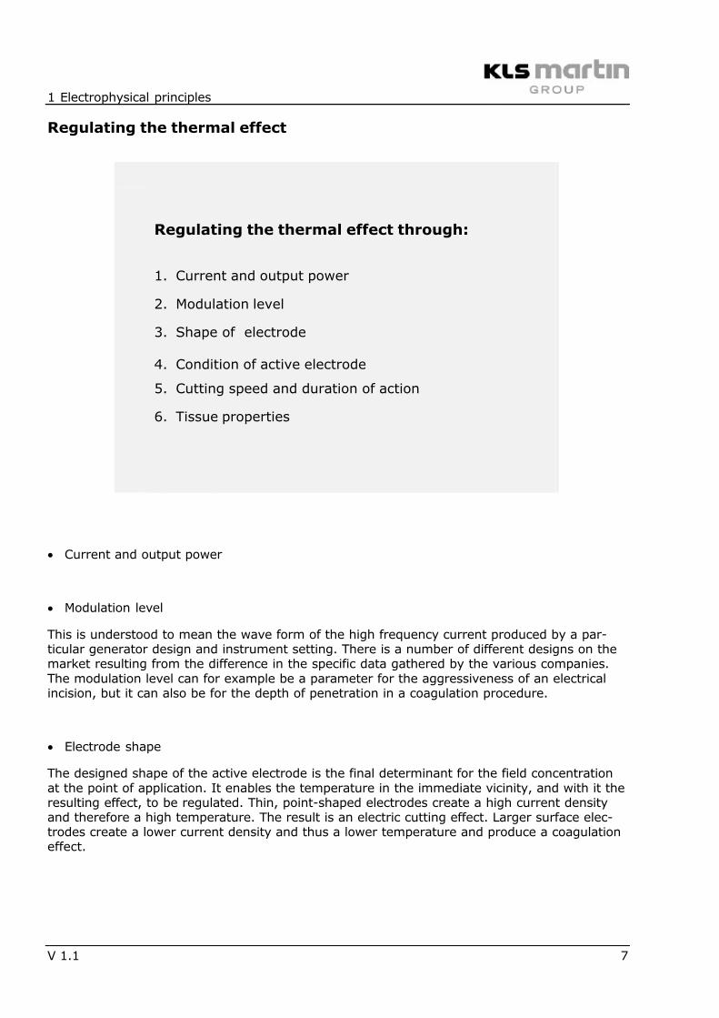
Regulating the thermal effect
Regulating the thermal effect through:
1. Current and output power
2. Modulation level
3. Shape of electrode
4. Condition of active electrode
5. Cutting speed and duration of action
6. Tissue properties
• Current and output power
• Modulation level
This is understood to mean the wave form of the high frequency current produced by a par-ticular generator design and instrument setting. There is a number of different designs on themarket resulting from the difference in the specific data gathered by the various companies.The modulation level can for example be a parameter for the aggressiveness of an electricalincision, but it can also be for the depth of penetration in a coagulation procedure.
• Electrode shape
The designed shape of the active electrode is the final determinant for the field concentrationat the point of application. It enables the temperature in the immediate vicinity, and with it theresulting effect, to be regulated. Thin, point-shaped electrodes create a high current densityand therefore a high temperature. The result is an electric cutting effect. Larger surface elec-trodes create a lower current density and thus a lower temperature and produce a coagulationeffect.
7/27/2019 Electrosurgery KLS Principals
http://slidepdf.com/reader/full/electrosurgery-kls-principals 8/36
1 Electrophysical principles
8 V 1.1
• Condition of the electrode
According to Joule's law of thermodynamics, the effects are proportional to resistance. In addi-tion to the physical resistance already described, the electrode contact resistance, i.e. an elec-
trode on which coagulate has already formed, increases the resistance of the system enor-mously. With an unchanged instrument setting and unchanged time, the resulting effect willtherefore be considerably reduced. This being so, a contaminated electrode must always becleaned during the course of the procedure.
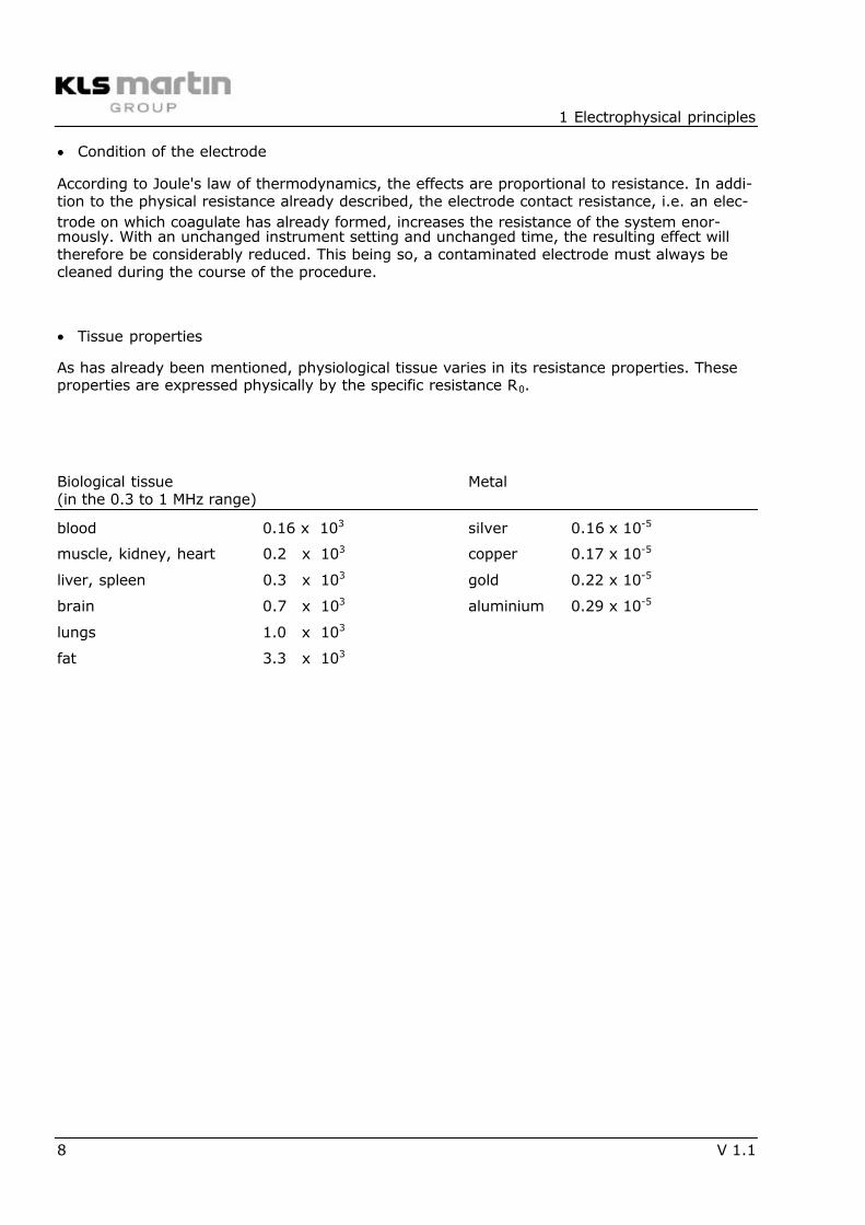
• Tissue properties
As has already been mentioned, physiological tissue varies in its resistance properties. Theseproperties are expressed physically by the specific resistance R0.
Biological tissue Metal(in the 0.3 to 1 MHz range)
blood 0.16 x 10³ silver 0.16 x 10⁻⁵
muscle, kidney, heart 0.2 x 10³ copper 0.17 x 10⁻⁵
liver, spleen 0.3 x 10³ gold 0.22 x 10⁻⁵
brain 0.7 x 10³ aluminium 0.29 x 10⁻⁵
lungs 1.0 x 10³
fat 3.3 x 10³
7/27/2019 Electrosurgery KLS Principals
http://slidepdf.com/reader/full/electrosurgery-kls-principals 9/36
1 Electrophysical principles
V 1.1 9
The effect of the current
Temperatures above 45°C cause a breakdown in the structure of living tissue and disruption ofthe function of protein molecules. The process is referred to as denaturisation. The origin is athermal effect. Depending upon the type of temperature range and the wave form employed,we differentiate between two types of HF current effect.
• Coagulation
Temperatures of 60 – 70°C in the area around the active electrode lead to a slow boiling of theintra-cellular fluid through the cell membrane. As a result of this effect, the cell shrinks andseveral cells link up to form chains. A "welding effect" is initiated which stops the bleeding.
•
ElectrotomyTemperatures of above 100°C in the region around the active electrode lead to the rapidevaporation of the fluid within the cell membrane. As a result, the cell membrane rupturesforming vapour around the electrode which in turn involves other cells lying in the path of theelectrode as it moves. Electrotomy thus cannot be compared to a mechanical cutting process.
• Mixed currents
The basic effects of coagulation and electrotomy can now be combined into so-called mixedcurrents, that have different characteristics. The instrument thus provides such facilities asreduced haemorrhage incision, or cutting with intense scab formation. These facilities can beselected with function keys on the control panel of the instrument.
7/27/2019 Electrosurgery KLS Principals
http://slidepdf.com/reader/full/electrosurgery-kls-principals 10/36
2 Application techniques
10 V 1.1
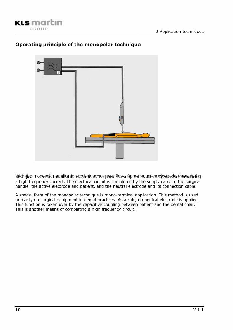
Operating principle of the monopolar technique
With the monopolar application technique, current flows from the active electrode through thebiological tissue to the neutral electrode. The power is supplied by the HF generator producinga high frequency current. The electrical circuit is completed by the supply cable to the surgicalhandle, the active electrode and patient, and the neutral electrode and its connection cable.
A special form of the monopolar technique is mono-terminal application. This method is usedprimarily on surgical equipment in dental practices. As a rule, no neutral electrode is applied.This function is taken over by the capacitive coupling between patient and the dental chair.This is another means of completing a high frequency circuit.
7/27/2019 Electrosurgery KLS Principals
http://slidepdf.com/reader/full/electrosurgery-kls-principals 11/36
2 Application techniques
V 1.1 11
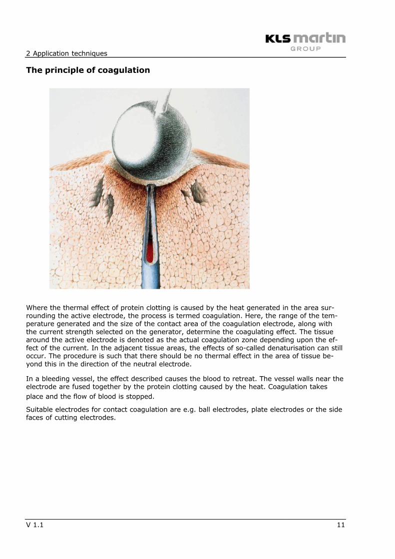
The principle of coagulation
Where the thermal effect of protein clotting is caused by the heat generated in the area sur-rounding the active electrode, the process is termed coagulation. Here, the range of the tem-perature generated and the size of the contact area of the coagulation electrode, along withthe current strength selected on the generator, determine the coagulating effect. The tissuearound the active electrode is denoted as the actual coagulation zone depending upon the ef-fect of the current. In the adjacent tissue areas, the effects of so-called denaturisation can stilloccur. The procedure is such that there should be no thermal effect in the area of tissue be-yond this in the direction of the neutral electrode.
In a bleeding vessel, the effect described causes the blood to retreat. The vessel walls near theelectrode are fused together by the protein clotting caused by the heat. Coagulation takes
place and the flow of blood is stopped.
Suitable electrodes for contact coagulation are e.g. ball electrodes, plate electrodes or the sidefaces of cutting electrodes.
7/27/2019 Electrosurgery KLS Principals
http://slidepdf.com/reader/full/electrosurgery-kls-principals 12/36
2 Application techniques
12 V 1.1
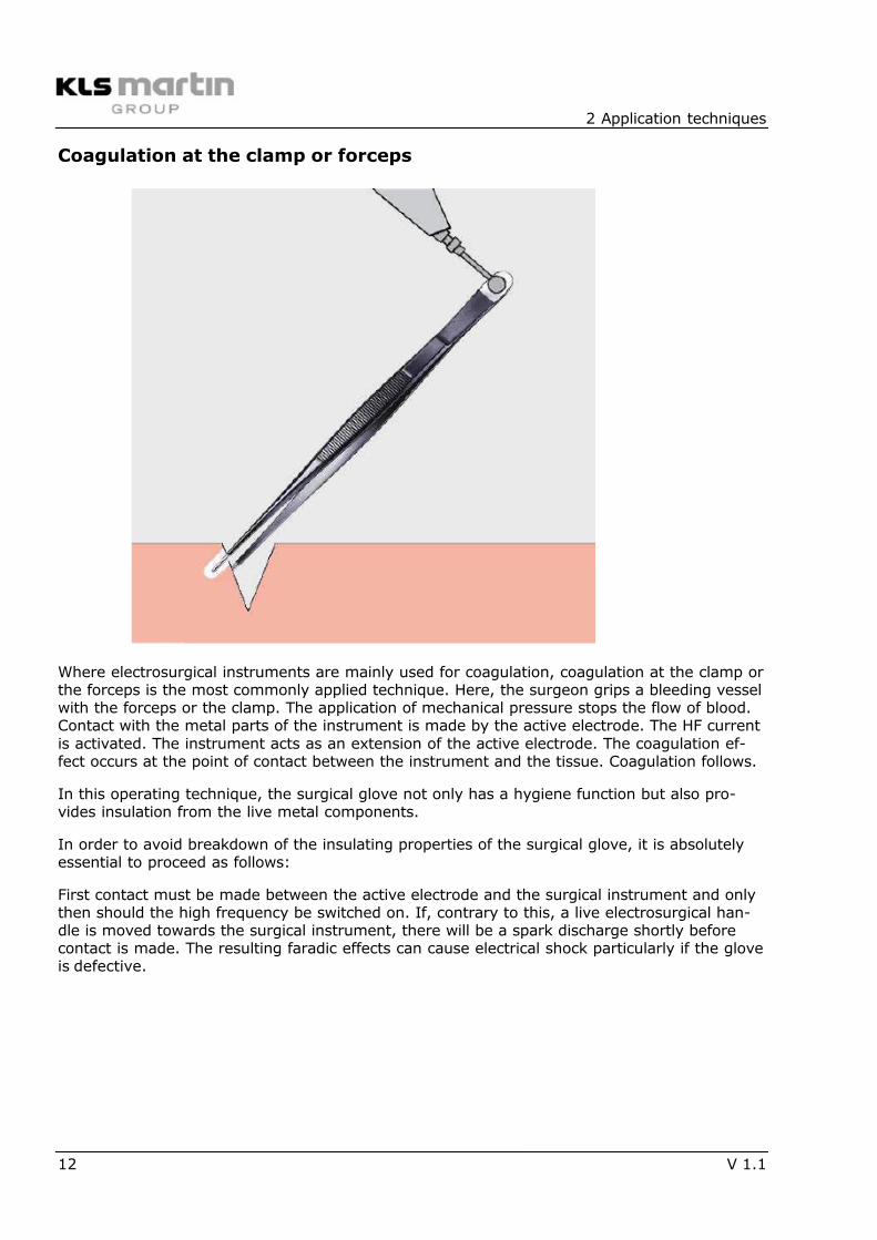
Coagulation at the clamp or forceps
Where electrosurgical instruments are mainly used for coagulation, coagulation at the clamp orthe forceps is the most commonly applied technique. Here, the surgeon grips a bleeding vesselwith the forceps or the clamp. The application of mechanical pressure stops the flow of blood.Contact with the metal parts of the instrument is made by the active electrode. The HF currentis activated. The instrument acts as an extension of the active electrode. The coagulation ef-fect occurs at the point of contact between the instrument and the tissue. Coagulation follows.
In this operating technique, the surgical glove not only has a hygiene function but also pro-vides insulation from the live metal components.
In order to avoid breakdown of the insulating properties of the surgical glove, it is absolutelyessential to proceed as follows:
First contact must be made between the active electrode and the surgical instrument and onlythen should the high frequency be switched on. If, contrary to this, a live electrosurgical han-dle is moved towards the surgical instrument, there will be a spark discharge shortly beforecontact is made. The resulting faradic effects can cause electrical shock particularly if the gloveis defective.
7/27/2019 Electrosurgery KLS Principals
http://slidepdf.com/reader/full/electrosurgery-kls-principals 13/36
2 Application techniques
V 1.1 13
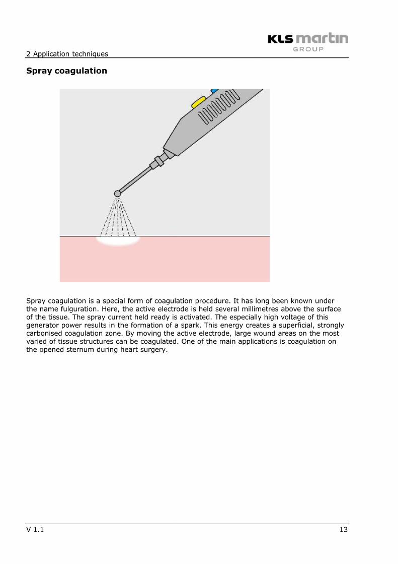
Spray coagulation
Spray coagulation is a special form of coagulation procedure. It has long been known underthe name fulguration. Here, the active electrode is held several millimetres above the surfaceof the tissue. The spray current held ready is activated. The especially high voltage of thisgenerator power results in the formation of a spark. This energy creates a superficial, stronglycarbonised coagulation zone. By moving the active electrode, large wound areas on the mostvaried of tissue structures can be coagulated. One of the main applications is coagulation onthe opened sternum during heart surgery.
7/27/2019 Electrosurgery KLS Principals
http://slidepdf.com/reader/full/electrosurgery-kls-principals 14/36
2 Application techniques
14 V 1.1
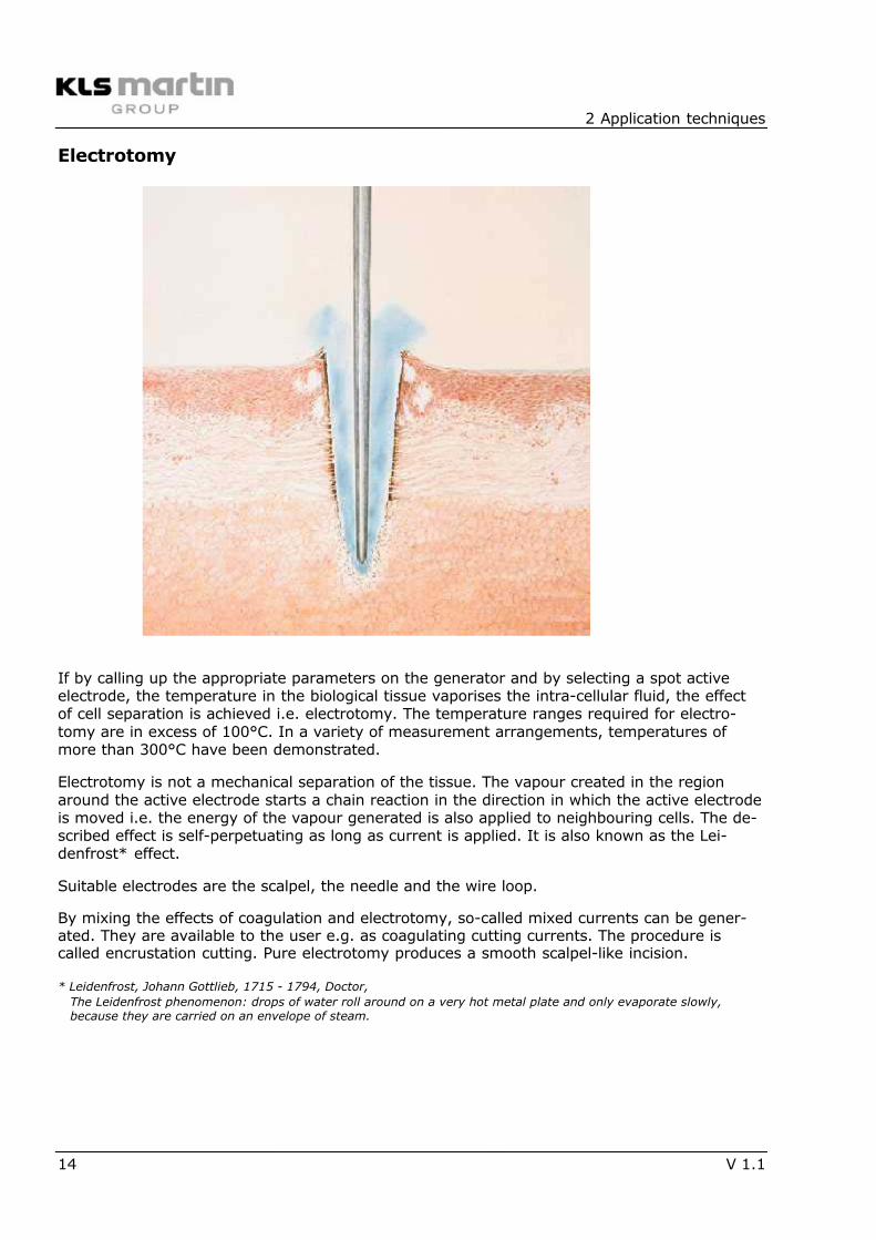
Electrotomy
If by calling up the appropriate parameters on the generator and by selecting a spot activeelectrode, the temperature in the biological tissue vaporises the intra-cellular fluid, the effectof cell separation is achieved i.e. electrotomy. The temperature ranges required for electro-tomy are in excess of 100°C. In a variety of measurement arrangements, temperatures ofmore than 300°C have been demonstrated.
Electrotomy is not a mechanical separation of the tissue. The vapour created in the regionaround the active electrode starts a chain reaction in the direction in which the active electrodeis moved i.e. the energy of the vapour generated is also applied to neighbouring cells. The de-scribed effect is self-perpetuating as long as current is applied. It is also known as the Lei-denfrost* effect.
Suitable electrodes are the scalpel, the needle and the wire loop.
By mixing the effects of coagulation and electrotomy, so-called mixed currents can be gener-ated. They are available to the user e.g. as coagulating cutting currents. The procedure iscalled encrustation cutting. Pure electrotomy produces a smooth scalpel-like incision.
* Leidenfrost, Johann Gottlieb, 1715 - 1794, Doctor,
The Leidenfrost phenomenon: drops of water roll around on a very hot metal plate and only evaporate slowly,because they are carried on an envelope of steam.
7/27/2019 Electrosurgery KLS Principals
http://slidepdf.com/reader/full/electrosurgery-kls-principals 15/36
2 Application techniques
V 1.1 15
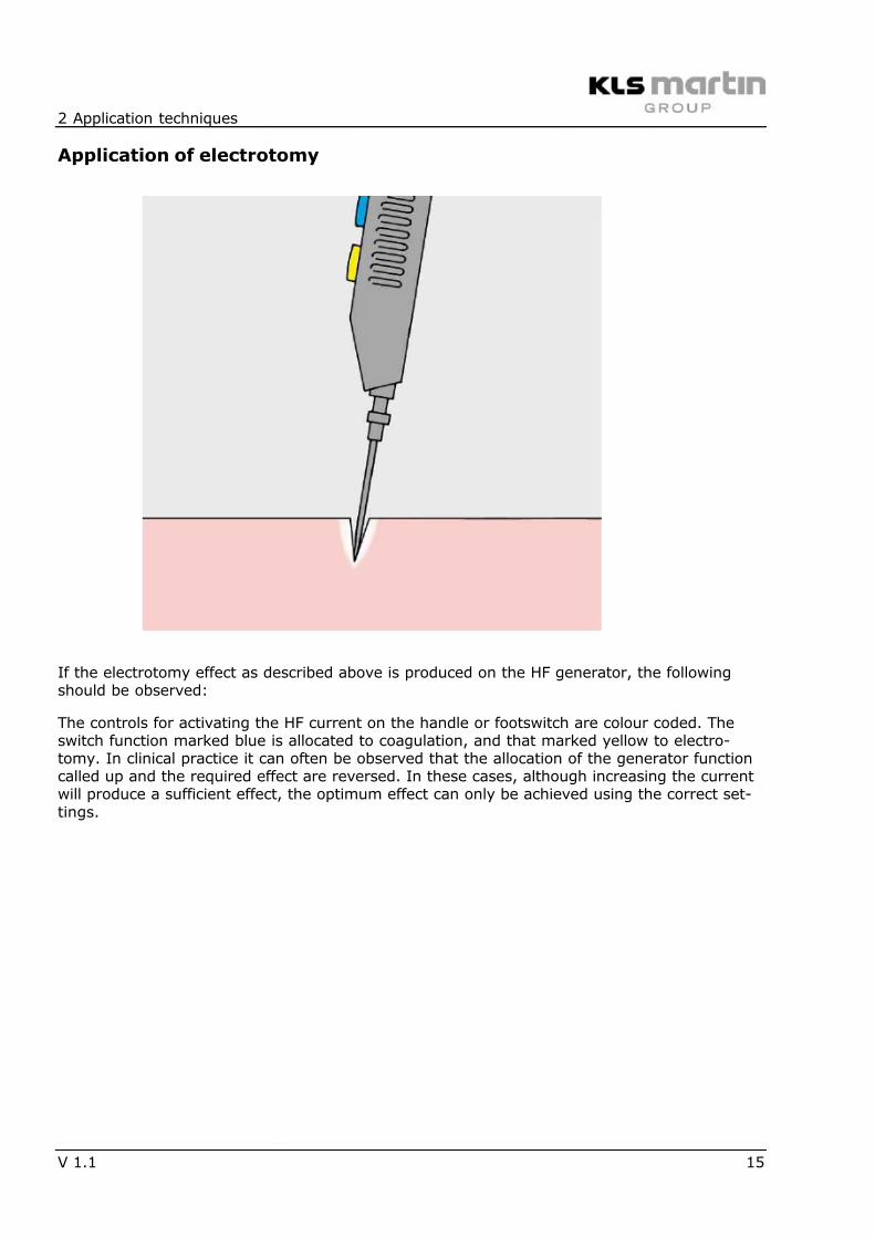
Application of electrotomy
If the electrotomy effect as described above is produced on the HF generator, the followingshould be observed:
The controls for activating the HF current on the handle or footswitch are colour coded. Theswitch function marked blue is allocated to coagulation, and that marked yellow to electro-tomy. In clinical practice it can often be observed that the allocation of the generator functioncalled up and the required effect are reversed. In these cases, although increasing the currentwill produce a sufficient effect, the optimum effect can only be achieved using the correct set-tings.
7/27/2019 Electrosurgery KLS Principals
http://slidepdf.com/reader/full/electrosurgery-kls-principals 16/36
2 Application techniques
16 V 1.1
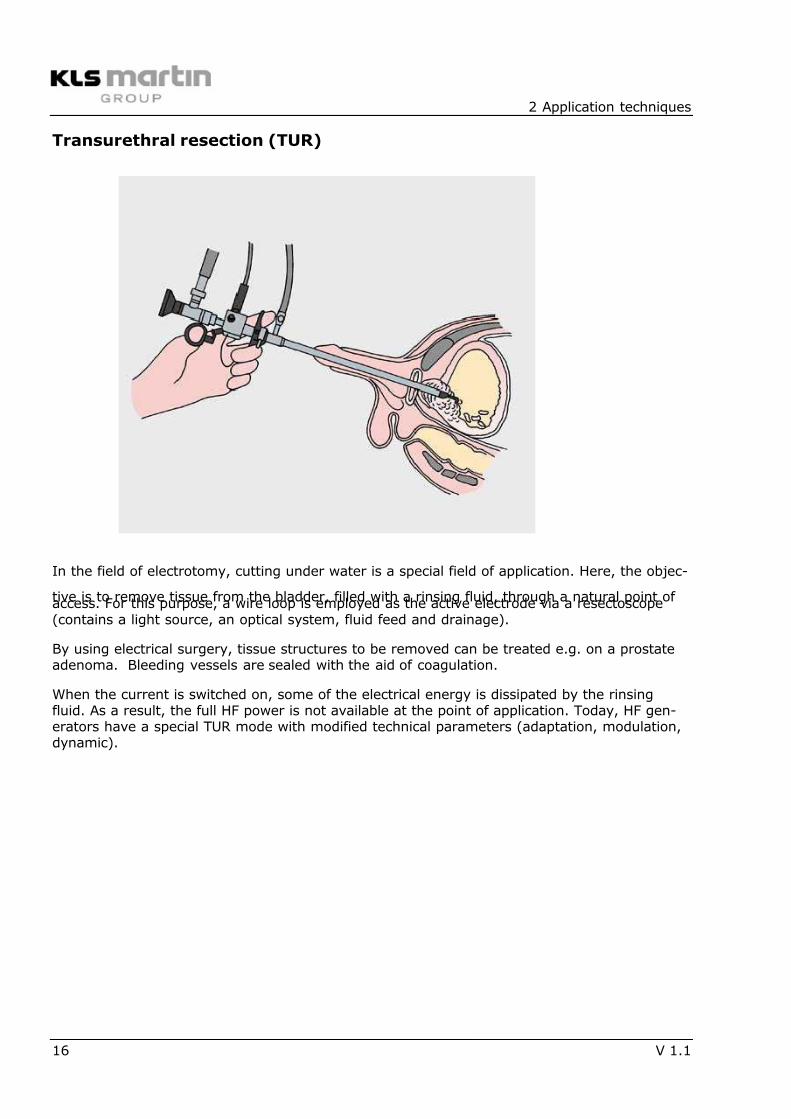
Transurethral resection (TUR)
In the field of electrotomy, cutting under water is a special field of application. Here, the objec-
tive is to remove tissue from the bladder, filled with a rinsing fluid, through a natural point ofaccess. For this purpose, a wire loop is employed as the active electrode via a resectoscope(contains a light source, an optical system, fluid feed and drainage).
By using electrical surgery, tissue structures to be removed can be treated e.g. on a prostateadenoma. Bleeding vessels are sealed with the aid of coagulation.
When the current is switched on, some of the electrical energy is dissipated by the rinsingfluid. As a result, the full HF power is not available at the point of application. Today, HF gen-erators have a special TUR mode with modified technical parameters (adaptation, modulation,dynamic).
7/27/2019 Electrosurgery KLS Principals
http://slidepdf.com/reader/full/electrosurgery-kls-principals 17/36
2 Application techniques
V 1.1 17
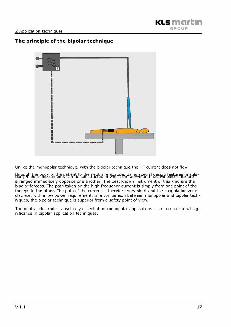
The principle of the bipolar technique
Unlike the monopolar technique, with the bipolar technique the HF current does not flow
through the body of the patient to the neutral electrode. Using special design features (insula-tion), bipolar instruments can be constructed in which the active and neutral electrodes arearranged immediately opposite one another. The best known instrument of this kind are thebipolar forceps. The path taken by the high frequency current is simply from one point of theforceps to the other. The path of the current is therefore very short and the coagulation zonediscrete, with a low power requirement. In a comparison between monopolar and bipolar tech-niques, the bipolar technique is superior from a safety point of view.
The neutral electrode - absolutely essential for monopolar applications - is of no functional sig-nificance in bipolar application techniques.
7/27/2019 Electrosurgery KLS Principals
http://slidepdf.com/reader/full/electrosurgery-kls-principals 18/36
2 Application techniques
18 V 1.1
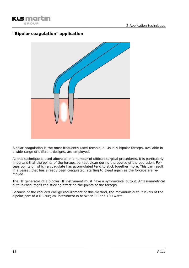
“Bipolar coagulation” application
Bipolar coagulation is the most frequently used technique. Usually bipolar forceps, available ina wide range of different designs, are employed.
As this technique is used above all in a number of difficult surgical procedures, it is particularlyimportant that the points of the forceps be kept clean during the course of the operation. For-ceps points on which a coagulate has accumulated tend to stick together more. This can resultin a vessel, that has already been coagulated, starting to bleed again as the forceps are re-moved.
The HF generator of a bipolar HF instrument must have a symmetrical output. An asymmetricaloutput encourages the sticking effect on the points of the forceps.
Because of the reduced energy requirement of this method, the maximum output levels of thebipolar part of a HF surgical instrument is between 80 and 100 watts.
7/27/2019 Electrosurgery KLS Principals
http://slidepdf.com/reader/full/electrosurgery-kls-principals 19/36
2 Application techniques
V 1.1 19
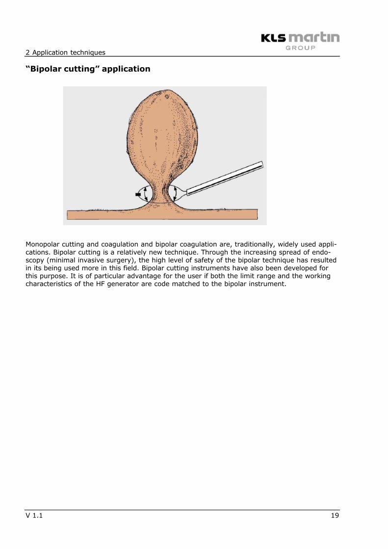
“Bipolar cutting” application
Monopolar cutting and coagulation and bipolar coagulation are, traditionally, widely used appli-cations. Bipolar cutting is a relatively new technique. Through the increasing spread of endo-scopy (minimal invasive surgery), the high level of safety of the bipolar technique has resultedin its being used more in this field. Bipolar cutting instruments have also been developed forthis purpose. It is of particular advantage for the user if both the limit range and the workingcharacteristics of the HF generator are code matched to the bipolar instrument.
7/27/2019 Electrosurgery KLS Principals
http://slidepdf.com/reader/full/electrosurgery-kls-principals 20/36
3 Risks
20 V 1.1
Risks
The use of electrosurgical equipment is associated with special risks. For this reason, HF gen-erators and accessories are listed under the "Critical equipment technology" group in the rele-vant statutory regulations. Risks to patients, operators and third parties can arise from a num-ber of possible causes. Relevant literature, accessible statistics and experience gained by com-panies show these to be:
• technical deficiency
• unwanted high frequency burning
• incorrect operation
• defective accessories
• ignition of flammable fluids and gases
• risks from improper combination with other equipment
Special mention is made in this context of the fact that patient positioning injury (decubitus) isoften erroneously referred to as high frequency burning.
It can be unequivocally stated that, when used properly and competently, electrosurgical sys-tems have proved to be reliable, safe medical systems. This is absolutely conditional upon theoperating instructions supplied with each unit being thoroughly understood.
7/27/2019 Electrosurgery KLS Principals
http://slidepdf.com/reader/full/electrosurgery-kls-principals 21/36
3 Risks
V 1.1 21
Application of the neutral electrode
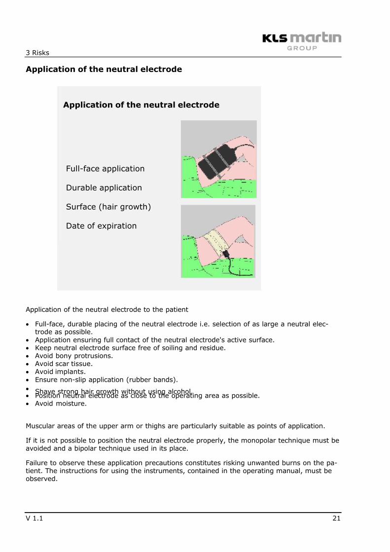
Application of the neutral electrode
Full-face application
Durable application
Surface (hair growth)
Date of expiration
Application of the neutral electrode to the patient
• Full-face, durable placing of the neutral electrode i.e. selection of as large a neutral elec-trode as possible.
• Application ensuring full contact of the neutral electrode's active surface.• Keep neutral electrode surface free of soiling and residue.• Avoid bony protrusions.• Avoid scar tissue.• Avoid implants.• Ensure non-slip application (rubber bands).• Shave strong hair growth without using alcohol.• Position neutral electrode as close to the operating area as possible.• Avoid moisture.
Muscular areas of the upper arm or thighs are particularly suitable as points of application.
If it is not possible to position the neutral electrode properly, the monopolar technique must beavoided and a bipolar technique used in its place.
Failure to observe these application precautions constitutes risking unwanted burns on the pa-tient. The instructions for using the instruments, contained in the operating manual, must beobserved.
7/27/2019 Electrosurgery KLS Principals
http://slidepdf.com/reader/full/electrosurgery-kls-principals 22/36
3 Risks
22 V 1.1
Technical safety when applying the neutral electrode
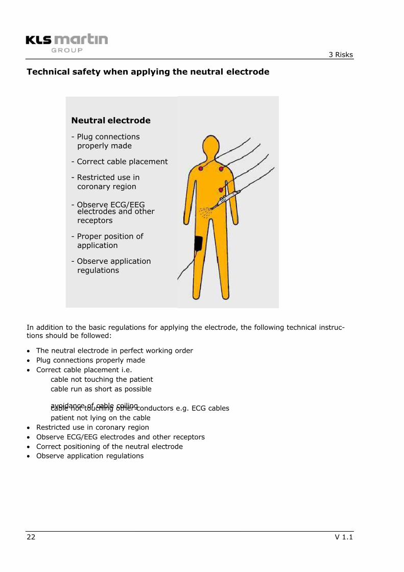
In addition to the basic regulations for applying the electrode, the following technical instruc-tions should be followed:
• The neutral electrode in perfect working order
• Plug connections properly made
• Correct cable placement i.e.cable not touching the patientcable run as short as possible
avoidance of cable coilingcable not touching other conductors e.g. ECG cablespatient not lying on the cable
• Restricted use in coronary region
• Observe ECG/EEG electrodes and other receptors• Correct positioning of the neutral electrode• Observe application regulations
Neutral electrode
- Plug connectionsproperly made
- Correct cable placement
- Restricted use incoronary region
- Observe ECG/EEGelectrodes and otherreceptors
- Proper position ofapplication
- Observe applicationregulations
7/27/2019 Electrosurgery KLS Principals
http://slidepdf.com/reader/full/electrosurgery-kls-principals 23/36
3 Risks
V 1.1 23
Types of neutral electrodes
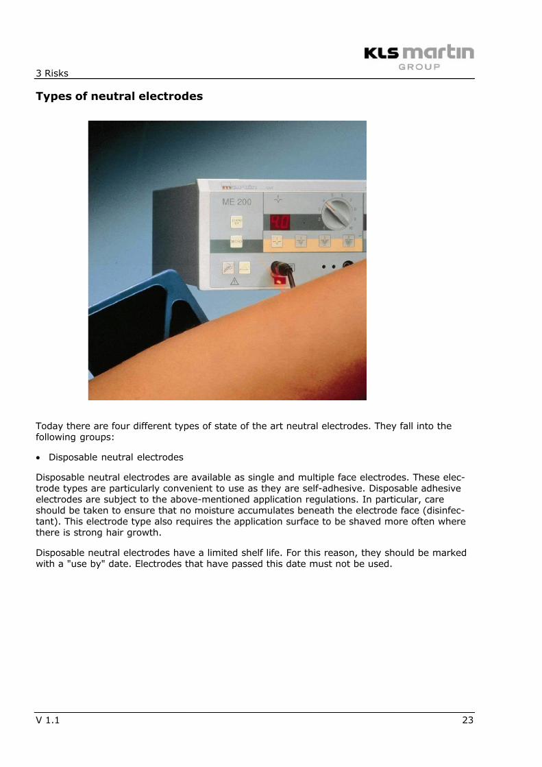
Today there are four different types of state of the art neutral electrodes. They fall into thefollowing groups:
• Disposable neutral electrodes
Disposable neutral electrodes are available as single and multiple face electrodes. These elec-trode types are particularly convenient to use as they are self-adhesive. Disposable adhesiveelectrodes are subject to the above-mentioned application regulations. In particular, careshould be taken to ensure that no moisture accumulates beneath the electrode face (disinfec-tant). This electrode type also requires the application surface to be shaved more often wherethere is strong hair growth.
Disposable neutral electrodes have a limited shelf life. For this reason, they should be markedwith a "use by" date. Electrodes that have passed this date must not be used.
7/27/2019 Electrosurgery KLS Principals
http://slidepdf.com/reader/full/electrosurgery-kls-principals 24/36
3 Risks
24 V 1.1
• Reusable neutral electrodes
Reusable neutral electrode types made of silicon rubber are now also available as single anddouble face electrodes.
The latest development in the neutral electrode sector is the twin face rubber neutral elec-trode. This electrode not only has all the features of a reusable component, it also enables ap-plication of the two faces to be monitored. Electrosurgical instruments that are equipped withthe appropriate circuitry, monitor the application resistance and thus the full application of theelectrode surface to the patient.
These electrodes must be cleaned before being reused. To restore their electrical properties,they can be steam sterilised at specific intervals, on the rubber programme setting.
7/27/2019 Electrosurgery KLS Principals
http://slidepdf.com/reader/full/electrosurgery-kls-principals 25/36
3 Risks
V 1.1 25
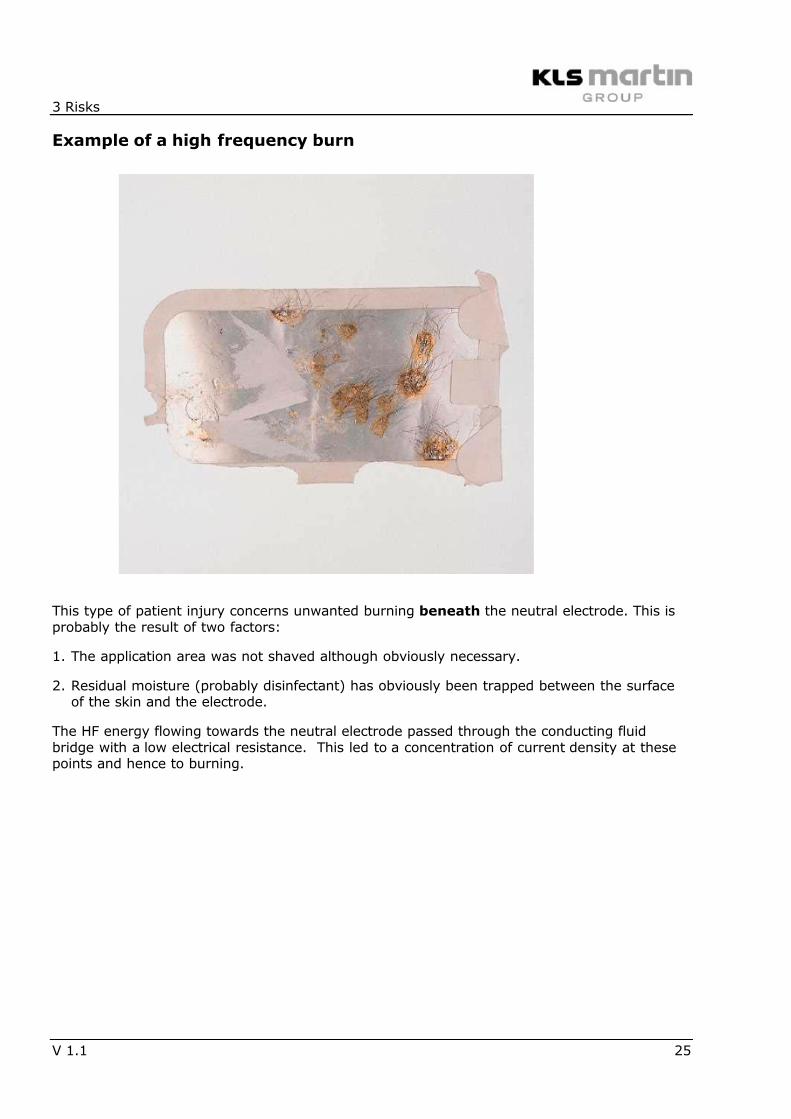
Example of a high frequency burn
This type of patient injury concerns unwanted burning beneath the neutral electrode. This isprobably the result of two factors:
1. The application area was not shaved although obviously necessary.
2. Residual moisture (probably disinfectant) has obviously been trapped between the surfaceof the skin and the electrode.
The HF energy flowing towards the neutral electrode passed through the conducting fluidbridge with a low electrical resistance. This led to a concentration of current density at thesepoints and hence to burning.
7/27/2019 Electrosurgery KLS Principals
http://slidepdf.com/reader/full/electrosurgery-kls-principals 26/36
3 Risks
26 V 1.1
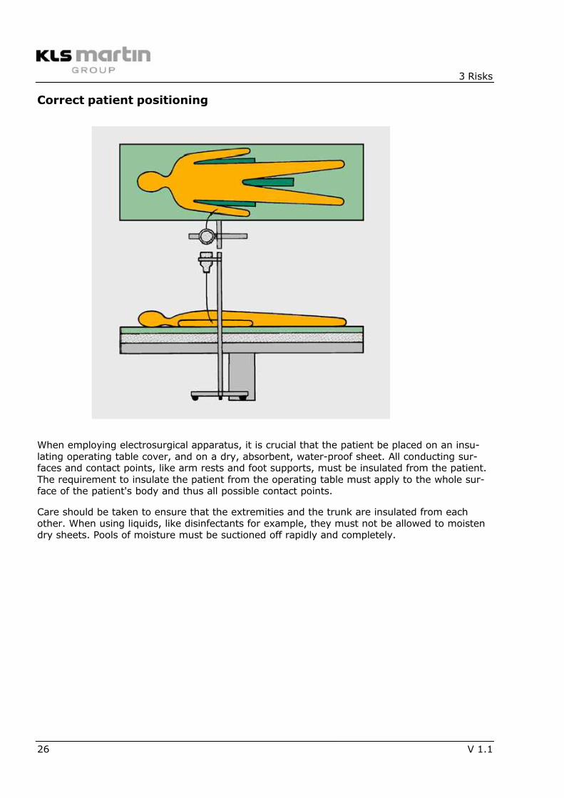
Correct patient positioning
When employing electrosurgical apparatus, it is crucial that the patient be placed on an insu-lating operating table cover, and on a dry, absorbent, water-proof sheet. All conducting sur-faces and contact points, like arm rests and foot supports, must be insulated from the patient.The requirement to insulate the patient from the operating table must apply to the whole sur-face of the patient's body and thus all possible contact points.
Care should be taken to ensure that the extremities and the trunk are insulated from eachother. When using liquids, like disinfectants for example, they must not be allowed to moistendry sheets. Pools of moisture must be suctioned off rapidly and completely.
7/27/2019 Electrosurgery KLS Principals
http://slidepdf.com/reader/full/electrosurgery-kls-principals 27/36
3 Risks
V 1.1 27
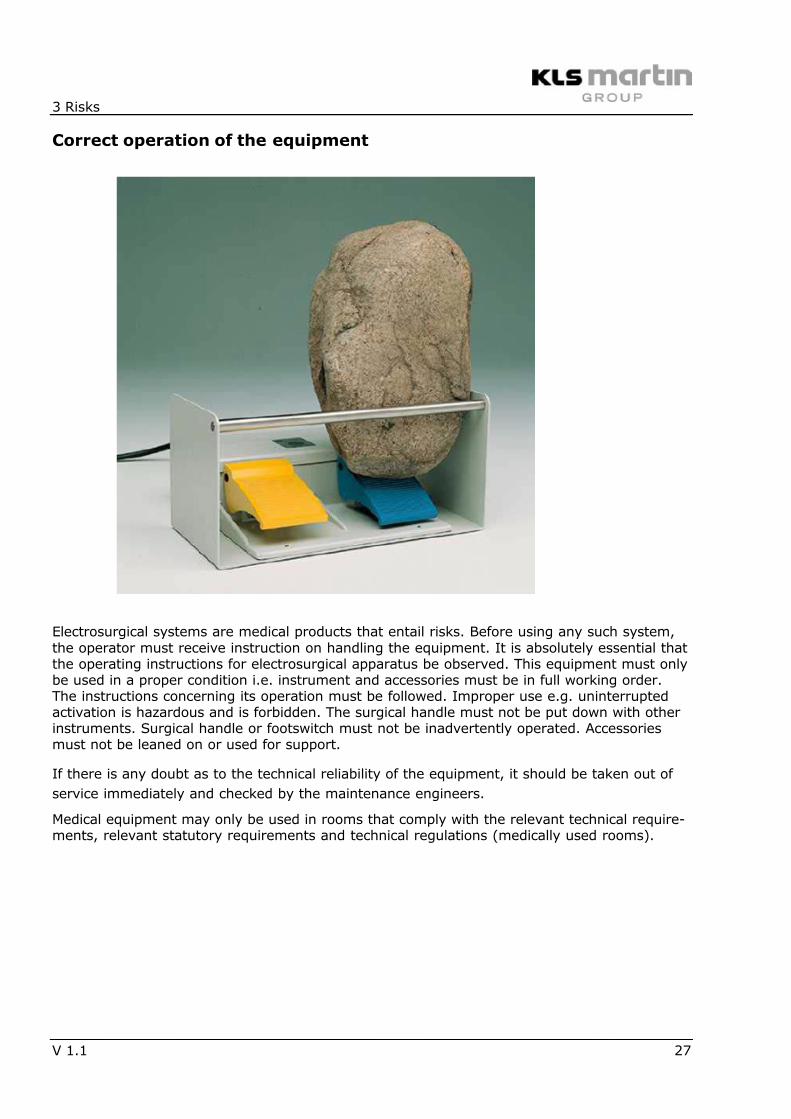
Correct operation of the equipment
Electrosurgical systems are medical products that entail risks. Before using any such system,the operator must receive instruction on handling the equipment. It is absolutely essential thatthe operating instructions for electrosurgical apparatus be observed. This equipment must onlybe used in a proper condition i.e. instrument and accessories must be in full working order.The instructions concerning its operation must be followed. Improper use e.g. uninterruptedactivation is hazardous and is forbidden. The surgical handle must not be put down with otherinstruments. Surgical handle or footswitch must not be inadvertently operated. Accessoriesmust not be leaned on or used for support.
If there is any doubt as to the technical reliability of the equipment, it should be taken out of
service immediately and checked by the maintenance engineers.
Medical equipment may only be used in rooms that comply with the relevant technical require-ments, relevant statutory requirements and technical regulations (medically used rooms).
7/27/2019 Electrosurgery KLS Principals
http://slidepdf.com/reader/full/electrosurgery-kls-principals 28/36
3 Risks
28 V 1.1
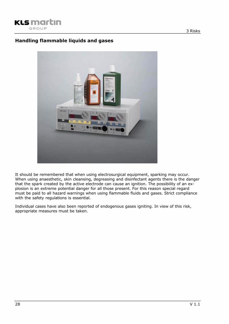
Handling flammable liquids and gases
It should be remembered that when using electrosurgical equipment, sparking may occur.When using anaesthetic, skin cleansing, degreasing and disinfectant agents there is the dangerthat the spark created by the active electrode can cause an ignition. The possibility of an ex-plosion is an extreme potential danger for all those present. For this reason special regardmust be paid to all hazard warnings when using flammable fluids and gases. Strict compliancewith the safety regulations is essential.
Individual cases have also been reported of endogenous gases igniting. In view of this risk,appropriate measures must be taken.
7/27/2019 Electrosurgery KLS Principals
http://slidepdf.com/reader/full/electrosurgery-kls-principals 29/36
3 Risks
V 1.1 29
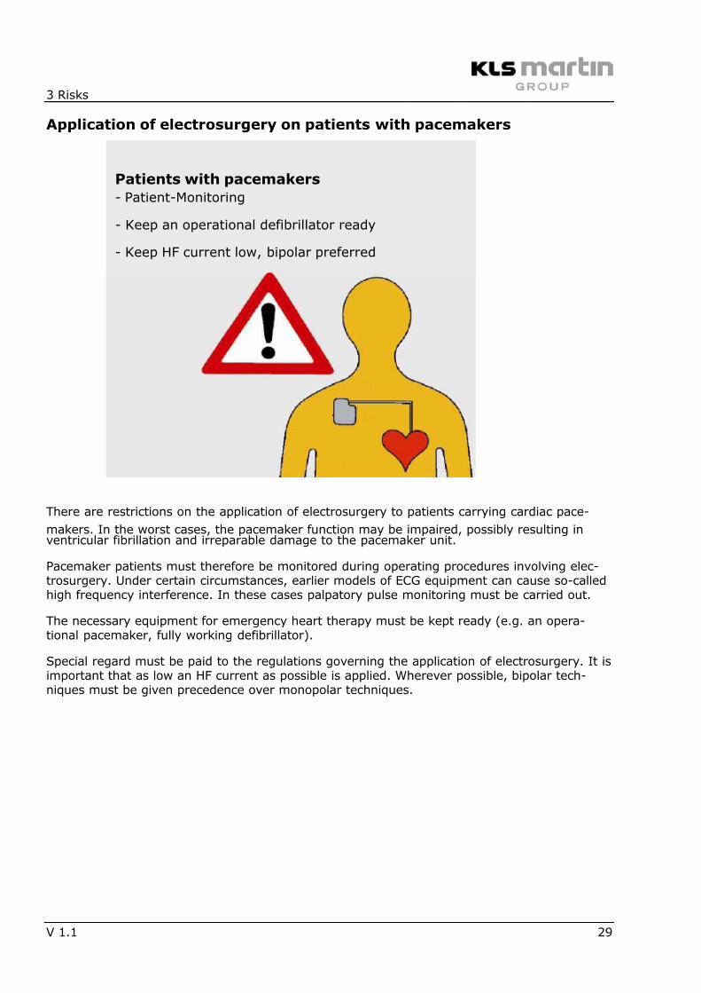
Application of electrosurgery on patients with pacemakers
There are restrictions on the application of electrosurgery to patients carrying cardiac pace-
makers. In the worst cases, the pacemaker function may be impaired, possibly resulting inventricular fibrillation and irreparable damage to the pacemaker unit.
Pacemaker patients must therefore be monitored during operating procedures involving elec-trosurgery. Under certain circumstances, earlier models of ECG equipment can cause so-calledhigh frequency interference. In these cases palpatory pulse monitoring must be carried out.
The necessary equipment for emergency heart therapy must be kept ready (e.g. an opera-tional pacemaker, fully working defibrillator).
Special regard must be paid to the regulations governing the application of electrosurgery. It isimportant that as low an HF current as possible is applied. Wherever possible, bipolar tech-niques must be given precedence over monopolar techniques.
Patients with pacemakers
- Patient-Monitoring
- Keep an operational defibrillator ready
- Keep HF current low, bipolar preferred
7/27/2019 Electrosurgery KLS Principals
http://slidepdf.com/reader/full/electrosurgery-kls-principals 30/36
3 Risks
30 V 1.1
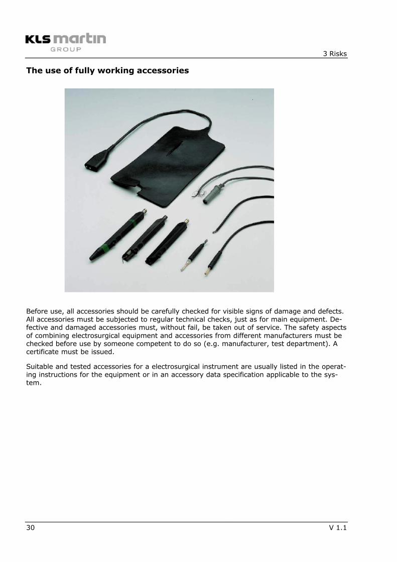
The use of fully working accessories
Before use, all accessories should be carefully checked for visible signs of damage and defects.All accessories must be subjected to regular technical checks, just as for main equipment. De-fective and damaged accessories must, without fail, be taken out of service. The safety aspectsof combining electrosurgical equipment and accessories from different manufacturers must bechecked before use by someone competent to do so (e.g. manufacturer, test department). Acertificate must be issued.
Suitable and tested accessories for a electrosurgical instrument are usually listed in the operat-ing instructions for the equipment or in an accessory data specification applicable to the sys-tem.
7/27/2019 Electrosurgery KLS Principals
http://slidepdf.com/reader/full/electrosurgery-kls-principals 31/36
4 Product information
V 1.1 31
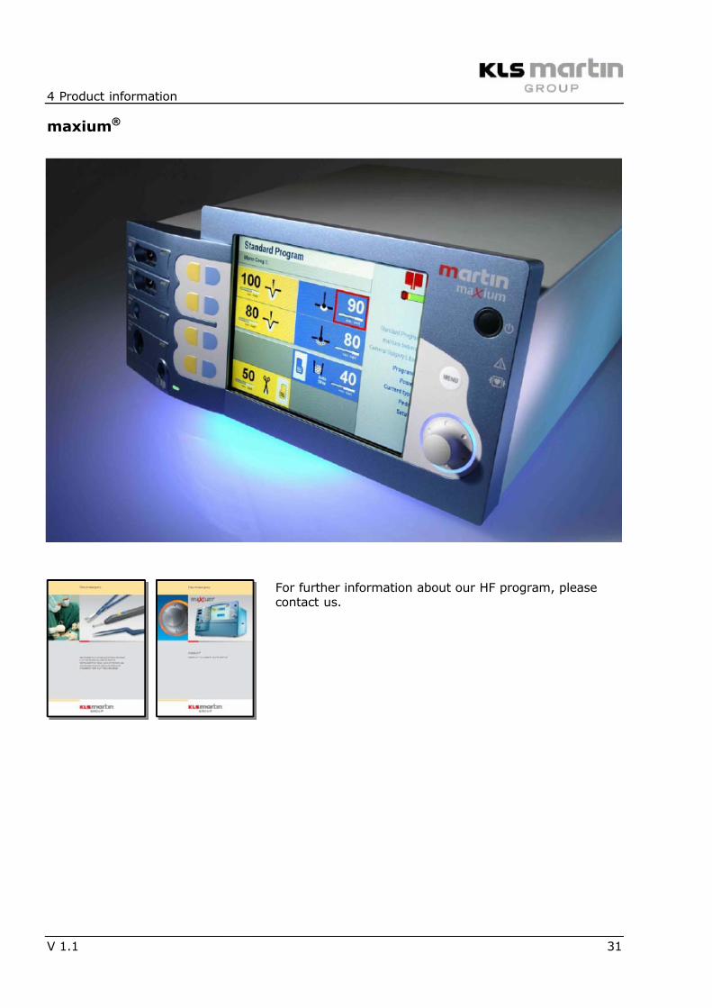
maxium®
For further information about our HF program, pleasecontact us.
7/27/2019 Electrosurgery KLS Principals
http://slidepdf.com/reader/full/electrosurgery-kls-principals 32/36
4 Product information
32 V 1.1
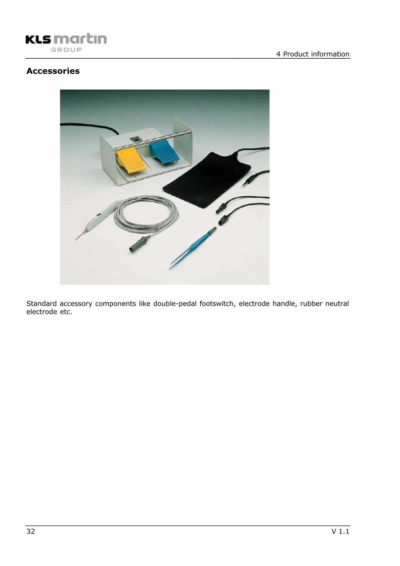
Accessories
Standard accessory components like double-pedal footswitch, electrode handle, rubber neutralelectrode etc.
7/27/2019 Electrosurgery KLS Principals
http://slidepdf.com/reader/full/electrosurgery-kls-principals 33/36
4 Product information
V 1.1 33
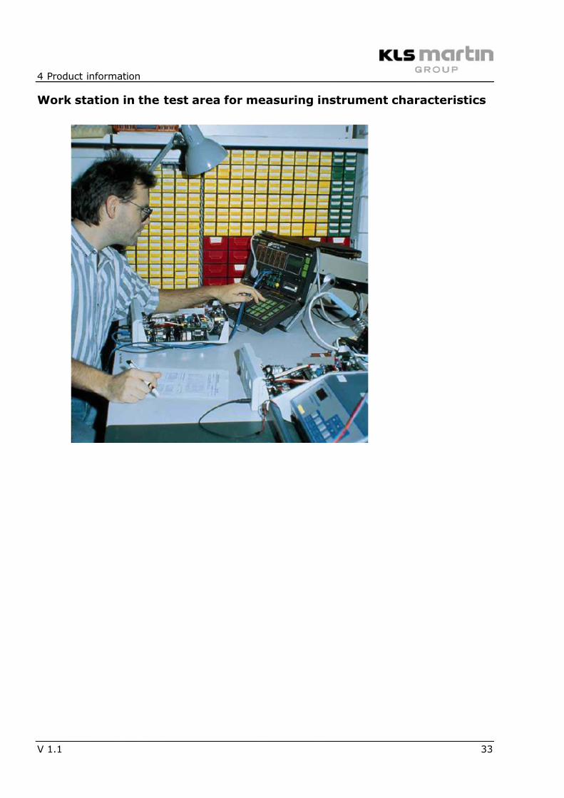
Work station in the test area for measuring instrument characteristics

7/27/2019 Electrosurgery KLS Principals
http://slidepdf.com/reader/full/electrosurgery-kls-principals 34/36
4 Product information
34 V 1.1
CE mark
CE mark with code of the Notified Body as marking of a medical product suitable for free tradewithin the EU.
0297

7/27/2019 Electrosurgery KLS Principals
http://slidepdf.com/reader/full/electrosurgery-kls-principals 35/36

7/27/2019 Electrosurgery KLS Principals
http://slidepdf.com/reader/full/electrosurgery-kls-principals 36/36
Gebrüder Martin GmbH & Co. KG
Ludwigstaler Straße 132 · D-78532 Tuttlingen
Postfach 60 · D-78501 Tuttlingen/Germany
Tel. +49 7461 706-0 · Fax +49 7461 706-193
[email protected] · www.klsmartin.com