Embed Size (px)
Citation preview

1
VULCAN DGuía rápida de instalación y programación Español
AVISO
Esta guía rápida es un resumen del manual de instalación completo. Dicho manual contiene advertencias deseguridad y otras explicaciones que deben ser tenidas en cuenta. Puede descargar el manual de instalación enel apartado “Descargas” de la web de Erreka: http://www.erreka.com/Automatismos/descargaDocumentos.aspx
�����
��
��
��
��
��
��
�
Elementos de la instalación completa
Cableado eléctricoA: Alimentación generalB: Lámpara destellante LUMIC: Fotocélulas (Rx/Tx)D: Pulsador/ selector de llaveE: AccionadorF: Antena incorporada LUMIG: Electrocerradura
MUY IMPORTANTE:
Es imprescindible instalar el tope decierre TC y los topes de apertura TAen todos los casos.
La electrocerradura es obligatoria para los accionadoressin bloqueo. Para los accionadores con bloqueo, esnecesario utilizar electrocerradura para longitudes dehoja superiores a 1,8m.
MSH
-024
/02

2
�����
�
Desbloqueo
Desbloqueo para accionamientomanual:• Abra la tapa (1).• Gire la llave de desbloqueo (2) 90º
hasta que quede perpendicular alvástago del accionador.
Bloqueo para accionamiento motorizado:• Gire la llave de desbloqueo (2) 90º
hasta que quede paralela al vástagodel accionador.
• Cierre la tapa (1).
Bloqueado Desbloqueado
�����
�
�
�
�
�����
�����
Cotas de montaje
Apertura hacia el interior
Apertura hacia el exterior
�����
Cota B
Cota A
Ángulo de apertura
130
155
80º
130
140
85º
120
140
90º
145
115
90º
125
125
95º
120
120
100º
120
105
110º
Cota B
Cota A
Ángulo de apertura
135
150
80º
125
150
85º
155
100
90º
130
130
90º
130
120
95º
135
100
100º
125
95
110º

3
�����
Nivelación
El acc ionador debe funcionarhorizontalmente : para el lo, lossoportes deben colocarse a la mismaaltura.
Compruebe la horizontalidad con unnivel.
����������
�����
�����
�����
����� �����
Montaje
7 Monte el prensaestopas e introduzcalos cables.Son necesarios 4 cables.
8 Realice las conexiones eléctricascomo se muestra en el apartadosiguiente. A continuación, coloquela tapa ( T ) y ap r i e te e lprensaestopas.
9 Ajuste las presiones de apertura ycierre, tal como se describe en lapágina siguiente. Levante la tapa(1), regule los tornillos (1) y (2) ypor último, cierre la tapa (1).
1 Monte la horquilla en elaccionador.Utilice como eje el bulón horizontalsuministrado.
2 Monte los soportes. Realice lassoldaduras con el accionadorretirado y alejado, para evitar quee l vá s tago se dañe consalpicaduras de soldadura.
3 Monte el accionador en el soportetrasero. Utilice como eje el bulón de cabezaestrecha suministrado.
����������
4 Monte el accionador en elsoporte delantero, util izandocomo eje el tornillo suministrado.
Previamente, aplique grasa en elvástago y en los orificios.
5 Monte la funda con la tapa.Fí je las mediante los torni l loscorrespondientes suministrados.
6 Afloje el tornillo de purga (P). Sit iene que desmontar e laccionador, vuelva a apretar eltornillo para evitar el derramede aceite.

4
��� ���
�� �� ��
��� ���
�� �� �
����
�� �� ��� ���
�������� ����
��� ��� �� ��� ���
���� !"#�$%&
�'()
*� *� *� *�
���'+
*� *� * *� *� *�
���� ��� ���� ���
� ���,�-
����-�./*�0*�0���1 ����-�./*�0*�0���1
����,�
� �������� ������������������� �� ����������
�� �
Conexiones eléctricas
VIVO-M201(M)
Para el accionador VULCAN D, puede emplear elcuadro de maniobra VIVO-M101(M) ó VIVO-M201(M).
Al tratarse de un equipo estacionario paraconexión permanente, debe instalarse unmedio de desconexión externo.
En caso de utilizar un sólo accionador, conécteloen las bornas G1, G2 y G3 (accionador A1).
�����
Ajuste de las presiones de apertura y cierre
Las presiones de apertura y cierre deben ajustarse en función de las dimensiones y peso de la puerta.
O No apretar los tornillos de regulación (2) y (3) hasta el tope, ya que se dañarían.
Para ambos tornillos, el giro en sentido horario aumentala presión. El giro en sentido antihorario disminuye lapresión.
Para acceder a los tornillos de ajuste, abra la tapa (1).
Presión durante la retracción del vástgo, tornillo (2):En instalaciones de apertura interior corresponde a la maniobra de apertura. En instalaciones de apertura exterior, corresponde a la maniobra de cierre.
Presión durante la extensión del vástago, tornillo (3):En instalaciones de apertura interior corresponde a la maniobra de cierre. En instalaciones de apertura exterior, corresponde a la maniobra de apertura.
Tras ajustar las presiones, cierre la tapa (1).

5
VULCAN DGuide rapide d’installation et programmation Français
AVERTISSEMENT
Ce guide rapide est un résumé du manuel d’installation complet. Ce manuel contient desavertissements de sécurité et d’autres explications qui doivent être pris en compte. Vous pouveztélécharger le manuel d’installation dans la section « Téléchargements » du site web d’Erreka : http://www.erreka.com/Automatismos/descargaDocumentos.aspx
�����
��
��
��
��
��
��
�
Éléments de l’installation complète
Câblage électriqueA : Alimentation généraleB : Feu clignotant LUMIC : Photocellules (Rx/Tx)D : Bouton-poussoir / sélecteur à cléE : ActionneurF : Antenne incorporée LUMIG : Électroserrure
TRÈS IMPORTANT :
Il est indispensable d’installer labutée de fermeture TC et les butéesd’ouverture TA dans tous les cas.
L'électroserrure est obligatoire pour les actionneurs sansblocage. Dans le cas des actionneurs avec blocage, il estnécessaire d'utiliser une électroserrure pour deslongueurs de vantail supérieures à 1,8 mètres.
MSH
-024
/01

6
�����
�
Déblocage
Déblocage pour un actionnementmanuel :• Ouvrez le couvercle (1).• Tournez la clef de déblocage (2) de
90º jusqu'à ce qu'elle resteperpendiculaire à la tige del'actionneur.
Blocage pour un actionnement motorisé :• Tournez la clef de déblocage (2) de
90º jusqu'à ce qu'elle reste parallèleà la tige de l'actionneur.
• Fermez le couvercle (1).
Bloqué Débloqué
�����
�
�
�
�
�����
�����
Cotes de montage
Ouverture vers l'intérieur
Ouverture vers l'extérieur
�����
Cote B
Cote A
Angle d'ouverture
130
155
80º
130
140
85º
120
140
90º
145
115
90º
125
125
95º
120
120
100º
120
105
110º
Cote B
Cote A
Angle d' ouverture
135
150
80º
125
150
85º
155
100
90º
130
130
90º
130
120
95º
135
100
100º
125
95
110º

7
�����
Nivellement
L’actionneur doit fonctionnerhorizontalement : pour cela, lessupports doivent être placés à la mêmehauteur.
Vérifier l’horizontalité à l’aide d’unniveau.
����������
�����
�����
�����
����� �����
Montage
7 Montez le presse-étoupe etintroduisez les câbles.4 câbles sont nécessaires.
8 Réalisez les connexionsélectriques selon les indications duparagraphe suivant. Ensuite,placez le couvercle (T) et serrez lepresse-étoupe.
9 Ajustez les pressions d'ouvertureet de fermeture, tel que cela estdécrit sur la page suivante.Soulevez le couvercle (1), réglezles vis (1) et (2), puis fermez lecouvercle (1).
1 Montez la fourche dansl'actionneur.Utilisez le boulon horizontal fournicomme un axe.
2 Montez les supports. Réalisez lessoudures avec l’actionneur retiré etéloigné pour éviter que la tige nesoit abîmée par des projections desoudure.
3 Montez l’actionneur sur le supportarrière. Utilisez le boulon à tête étroitefourni comme un axe.
����������
4 Montez l'actionneur sur lesupport avant en utilisant la visfournie comme un axe.
Appliquez préalablement de lagraisse sur la tige et dans lesorifices.
5 Montez l’étui avec le couvercle.Fixez-les avec les vis fournies.
6 Lâchez la vis de purge (P). Sivous devez démonterl’actionneur, serrez à nouveaula vis pour éviter que l’huile necoule.

8
��� ���
�� �� ��
��� ���
�� �� �
����
�� �� ��� ���
�������� ����
��� ��� �� ��� ���
���� !"#�$%&
�'()
*� *� *� *�
���'+
*� *� * *� *� *�
���� ��� ���� ���
� ���,�-
����-�./*�0*�0���1 ����-�./*�0*�0���1
����,�
� �������� ������������������� �� ����������
�� �
Connexions électriques
VIVO-M201(M)
Pour l’actionneur VULCAN D, vous pouvezemployer l’armoire de commande VIVO-M101(M)ou VIVO-M201(M).
Étant donné qu'il s'agit d'un équipementstationnaire pour une connexion permanente,il faut installer un moyen de déconnexionexterne.
Si un seul actionneur est employé, connectez-le aux bornes G1, G2 et G3 (actionneur A1).
�����
Réglage des pressions d’ouverture et de fermeture
Les pressions d'ouverture et de fermeture doivent être réglées en fonction des dimensions et du poidsde la porte.O Ne pas serrer les vis de réglage (2) et (3) jusqu’à la limite, car cela risquerait de les endommager.
Pour les deux vis, la rotation dans le sens horaireaugmente la pression. La rotation dans le sensantihoraire diminue la pression.
Pour accéder aux vis de réglage, ouvrez le couvercle (1).
Pression pendant la rétraction de la tige, vis (2) :Dans le cas des installations avec une ouverture intérieure, cela correspond à la manœuvre d'ouverture. Dans les installations avec une ouverture extérieure, cela correspond à la manœuvre de fermeture.
Pression pendant l'extension de la tige, vis (3) :Dans le cas des installations avec une ouverture intérieure, cela correspond à la manœuvre de fermeture. Dans les installations avec une ouverture extérieure, cela correspond à la manœuvre d’ouverture.
Après avoir ajusté les pressions, fermez le couvercle (1).

9
VULCAN DQuick installation and programming guide English
WARNING
This quick guide is a summary of the complete installation manual. The manual contains safety warnings andother explanations which must be taken into account. The installation manual can be downloaded by goingto the "Downloads" section of Erreka website: http://www.erreka.com/Automatismos/descargaDocumentos.aspx
�����
��
��
��
��
��
��
�
Elements of the complete installation
Electrical wiringA: Main power supplyB: LUMI Flashing lightC: Photocells (Rx/Tx)D: Pushbutton / key switchE: OperatorF: LUMI Built-in antennaG: Electrolock
VERY IMPORTANT:
The TC closing stopper and the TAopening stoppers must be installedin all cases.
The electrolock is compulsory for non-lockingoperators. For locking operators, the electrolock mustbe used for gate leaf lengths of over 1.8m.
MSH
-024
/01

10
�����
�
Unlocking
Unlocking for manual operation:• Open the cover (1).• Turn the unlocking key (2) 90º until
it is perpendicular to the operatorspindle.
Motorised operation locking:• Turn the unlocking key (2) 90º until
it is parallel to the operator spindle.• Close the cover (1).
Locked Unlocked
�����
�
�
�
�
�����
�����
Assembly levels
Inward opening
�����
Level B
Level A
Opening angle
130
155
80º
130
140
85º
120
140
90º
145
115
90º
125
125
95º
120
120
100º
120
105
110º
Level B
Level A
Opening angle
135
150
80º
125
150
85º
155
100
90º
130
130
90º
130
120
95º
135
100
100º
125
95
110º
Outward opening
11
�����
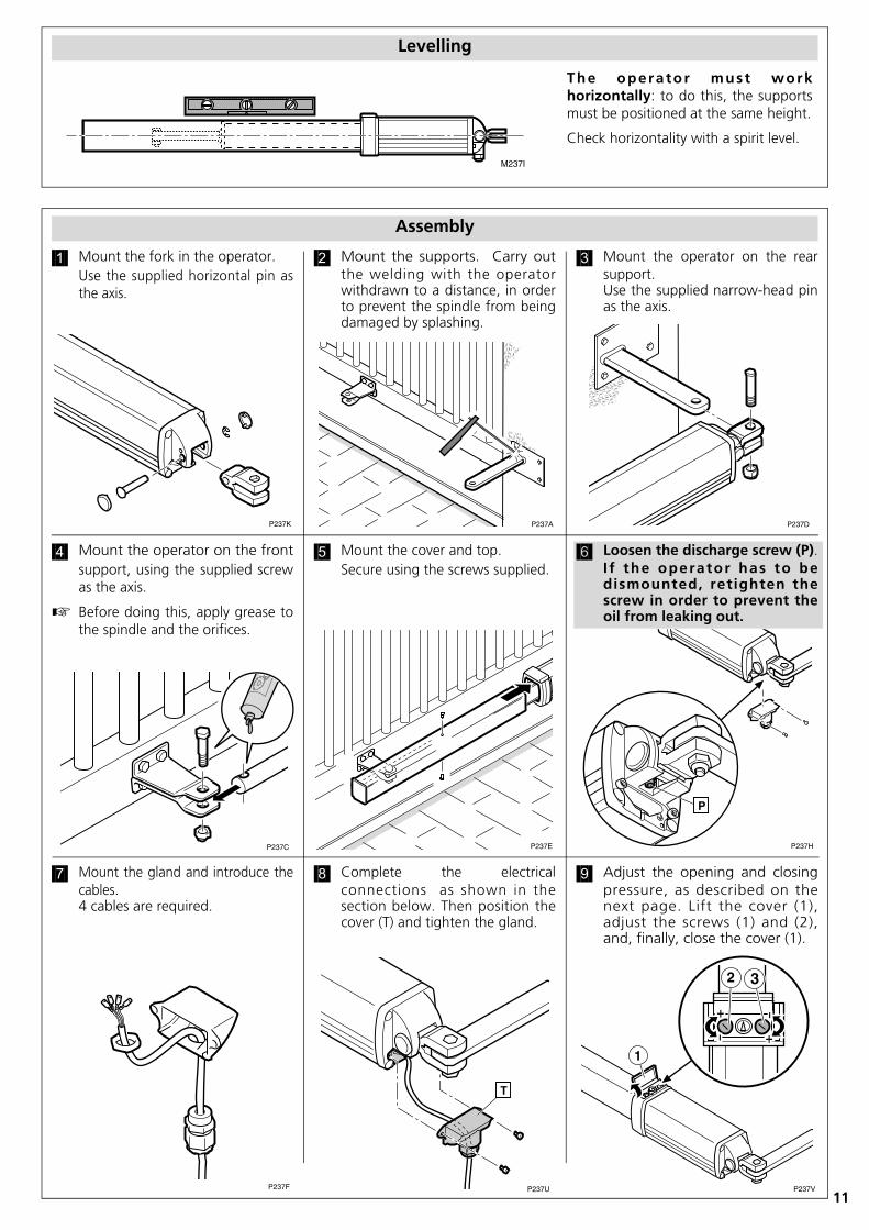
Levelling
The operator must workhorizontally: to do this, the supportsmust be positioned at the same height.
Check horizontality with a spirit level.
����������
�����
�����
�����
����� �����
Assembly
7 Mount the gland and introduce thecables.4 cables are required.
8 Complete the electricalconnections as shown in thesection below. Then position thecover (T) and tighten the gland.
9 Adjust the opening and closingpressure, as described on thenext page. Lift the cover (1),adjust the screws (1) and (2),and, finally, close the cover (1).
1 Mount the fork in the operator.Use the supplied horizontal pin asthe axis.
2 Mount the supports. Carry outthe welding with the operatorwithdrawn to a distance, in orderto prevent the spindle from beingdamaged by splashing.
3 Mount the operator on the rearsupport. Use the supplied narrow-head pinas the axis.
����������
4 Mount the operator on the frontsupport, using the supplied screwas the axis.
Before doing this, apply grease tothe spindle and the orifices.
5 Mount the cover and top.Secure using the screws supplied.
6 Loosen the discharge screw (P).I f the operator has to bedismounted, retighten thescrew in order to prevent theoil from leaking out.

12
��� ���
�� �� ��
��� ���
�� �� �
����
�� �� ��� ���
�������� ����
��� ��� �� ��� ���
���� !"#�$%&
�'()
*� *� *� *�
���'+
*� *� * *� *� *�
���� ��� ���� ���
� ���,�-
����-�./*�0*�0���1 ����-�./*�0*�0���1
����,�
� �������� ������������������� �� ����������
�� �
Electrical connections
VIVO-M201(M)
The VIVO-M101(M) or VIVO-M201(M) controlboard can be used for the VULCAN D operator.
Since this is a stationary unit for permanentconnection, an external cut-off must beinstalled.
When using a single operator, connect it tocable connectors G1, G2 and G3 (operator A1).
�����
Adjusting the opening and closing pressures
The opening and closing pressures must be adjusted in line with the size and weight of the gate.
O Do not tighten the regulation screws (2) and (3) to the maximum, as this will result in damage.
Clockwork turning increases the pressure for bothscrews. Anti-clockwork turning reduces the pressure.
The adjustment screws can be accessed by opening thecover (1).
Pressure during the retraction of the spindle, screw (2):In inward opening facilities, it corresponds to the opening operation. In outward opening facilities, it corresponds to the closing operation.
Pressure during the extension of the spindle, screw (3):In inward opening facilities, it corresponds to the closing operation. In outward opening facilities, it corresponds to the opening operation.
After adjusting the pressures, close the cover (1).

13
VULCAN DGuia rápido de instalação e programação Português
AVISO
Este guia rápido é um resumo do manual de instalação completo. Este manual contém advertências desegurança e outras explicações a ter em atenção. Pode efectuar o download do manual de instalação nasecção “Downloads” do site da Erreka: http://www.erreka.com/Automatismos/descargaDocumentos.aspx
�����
��
��
��
��
��
��
�
Elementos da instalação completa
Cablagem eléctricaA: Alimentação geralB: Lâmpada de sinalização LUMIC: Fotocélulas (Rx/Tx)D: Botão de pressão / selector de chaveE: AccionadorF: Antena incorporada LUMIG: Electrofechadura
MUITO IMPORTANTE:
É imprescindível instalar o batente de fecho TC e os batentes de abertura TA em todos os casos.
A electrofechadura é obrigatória para os accionadoressem bloqueio. Para os accionadores com bloqueio énecessário utilizar electrofechadura para comprimentosde folha superiores a 1,8 m.
MSH
-024
/01

14
�����
�
Desbloqueio
Desbloqueio para accionamentomanual:• Abra a tampa (1).• Gire a chave de desbloqueio (2) em
90º até ficar perpendicular à hastedo êmbolo do accionador.
Bloqueio para accionamento motorizado:• Gire a chave de desbloqueio (2) em
90º até ficar paralela à haste doêmbolo do accionador.
• Feche a tampa (1).
Bloqueado Desbloqueado
�
�
�����
�����
Cotas de montagem
Abertura para o interior
�����
�����
�
�
Cota B
Cota A
Ângulo de abertura
130
155
80º
130
140
85º
120
140
90º
145
115
90º
125
125
95º
120
120
100º
120
105
110º
Cota B
Cota A
Ângulo de abertura
135
150
80º
125
150
85º
155
100
90º
130
130
90º
130
120
95º
135
100
100º
125
95
110º
Abertura para o exterior
15
�����
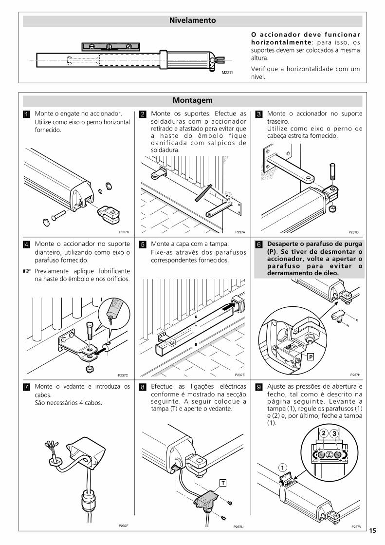
Nivelamento
O acc ionador deve func ionarhorizontalmente : para i sso, ossuportes devem ser colocados à mesmaaltura.
Verifique a horizontalidade com umnível.
�����
����������
�����
�����
�����
����� �����
Montagem
7 Monte o vedante e introduza oscabos.São necessários 4 cabos.
8 Efectue as ligações eléctricasconforme é mostrado na secçãoseguinte. A seguir coloque atampa (T) e aperte o vedante.
9 Ajuste as pressões de abertura efecho, tal como é descrito napágina seguinte. Levante atampa (1), regule os parafusos (1)e (2) e, por último, feche a tampa(1).
�����
4 Monte o accionador no suportedianteiro, utilizando como eixo oparafuso fornecido.
Previamente aplique lubrificantena haste do êmbolo e nos orifícios.
5 Monte a capa com a tampa.Fixe-as através dos parafusoscorrespondentes fornecidos.
6 Desaperte o parafuso de purga(P). Se tiver de desmontar oaccionador, volte a apertar oparafuso para ev i tar oderramamento de óleo.
1 Monte o engate no accionador.Utilize como eixo o perno horizontalfornecido.
2 Monte os suportes. Efectue assoldaduras com o accionadorretirado e afastado para evitar quea has te do êmbo lo f i quedan i f i cada com sa lp i co s desoldadura.
3 Monte o accionador no suportetraseiro. Uti l ize como eixo o perno decabeça estreita fornecido.

16
��� ���
�� �� ��
��� ���
�� �� �
����
�� �� ��� ���
�������� ����
��� ��� �� ��� ���
���� !"#�$%&
�'()
*� *� *� *�
���'+
*� *� * *� *� *�
���� ��� ���� ���
� ���,�-
����-�./*�0*�0���1 ����-�./*�0*�0���1
����,�
� �������� ������������������� �� ����������
�� �
Ligações eléctricas
VIVO-M201(M)
Para o accionador VULCAN D pode utilizar oquadro de manobra VIVO-M101(M) ou VIVO-M201(M).
Ao tratar-se de um equipamento estacionáriopara ligação permanente, deve instalar-se ummeio de desligação externo.
No caso de utilizar um único accionador, ligue-o nos bornes G1, G2 e G3 (accionador A1).
�����
Ajuste das pressões de abertura e fecho
As pressões de abertura e fecho devem ser ajustadas em função das dimensões e peso da porta.
O Não apertar os parafusos de regulação (2) e (3) até ao topo, caso contrário ficam danificados.
Para ambos os parafusos, a rotação no sentido horárioaumenta a pressão. A rotação no sentido anti-horáriodiminui a pressão.
Para aceder aos parafusos de ajuste abra a tampa (1).
Pressão durante a retracção da haste do êmbolo, parafuso (2):Em instalações de abertura interior corresponde à manobra de abertura. Em instalações de abertura exterior corresponde à manobra de fecho.
Pressão durante a extensão da haste do êmbolo, parafuso (3):Em instalações de abertura interior corresponde à manobra de fecho. Em instalações de abertura exterior corresponde à manobra de abertura.
Depois de ajustar as pressões feche a tampa (1).

17
VULCAN DKurzführer Installation und Programmierung Deutsch
HINWEIS
Dieser Kurzführer ist eine Zusammenfassung der kompletten Montageanleitung. Diese enthältSicherheitshinweise und andere Erläuterungen, die beachtet werden müssen. Die Montageanleitung kann aufder Erreka-Website unter „Downloads“ heruntergeladen werden: http://www.erreka.com/Automatismos/descargaDocumentos.aspx
�����
��
��
��
��
��
��
�
Elemente der kompletten Anlage
StromkabelA: HauptstromversorgungB: Blinklampe LUMIC: Lichtschranke (Rx/Tx)D: Drucktaster/ SchlüsseltasterE: AntriebF: Eingebaute Antenne LUMIG: Elektroschloss
WICHTIGER HINWEIS:
Es müssen in a l len Fä l lenunbedingt der Schließanschlag TCund die Öffnungsanschläge TAinstalliert werden.
Bei Antrieben ohne Verriegelung ist das ElektroschlossPflicht. Bei Antrieben mit Verriegelung muss fürTorlängen über 1,80m ein Elektroschloss verwendetwerden.
MSH
-024
/01

18
�����
�
Entriegelung
Entriegelung für manuelle Betätigung:• Öffnen Sie die Abdeckung (1).• Drehen Sie den Entriegelungsschlüssel
(2) um 90º, bis er lotrecht zumAntriebsschaft steht.
Verriegelung für motorischen Antrieb:• Drehen Sie den Entriegelungsschlüssel
(2) um 90º, bis er parallel zumAntriebsschaft steht.
• Schließen Sie die Abdeckung (1).
Verriegelt Entriegelt
�
�
�����
�����
Montagemaße
Öffnung nach Innen
�����
�����
�
�
Maß B
Maß A
Öffnungs- winkel
130
155
80º
130
140
85º
120
140
90º
145
115
90º
125
125
95º
120
120
100º
120
105
110º
Maß B
Maß A
Öffnungs- winkel
135
150
80º
125
150
85º
155
100
90º
130
130
90º
130
120
95º
135
100
100º
125
95
110º
Öffnung nach Außen

19
�����
Nivellierung
Der Antr ieb muss hor izonta lbetrieben werden: Hierfür werden dieHa l te rungen au f g l e i che r Höheangebracht.
Prüfen Sie die Horizontalität anhandeiner Wasserwaage.
�����
�����
�����
����������
�����
����� �����
Montage
7 Montieren Sie die Kabel-verschraubung und führen Sie dieKabel ein.Es sind 4 Kabel erforderlich.
8 Führen Sie die elektrischenAnschlüsse wie im folgendenAbschnitt gezeigt durch. BringenSie dann die Abdeckung (T) wiederan und z i ehen S i e d i eKabelverschraubung fest.
9 Stellen Sie die Öffnungs- undSchließdrücke wie auf der folgendenSeite beschrieben ein. Deckel (1)anheben, Schrauben (1) und (2)einstellen und dann die Abdeckung (1)wieder schließen.
1 Montieren Sie die Gabel auf demAntrieb.Verwenden Sie den mitgeliefertenHorizontalbolzen als Achse.
2 Montieren Sie die Halterungen.Führen Sie die Schweißungen beiabgenommenem und in einigerEntfernung abgestelltem Antriebdurch, um zu vermeiden, dass derSchaft durch Schweißspritzerbeschädigt wird.
3 Montieren Sie den Antrieb auf derhinteren Halterung. Verwenden Sie den mitgeliefertenSchmalkopfbolzen als Achse.
�����
4 Montieren Sie den Antrieb aufder vorderen Ha l t e rung ;ve rwenden S i e dabe i d i emitgelieferte Schraube als Achse.
Zuvor den Schaft und dieÖffnungen fetten.
5 Montieren Sie das Gehäuse mit derAbdeckung.Befestigen Sie sie mit den dafürvo rgesehenen be i l i egendenSchrauben.
6 Lockern Sie die Ablassschraube(P). Muss der Antrieb abgebautwerden, z iehen S ie d ieSchraube wieder an, damit dasÖl nicht ausläuft.

20
��� ���
�� �� ��
��� ���
�� �� �
����
�� �� ��� ���
�������� ����
��� ��� �� ��� ���
���� !"#�$%&
�'()
*� *� *� *�
���'+
*� *� * *� *� *�
���� ��� ���� ���
� ���,�-
����-�./*�0*�0���1 ����-�./*�0*�0���1
����,�
� �������� ������������������� �� ����������
�� �
Elektrische Anschlüsse
VIVO-M201(M)
Für den Antrieb VULCAN D können die SteuerungenVIVO-M101(M) oder VIVO-M201(M) verwendetwerden.
Da es sich um eine stationäre Anlage für denpermanenten Anschluss handelt, muss eineexterne Abschaltvorrichtung installiertwerden.
Wird nur ein Antrieb verwendet, schließenSie diesen an die Klemmen G1, G2 undG3 (Antrieb A1) an.
�����
Einstellen von Öffnungs- und Schließdruck
Die Öffnungs- und Schließdrücke sind je nach Torabmessungen und -gewicht einzustellen.
O Die Einstellschrauben (2) und (3) nicht bis zum Anschlag festziehen, da sie sonst beschädigt werden.
Bei beiden Schrauben wird durch Drehen imUhrzeigersinn der Druck erhöht. Das Drehen gegen denUhrzeigersinn vermindert den Druck.
Um auf die Einstellschrauben zuzugreifen, öffnen Sie dieAbdeckung (1).
Druck während des Einfahrens des Schafts, Schraube (2):Bei Anlagen mit Öffnung nach Innen entspricht dies dem Öffnungsvorgang. Bei Anlagen mit Öffnung nach Außen entspricht dies dem Schließvorgang.
Druck während des Ausfahrens des Schafts, Schraube (3):Bei Anlagen mit Öffnung nach Innen entspricht dies dem Schließvorgang. Bei Anlagen mit Öffnung nach Außen entspricht dies dem Öffnungsvorgang.
Nach dem Einstellen der Drücke Abdeckung (1)schließen.

21
VULCAN DBeknopte installatie- en programmeerhandleiding Nederlands
LET OP
Deze beknopte handleiding is een samenvatting van de volledige handleiding. Deze handleiding bevatveiligheidswaarschuwingen en andere berichtgevingen die in aanmerking genomen moeten worden. U kuntde installatiehandleiding downloaden via het tabblad "Downloaden" van de website van Erreka: http://www.erreka.com/Automatismos/descargaDocumentos.aspx
�����
��
��
��
��
��
��
�
Componenten van de volledige installatie
Elektrische kabelsA: VoedingB: Knipperlicht LUMIC: Lichtsensoren (Rx/Tx)D: Druk-/ sleutelschakelaarE: AandrijvingF: Ingebouwde antenne LUMIG: Elektronisch slot
ZEER BELANGRIJK:
Het is absoluut noodzakelijk om inalle gevallen de stoppunten voor hetsluiten TC en openen TA te plaatsen.
Het elektronische slot is verplicht voor aandrijvingzonder blokkering. Voor aandrijvingen met blokkeringis het bij vleugelbreedte groter dan 1,8m verplichtelektronische sloten te gebruiken.
MSH
-024
/02

22
�����
�
Deblokkering
Deblokkering voor handmatigebediening:• Open het klepje (1).• Draai de sleutel van de deblokkering
(2) 90° in een willekeurige richtingtot deze loodrecht op deaandrijfstang staat.
Blokkering voor gemotoriseerde bediening:• Draai de sleutel van de deblokkering
(2) 90° in een willekeurige richtingtot deze evenwijdig met deaandrijfstang staat.
• Sluit het klepje (1).
Geblokkeerd Ontgrendeld
�����
�
�
�
�
�����
�����
Afstand montagepunten
Naar binnen draaiend
Naar buiten draaiend
�����
Afstand B
Afstand A
Openingshoek
130
155
80º
130
140
85º
120
140
90º
145
115
90º
125
125
95º
120
120
100º
120
105
110º
Afstand B
Afstand A
Openingshoek
135
150
80º
125
150
85º
155
100
90º
130
130
90º
130
120
95º
135
100
100º
125
95
110º

23
�����
Waterpas stellen
De aandrijfstang moet horizontaalgeplaatst worden: Hiervoor moetende s teunen op deze l fde hoogtegemonteerd worden.
Controleer de horizontale plaatsing meteen waterpas.
����������
�����
�����
�����
����� �����
Montage
7 Plaats de doorvoernippel en leid dekabels hierdoor.Er zijn 4 kabels nodig.
8 Sluit de elektriciteit aan zoals inde volgende paragraaf. Plaatsvervolgens de dop (T) en draai dedoorvoernippel aan.
9 Stel de druk voor het openen ensluiten af zoals beschreven op devolgende pagina. Open hetklepje (1), stel de schroeven (1)en (2) af en sluit vervolgens hetklepje (1).
����������
1 Steek de vork op de aandrijving.Gebruik de meegeleverde bout alshorizontaal draaipunt.
2 Monteer de steunen. Maak delasverbinding terwijl de aandrijvingingetrokken en weggedraaid is,om te voorkomen da t dezuigerstang beschadigd metlasvonken.
3 Monteer de aandrijving op deachterste steun. Gebruik de meegeleverde boutmet smal le kop a ls vert icaa ldraaipunt.
4 Monteer de aandrijving op devoorste s teun. Gebru ik demeegeleverde schroef hierbij alsdraaipunt.
Smeer eerst wat vet op dezuigerstang en in de gaten.
5 Plaats de mof en de afwerking.Fixeer deze met de meegeleverdeschroeven.
6 Draai de ontluchtingsschroef(P) open. Als de aandrijvinggedemonteerd moet worden,moet deze schroef aangedraaidworden om te voorkomen dater hydraulische olie wegloopt.
24
��� ���
�� �� ��
��� ���
�� �� �
����
�� �� ��� ���
�������� ����
��� ��� �� ��� ���
���� !"#�$%&
�'()
*� *� *� *�
���'+
*� *� * *� *� *�
���� ��� ���� ���
� ���,�-
����-�./*�0*�0���1 ����-�./*�0*�0���1
����,�
� �������� ������������������� �� ����������
�� �
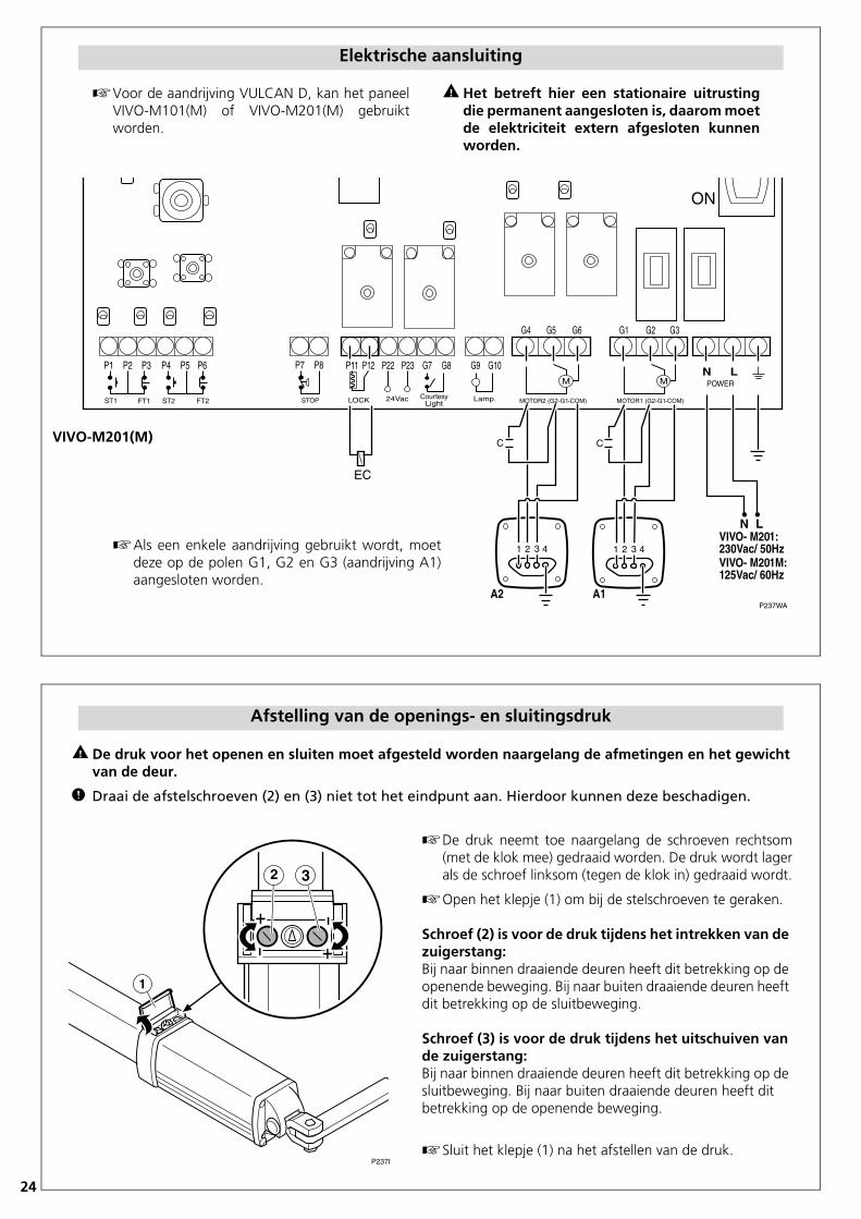
Elektrische aansluiting
VIVO-M201(M)
Voor de aandrijving VULCAN D, kan het paneelVIVO-M101(M) of VIVO-M201(M) gebruiktworden.
Het betreft hier een stationaire uitrustingdie permanent aangesloten is, daarom moetde elektriciteit extern afgesloten kunnenworden.
Als een enkele aandrijving gebruikt wordt, moetdeze op de polen G1, G2 en G3 (aandrijving A1)aangesloten worden.
�����
Afstelling van de openings- en sluitingsdruk
De druk voor het openen en sluiten moet afgesteld worden naargelang de afmetingen en het gewichtvan de deur.
O Draai de afstelschroeven (2) en (3) niet tot het eindpunt aan. Hierdoor kunnen deze beschadigen.
De druk neemt toe naargelang de schroeven rechtsom(met de klok mee) gedraaid worden. De druk wordt lagerals de schroef linksom (tegen de klok in) gedraaid wordt.
Open het klepje (1) om bij de stelschroeven te geraken.
Schroef (2) is voor de druk tijdens het intrekken van de zuigerstang:Bij naar binnen draaiende deuren heeft dit betrekking op de openende beweging. Bij naar buiten draaiende deuren heeft dit betrekking op de sluitbeweging.
Schroef (3) is voor de druk tijdens het uitschuiven van de zuigerstang:Bij naar binnen draaiende deuren heeft dit betrekking op de sluitbeweging. Bij naar buiten draaiende deuren heeft dit betrekking op de openende beweging.
Sluit het klepje (1) na het afstellen van de druk.

25
VULCAN DSkrócony przewodnik instalacji i programowania Polski
OSTRZEŻENIE
Niniejszy przewodnik zawiera wybrane informacje z pełnej wersji instrukcji instalacji. W instrukcji tejpodano zalecenia bezpieczeństwa i inne ważne wskazówki, które należy wziąć pod uwagę.Instrukcję instalacji można pobrać z witryny internetowej firmy Erreka: http://www.erreka.com/Automatismos/descargaDocumentos.aspx
�����
��
��
��
��
��
��
�
Elementy instalacji automatycznej do bram
Instalacja elektrycznaA: Zasilanie główneB: Lampa ostrzegawcza LUMIC: Fotokomórki (Rx/Tx)D: Włącznik ścienny / przełącznik kluczaE: AntenaF: Zintegrowana antena LUMIG: Zamek elektryczny
WAŻNA UWAGA!We wszystkich przypadkach należykoniecznie zainstalować ogranicznikzamykania TC i ograniczniki otwierania TA.
ZZamek elektryczny jest obowiązkowy w przypadkusiłowników bez blokady. W przypadku siłowników zblokadą zamek elektryczny wymagany jest tylko przyskrzydłach dłuższych niż 1,8 m.
MSH
-024
/01

26
�����
�
Odblokowanie
Odblokowanie obsługi ręcznej:• Zdejmij pokrywę (1).• Obróć kluczyk (2) o 90°, aby
ustawić go prostopadle dotłoczyska siłownika.
Zablokowanie obsługi ręcznej wcelu przejścia na automatyczną:• Obróć kluczyk (2) o 90°, aby
ustawić go równolegle dotłoczyska siłownika.
• Zamknij pokrywę (1).
Zablokowany Odblokowany
�����
�
�
�
�
�����
�����
Wymiary montażowe
Otwieranie do wewnątrz
Otwieranie na zewnątrz
�����
Wymiar B
Wymiar A
Kąt otwierania
130
155
80º
130
140
85º
120
140
90º
145
115
90º
125
125
95º
120
120
100º
120
105
110º
Wymiar B
Wymiar A
Kąt otwierania
135
150
80º
125
150
85º
155
100
90º
130
130
90º
130
120
95º
135
100
100º
125
95
110º

27
�����
Poziomowanie
Siłownik należy zamontowaćpoziomo: w tym celu wspornikipowinny znajdować się na tym samympoziomie.
Sprawdź ustawienie za pomocąpoziomicy.
����������
�����
�����
�����
����� �����
Montaż
7 Zamocuj przepust kablowy i wsuńkable.Potrzebne będą cztery przewody.
8 Połącz kable zgodnie z opisempodanym w następnym rozdziale.Następnie przymocuj osłonę (T) izaciśnij przepust kablowy.
9 Wyreguluj siłę zamykania iotwierania zgodnie z instrukcjamipodanymi na następnej stronie.Podnieś pokrywę (1), wyregulujśruby (1) i (2), a następnie zamknijpokrywę (1).
1 Zamocuj widełki przy siłowniku.Jako oś wykorzystaj dostarczonysworzeń poziomy.
2 Zamocuj wsporniki. Na czasspawania siłownik należy zdjąć iodłożyć w bezpieczne miejsce,ponieważ rozpryski spawalniczemogą go łatwo uszkodzić.
3 Zamocuj siłownik w tylnymwsporniku. Jako oś wykorzystaj dostarczonysworzeń z wąskim łbem.
����������
4 Zamontuj siłownik na przednimwsporniku, wykorzystującdostarczoną śrubę jako oś.
ZNajpierw dokładnie nasmarujtłoczysko i otwory.
5 Zamontuj obudowę i pokrywę.Przykręć elementy odpowiednimiśrubami.
6 Poluzuj śrubę zaworuodpowietrzającego (P). Przedewentualnym demontażemsiłownika dokręć śrubę, abynie dopuścić do wycieku oleju.
28
��� ���
�� �� ��
��� ���
�� �� �
����
�� �� ��� ���
�������� ����
��� ��� �� ��� ���
���� !"#�$%&
�'()
*� *� *� *�
���'+
*� *� * *� *� *�
���� ��� ���� ���
� ���,�-
����-�./*�0*�0���1 ����-�./*�0*�0���1
����,�
� �������� ������������������� �� ����������
�� �
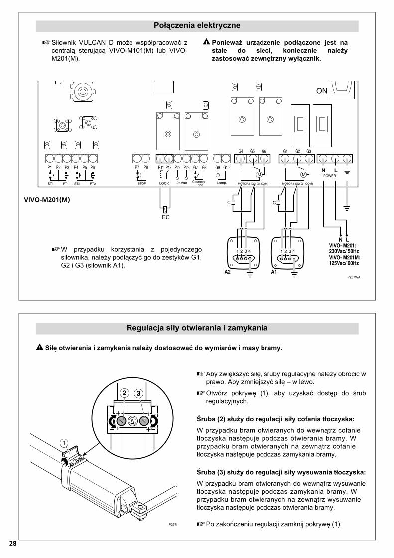
Połączenia elektryczne
VIVO-M201(M)
ZSiłownik VULCAN D może współpracować zcentralą sterującą VIVO-M101(M) lub VIVO-M201(M).
‹ Ponieważ urządzenie podłączone jest nastałe do sieci, koniecznie należyzastosować zewnętrzny wyłącznik.
ZW przypadku korzystania z pojedynczegosiłownika, należy podłączyć go do zestyków G1,G2 i G3 (siłownik A1).
�����
Regulacja siły otwierania i zamykania
‹ Siłę otwierania i zamykania należy dostosować do wymiarów i masy bramy.
ZAby zwiększyć siłę, śruby regulacyjne należy obrócić wprawo. Aby zmniejszyć siłę – w lewo.
ZOtwórz pokrywę (1), aby uzyskać dostęp do śrubregulacyjnych.
Śruba (2) służy do regulacji siły cofania tłoczyska:W przypadku bram otwieranych do wewnątrz cofanietłoczyska następuje podczas otwierania bramy. Wprzypadku bram otwieranych na zewnątrz cofanietłoczyska następuje podczas zamykania bramy.
Śruba (3) służy do regulacji siły wysuwania tłoczyska:W przypadku bram otwieranych do wewnątrz wysuwanietłoczyska następuje podczas zamykania bramy. Wprzypadku bram otwieranych na zewnątrz wysuwanietłoczyska następuje podczas otwierania bramy.
ZPo zakończeniu regulacji zamknij pokrywę (1).