Embed Size (px)
Citation preview
Regulation No. 112
Uniform provisions concerning the approval of motor vehicle headlamps
emitting an asymmetrical passing-beam or a driving-beam or both and
equipped with filament lamps and/or light-emitting diode (LED) modules
協定規則第 112 号
フィラメント電球及び/又は発光ダイオード(LED)モジュールを装備し、非
対称すれ違い用ビーム又は主走行ビーム又はその両方を発する自動車前照灯
の認可に関する統一規定
Contents 目次
A. Administrative provisions
Scope
1. Definitions
2. Application for approval of a headlamp
3. Markings
4. Approval
B. Technical requirements for headlamps
5. General specifications
6. Illumination
7. Colour
8. Gauging of discomfort
C. Further administrative provisions
9. Modification of the headlamp type and extension of approval
10. Conformity of production
11. Penalties for non-conformity of production
12. Production definitively discontinued
13. Names and addresses of Technical Services responsible for conducting approval
tests and of Type Approval Authorities
14. Transitional provisions
A. 行政規定
適用範囲
1. 定義
2. 前照灯の認可申請
3. 表示等
4. 認可
B. 前照灯の技術要件
5. 一般仕様
6. 照明
7. 色
8. 不快度の測定
C. 追加行政規定
9. 前照灯型式の変更及び認可の拡大
10. 生産の適合性
11. 生産の不適合に対する罰則
12. 生産中止
13. 認可試験を担当する技術試験機関及び行政官庁の名称及び所在地
14. 過渡規定
Annexes
1 Communication
附則
附則 1 通知
2 Examples of arrangement of approval marks
3 Spherical coordinate measuring system and test point locations
4 Tests for stability of photometric performance of headlamps in operation
Appendix 1 - Overview of operational periods concerning test for stability of
photometric performance
5 Minimum requirements for conformity of production control procedures
6 Requirements for lamps incorporating lenses of plastic material - Testing of lens or
material samples and of complete lamps
Appendix 1 - Chronological order of approval tests
Appendix 2 - Method of measurement of the diffusion and transmission of light
Appendix 3 - Spray testing method
Appendix 4 - Adhesive tape adherence test
7 Minimum requirements for sampling by an inspector
8 Overview of operational periods concerning tests for stability of photometric
performance
9 Instrumental verification of the "cut-off" for passing-beam headlamps
10 Requirements for LED modules and headlamps including LED modules
11 A general illustration for principal passing-beam and beam contributors and
correlated light source options
附則 2 認可マークの配置例
附則 3 球座標測定系及び測定点の位置
附則 4 点灯中の前照灯の配光性能の安定性に関する試験
付録 1-配光性能安定性試験に関する点灯時間の概要
附則 5 生産の適合性の管理手順に関する最小要件
附則 6 プラスチック材料のレンズを組み込んだ灯火装置の要件-レンズ又は
供試材料及び完成灯火装置の試験
付録 1-認可試験の実施手順
付録 2-光の拡散及び透過の測定方法
付録 3-噴霧試験方法
付録 4-粘着テープによる粘着試験
附則 7 検査官による抜取検査の最小要件
附則 8 配光性能の安定性試験に関する点灯時間の概要
附則 9 すれ違い用ビーム前照灯の「カットオフ」に関する計測による検証
附則 10 LED モジュール及び LED モジュール内蔵前照灯に関する要件
附則 11 主要なすれ違い用ビーム及びビーム成分並びに相関する光源オプシ
ョンに関する概略図
A. Administrative provisions
Scope1 1 Nothing in this Regulation shall prevent a Party to the Agreement applying this
Regulation from prohibiting the combination of a headlamp incorporating a lens of
plastic material
approved under this Regulation with a mechanical headlamp-cleaning device (with
wipers).
A. 行政規定
適用範囲 1
1本規則のいかなる規定も、本規則を適用する協定締約国が、本規則に基づい
て認可されるプラスチック材料のレンズを組み込んだ前照灯に機械式前照灯
洗浄装置(ワイパー付き)を組み合わせることを禁止することを妨げないもの
とする。

This Regulation applies to headlamps for vehicles of categories L, M, N and T2.
2 As defined in the Consolidated Resolution on the Construction of Vehicles
(R.E.3.), document ECE/TRANS/WP.29/78/Rev.2, para. 2.
本規則は、L 区分、M 区分、N 区分及び T2区分の自動車の前照灯に適用する。
2車両構造統合決議(R.E.3)、文書 ECE/TRANS/WP.29/78/Rev.2、2 項の定義に
基づく。
1. Definitions
For the purpose of this Regulation,
1. 定義
本規則の意図するところでは、
1.1. "Lens" means the outermost component of the headlamp (unit) which transmits
light through the illuminating surface;
1.1. 「レンズ」とは、照射面から光を透過する前照灯(ユニット)の最も外側
の構成部品を指す。
1.2. "Coating" means any product or products applied in one or more layers to the
outer face of a lens;
1.2. 「コーティング」とは、レンズの外側表面に一層以上塗る製品(単一又は
複数の製品)を指す。
1.3. "Headlamps of different types" means headlamps which differ in such essential
respects as:
1.3. 「型式の異なる前照灯」とは、下記のような本質的な観点で相違がある前
照灯を指す。
1.3.1. The trade name or mark; 1.3.1. 商号または商標
1.3.2. The characteristics of the optical system; 1.3.2. 光学機構の特性
1.3.3. The inclusion or elimination of components capable of altering the optical
effects by reflection, refraction, absorption and/or deformation during operation;
1.3.3 作動中に反射、屈折、吸収及び/又は変形により光学的効果を変えること
ができる構成部品の追加又は削除。
1.3.4. Suitability for right-hand or left-hand traffic or for both traffic systems; 1.3.4. 右側通行、左側通行又は左右両側通行区分への適性。
1.3.5. The kind of beam produced (passing beam, driving beam or both); 1.3.5. 発生するビームの種類(すれ違い用ビーム、主走行ビーム又は両方)。
1.3.6. The category of filament lamp used and/ or the LED module specific
identification code(s);
1.3.6. 使用するフィラメント電球の区分及び/又は LEDモジュールの特定識別
コード。
1.3.7. However, a device intended for the installation on the left side of the vehicle
and the corresponding device intended for the installation on the right side of the
vehicle shall be considered to be of the same type.
1.3.7. ただし、車両の左側に取り付ける装置、及びそれに対応する車両の右側
に取り付ける装置は、同一型式のものとみなされる。
1.3.8. However, a device intended for the installation on the left side of the vehicle
and the corresponding device intended for the installation on the right side of the
1.3.8. ただし、車両の左側に取り付ける装置、及びそれに対応する車両の右側
に取り付ける装置は、同一型式のものとみなされる。

vehicle shall be considered to be of the same type.
1.4. Headlamps of different "Classes" (A or B) mean headlamps identified by
particular photometric provisions.
1.4. 「等級」(A 又は B)の異なる前照灯とは、特定の配光規定によって識別
される前照灯を指す。
1.5. The definitions given in Regulation No. 48 and its series of amendments in
force at the time of application for type approval shall apply to this Regulation.
1.5. 協定規則第 48 号及び型式認可申請時点で有効な同規則の改訂版に記載さ
れている定義が適用されるものとする。
1.6. References made in this Regulation to standard (etalon) filament lamp(s) and to
Regulation No. 37 shall refer to Regulation No. 37 and its series of amendments in
force at the time of application for type approval.
1.6. 本規則内の標準(エタロン)フィラメント電球及び協定規則第 37 号に対
する参照指示は、協定規則第 37 号及び型式認可申請時点で有効な同規則の改
訂版を指すものとする。
2. Application for approval of a headlamp 2. 前照灯の認可申請
2.1. The application for approval shall be submitted by the owner of the trade name
or mark or by his duly accredited representative. It shall specify:
2.1. 認可申請書は、商号若しくは商標の所有者又は正規の委任代理人が提出す
るものとする。この申請書には、以下を記載しなければならない。
2.1.1. Whether the headlamp is intended to provide both a passing-beam and a
driving-beam or only one of these beams;
2.1.1. 前照灯がすれ違い用ビームと主走行ビームの両方を照射することを目
的としたものか、そのいずれかのみを照射することを目的としたものかの区
別。
2.1.2. Whether, if the headlamp is intended to provide a passing-beam, it is designed
for both left-hand and right-hand traffic or for either left-hand or right-hand traffic
only;
2.1.2. 前照灯がすれ違い用ビームを照射することを目的としたものである場
合には、当該ランプが左側通行と右側通行の両方を対象としているか、又は左
側通行若しくは右側通行のいずれかを対象としているかの区別。
2.1.3. If the headlamp is equipped with an adjustable reflector, the mounting
position(s) of the headlamp in relation to the ground and the longitudinal median
plane of the vehicle;
2.1.3. 前照灯に調節式反射器を装備している場合には、地面及び車両の中央縦
断面に対する前照灯の取り付け位置。
2.1.4. Whether it concerns a Class A or B headlamp; 2.1.4. 等級 A 前照灯又は等級 B 前照灯のいずれに関するものかの区別。
2.1.5. The category of the filament lamp(s) used, as listed in Regulation No. 37 and
its series of amendments in force at the time of application for type approval, and/or
the light source module specific identification code(s) for LED modules, if available.
2.1.5. 協定規則第 37 号及び型式認可申請時点で有効な同規則の改訂版に記載
されている使用フィラメント電球の区分、及び/又は LED モジュールの光源モ
ジュール特定識別コード(ある場合)。
2.2. Every application for approval shall be accompanied by: 2.2. 各認可申請書には、以下を添付しなければならない。
2.2.1. Drawings in triplicate in sufficient detail to permit identification of the type 2.2.1. 前照灯の型式が識別できる程度に詳細な、前照灯の正面像を表した外観

and representing a frontal view of the headlamp, with details of lens ribbing if any,
and the cross section. The drawings shall indicate the space(s) reserved for the
approval mark and in case of LED module(s) also the space reserved for the specific
identification code(s) of the module(s);
図 3 通。レンズにリブが付いている場合はその詳細及び断面を記載すること。
当該外観図には、認可マークのためのスペースを示すものとし、LED モジュ
ールの場合にはモジュールの特定識別コードのためのスペースも示すものと
する。
2.2.1.1. If the headlamp is equipped with an adjustable reflector, an indication of the
mounting position(s) of the headlamp in relation to the ground and the longitudinal
median plane of the vehicle, if the headlamp is for use in that (those) position(s)
only;
2.2.1.1. 前照灯に調節式反射器を装備している場合には、地面及び車両の中央
縦断面に対する前照灯の取り付け位置の表示。ただし、前照灯が当該位置で使
用されるものである場合に限る。
2.2.2. A brief technical description including, in the case where headlamps are used
to produce bend lighting, the extreme positions according to paragraph 6.2.7.below.
In the case of LED module(s) this shall include:
(a) A brief technical specification of the LED module(s);
(b) A drawing with dimensions and the basic electrical and photometric values and
the objective luminous flux and for each LED module a statement whether it is
replaceable or not;
(c) In case of electronic light source control gear, information on the electrical
interface necessary for approval testing;
2.2.2. 簡潔な技術的説明。前照灯が屈曲照明を発生させるために使用される場
合は下記 6.2.7 項に基づく極限位置を含む。LED モジュールの場合には、以下
を含むものとする。
(a) LED モジュールの簡潔な技術仕様。
(b) 寸法を記した図面、基本的な電気値及び配光測定値並びに目標光束値、及
び各 LED モジュールについては、交換式であるかどうかの記述。
(c) 電子式光源制御装置の場合は、認可試験に必要な電気的インターフェース
に関する情報。
2.2.3. Two samples of each type of headlamp, one sample intended for the
installation on the left side of the vehicle and one sample intended for the
installation of the right side of the vehicle.
2.2.3. 各型式の前照灯の供試品 2 個。車両の左側に取り付ける供試品 1 個及び
車両の右側に取り付ける供試品 1 個。
2.2.4. For the test of plastic material of which the lenses are made:
2.2.4.1. Fourteen lenses;
2.2.4. レンズを構成するプラスチック材料の試験用として
2.2.4.1. レンズ 14 枚
2.2.4.1.1. Ten of these lenses may be replaced by ten samples of material at least 60
x 80 mm in size, having a flat or convex outer surface and a substantially flat area
(radius of curvature not less than 300 mm) in the middle measuring at least 15 x 15
mm;
2.2.4.1.1. これらのレンズのうち 10 枚は、大きさが少なくとも 60×80mm の供
試材料 10 枚に代えることができる。供試材料は、外面が平坦又は凸型で、中
央に少なくとも 15×15mm の大きさのほぼ平坦な領域(曲率半径が 300mm 以
上)があること。
2.2.4.1.2. Every such lens or sample of material shall be produced by the method to 2.2.4.1.2. これらのレンズ又は供試材料は、量産時に使用される方法によって
be used in mass production; 生産されたものとする。
2.2.4.2. A reflector to which the lenses can be fitted in accordance with the
manufacturer's instructions.
2.2.4.2. メーカーの指示に従ってレンズを取り付けることができる反射器 1
個。
2.2.5. For testing the ultraviolet (UV)-resistance of light transmitting components
made of plastic material against UV radiation of LED modules inside the headlamp:
2.2.5. 前照灯内部の LED モジュールの紫外線(UV)照射に対する、プラスチ
ック材料からなる透光部品の耐紫外線性に関する試験用として、
2.2.5.1. One sample of each of the relevant material as being used in the headlamp
or one headlamp sample containing these. Each material sample shall have the same
appearance and surface treatment, if any, as intended for use in the headlamp to be
approved;
2.2.5.1. 前照灯で使用する各該当する供試材料 1 個又はこれらを含む前照灯供
試品 1 個。各供試材料は、認可の対象となる前照灯で使用されるものと同一の
外観及び表面処理(該当する場合)を有するものとする。
2.2.5.2. The UV-resistance testing of internal materials to light source radiation is
not necessary if no LED modules other than low-UV-types as specified in Annex 10
of this Regulation are being applied or if provisions are taken, to shield the relevant
headlamp components from UV radiation, e.g. by glass filters.
2.2.5.2. 本規則、附則 10 の規定に基づく低紫外線タイプ以外の LED モジュー
ルを一切使用しない場合、又は、ガラスフィルターなどで、該当する前照灯構
成部品を紫外線照射から保護するための手段が講じられている場合には、光源
の照射に対する内部材料の耐紫外線性試験は不要とする。
2.2.6. One electronic light source control gear, if applicable. 2.2.6. 電子式光源制御装置 1 個(該当する場合)。
2.3. The materials making up the lenses and coatings, if any, shall be accompanied
by the test report of the characteristics of these materials and coatings if they have
already been tested.
2.3. レンズ及びコーティングを構成する材料(ある場合)に対して既に試験が
行われている場合には、これらの材料の特性に関する試験成績書を添付するも
のとする。
3. Markings 3. 表示等
3.1. Headlamps submitted for approval shall bear the trade name or mark of the
applicant.
3.1. 認可のために提出する前照灯には、申請者の商号又は商標を表示しなけれ
ばならない。
3.2. They shall comprise, on the lens and on the main body3, spaces of sufficient size
for the approval mark and the additional symbols referred to in paragraph 4; these
spaces shall be indicated on the drawings referred to in paragraph 2.2.1. above. 3 If the lens cannot be detached from the main body of the headlamp, a unique
marking as per paragraph 4.2.5. shall be sufficient.
3.2. 前照灯には、レンズ及び本体上に 3、認可マーク及び 4 項に記した追加記
号のための十分な大きさのスペースを設けなければならない。このスペース
は、上記 2.2.1 項に記す外観図に示すものとする。
3レンズが前照灯の本体から外せない場合、4.2.5 項に基づく独特の表示で十分
とする。
3.3. Headlamps equipped with passing-beam designed to satisfy the requirements 3.3. 右側通行と左側通行の両方の要件を満たすよう設計されたすれ違い用ビ

both of right-hand and of left-hand traffic shall bear markings indicating the two
settings of the optical unit or LED module on the vehicle or of the filament lamp on
the reflector; these markings shall consist of the letters "R/D" for the position for
right-hand traffic and the letters "L/G" for the position for left-hand traffic.
ームを装備した前照灯には、車両上の光学装置若しくは LED モジュール又は
反射器上のフィラメント電球の 2つの設定を示す表示をしなければならない。
この表示は、右側通行の位置については「R/D」という文字で表し、左側通行
の位置については「L/G」という文字で表すものとする。
3.4. In the case of lamps with LED module(s), the lamp shall bear the marking of the
rated voltage and rated wattage and the light source module specific identification
code.
3.4. LED モジュールを装備する灯火装置の場合、当該灯火装置には、定格電圧
及び定格ワット数並びに光源モジュール特定識別コードを示す表示をしなけ
ればならない。
3.5. LED module(s) submitted along with the approval of the lamp: 3.5. 灯火装置の認可とともに提出される LED モジュールには、
3.5.1. Shall bear the trade name or mark of the applicant. This marking shall be
clearly legible and indelible;
3.5.1. 申請者の商号又は商標を表示するものとする。この表示は、明確に判読
でき、かつ消えないものでなければならない。
3.5.2. Shall bear the specific identification code of the module. This marking shall
be clearly legible and indelible.
This specific identification code shall comprise the starting letters "MD" for
"MODULE" followed by the approval marking without the circle as prescribed in
paragraph 4.2.1. below and in the case several non-identical light source modules are
used, followed by additional symbols or characters. This specific identification code
shall be shown in the drawings mentioned in paragraph 2.2.1. above. The approval
marking does not have to be the same as the one on the lamp in which the module is
used, but both markings shall be from the same applicant.
3.5.2. モジュールの特定識別コードを表示するものとする。この表示は、明確
に判読でき、かつ消えないものでなければならない。
この特定識別コードは、「MODULE」を意味する「MD」の文字から始まり、
下記 4.2.1 項に規定する認可マークから円を取り除いたものが続くものとし、
いくつかの非同一光源モジュールを使用する場合には、追加の記号又は文字が
続くものとする。この特定識別コードは、上記 2.2.1 項に記した図面に示すも
のとする。認可マークは、当該モジュールが使用される灯火装置上のマーキン
グと同一である必要はないが、両マーキングは同じ申請者から出されるものと
する。
3.5.3. If the LED module(s) are non-replaceable, the markings for LED module(s)
are not required.
3.5.3. LED モジュールが非交換式である場合は、LED モジュールの表示は要求
されない。
3.6. If an electronic light source control gear which is not part of a LED module is
used to operate a LED module(s), it shall be marked with its specificidentification
code(s), the rated input voltage and wattage.
3.6. LED モジュールの一部ではない電子式光源制御装置を用いて LED モジュ
ールを作動させる場合、当該ギアには、その特定識別コード、定格入力電圧及
びワット数を表示するものとする。
4. Approval
4.1. General
4. 認可
4.1. 一般要件
4.1.1. If all the samples of a type of headlamp submitted pursuant to paragraph 2.
above satisfy the provisions of this Regulation, approval shall be granted.
4.1.1. 上記 2項に基づいて提出された前照灯の型式の供試品すべてが本規則の
規定を満たす場合には、認可を付与するものとする。
4.1.2. Where grouped, combined or reciprocally incorporated lamps satisfy the
requirements of more than one Regulation, a single international approval mark may
be affixed provided that each of the grouped, combined or reciprocally incorporated
lamps satisfies the provisions applicable to it.
4.1.2. 集合式、結合式又は兼用式ランプが複数の協定規則の要件を満たす場合
には、各集合式、結合式又は兼用式ランプが各々に適用される規定を満たす場
合に限り、単一の国際認可マークを付けることができるものとする。
4.1.3. An approval number shall be assigned to each type approved. Its first two
digits shall indicate the series of amendments incorporating the most recent major
technical amendments made to the Regulation at the time of issue of the approval.
The same Contracting Party may not assign the same number to another type of
headlamp covered by this Regulation.
4.1.3. 認可された型式にはそれぞれ認可番号を割り当てるものとする。認可番
号の上二桁は認可発行時において本規則に加えられた最新の主要技術的修正
事項を織り込んだ改訂版を示すものとする。同一締約国内においては、本規則
の対象となる異なる型式の前照灯に対し同一番号を割り当てないものとする。
4.1.4. Notice of approval or of extension or refusal or withdrawal of approval or
production definitely discontinued of a type of headlamp pursuant to this Regulation
shall be communicated to the Parties to the 1958 Agreement applying this
Regulation, by means of a form conforming to the model in Annex 1 to this
Regulation, with the indications according to paragraph 2.2.1.1.
4.1.4. 本規則に基づく前照灯の型式の認可、又は認可の拡大、拒否、若しくは
取消、又は生産中止の通知は、本規則の附則 1 のひな形に準拠する書式を用い
て、2.2.1.1 項に基づく記載と共に、本規則を適用する 1958 年協定締約国に通
知するものとする。
4.1.4.1. If the headlamp is equipped with an adjustable reflector and if this headlamp
is to be used only in mounting positions according to the indications in paragraph
2.2.1.1. the applicant shall be obliged by the Type Approval Authority to inform the
user in a proper way about the correct mounting position(s).
4.1.4.1. 前照灯に調節式反射器を装備しており、かつ、この前照灯が 2.2.1.1 項
に指示された取り付け位置のみで使用される場合、申請者は、正しい取り付け
位置を適切な方法で使用者に知らせることを行政官庁により義務付けられる
ものとする。
4.1.5. In addition to the mark prescribed in paragraph 3.1., an approval mark as
described in paragraphs 4.2. and 4.3. below shall be affixed in the spaces referred to
in paragraph 3.2. above to every headlamp conforming to a type approved under this
Regulation.
4.1.5. 本規則に基づいて認可された型式に適合する各前照灯には、3.1 項に規
定する表示に加えて、下記 4.2 項及び 4.3 項に定める認可マークを上記 3.2 項
に記したスペースに付けるものとする。
4.2. Composition of the approval mark
The approval mark shall consist of:
4.2. 認可マークの構成
認可マークは、以下の通り構成するものとする。
4.2.1. An international approval mark, comprising: 4.2.1. 以下の要素で構成される国際認可マーク
4.2.1.1. A circle surrounding the letter "E" followed by the distinguishing number of
the country which has granted approval4; 4The distinguish numbers of the Contracting Parties to the 1958 Agreement are
reproduced in Annex 3 to the Consolidated Resolution on the Construction of
Vehicles (R.E.3), document ECE/TRANS/WP.29/78/Rev.2/Amend.1.
4.2.1.1. 文字「E」の後に認可を付与した国の識別番号を記載し、全体を円で
囲む 4。 41958 年協定の締約国の識別番号は、車両構造統合決議(R.E.3)の附則 3、文
書 ECE/TRANS/WP.29/78/Rev.2/Amend.1 に再録されている。
4.2.1.2. The approval number prescribed in paragraph 4.1.3. above;
4.2.2. The following additional symbol (or symbols):
4.2.1.2. 上記 4.1.3 項に規定する認可番号
4.2.2. 以下の追加記号(1 つ又は複数)
4.2.2.1. On headlamps meeting left-hand traffic requirements only, a horizontal
arrow pointing to the right of an observer facing the headlamp, i.e. to the side of the
road on which the traffic moves;
4.2.2.1. 左側通行の要件のみを満たす前照灯には、前照灯に対して向かって右
側(すなわち道路の通行側)を指す水平矢印。
4.2.2.2. On headlamps designed to meet the requirements of both traffic systems by
means of an appropriate adjustment of the setting of the optical unit or the filament
lamp or LED module(s), a horizontal arrow with a head on each end, the heads
pointing respectively to the left and to the right;
4.2.2.2. 光学装置又はフィラメント電球又は LED モジュールの設定を適切に
調節することによって両方向の通行区分の要件も満たすよう設計された前照
灯には、両側にそれぞれ右側と左側を指す矢印が付いた 1 本の水平矢印。
4.2.2.3. On headlamps meeting the requirements of this Regulation in respect of the
passing-beam only, the letters "C" for Class A headlamp or "HC" for Class B
headlamp;
4.2.2.3. すれ違い用ビームに関してのみ本規則の要件を満たす前照灯の場合、
A 等級の前照灯には文字「C」、B 等級の前照灯には文字「HC」。
4.2.2.4. On headlamps meeting the requirements of this Regulation in respect of the
driving-beam only, the letters "R" for Class A headlamp or "HR" for Class B
headlamp;
4.2.2.4. 主走行ビームに関してのみ本規則の要件を満たす前照灯の場合、A 等
級の前照灯には文字「R」、B 等級の前照灯には文字「HR」。
4.2.2.5. On headlamps meeting the requirements of this Regulation in respect of
both the passing-beam and the driving-beam, the letters "CR" for Class A headlamp
or "HCR" for Class B headlamp;
4.2.2.5. すれ違い用ビームと主走行ビームの両方に関して本規則の要件を満た
す前照灯の場合、A 等級の前照灯には文字「CR」、B 等級の前照灯には文字
「HCR」。
4.2.2.6. On headlamps incorporating a lens of plastic material, the group of letters
"PL" to be affixed near the symbols prescribed in paragraphs 4.2.2.3. to 4.2.2.5.
above;
4.2.2.6. プラスチック材料のレンズが組み込まれた前照灯には、上記 4.2.2.3 項
から 4.2.2.5 項に規定した記号の近くに文字「PL」を付ける。

4.2.2.7. On headlamps meeting the requirements of this Regulation in respect of the
driving-beam, an indication of the maximum luminous intensity expressed by a
reference mark, as defined in paragraph 6.3.4. below, placed near the circle
surrounding the letter "E";
In the case of grouped or reciprocally incorporated driving-beam headlamps,
indication of the maximum luminous intensity of the driving-beams as a whole shall
be expressed as above.
4.2.2.7. 主走行ビームに関して本規則の要件を満たす前照灯には、下記 6.3.4
項に定義した基準点で表す最大光度の表示を、文字「E」を囲む円の近くに記
載する。
集合式又は兼用式の主走行ビーム前照灯の場合、主走行ビーム全体の最大光度
の表示を上記の通り表示するものとする。
4.2.3. In every case the relevant operating mode used during the test procedure
according to paragraph 1.1.1.1. of Annex 4 and the permitted voltage(s) according to
paragraph 1.1.1.2. of Annex 4 shall be stipulated on the approval forms and on the
communication forms transmitted to the countries which are Contracting Parties to
the Agreement and which apply this Regulation.
In the corresponding cases the device shall be marked as follows:
4.2.3. いずれの場合にも、附則 4 の 1.1.1.1 項に基づく試験手順中に用いられる
点灯モード及び附則 4 の 1.1.1.2 項に基づく許容電圧を、認可書類並びに本規
則を適用する協定国に送る通知書に記載するものとする。
該当する場合には、以下の表示を当該装置に付けるものとする。
4.2.3.1. On headlamps meeting the requirements of this Regulation which are so
designed that the filament or LED module(s) producing the principal passing-beam
shall not be lit simultaneously with that of any other lighting function with which it
may be reciprocally incorporated: an oblique stroke (/) shall be placed behind the
symbol indicating the headlamp producing the passing-beam in the approval mark.
4.2.3.1. 本規則の要件を満たす前照灯で、主要なすれ違い用ビームを発するフ
ィラメント又は LED モジュールが、兼用式の他のいずれの照明機能のビーム
とも同時に点灯しないように設計されている場合:認可マークの、すれ違い用
ビームを発する前照灯を示す記号の後に斜線(/)を付けるものとする。
4.2.3.2. On headlamps equipped with filament lamps and meeting the requirements
of Annex 4 to this Regulation only when supplied with a voltage of 6 V or 12 V, a
symbol consisting of the number 24 crossed out by an oblique cross (x), shall be
placed near the filament lamp holder.
4.2.3.2. 電圧 6V 又は 12V を供給する場合に限り、本規則の附則 4 の要件を満
たすフィラメント電球を装備した前照灯には、数字の 24 をバツ印(×)で抹
消した記号をフィラメント電球ホルダーの近くに表示するものとする。
4.2.4. The two digits of the approval number which indicate the series of
amendments incorporating the most recent major technical amendments made to the
Regulation at the time of issue of the approval and, if necessary, the required arrow
may be marked close to the above additional symbols.
4.2.4. 認可付与時点で、本規則に加えられた最新の主要技術的修正事項を織り
込んだ改訂版を示す認可番号の二桁及び、(必要な場合)要求される矢印を、
上記の追加記号の近くに表示することができる。
4.2.5. The marks and symbols referred to in paragraphs 4.2.1. to 4.2.3. above shall 4.2.5. 上記 4.2.1 項から 4.2.3 項に記された表示及び記号は、明確に判読でき、
be clearly legible and be indelible. They may be placed on an inner or outer part
(transparent or not) of the headlamp, which cannot be separated from the transparent
part of the headlamp emitting the light. In any case they shall be visible when the
headlamp is fitted on the vehicle or when a movable part such as the hood is opened.
かつ消えないものでなければならない。この表示及び記号は、前照灯の内側又
は外側で、光を発する前照灯の透明部分から分離することのできない部分(透
明であるか否かは問わない)に表示することができる。いずれの場合にも、前
照灯が車両に取り付けられているときに、又はフードなどの可動部品を開けた
ときに、これらが視認できなければならない。
4.3. Arrangement of the approval mark 4.3. 認可マークの配置
4.3.1. Independent lamps
Figures 1 to 10 of Annex 2 to this Regulation give examples of arrangements of the
approval mark with the above-mentioned additional symbols.
4.3.1. 独立灯火装置
本規則の附則 2 の図 1 から 10 に、上記の追加記号を付けた認可マークの配置
例を示す。
4.3.2. Grouped, combined or reciprocally incorporated lamps 4.3.2. 集合式、結合式、又は兼用式の灯火装置
4.3.2.1. Where grouped, combined or reciprocally incorporated lamps have been
found to comply with the requirements of several Regulations, a single international
approval mark may be affixed, consisting of a circle surrounding the letter "E"
followed by the distinguishing number of the country which has granted the
approval, and an approval number. This approval mark may be located anywhere on
the grouped, combined or reciprocally incorporated lamps, provided that:
4.3.2.1. 集合式、結合式又は兼用式の灯火装置が複数の規則の要件に適合する
ことが判明した場合、文字「E」の後に認可を付与した国の識別番号を記載し
円で囲んだものと、認可番号から成る単一の国際認可マークを表示することが
できる。この認可マークは、以下の条件に該当すれば、集合式、結合式又は兼
用式ランプのどの部位に表示してもよいものとする。
4.3.2.1.1.
It is visible as per paragraph 4.2.5.;
4.3.2.1.1.
4.2.5 項に従って視認できること。
4.3.2.1.2. No part of the grouped, combined or reciprocally incorporated lamps that
transmits light can be removed without at the same time removing the approval
mark.
4.3.2.1.2. 集合式、結合式、又は兼用式の灯火装置の光が透過するどの部位を
外す場合も、認可マークと同時でなければ外れないこと。
4.3.2.2. The identification symbol for each lamp appropriate to each Regulation
under which approval has been granted, together with the corresponding series of
amendments incorporating the most recent major technical amendments to the
Regulation at the time of issue of the approval, and if necessary, the required arrow
shall be marked:
4.3.2.2. 認可が付与される基準となった各規則に適用される各灯火装置の識別
記号、及び認可付与時点において本規則に加えられた最新の主要技術的修正事
項を織り込んだ改訂版番号、及び必要な場合には要求された矢印を以下のいず
れかの部位に表示するものとする。
4.3.2.2.1. Either on the appropriate light-emitting surface, 4.3.2.2.1. 適切な発光面上に、又は

4.3.2.2.2. Or in a group, in such a way that each of the grouped, combined or
reciprocally incorporated lamps may be clearly identified (see four possible
examples in Annex 2).
4.3.2.2.2. 集合式、結合式、又は兼用式の灯火装置のそれぞれが明確に識別で
きるような形で、1つに集合させて(附則 2 の 4 つの可能例を参照)。
4.3.2.3. The size of the components of a single approval mark shall not be less than
the minimum size required for the smallest of the individual marks by the
Regulation under which approval has been granted.
4.3.2.3. 1 つの認可マークの各構成要素のサイズは、認可が付与さ
れる基準となった規則において、最小の個別マークに要求される最小サイズを
下回らないものとする。
4.3.2.4. An approval number shall be assigned to each type approved. The same
Contracting Party may not assign the same number to another type of grouped,
combined or reciprocally incorporated lamps covered by this Regulation.
4.3.2.4. 認可番号は、認可された各型式に割り当てるものとする。同一締約国
は、本規則が適用される集合式、結合式、又は兼用式ランプの別の型式に同じ
番号を割り当ててはならない。
4.3.2.5. Figure 11 of Annex 2 to this Regulation gives examples of arrangements of
approval marks for grouped, combined or reciprocally incorporated lamps with all
the above-mentioned additional symbols.
4.3.2.5. 本規則の附則 2 の図 11 に、上記の追加記号をすべて付けた集合式、結
合式、又は兼用式ランプの認可マークの配置例を示す。
4.3.3. Lamps, the lens of which are used for different types of headlamps and which
may be reciprocally incorporated or grouped with other lamps
The provisions laid down in paragraph 4.3.2. above are applicable.
4.3.3. レンズが型式の異なる前照灯に用いられ、かつ、他の灯火装置と兼用式
か又は集合式にすることができる灯火装置
上記 4.3.2 項に定める規定を適用する。
4.3.3.1. In addition, where the same lens is used, the latter may bear the different
approval marks relating to the different types of headlamps or units of lamps,
provided that the main body of the headlamp, even if it cannot be separated from the
lens, also comprises the space described in paragraph 3.2. above and bears the
approval marks of the actual functions.
If different types of headlamps comprise the same main body, the latter may bear the
different approval marks.
4.3.3.1. さらに、同一のレンズが使用される場合には、前照灯の本体が、たと
えレンズと分離することができなくとも、上記 3.2 項に定められたスペースを
含んでおり、実際の機能に関する認可マークが表示されていれば、異なる型式
の前照灯又は灯火装置ユニットに関する異なる認可マークをレンズに付ける
ことができる。
型式の異なる複数の前照灯が同一の本体を構成している場合には、本体に異な
る認可マークを付けることができる。
4.3.3.2. Figure 12 of Annex 2 to this Regulation gives examples of arrangements of
approval marks relating to the above case.
4.3.3.2. 本規則の附則 2 の図 12 に、上記の例に関する認可マークの配置例を示
す。
B. Technical requirements for headlamps5 5 Technical requirements for filament lamps: see Regulation No. 37.
B. 前照灯の技術要件 5 5フィラメントランプの技術要件:協定規則第 37 号参照。
5. General specifications 5. 一般規定
5.1. Each sample shall conform to the specifications set forth in paragraphs 6. to 8.
below.
5.1. 各供試品は、下記 6 項から 8 項に定める規定に適合しなければならない。
5.2. Headlamps shall be so made as to retain their prescribed photometric
characteristics and to remain in good working order when in normal use, in spite of
the vibrations to which they may be subjected.
5.2. 前照灯は、通常の使用状況で予想される振動を受けても、規定された配光
特性を維持し、正常に作動できる状態を保つように製作するものとする。
5.2.1. Headlamps shall be fitted with a device enabling them to be so adjusted on the
vehicles as to comply with the rules applicable to them. Such a device need not be
fitted on units in which the reflector and the diffusing lens cannot be separated,
provided the use of such units is confined to vehicles on which the headlamp setting
can be adjusted by other means.
Where a headlamp providing a principal passing-beam and a headlamp providing a
driving-beam, each equipped with its own filament lamp or LED module(s), the
adjusting device shall enable the principal passing-beam and the driving-beam to be
adjusted individually.
5.2.1. 前照灯には、適用される規則に適合するように車両上で前照灯を調節す
ることができる装置を装備するものとする。反射器と拡散レンズを分離するこ
とができない前照灯の場合には、他の手段によって前照灯設定を調節すること
ができる車両にその使用を限定する場合に限り、上記の装置を装備する必要は
ない。
主要なすれ違い用ビームを照射する前照灯及び主走行ビームを照射する前照
灯のそれぞれに独自のフィラメント電球又は LED モジュールが装備されてい
る場合は、調節装置によって主要なすれ違い用ビームと主走行ビームを個別に
調節することができなければならない。
5.2.2. However, these provisions shall not apply to headlamp assemblies whose
reflectors are indivisible. For this type of assembly the requirements of paragraph
6.3. of this Regulation apply.
5.2.2. ただし、上記の規定は、反射器を分割することができない前照灯アッセ
ンブリには適用しないものとする。この型式のアッセンブリに対しては、本規
則の 6.3 項の要件を適用する。
5.3. The headlamp shall be equipped with: 5.3. 前照灯には以下を装備しなければならない。
5.3.1. Filament lamp(s) approved according to Regulation No. 37. Any filament
lamp covered by Regulation No. 37 may be used, provided that no restriction on the
use is made in Regulation No. 37 and its series of amendments in force at the time
of application for type approval.
5.3.1. 協定規則第 37 号に従って認可されたフィラメント電球。協定規則第 37
号の対象であれば、いずれのフィラメント電球も使用することができる。ただ
し、協定規則第 37 号及び型式認可申請時に有効なその改訂版において使用に
関する制限が記載されていないことを条件とする。
5.3.1.1. The design of the device shall be such that the filament lamp can be fixed in
no other position but the correct one6; 6 A headlamp is regarded as satisfying the requirements of this paragraph if the
5.3.1.1. 装置は、フィラメント電球を正しい位置以外には固定することができ
ないような設計でなければならない 6。
6 フィラメント電球を容易に前照灯内に装着でき、位置決め用ラグを暗やみの
filament lamp can be easily fitted into the headlamp and the positioning lugs can be
correctly fitted into their slots even in darkness.
中であっても各々のスロットに正確に入れることができれば、前照灯は本項の
要件を満たしたものとみなす。
5.3.1.2. The filament lamp holder shall conform to the characteristics given in IEC
Publication 60061. The holder data sheet relevant to the category of filament lamp
used, applies.
5.3.1.2. フィラメント電球ホルダーは、IEC 規格 60061 に収録されている特性
に適合しなければならない。使用されるフィラメント電球の区分に関連するホ
ルダーのデータシートを適用する。
5.3.1.3. A means of controlling the voltage at the terminals of the device, within the
limits as defined in Regulation No. 48, may, for convenience, be located within the
body of the headlamp. However, for the purposes of type approval of the passing
and/ or driving beam according to the provisions of this Regulation, such means of
voltage control shall not be considered to be part of the headlamp and shall be
disconnected during the testing to verify performance according to the requirements
of this Regulation.
5.3.1.3. 協定規則第 48 号に定義された制約内で、便宜上、装置の端子で電圧を
制御する手段を前照灯本体内に配置することができる。ただし、本規則の規定
に従って、すれ違い用及び/又は主走行ビームの型式認可を行う目的において、
当該電圧制御手段は、前照灯の一部とみなさないものとし、本規則の要件に従
って性能確認のために行われる試験の間は、取り外すものとする。
5.3.2. And/or LED module(s): 5.3.2. 及び/又は LED モジュール
5.3.2.1. Electronic light source control gear(s) associated with the operation of LED
module(s), if applicable, shall be considered to be part of the headlamp; they may be
part of the LED module(s);
5.3.2.1. LED モジュールの動作に関わる電子式光源制御装置(該当する場合)
は、前照灯の一部であるとみなすものとする。LED モジュールの一部である
場合もある。
5.3.2.2. The headlamp, if equipped with LED modules, and the LED module(s)
themselves shall comply with the relevant requirements specified in Annex 10 to this
Regulation. The compliance with the requirements shall be tested.
5.3.2.2. 前照灯に LED モジュールを装備する場合、当該前照灯並びに LED モ
ジュール自体が本規則の附則 10 に規定した関連要件に適合しなければならな
い。当該要件への適合に関する試験を実施するものとする。
5.3.2.3. The total objective luminous flux of all LED modules producing the
principal passing-beam and measured as described in paragraph 5. of Annex 10 shall
be equal or greater than 1,000 lumens.
5.3.2.3. 主要なすれ違い用ビームを照射するすべての LED モジュールの総目
標光束値は、附則 10 の 5 項の記載に基づいて測定したとき、1,000 ルーメン以
上でなければならない。
5.3.2.4. In the case of a replaceable LED module the removal and replacement of
this LED module, as described in Annex 10, paragraph 1.4.1. shall be demonstrated
to the satisfaction of the Technical Service.
5.3.2.4. 交換式 LED モジュールの場合、附則 10 の 1.4.1 項に記載された通り、
本 LED モジュールの取り外し及び交換を、技術機関が納得するように証明す
るものとする。
5.4. Headlamps designed to satisfy the requirements both of right hand and of left
hand traffic may be adapted for traffic on a given side of the road either by
5.4. 右側通行と左側通行の両方の要件を満たすよう設計された前照灯は、車両
取り付け時の適切な初期設定又は使用者による選択的な設定のいずれかによ
anappropriate initial setting when fitted on the vehicle or by selective setting by the
user. Such initial or selective setting may consist, for example, of fixing either the
optical unit at a given angle on the vehicle or the filament lamp or LED module(s)
producing the principal passing-beam at a given angle/position in relation to the
optical unit. In all cases, only two different and clearly distinct settings, one for right
hand and one for left-hand traffic, shall be possible, and the design shall preclude
inadvertent shifting from one setting to the other or setting in an intermediate
position. Where two different setting positions are provided for the filament lamp or
LED module(s) producing the principal passing-beam, the components for attaching
the filament lamp or LED module(s) producing the principal passing-beam to the
reflector must be so designed and made that, in each of its two settings, this filament
lamp or LED module(s) will be held in position with the precision required for
headlamps designed for traffic on only one side of the road. Conformity with the
requirements of this paragraph shall be verified by visual inspection and, where
necessary, by a test fitting.
って、道路の所定の側の交通に適合させることができるものとする。かかる初
期設定又は選択的設定は、例えば、光学装置を所定の角度で車両上に固定する
か、主要なすれ違い用ビームを照射するフィラメント電球又は LED モジュー
ルを光学装置に対して所定の角度/位置に固定することで行うことができる
ものとする。いずれの場合にも、明確に識別できる 2 つの異なる設定(右側通
行用に 1 つ、左側通行用に 1 つ)のみを可能とし、設計上、不意に一方の設定
が他方に移動したり、中間位置に設定されたりすることがないようにしなけれ
ばならない。主要なすれ違い用ビームを照射するフィラメント電球又は LED
モジュールに 2 つの異なる設定位置が用意される場合、主要なすれ違い用ビー
ムを照射するフィラメント電球又は LED モジュールを反射器に装着するため
の構成部品は、2 つの設定の各々において、道路の片側通行用のみに設計され
た前照灯に要求される精度で、当該フィラメント電球又は LED モジュールが
所定の位置に保持されるように設計、製作しなければならない。本項の要件へ
の適合は、目視検査並びに必要に応じて取付試験によって確認するものとす
る。
5.5. Complementary tests shall be done according to the requirements of Annex 4 to
ensure that in use there is no excessive change in photometric performance.
5.5. 附則 4 の要件に従って補足試験を実施することにより、使用中に配光性能
に著しい変化がないことを確認するものとする。
5.6. Light transmitting components made of plastic material shall be tested
according to the requirements of Annex 6.
5.6. プラスチック材料からなる透光部品は、附則 6 の要件に従って試験を実施
するものとする。
5.7. On headlamps designed to provide alternately a driving-beam and a
passing-beam, or a passing-beam and/or a driving-beam designed to become bend
lighting, any mechanical, electromechanical or other device incorporated in the
headlamp for these purposes shall be so constructed that:
5.7. 主走行ビーム及びすれ違い用ビーム、又は屈曲照明となるように設計され
たすれ違い用ビーム及び/又は主走行ビームとを交互に発するように設計され
た前照灯では、かかる目的のために前照灯に組み込まれた機械的、電気機械的
又はその他の形式の装置は以下のように製造しなければならない。
5.7.1. The device is robust enough to withstand 50,000 operations under normal
conditions of use. In order to verify compliance with this requirement, the Technical
Service responsible for approval tests may:
(a) Require the applicant to supply the equipment necessary to perform the test;
5.7.1. 装置は、通常の使用条件において 50,000 回の動作に耐えるに十分な強度
があること。本要件への適合を確認するために、認可試験を担当する技術機関
は以下を行うことができるものとする。
(a) 試験の実施に必要な機器を提供するよう申請者に要求すること。
(b) Forego the test if the headlamp presented by the applicant is accompanied by a
test report, issued by a Technical Service responsible for approval tests for
headlamps of the same construction (assembly), confirming compliance with this
requirement.
(b) 申請者が提出した前照灯に、認可試験を担当する技術機関から発行され
た、同一構造(アッセンブリ)の前照灯に関する試験成績書が添付されており、
それにより本要件への適合を確認できる場合に、試験なしで済ませること。
5.7.2. In the case of failure, the luminous intensity above the line H-H shall not
exceed the values of a passing-beam according to paragraph 6.2.4.; in addition, on
headlamps designed to provide a passing and/or a driving-beam to become a bend
lighting, a minimum luminous intensity of at least 2,500 cd. shall be fulfilled in test
point 25 V (VV line, 1.72D).
When performing the tests to verify compliance with these requirements, the
Technical Service responsible for approval tests shall refer to the instructions
supplied by the applicant.
5.7.2. 故障の場合は、H-H 線より上の前照灯の光度は、6.2.4 項に準拠したすれ
違い用ビームの値を超えないものとする。さらに、すれ違い用ビーム及び/又
は走行ビームを提供して屈曲照明になるよう設計された前照灯では、測定点
25V において少なくとも 2,500cd の最小光度を満たすものとする(VV 線、
1.72D)。本要件への適合を確認するために試験を実施する際、認可試験を担当
する技術機関は、申請者から提供された指示書を参照するものとする。
5.7.3. Either the principal passing-beam or the driving-beam shall always be
obtained without any possibility of the mechanism stopping in between two
positions;
5.7.3. 2 つの位置の間で機構が停止する恐れが全くなく、常に主要なすれ違い
用ビーム又は走行ビームのいずれかを得ることができるものとする。
5.7.4. The user cannot, with ordinary tools, change the shape or position of the
moving parts.
5.7.4. 使用者が通常の工具を用いて可動部品の形状や位置を変更することが
できないこと。
5.8. Illumination configuration for different traffic conditions 5.8. 異なる車両通行条件に対する照明の配置
5.8.1. In the case of headlamps designed to meet the requirements of traffic moving
on one side of the road (either right or left) only, appropriate measures shall be taken
to prevent discomfort to road-users in a country where traffic moves on the side of
the road opposite to that of the country for which the headlamp was designed7. Such
measures may be: 7 Instructions on the installation of lamps fitted with the measures are given in
Regulation No. 48.
(a) Occulting a part of the outer headlamp lens area;
(b) Downward movement of the beam. Horizontal movement is allowed;
5.8.1. 道路の片側(右側あるいは左側のいずれか)通行区分のみの要件を満た
すよう設計された前照灯の場合は、前照灯の設計対象である国と逆側通行の国
の使用者に不快感を与えないよう、適切な方策をとるものとする 7。以下のよ
うな方策が考えられる。
7 これらの措置を備えた灯火装置の取り付けに関する指示が、協定規則第 48
号に記されている。
(a) 外側前照灯のレンズ部分の一部を掩蔽する。
(b) ビームを下向きに動かす。水平方向の動きも許容される。
(c) Any other measure to remove or reduce the asymmetrical part of the beam. (c) ビームの非対称部分を除去又は削減するための他の方策。
5.8.2. Following the application of this (these) measure(s) the following
requirements regarding the luminous intensity of the headlamp shall be met with the
adjustment left unchanged compared to that for the original traffic direction:
5.8.2. これらの措置を適用した後に、当初の通行方向用の照準調整を変えるこ
となく、前照灯の光度に関する以下の要件が満たされるものとする。
5.8.2.1. Passing-beam designed for right-hand traffic and adapted to left-hand traffic:
at 0.86D-1.72L at least 2,500 cd;
at 0.57U-3.43R not more than 880 cd.
5.8.2.1. 右側通行用に設計され、左側通行用に改良したすれ違い用ビームの場
合、
0.86D-1.72L において少なくとも 2,500cd
0.57U-3.43R において 880cd を超えない
5.8.2.2. Passing-beam designed for left-hand traffic and adapted to right-hand traffic:
at 0.86D-1.72R at least 2,500 cd;
at 0.57U-3.43L not more than 880 cd.
5.8.2.2. 左側通行用に設計され、右側通行用に改良したすれ違い用ビームの場
合、
0.86D-1.72R において少なくとも 2,500cd
0.57U-3.43L において 880cd を超えない
5.9. In case of a passing-beam headlamp incorporating a light source or LED
module(s) producing the principal passing-beam and having a total objective
luminous flux which exceeds 2,000 lumens, a reference shall be made in item 9. of
the communication form in Annex 1. The objective luminous flux of LED modules
shall be measured as described in paragraph 5. of Annex 10.
5.9. 主要なすれ違い用ビームを照射する光源又は LED モジュールが組み込ま
れたすれ違い用ビーム前照灯のうち、総目標光束値が 2,000 ルーメンを超える
ものについては、附則 1 の通知書の 9 項にその旨を記載しなければならない。
LED モジュールの目標光束値は、附則 10 の 5 項の記載に基づき測定するもの
とする。
5.10. The definitions in paragraphs 2.7.1.1.3. and 2.7.1.1.7. in Regulation No. 48
allow the use of LED modules, which may contain holders for other light sources.
Notwithstanding this provision a mixture of LED'(s) and other light sources for the
principal dipped beam or the contributor to the bend lighting or each driving-beam,
as specified by this Regulation is not allowed.
5.10. 協定規則第 48 号の 2.7.1.1.3 項及び 2.7.1.1.7 項の定義は、他の光源用のホ
ルダーを含む可能性のある LED モジュールの使用を容認している。本規定に
かかわらず、本規則に規定された通り、主要な下向きビーム又は屈曲照明の成
分又は各主走行ビーム用に LED と他の光源を組み合わせることは容認されな
い。
5.11. A LED module shall be:
(a) Only removable from its device with the use of tools, unless it is stated in the
communication sheet that the LED module is non-replaceable, and
(b) So designed that regardless of the use of tool(s), it is not mechanically
5.11. LED モジュールは、
(a) 工具を使用する場合に限りその装置から取り外せるものとする。ただし、
通知書に当該 LED モジュールが非交換式であることが記載されている場合は
除く。及び、
interchangeable with any replaceable approved light source. (b) 工具の使用の有無を問わず、一切の認可済み交換式光源と機械的な互換性
がないように設計されているものとする。
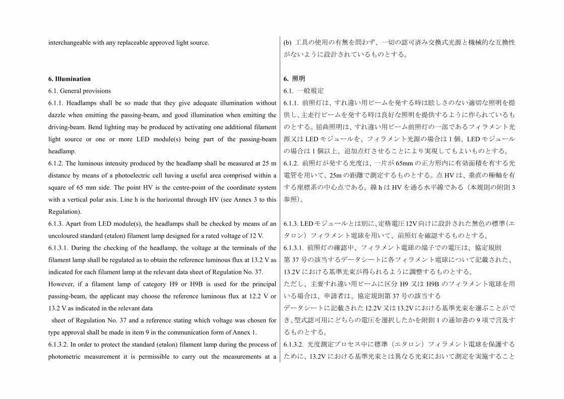
6. Illumination 6. 照明
6.1. General provisions 6.1. 一般規定
6.1.1. Headlamps shall be so made that they give adequate illumination without
dazzle when emitting the passing-beam, and good illumination when emitting the
driving-beam. Bend lighting may be produced by activating one additional filament
light source or one or more LED module(s) being part of the passing-beam
headlamp.
6.1.1. 前照灯は、すれ違い用ビームを発する時は眩しさのない適切な照明を提
供し、主走行ビームを発する時は良好な照明を提供するように作られているも
のとする。屈曲照明は、すれ違い用ビーム前照灯の一部であるフィラメント光
源又は LED モジュールを、フィラメント光源の場合は 1 個、LED モジュール
の場合は 1 個以上、追加点灯させることにより実現してもよいものとする。
6.1.2. The luminous intensity produced by the headlamp shall be measured at 25 m
distance by means of a photoelectric cell having a useful area comprised within a
square of 65 mm side. The point HV is the centre-point of the coordinate system
with a vertical polar axis. Line h is the horizontal through HV (see Annex 3 to this
Regulation).
6.1.2. 前照灯が発する光度は、一片が 65mm の正方形内に有効面積を有する光
電管を用いて、25m の距離で測定するものとする。点 HV は、垂直の極軸を有
する座標系の中心点である。線 h は HV を通る水平線である(本規則の附則 3
参照)。
6.1.3. Apart from LED module(s), the headlamps shall be checked by means of an
uncoloured standard (etalon) filament lamp designed for a rated voltage of 12 V.
6.1.3. LEDモジュールとは別に、定格電圧12V向けに設計された無色の標準(エ
タロン)フィラメント電球を用いて、前照灯を確認するものとする。
6.1.3.1. During the checking of the headlamp, the voltage at the terminals of the
filament lamp shall be regulated as to obtain the reference luminous flux at 13.2 V as
indicated for each filament lamp at the relevant data sheet of Regulation No. 37.
However, if a filament lamp of category H9 or H9B is used for the principal
passing-beam, the applicant may choose the reference luminous flux at 12.2 V or
13.2 V as indicated in the relevant data
sheet of Regulation No. 37 and a reference stating which voltage was chosen for
type approval shall be made in item 9 in the communication form of Annex 1.
6.1.3.1. 前照灯の確認中、フィラメント電球の端子での電圧は、協定規則
第 37 号の該当するデータシートに各フィラメント電球について記載された、
13.2V における基準光束が得られるように調整するものとする。
ただし、主要すれ違い用ビームに区分 H9 又は H9B のフィラメント電球を用
いる場合は、申請者は、協定規則第 37 号の該当する
データシートに記載された 12.2V又は13.2Vにおける基準光束を選ぶことがで
き、型式認可用にどちらの電圧を選択したかを附則 1 の通知書の 9 項で言及す
るものとする。
6.1.3.2. In order to protect the standard (etalon) filament lamp during the process of
photometric measurement it is permissible to carry out the measurements at a
6.1.3.2. 光度測定プロセス中に標準(エタロン)フィラメント電球を保護する
ために、13.2V における基準光束とは異なる光束において測定を実施すること
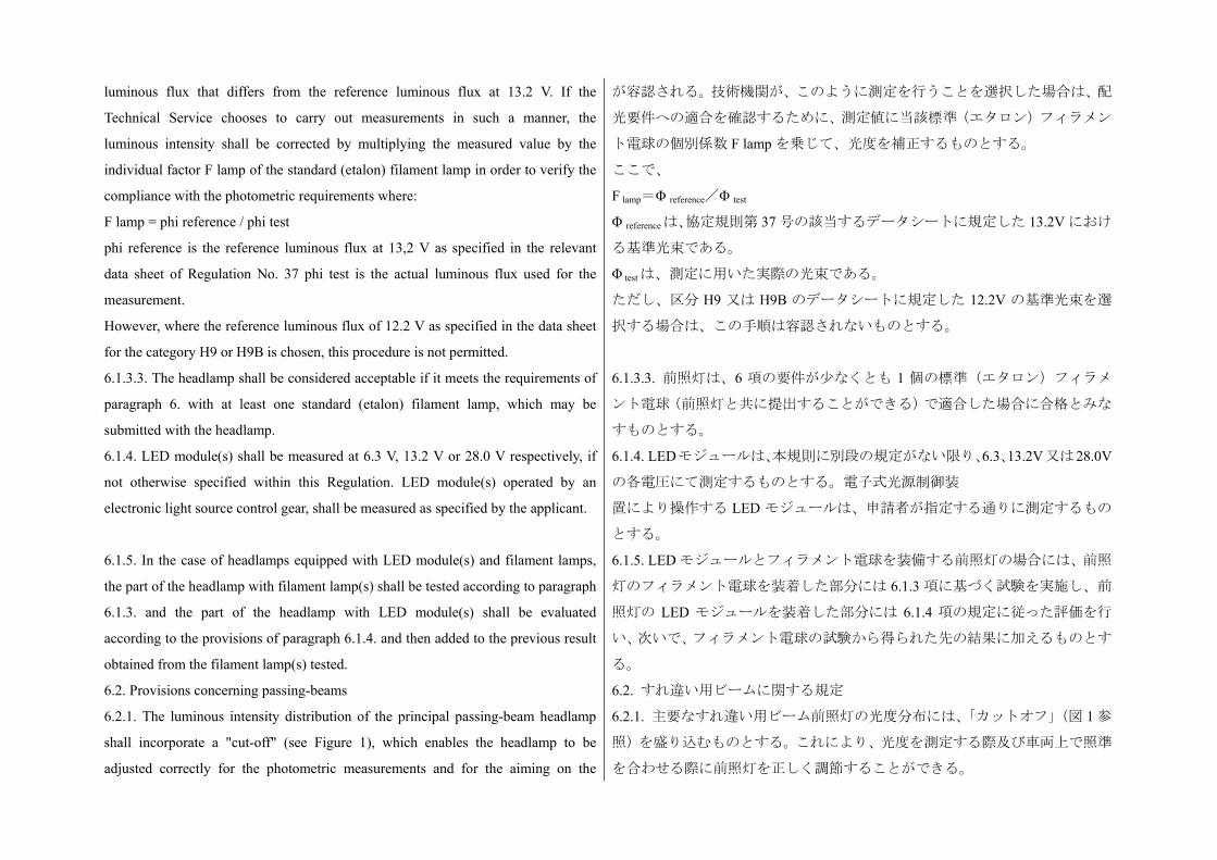
luminous flux that differs from the reference luminous flux at 13.2 V. If the
Technical Service chooses to carry out measurements in such a manner, the
luminous intensity shall be corrected by multiplying the measured value by the
individual factor F lamp of the standard (etalon) filament lamp in order to verify the
compliance with the photometric requirements where:
F lamp = phi reference / phi test
phi reference is the reference luminous flux at 13,2 V as specified in the relevant
data sheet of Regulation No. 37 phi test is the actual luminous flux used for the
measurement.
However, where the reference luminous flux of 12.2 V as specified in the data sheet
for the category H9 or H9B is chosen, this procedure is not permitted.
が容認される。技術機関が、このように測定を行うことを選択した場合は、配
光要件への適合を確認するために、測定値に当該標準(エタロン)フィラメン
ト電球の個別係数 F lamp を乗じて、光度を補正するものとする。
ここで、
F lamp=Φ reference/Φ test
Φ referenceは、協定規則第 37 号の該当するデータシートに規定した 13.2V におけ
る基準光束である。
Φ testは、測定に用いた実際の光束である。
ただし、区分 H9 又は H9B のデータシートに規定した 12.2V の基準光束を選
択する場合は、この手順は容認されないものとする。
6.1.3.3. The headlamp shall be considered acceptable if it meets the requirements of
paragraph 6. with at least one standard (etalon) filament lamp, which may be
submitted with the headlamp.
6.1.3.3. 前照灯は、6 項の要件が少なくとも 1 個の標準(エタロン)フィラメ
ント電球(前照灯と共に提出することができる)で適合した場合に合格とみな
すものとする。
6.1.4. LED module(s) shall be measured at 6.3 V, 13.2 V or 28.0 V respectively, if
not otherwise specified within this Regulation. LED module(s) operated by an
electronic light source control gear, shall be measured as specified by the applicant.
6.1.4. LEDモジュールは、本規則に別段の規定がない限り、6.3、13.2V又は28.0V
の各電圧にて測定するものとする。電子式光源制御装
置により操作する LED モジュールは、申請者が指定する通りに測定するもの
とする。
6.1.5. In the case of headlamps equipped with LED module(s) and filament lamps,
the part of the headlamp with filament lamp(s) shall be tested according to paragraph
6.1.3. and the part of the headlamp with LED module(s) shall be evaluated
according to the provisions of paragraph 6.1.4. and then added to the previous result
obtained from the filament lamp(s) tested.
6.1.5. LED モジュールとフィラメント電球を装備する前照灯の場合には、前照
灯のフィラメント電球を装着した部分には 6.1.3 項に基づく試験を実施し、前
照灯の LED モジュールを装着した部分には 6.1.4 項の規定に従った評価を行
い、次いで、フィラメント電球の試験から得られた先の結果に加えるものとす
る。
6.2. Provisions concerning passing-beams 6.2. すれ違い用ビームに関する規定
6.2.1. The luminous intensity distribution of the principal passing-beam headlamp
shall incorporate a "cut-off" (see Figure 1), which enables the headlamp to be
adjusted correctly for the photometric measurements and for the aiming on the
6.2.1. 主要なすれ違い用ビーム前照灯の光度分布には、「カットオフ」(図 1 参
照)を盛り込むものとする。これにより、光度を測定する際及び車両上で照準
を合わせる際に前照灯を正しく調節することができる。

vehicle.
The "cut-off" shall provide:
(a)For right hand traffic beams:
(i)A straight "horizontal part" towards the left;
(ii)A raised "elbow - shoulder" part towards the right.
(b)For left hand traffic beams:
(i)A straight "horizontal part" towards the right;
(ii)A raised "elbow - shoulder" part towards the left.
In each case the "elbow-shoulder" part shall have a sharp edge.
「カットオフ」は、以下を形成するものとする。
(a) 右側通行用ビームの場合
(i) 直線状の「水平部分」が左側に位置する。
(ii) 右上がりの「傾斜部分」が右側に位置する。
(b) 左側通行用ビームの場合
(i) 直線状の「水平部分」が右側に位置する。
(ii) 右上がりの「傾斜部分」が左側に位置する。
それぞれの場合において、「傾斜部分」は鋭角となるものとする。
6.2.2. The headlamp shall be visually aimed by means of the "cut-off" (see Figure 1)
as follows. The aiming shall be carried out using a flat vertical screen set up at a
distance of 10 m or 25 m (as indicated in item 9 of Annex 1) forward of the
headlamp and at right angles to the H-V axis as shown in Annex 3 to this
Regulation. The screen shall be sufficiently wide to allow examination and
adjustment of the "cut-off" of the passing-beam over at least 5 deg. on either side of
the V-V line.
6.2.2. 前照灯は、下記の通り「カットオフ」を用いて目視によって照準を合わ
せるものとする(図 1 参照)。照準調整は、前照灯の前方 10m 又は 25m で、本
規則の附則 3 に示す通り、H-V 軸に対して適切な角度に設置した平坦な垂直の
スクリーンを用いて実施するものとする(附則 1 の 9 項に示す)。当該スクリ
ーンは、V-V 線の両側でそれぞれ少なくとも 5°にわたって、すれ違い用ビー
ムの「カットオフ」の確認と調整を可能にするのに十分な幅を有するものとす
る。
6.2.2.1. For vertical adjustment: the horizontal part of the "cut-off" is moved upward
from below line B and adjusted to its nominal position one per cent (0.57 degrees)
below the H-H line;
6.2.2.1. 垂直方向の調整の場合、「カットオフ」の水平部を線 B の下方から上
方に動かし、H-H 線の下方 1%(0.57°)の公称位置に調整する。
Figure 1 図 1

Note: The scales are different for vertical and horizontal lines. 注:垂直線と水平線の尺度は異なる。
6.2.2.2. For horizontal adjustment: the "elbow - shoulder" part of the "cut-off" shall
be moved:
For right hand traffic from right to left and shall be horizontally positioned after its
movement so that:
(a) Above the line 0.2 deg. D its "shoulder" shall not exceed the line A to the left;
(b) The line 0.2 deg. D or below its "shoulder" should cross the line A; and
(c) The kink of the "elbow" is basically located within +/-0.5 degrees to the left or
right of the V-V line;
or
For left hand traffic from left to right and shall be horizontally positioned after its
movement so that:
(a) Above the line 0.2 D its "shoulder" shall not exceed the line A to the right;
(b) On the line 0.2 deg. or below its "shoulder" cross the line A; and
(c) The kink of the "elbow" should be primarily on the V-V line;
6.2.2.2. 水平調節を行うには、「カットオフ」の「傾斜部分」を、以下の通り移
動するものとする。
右側通行については、右から左に移動し、移動後は以下の条件を満たすよう、
水平となるものとする。
(a) 線 0.2°D の上方では、「傾斜部分」が左にある線 A を超えないものとする。
(b) 線 0.2°D の線上又は下方では、「傾斜部分」が線 A と交差するものとする。
(c) 基本的に、屈折点である「エルボー点」は V-V 線の左又は右に±0.5°内に位
置する。
左側通行の場合は、左から右へ。移動後、以下を達成するよう水平に配置する
ものとする。
(a) 線 0.2°D よりも上では、「傾斜部分」は線 A を超えて右側には行かないも
のとする。
(b) 線 0.2°D 上、又はそれより下では、「傾斜部分」は線 A と交差すべきもの
「屈折点」
「傾斜部分」
とする。
(c) 屈折点である「エルボー点」は、主に V-V 線上に位置すべきものとする。
6.2.2.3. Where a headlamp so aimed does not meet the requirements set out in
paragraphs 6.2.4. to 6.2.6. and 6.3., its alignment may be changed, provided that the
axisof the beam is not displaced:
Horizontally from line A by more than:
(a) 0.5 deg. to the left or 0.75 deg. to the right, for right hand traffic; or
(b) 0.5 deg. to the right or 0.75 deg. to the left, for left hand traffic; and Vertically
not more than 0.25 deg. up or down from line B.
6.2.2.3. 上記の通りに照準を合わせた前照灯が 6.2.4 項から 6.2.6 項並びに 6.3
項に規定された要件を満たさない場合には、ビームの軸に以下のずれが生じな
いことを条件に、位置合わせを変更できるものとする。
以下を超えた、水平方向の線 A からのずれ。
(a) 右側通行の場合、左に 0.5°又は右に 0.75°、あるいは、
(b) 左側通行の場合、右に 0.5°又は左に 0.75°。並びに、
0.25°以下の、垂直方向の線 B からの上方又は下方のずれ
6.2.2.4. If, however, vertical adjustment cannot be performed repeatedly to the
required position within the tolerances described in paragraph 6.2.2.3. above, the
instrumental method of Annex 9, paragraphs 2. and 3. shall be applied to test
compliance with the required minimum quality of the "cut-off" and to perform the
vertical and horizontal adjustment of the beam.
6.2.2.4. ただし、必要な位置への垂直調節を上記 6.2.2.3 項に記載した公差の範
囲内で繰り返し実施することができない場合には、附則 9 の 2 項及び 3 項の計
測方法を適用して、「カットオフ」の質に関する最低要件への適合を試験し、
ビームの垂直調節及び水平調節を実施するものとする。
6.2.3. When so aimed, the headlamp, if its approval is sought solely for provision of
a passing-beam8, need comply only with the requirements set out in paragraphs
6.2.4. to 6.2.6. below; if it is intended to provide both a passing-beam and a
driving-beam, it shall comply with the requirements set out in paragraphs 6.2.4. to
6.2.6. and 6.3. 8 Such a special "passing-beam" headlamp may incorporate a driving-beam not
subject to requirements.
6.2.3. 上記の通りに照準を合わせたときに、すれ違い用ビームの規定に関して
のみ前照灯の認可を求める場合には 8、下記 6.2.4 項から 6.2.6 項に記載された
要件のみに適合すればよいものとする。すれ違い用ビームと主走行ビームの両
方を照射することを目的とする前照灯の場合は、6.2.4 項から 6.2.6 項並びに 6.3
項に記載された要件に適合しなければならない。
8 このような特別な「すれ違い用ビーム」前照灯には、要件が適用されない主
走行ビームを組み込むことができる。
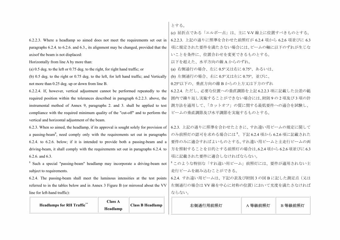
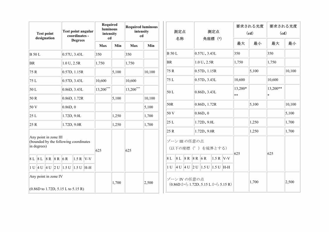
6.2.4. The passing-beam shall meet the luminous intensities at the test points
referred to in the tables below and in Annex 3 Figure B (or mirrored about the VV
line for left-hand traffic):
6.2.4. すれ違い用ビームは、下記の表及び附則 3 の図 B に記した測定点(又は
左側通行の場合は VV 線を中心に対称の位置)において光度を満たさなければ
ならない。
Headlamps for RH Traffic** Class A
Headlamp Class B Headlamp 右側通行用前照灯 A 等級前照灯 B 等級前照灯
Test point designation
Test point angular coordinates -
Degrees
Required luminous intensity
cd
Required luminous intensity
cd
Max Min Max Min
B 50 L 0.57U, 3.43L 350 350
BR 1.0 U, 2.5R 1,750 1,750
75 R 0.57D, 1.15R 5,100 10,100
75 L 0.57D, 3.43L 10,600 10,600
50 L 0.86D, 3.43L 13,200*** 13,200***
50 R 0.86D, 1.72R 5,100 10,100
50 V 0.86D, 0 5,100
25 L 1.72D, 9.0L 1,250 1,700
25 R 1.72D, 9.0R 1,250 1,700
Any point in zone III (bounded by the following coordinates in degrees)
625 625
8 L 8 L 8 R 8 R 6 R 1.5 R V-V
1 U 4 U 4 U 2 U 1.5 U 1.5 U H-H
Any point in zone IV
(0.86D to 1.72D, 5.15 L to 5.15 R) 1,700 2,500
測定点
名称
測定点
角座標(°)
要求される光度
(cd)
要求される光度
(cd)
最大 最小 最大 最小
B 50 L 0.57U、3.43L 350 350
BR 1.0 U、2.5R 1,750 1,750
75 R 0.57D、1.15R 5,100 10,100
75 L 0.57D、3.43L 10,600 10,600
50 L 0.86D、3.43L 13,200*
**
13,200**
*
50R 0.86D、1.72R 5,100 10,100
50 V 0.86D、0 5,100
25 L 1.72D、9.0L 1,250 1,700
25 R 1.72D、9.0R 1,250 1,700
ゾーン III の任意の点
(以下の座標(°)を境界とする)
625 625 8 L 8 L 8 R 8 R 6 R 1.5 R V-V
1 U 4 U 4 U 2 U 1.5 U 1.5 U H-H
ゾーン IV の任意の点
(0.86Dから1.72D、5.15 Lから5.15 R) 1,700 2,500

Any point in zone I
(1.72D to 4D, 9 L to 9 R) 17,600 < 2I*
ゾーン I の任意の点
(1.72D から 4D、9L から 9R)
17,600 <2I*
Note: In the table:
Letter L means that the point is located on the left of VV line.
Letter R means that the point is located on the right of VV line.
Letter U means the point is located above HH line
Letter D means the point or segment is located below HH line
* Actual measured value at points 50R / 50L respectively
** For left-hand traffic, the letter R shall be replaced by letter L and vice versa.
*** In case where a headlamp in which LED modules are producing a passing-beam
in conjunction with an electronic light source control gear, the measured value shall
not be more than 18,500 cd.
注:表中:
文字 L は、点が VV 線の左側にあることを意味する。
文字 R は、点が VV 線の右側にあることを意味する。
文字 U は、点が HH 線より上にあることを意味する。
文字 D は、点又はセグメントが HH 線より下にあることを意味する。
*点 50R/50L におけるそれぞれの実測値。
**左側通行用については、文字 R を文字 L に、文字 L を文字 R に置き換える
ものとする。
***LED モジュールが電子式光源制御装置とともにすれ違い用ビームを発す
る前照灯の場合は、測定値が 18,500cd を超えないものとする。
Headlamps for RH Traffic**
Test point Angular coordinates
Degrees
Required luminous intensity- cd
Min
1 4U, 8L Points 1+2+3
190 2 4U, 0
3 4U, 8R
4 2U, 4L Points 4+5+6
375 5 2U, 0
6 2U, 4R
7 0, 8L 65
右側通行用前照灯**
測定点 角座標(°)
要求される光度(cd)
最小
1 4U、8L 測定点 1+2+3
190 2 4U、0
3 4U、8R
4 2U、4L 測定点 4+5+6
375 5 2U、0
6 2U、4R
7 0、8L 65
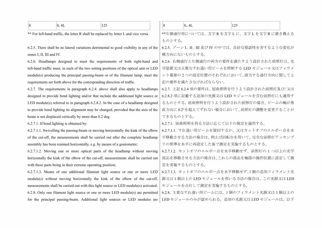
8 0, 4L 125
8 0、4L 125
** For left-hand traffic, the letter R shall be replaced by letter L and vice versa. **左側通行用については、文字 R を文字 L に、文字 L を文字 R に置き換える
ものとする。
6.2.5. There shall be no lateral variations detrimental to good visibility in any of the
zones I, II, III and IV.
6.2.5. ゾーン I、II、III 及び IV の中では、良好な視認性を害するような変化が
横方向にないものとする。
6.2.6. Headlamps designed to meet the requirements of both right-hand and
left-hand traffic must, in each of the two setting positions of the optical unit or LED
module(s) producing the principal passing-beam or of the filament lamp, meet the
requirements set forth above for the corresponding direction of traffic.
6.2.6. 右側通行と左側通行の両方の要件を満たすよう設計された前照灯は、光
学装置又は主要なすれ違い用ビームを照射する LED モジュール又はフィラメ
ント電球の 2 つの設定位置のそれぞれにおいて、該当する通行方向に関して上
記の要件を満たさなければならない。
6.2.7. The requirements in paragraph 6.2.4. above shall also apply to headlamps
designed to provide bend lighting and/or that include the additional light source or
LED module(s) referred to in paragraph 6.2.8.2. In the case of a headlamp designed
to provide bend lighting its alignment may be changed, provided that the axis of the
beam is not displaced vertically by more than 0.2 deg.
6.2.7. 上記 6.2.4 項の要件は、屈曲照明を行うよう設計された前照灯及び/又は
6.2.8.2 項に記載する追加の光源又は LED モジュールを含む前照灯にも適用す
るものとする。屈曲照明を行うよう設計された前照灯の場合、ビームの軸が垂
直方向に 0.2°を超えてずれない場合において、前照灯の調整を変更することが
できるものとする。
6.2.7.1. If bend lighting is obtained by: 6.2.7.1. 屈曲照明を得る方法に応じて以下の規定を適用する。
6.2.7.1.1. Swivelling the passing-beam or moving horizontally the kink of the elbow
of the cut-off, the measurements shall be carried out after the complete headlamp
assembly has been reaimed horizontally, e.g. by means of a goniometer;
6.2.7.1.1. すれ違い用ビームを旋回するか、又はカットオフのエルボー点を水
平移動させる方法の場合は、例えば回転台を用いて、完全な前照灯アッセンブ
リの照準を水平に再設定した後で測定を実施するものとする。
6.2.7.1.2. Moving one or more optical parts of the headlamp without moving
horizontally the kink of the elbow of the cut-off, measurements shall be carried out
with these parts being in their extreme operating position;
6.2.7.1.2. カットオフのエルボー点を水平移動せず、前照灯の 1 つ以上の光学
部品を移動させる方法の場合は、これらの部品を極限の操作位置に設定して測
定を実施するものとする。
6.2.7.1.3. Means of one additional filament light source or one or more LED
module(s) without moving horizontally the kink of the elbow of the cut-off,
measurements shall be carried out with this light source or LED module(s) activated.
6.2.7.1.3. カットオフのエルボー点を水平移動せず、1 個の追加フィラメント光
源又は 1 個以上の LED モジュールを用いる方法の場合は、この光源又は LED
モジュールを点灯して測定を実施するものとする。
6.2.8. Only one filament light source or one or more LED module(s) are permitted
for the principal passing-beam. Additional light sources or LED modules are
6.2.8. 主要なすれ違い用ビームには、1 個のフィラメント光源又は 1 個以上の
LED モジュールのみが認められる。追加の光源又は LED モジュールは、以下
permitted only as follows (see Annex 10): の場合に限り認められるものとする(附則 10 を参照)。
6.2.8.1. One additional light source according to Regulation No. 37 or one or more
additional LED module(s) may be used inside the passing-beam headlamp to
contribute to bend lighting;
6.2.8.1. 屈曲照明に寄与するために、すれ違い用ビーム前照灯内で、協定規則
第 37 号に基づく 1 個の追加光源、又は 1 個以上の追加 LED モジュールを使用
することができる。
6.2.8.2. One additional light source according to Regulation No. 37 and/or one or
more LED module(s), inside the passing-beam headlamp, may be used for the
purposes of generating infrared radiation. It/they shall only be activated at the same
time as the principal light source or LED module(s). In the event that the
principal light source or (one of) the principal LED module(s) fails, this additional
light source and/or LED module(s) shall be automatically switched off;
6.2.8.2. 赤外放射するために、すれ違い用ビーム前照灯内で、協定規則第 37
号に基づく 1 個の追加光源、及び/又は 1 個以上の LED モジュールを使用する
ことができる。これらは、主要な光源又は LED モジュールと同時のときに限
り点灯するものとする。主要な光源又は主要な LED モジュールのうちの 1 個
でも故障した場合には、この追加光源及び/又は LED モジュールは自動的に消
灯するものとする。
6.2.8.3. In the event of failure of an additional filament light source or one or more
additional LED module(s), the headlamp shall continue to fulfil the requirements of
the passing-beam.
6.2.8.3. 追加フィラメント光源又は 1個以上の追加LEDモジュールが故障した
場合でも、前照灯は引き続きすれ違い用ビームの要件を満たすものとする。
6.3. Provisions concerning driving-beams 6.3. 主走行ビームに関する規定
6.3.1. In the case of a headlamp designed to provide a driving-beam and a
passing-beam, measurements of the luminous intensity of the driving-beam shall be
taken with the same headlamp alignment as for measurements under paragraphs
6.2.4. to 6.2.6. above; in the case of a headlamp providing a driving-beam only, it
shall be so adjusted that the area of maximum luminous intensity is centred on the
point of intersection of lines H-H and V-V; such a headlamp need meet only
the requirements referred to in paragraph 6.3. Where more than one light source is
used to provide the driving-beam, the combined functions shall be used to determine
the maximum value of the luminous intensity (IM).
6.3.1. 主走行ビームとすれ違い用ビームを提供するように設計されている前
照灯の場合には、主走行ビームの光度の測定は、前照灯の調整を上記 6.2.4 項
から 6.2.6 項に基づく測定の場合と同様にして行うものとする。主走行ビーム
のみを提供する前照灯の場合には、線 H-H と線 V-V の交点が最大光度部分の
中心となるように調整するものとする。かかる前照灯は、6.3 項に記す要件の
みを満たす必要がある。主走行ビームを提供するために 2 個以上の光源が使用
されている場合は、光度の最大値(IM)を求めるために結合された機能を用い
るものとする。
6.3.2. Irrespective of the type of light source (LED module(s) or filament light
source(s)) used to produce the principal passing-beam, several light sources:
(a) Either filament light sources listed in Regulation No. 37; or
6.3.2. 主要なすれ違い用ビームを提供するために使用する光源(LED モジュー
ル又はフィラメント光源)の種類を問わず、各個別の主走行ビームには、以下
のいずれかの光源を複数個使用してもよい。
(a) 協定規則第 37 号に規定されたフィラメント光源
(b) LED module(s) may be used for each individual driving-beam. (b) LED モジュール
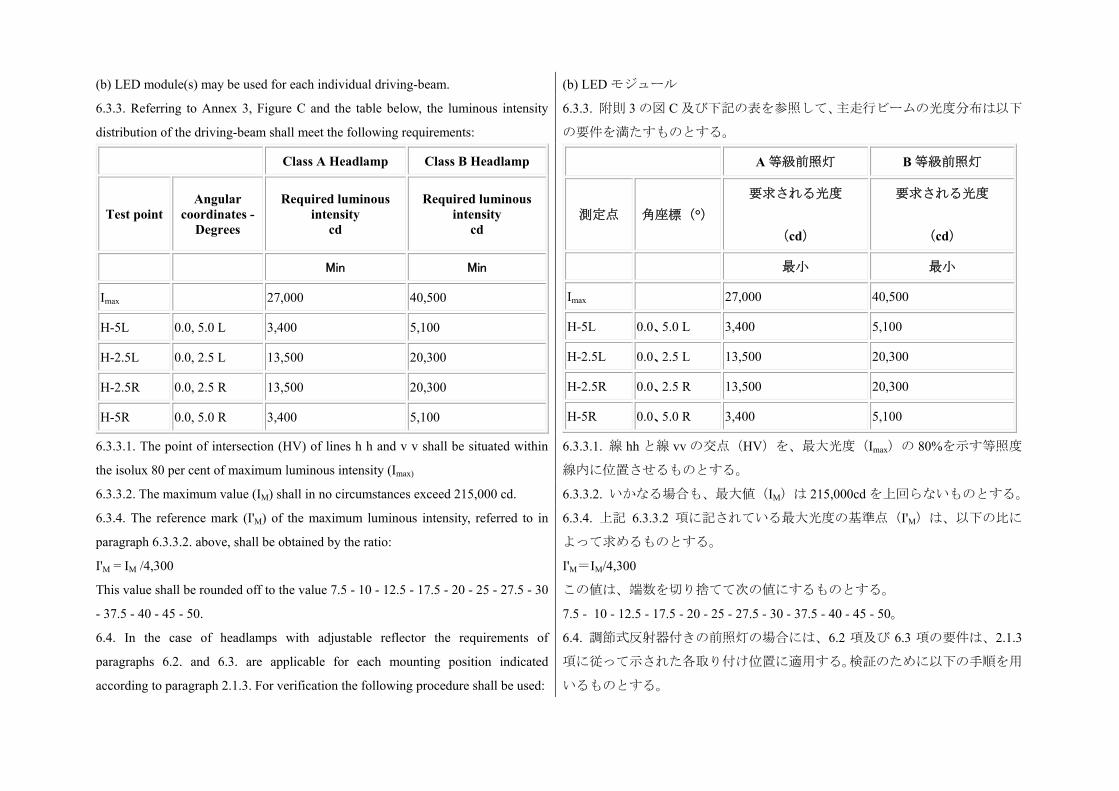
6.3.3. Referring to Annex 3, Figure C and the table below, the luminous intensity
distribution of the driving-beam shall meet the following requirements:
6.3.3. 附則 3 の図 C 及び下記の表を参照して、主走行ビームの光度分布は以下
の要件を満たすものとする。
Class A Headlamp Class B Headlamp
Test point Angular
coordinates - Degrees
Required luminous intensity
cd
Required luminous intensity
cd
Min Min
Imax 27,000 40,500
H-5L 0.0, 5.0 L 3,400 5,100
H-2.5L 0.0, 2.5 L 13,500 20,300
H-2.5R 0.0, 2.5 R 13,500 20,300
H-5R 0.0, 5.0 R 3,400 5,100
A 等級前照灯 B 等級前照灯
測定点 角座標(°)要求される光度
(cd)
要求される光度
(cd)
最小 最小
Imax 27,000 40,500
H-5L 0.0、5.0 L 3,400 5,100
H-2.5L 0.0、2.5 L 13,500 20,300
H-2.5R 0.0、2.5 R 13,500 20,300
H-5R 0.0、5.0 R 3,400 5,100
6.3.3.1. The point of intersection (HV) of lines h h and v v shall be situated within
the isolux 80 per cent of maximum luminous intensity (Imax)
6.3.3.1. 線 hh と線 vv の交点(HV)を、最大光度(Imax)の 80%を示す等照度
線内に位置させるものとする。
6.3.3.2. The maximum value (IM) shall in no circumstances exceed 215,000 cd. 6.3.3.2. いかなる場合も、最大値(IM)は 215,000cd を上回らないものとする。
6.3.4. The reference mark (I'M) of the maximum luminous intensity, referred to in
paragraph 6.3.3.2. above, shall be obtained by the ratio:
I'M = IM /4,300
This value shall be rounded off to the value 7.5 - 10 - 12.5 - 17.5 - 20 - 25 - 27.5 - 30
- 37.5 - 40 - 45 - 50.
6.3.4. 上記 6.3.3.2 項に記されている最大光度の基準点(I'M)は、以下の比に
よって求めるものとする。
I'M=IM/4,300
この値は、端数を切り捨てて次の値にするものとする。
7.5 - 10 - 12.5 - 17.5 - 20 - 25 - 27.5 - 30 - 37.5 - 40 - 45 - 50。
6.4. In the case of headlamps with adjustable reflector the requirements of
paragraphs 6.2. and 6.3. are applicable for each mounting position indicated
according to paragraph 2.1.3. For verification the following procedure shall be used:
6.4. 調節式反射器付きの前照灯の場合には、6.2 項及び 6.3 項の要件は、2.1.3
項に従って示された各取り付け位置に適用する。検証のために以下の手順を用
いるものとする。

6.4.1. Each applied position is realized on the test goniometer with respect to a line
joining the centre of the light source and point HV on a aiming screen. The
adjustable reflector is then moved into such a position that the light pattern on the
screen corresponds to the aiming prescriptions of paragraphs 6.2.1. to 6.2.2.3.
and/or 6.3.1.;
6.4.1. 該当する各位置を、照準調整スクリーン上の点 HV と光源の中心とを結
ぶ直線に関して、試験用回転台上で決定する。次に、スクリーン上の配光パタ
ーンが 6.2.1 から 6.2.2.3 項及び/又は 6.3.1 項の照準規定に一致する位置に調節
式反射器を移動させる。
6.4.2. With the reflector initially fixed according to paragraph 6.4.1., the headlamp
must meet the relevant photometric requirements of paragraphs 6.2. and 6.3.;
6.4.2. 当初は反射器を 6.4.1 項に従って固定した状態で、前照灯が 6.2 項及び
6.3 項の該当する配光要件に適合しなければならない。
6.4.3.
Additional tests are made after the reflector has been moved vertically +/-2 deg. or
at least into the maximum position, if less than 2 deg., from its initial position by
means of the headlamps adjusting device. Having re-aimed the headlamp as a whole
(by means of the goniometer for example) in the corresponding opposite direction
the light output in the following directions shall be controlled and lie within the
required limits:
passing-beam : points HV and 75 R (75 L respectively);
driving-beam : IM and point HV (percentage of IM).
6.4.3. 前照灯調整装置を使って、反射器を当初の位置から±2°、又は少なくと
も最大の位置(2°より小さい場合)まで垂直方向に動かした後、追加試験を行
うものとする。次に、前照灯全体の照準をその反対方向に再度合わせ(例えば
回転台を用いて)、以下の方向への光の出力を制御し、要求される限度内に位
置させるようにするものとする。
すれ違い用ビーム:点 HV と 75R(75L、各々に応じて)、
主走行ビーム:IMと点 HV(IMの百分率)。
6.4.4. If the applicant has not indicated more than one mounting position, the
procedure of paragraphs 6.4.1. to 6.4.3. shall be repeated for all other positions;
6.4.4. 申請者が複数の取り付け位置を示していない場合には、6.4.1項から 6.4.3
項の手順を他のすべての位置につき繰り返すものとする。
6.4.5. If the applicant has not asked for special mounting positions, the headlamp
shall be aimed for measurements of paragraphs 6.2. and 6.3. with the headlamps
adjusting device in its mean position.
The additional test of paragraph 6.4.3. shall be made with the reflector moved into
its extreme positions (instead of +/-2 deg.) by means of the headlamps adjusting
device.
6.4.5. 申請者が特別な取り付け位置を求めていない場合には、前照灯は、前照
灯調節装置を中間位置に設定した状態で、6.2 及び 6.3 項の測定のために照準
を合わせるものとする。
6.4.3 項の追加試験は、前照灯調節装置を使って反射器を(±2°
ではなく)極限位置に移動して実施するものとする。
7. Colour 7. 色
7.1. The colour of the light emitted shall be white. 7.1. 照射される光の色は白とする。
8. Gauging of discomfort
The discomfort caused by the passing-beam of headlamps shall be gauged9. 9 This requirement will be the subject of a recommendation to administrations.
8. 不快度の測定
前照灯のすれ違い用ビームによって発生する不快度を測定するものとする。9
9本要件は、行政官庁への勧告の対象となる。
C. Further administrative provisions C. 追加行政規定
9. Modification of the headlamp type and extension of approval 9. 前照灯型式の変更及び認可の拡大
9.1. Every modification of the headlamp type shall be notified to the Type Approval
Authority which approved the headlamp type. The said Authority may then either:
9.1. 前照灯型式を変更した場合はすべて、当該前照灯型式を認可した行政官庁
に届け出るものとする。通知を受けた官庁は次に下記のいずれかの措置を講ず
る。
9.1.1. Consider that the modifications made are unlikely to have appreciable adverse
effects and that in any event the headlamp still complies with the requirements;
Or
9.1.1. 加えられた変更は著しい悪影響を及ぼす恐れがなく、いずれの場合にお
いても前照灯が要件に適合していることに変わりがないと判断する。又は、
9.1.2. Require a further test report from the Technical Service responsible for
conducting the tests.
9.1.2. 試験の実施を担当する技術機関に追加の試験成績書を要求する。
9.2. Confirmation or refusal of approval, specifying the alterations, shall be
communicated by the procedure specified in paragraph 4.1.4. above to the Parties to
the Agreement which apply this Regulation.
9.2. 認可の確認又は拒否は、変更箇所を明記したうえで、上記 4.1.4 項に規定
した手順によって、本規則を適用する締約国に通知するものとする。
9.3. The competent Authority issuing the extension of approval shall assign a series
number to each communication form drawn up for such an extension and inform
thereof the other Parties to the 1958 Agreement applying this Regulation by means
of a communication form conforming to the model in Annex 1 to
this Regulation.
9.3. 認可の拡大を付与する所管官庁は、当該拡大に関して作成された各通知書
に通し番号を割り当て、本規則附則 1 のひな形に準拠する通知書によって、本
規則を適用する他の 1958 年協定加盟
国にこれを通知するものとする。
10. Conformity of production
The conformity of production procedures shall comply with those set out in the
10. 生産の適合性
生産の適合性手順は本協定の付録 2(E/ECE/324-E/ECE/TRANS/505/Rev.2)に

Agreement, Appendix 2 (E/ECE/324-E/ECE/TRANS/505/Rev.2) with the following
requirements:
定める手順並びに以下の要件に従うものとする。
10.1. Headlamps approved under this Regulation shall be so manufactured as to
conform to the type approved by meeting the requirements set forth in paragraphs 6.
and 7.
10.1. 本規則に基づいて認可された各前照灯は、6 項及び 7 項に定めた要件を
満たすことによって、認可された型式に適合するよう製造するものとする。
10.2. The minimum requirements for conformity of production control procedures
set forth in Annex 5 to this Regulation shall be complied with.
10.2. 本規則の附則 5 に定める生産の適合性管理手順に関する最小要件に適合
するものとする。
10.3. The minimum requirements for sampling by an inspector set forth in Annex 7
to this Regulation shall be complied with.
10.3. 本規則の附則 7 に定める検査官による抜取検査に関する最低要件に適合
するものとする。
10.4. The authority which has granted type approval may at any time verify the
conformity control methods applied in each production facility. The normal
frequency of these verifications shall be once every two years.
10.4. 型式認可を付与した当局は、各生産施設に適用されている適合性管理方
法をいつでも確認することができる。この検査の通常の頻度は、2 年に 1 回と
する。
10.5. Headlamps with apparent defects are disregarded. 10.5. 明らかな瑕疵のある前照灯は考慮の対象外とする。
10.6. The reference mark is disregarded. 10.6. 基準点は考慮の対象外とする。
10.7. The measuring points 1 to 8 from paragraph 6.2.4. of this Regulation are
disregarded.
10.7. 本規則の 6.2.4 項の測定点 1 から 8 は考慮の対象外とする。
11. Penalties for non-conformity of production 11. 生産の不適合に対する罰則
11.1. The approval granted in respect of a type of headlamp pursuant to this
Regulation may be withdrawn if the requirements are not complied with or if a
headlamp bearing the approval mark does not conform to the type approved.
11.1. 本規則に基づいて前照灯の型式に関して付与された認可は、要件が満た
されない場合又は認可マークを貼付した前照灯が認可された型式に適合しな
い場合には取り消すことができる。
11.2. If a Contracting Party to the Agreement applying this Regulation withdraws an
approval it has previously granted, it shall forthwith so notify the other Contracting
Parties applying this Regulation by means of a communication form conforming to
the model in Annex 1 to this Regulation.
11.2. 本規則を適用する協定加盟国が既に付与した認可を取り消す場合には、
本規則の附則 1 のひな形に準拠する通知書によって本規則を適用する他の締
約国にその旨を直ちに通知するものとする。
12. Production definitively discontinued 12. 生産中止

If the holder of the approval completely ceases to manufacture a type of headlamp
approved in accordance with this Regulation, he shall so inform the authority which
granted the approval. Upon receiving the relevant communication, that authority
shall inform thereof the other Parties to the 1958 Agreement applying this
Regulation by means of a communication form conforming to the model in Annex 1
to this Regulation.
認可を受けた者が本規則に従って認可された前照灯型式の製造を完全に中止
する場合には、認可を付与した官庁にその旨通知するものとする。通知を受け
た官庁は、本規則の附則 1 のひな形に準拠する通知書によって、本規則を適用
する他の 1958 年協定締約国にその旨通知するものとする。
13. Names and addresses of Technical Services responsible for conducting
approval tests and of Type Approval Authorities
The Parties to the 1958 Agreement applying this Regulation shall communicate to
the United Nations Secretariat the names and addresses of the Technical Services
responsible for conducting approval tests and of the Type Approval Authorities
which grant approval and to which forms certifying approval or extension or refusal
or withdrawal of approval, or production definitively discontinued, issued in other
countries, are to be sent.
13. 認可試験の実施を担当する技術機関並びに行政官庁の名称と所在地
本規則を適用する 1958 年協定締約国は、認可試験の実施を担当する技術機関、
並びに、認可を付与し、かつ他国で発行された認可又は認可の拡大若しくは拒
否若しくは取消、又は生産中止を証明する書式の送付先である行政官庁の名称
と所在地を国連事務局へ通知するものとする。
14. Transitional provisions 14. 過渡規定
14.1. From the date of entry into force of the 01 series of amendments to this
Regulation, no Contracting Party applying it shall refuse to grant approvals under
this Regulation as amended by the 01 series of amendments.
14.1. 本規則の第 1 改訂版の発効日より、本規則を適用する締約国は、第 1 改
訂版により改訂された本規則に基づく認可の付与を拒否してはならない。
14.2. Until 60 months after the date of entry into force of the 01 series of
amendments to this Regulation with regard to the changes introduced by the 01
series of amendments concerning the photometric testing procedures involving the
use of the spherical coordinate system and the specification of luminous intensity
values, and in order to allow the Technical Services to update their testing
equipment, no Contracting Party applying this Regulation shall refuse to grant
approvals under this Regulation as amended by the 01 series of amendments where
14.2. 本規則の第 1 改訂版の発効日から 60 カ月後まで、球面座標系の使用及び
配光測定値の仕様を含む光度試験手順に係る本規則第 1 改訂版によって導入
される変更に関して、かつ技術機関がその試験装置を更新できるようにするた
めに、本規則を適用するいずれの締約国も、型式認可の責任を有する当局が納
得する程度において、値を適切に変換して既存の試験装置を使用する場合は、
第 1 改訂版で改訂された本規則に基づいて認可を付与することを拒否しては
ならない。
existing testing equipment is used with suitable conversion of the values, to the
satisfaction of the authority responsible for type approval.
14.3. As from 60 months after the date of entry into force of the 01 series of
amendments, Contracting Parties applying this Regulation shall grant approvals only
if the headlamp meets the requirements of this Regulation as amended by the 01
series of amendments.
14.3. 第 1 改訂版の発効日から 60 カ月が経過した後より、本規則を適用する締
約国は、前照灯が第 1 改訂版により改訂された本規則の要件に適合している場
合に限り、認可を付与するものとする。
14.4. Existing approvals for headlamps already granted under this Regulation before
the date of entry into force of the 01 series of amendments shall remain valid
indefinitely.
14.4. 第 1 改訂版の発効日より前に本規則に基づいて前照灯に対して既に付与
された既存の認可は、無期限に有効で有り続けるものとする。
14.5. Contracting Parties applying this Regulation shall not refuse to grant
extensions of approvals to the preceding series to this Regulation.
14.5. 本規則を適用する締約国は、本規則の旧改訂版に基づく認可の拡大を付
与することを拒否してはならない。
Annex 1
Communication
(maximum format: A4 (210 x 297 mm))
issued by: Name of administration:
附則 1
通知
(最大 A4 判(210×297mm))
発行:行政官庁名
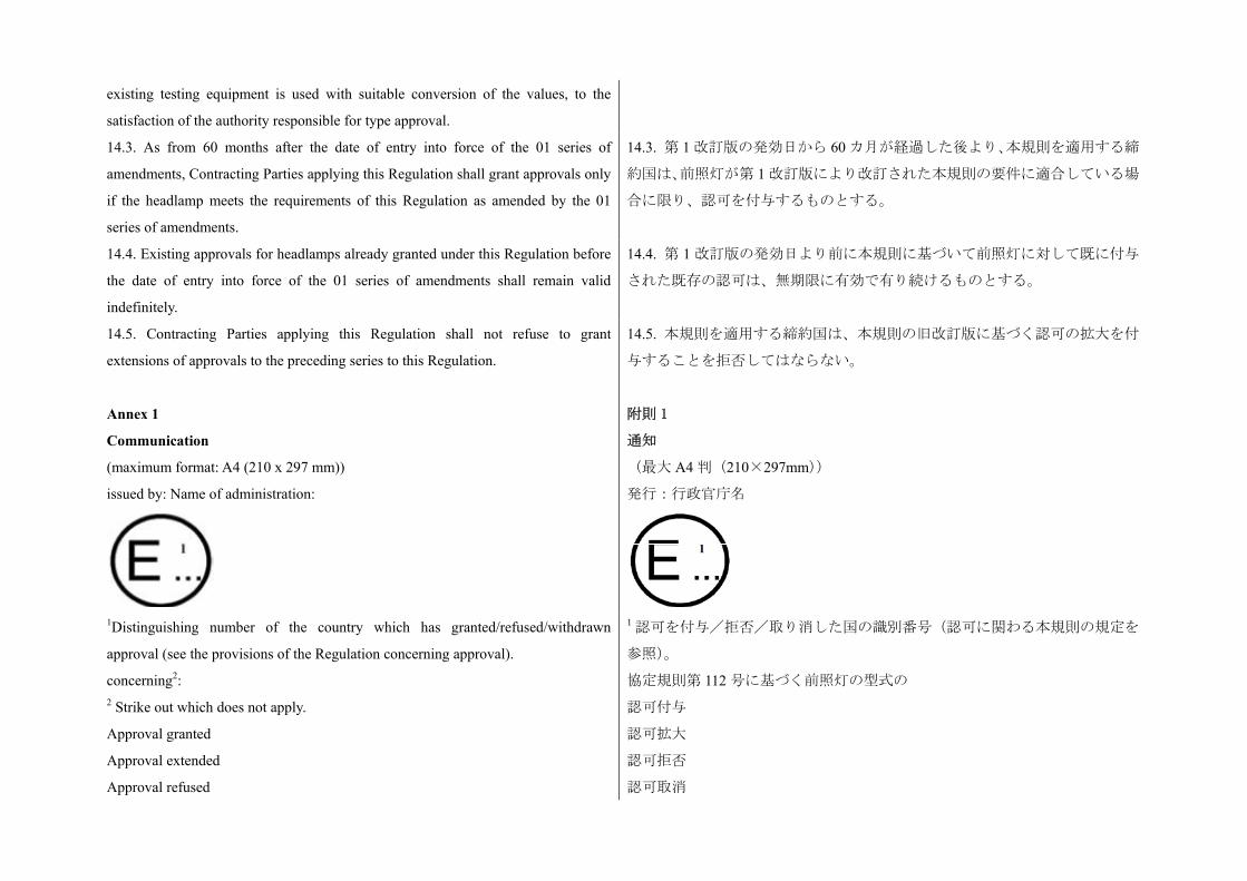
1Distinguishing number of the country which has granted/refused/withdrawn
approval (see the provisions of the Regulation concerning approval).
concerning2: 2 Strike out which does not apply.
Approval granted
Approval extended
Approval refused
1 認可を付与/拒否/取り消した国の識別番号(認可に関わる本規則の規定を
参照)。
協定規則第 112 号に基づく前照灯の型式の
認可付与
認可拡大
認可拒否
認可取消
Approval withdrawn
Production definitively discontinued
of a type of headlamp pursuant to Regulation No. 112
Approval No
Extension No
生産中止
について 2
2該当しないものを抹消する。
認可番号
拡大番号
1. Trade name or mark of the device:
2. Manufacturer's name for the type of device:
3. Manufacturer's name and address:
4. If applicable, name and address of manufacturer's representative:
5. Submitted for approval on:
6. Technical Service responsible for conducting approval tests:
7. Date of report issued by that Service:
8. Number of report issued by that Service:
1. 装置の商号又は商標
2. 装置の型式に関するメーカーの名称
3. メーカーの名称及び所在地
4. メーカーの代理人の名称及び所在地(該当する場合)
5. 認可の提出日
6. 認可試験の実施を担当する技術機関
7. 試験成績書発行日
8. 試験成績書番号
9. Brief description:
Category as described by the relevant marking3: 3 Indicate the appropriate marking selected from the list below:
9. 簡単な説明
該当する表示で表す分類区分 3
3該当する表示を以下の一覧表より選択して記す。
Number and category(s) of filament lamp(s):
Reference luminous flux used for the principal passing-beam (lm):
Principal passing-beam operated at approximately (V):
Measures according to paragraph 5.8. of this Regulation:
Number and specific identification code(s) of LED module(s) and for each LED
フィラメント電球の数及び区分
主要すれ違い用ビームについて用いた基準光束値(lm)
主要すれ違い用ビームを作動させるおおよその電圧(V)
本規則の 5.8 項に従った措置
LED モジュールの数及び特定識別コード、並びに各 LED モジュールについて
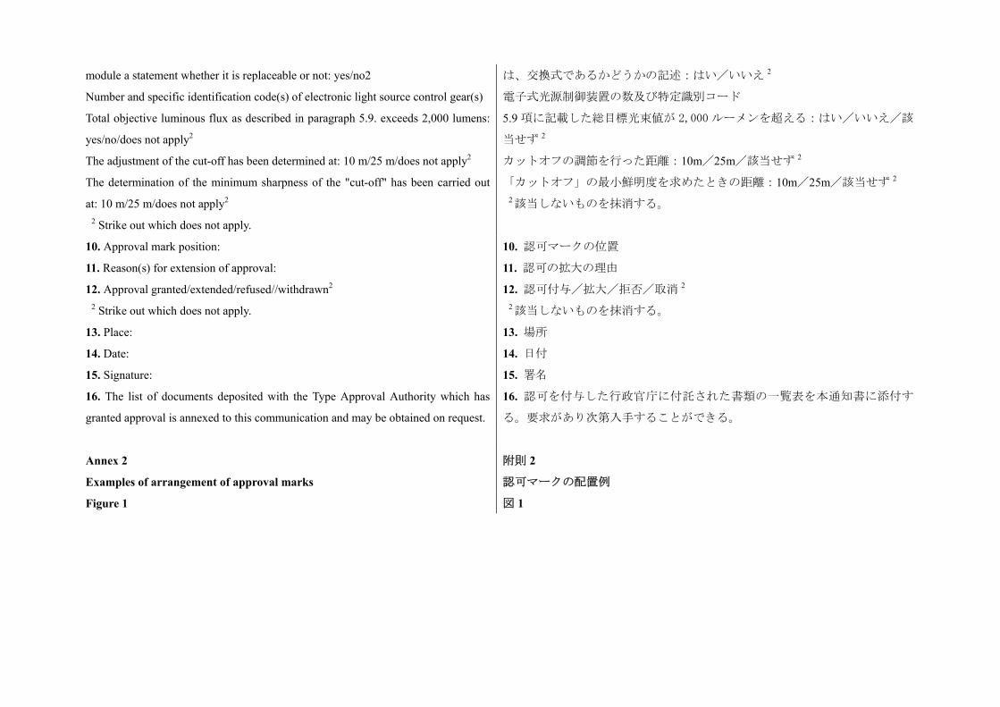
module a statement whether it is replaceable or not: yes/no2
Number and specific identification code(s) of electronic light source control gear(s)
Total objective luminous flux as described in paragraph 5.9. exceeds 2,000 lumens:
yes/no/does not apply2
The adjustment of the cut-off has been determined at: 10 m/25 m/does not apply2
The determination of the minimum sharpness of the "cut-off" has been carried out
at: 10 m/25 m/does not apply2 2 Strike out which does not apply.
は、交換式であるかどうかの記述:はい/いいえ 2
電子式光源制御装置の数及び特定識別コード
5.9 項に記載した総目標光束値が 2,000 ルーメンを超える:はい/いいえ/該
当せず 2
カットオフの調節を行った距離:10m/25m/該当せず 2
「カットオフ」の最小鮮明度を求めたときの距離:10m/25m/該当せず 2
2該当しないものを抹消する。
10. Approval mark position:
11. Reason(s) for extension of approval:
12. Approval granted/extended/refused//withdrawn2 2 Strike out which does not apply.
13. Place:
14. Date:
15. Signature:
16. The list of documents deposited with the Type Approval Authority which has
granted approval is annexed to this communication and may be obtained on request.
10. 認可マークの位置
11. 認可の拡大の理由
12. 認可付与/拡大/拒否/取消 2 2該当しないものを抹消する。
13. 場所
14. 日付
15. 署名
16. 認可を付与した行政官庁に付託された書類の一覧表を本通知書に添付す
る。要求があり次第入手することができる。
Annex 2
Examples of arrangement of approval marks
附則 2
認可マークの配置例
Figure 1 図 1

Figure 2
図 2
The headlamp bearing one of the above approval marks has been approved in the
Netherlands (E4) pursuant to Regulation No. 112 under approval number 243,
meeting the requirements of this Regulation, as amended by the 01 series of
amendments. The passing-beam is designed for right-hand traffic only. The letters
CR (Figure 1) indicate that it concerns a Class A passing and driving-beam and the
letters HCR (Figure 2) indicate that it concerns a Class B passing and driving-beam.
The figure 30 indicates that the maximum luminous intensity of the driving-beam is
between 123,625 and 145,125 candelas.
Note: The approval number and additional symbols shall be placed close to the
circle and either above or below the letter "E", or to the right or left of that letter.
上記の認可マークのいずれかを付けた前照灯は、オランダ(E4)で、協定規
則第 112 号に基づき、認可番号 243 により認可されたものであり、第 1 改訂版
によって改訂された本規則の要件に適合している。すれ違い用ビームは、右側
通行専用に設計されている。CR の文字(図 1)は A 等級のすれ違い用及び主
走行ビームに関するものであることを示しており、HCR の文字(図 2)は B
等級のすれ違い用及び主走行ビームに関するものであることを示している。
数字の 30 は、主走行ビームの最大配光測定値が 123,625 から 145,125cd の間で
あることを示している。
注:認可番号及び追加記号は、円に近接して、文字「E」の上若しくは下、又
は文字「E」の右又は左に配置するものとする。認可番号の数字は、記号「E」
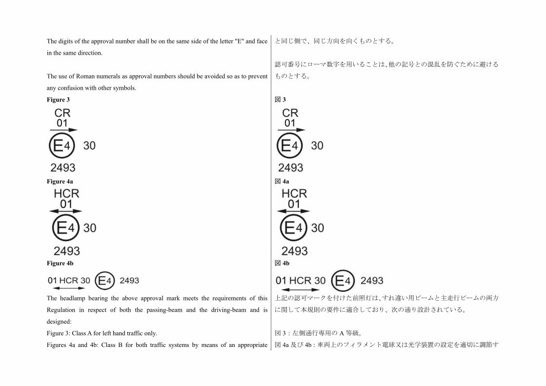
The digits of the approval number shall be on the same side of the letter "E" and face
in the same direction.
The use of Roman numerals as approval numbers should be avoided so as to prevent
any confusion with other symbols.
と同じ側で、同じ方向を向くものとする。
認可番号にローマ数字を用いることは、他の記号との混乱を防ぐために避ける
ものとする。
Figure 3
図 3
Figure 4a 図 4a
Figure 4b
図 4b
The headlamp bearing the above approval mark meets the requirements of this
Regulation in respect of both the passing-beam and the driving-beam and is
designed:
上記の認可マークを付けた前照灯は、すれ違い用ビームと主走行ビームの両方
に関して本規則の要件に適合しており、次の通り設計されている。
Figure 3: Class A for left hand traffic only.
Figures 4a and 4b: Class B for both traffic systems by means of an appropriate
図 3:左側通行専用の A 等級。
図 4a 及び 4b:車両上のフィラメント電球又は光学装置の設定を適切に調節す
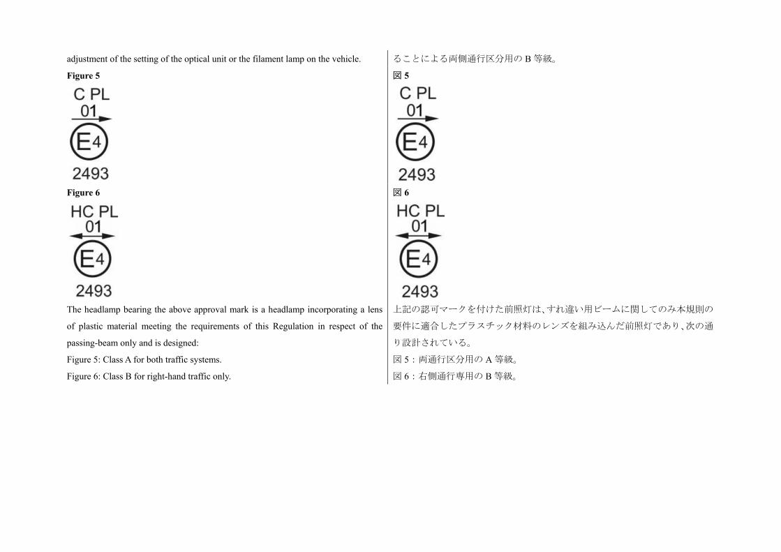
adjustment of the setting of the optical unit or the filament lamp on the vehicle. ることによる両側通行区分用の B 等級。
Figure 5
図 5
Figure 6
図 6
The headlamp bearing the above approval mark is a headlamp incorporating a lens
of plastic material meeting the requirements of this Regulation in respect of the
passing-beam only and is designed:
Figure 5: Class A for both traffic systems.
Figure 6: Class B for right-hand traffic only.
上記の認可マークを付けた前照灯は、すれ違い用ビームに関してのみ本規則の
要件に適合したプラスチック材料のレンズを組み込んだ前照灯であり、次の通
り設計されている。
図 5:両通行区分用の A 等級。
図 6:右側通行専用の B 等級。
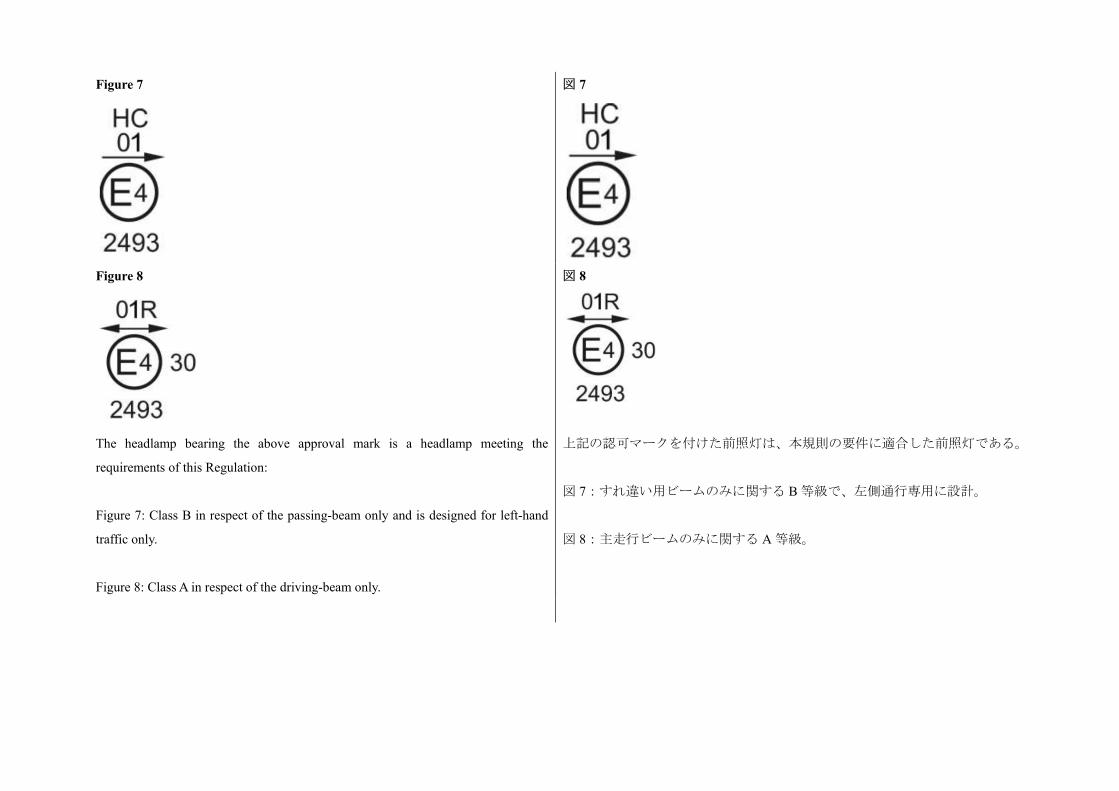
Figure 7
図 7
Figure 8
図 8
The headlamp bearing the above approval mark is a headlamp meeting the
requirements of this Regulation:
Figure 7: Class B in respect of the passing-beam only and is designed for left-hand
traffic only.
Figure 8: Class A in respect of the driving-beam only.
上記の認可マークを付けた前照灯は、本規則の要件に適合した前照灯である。
図 7:すれ違い用ビームのみに関する B 等級で、左側通行専用に設計。
図 8:主走行ビームのみに関する A 等級。
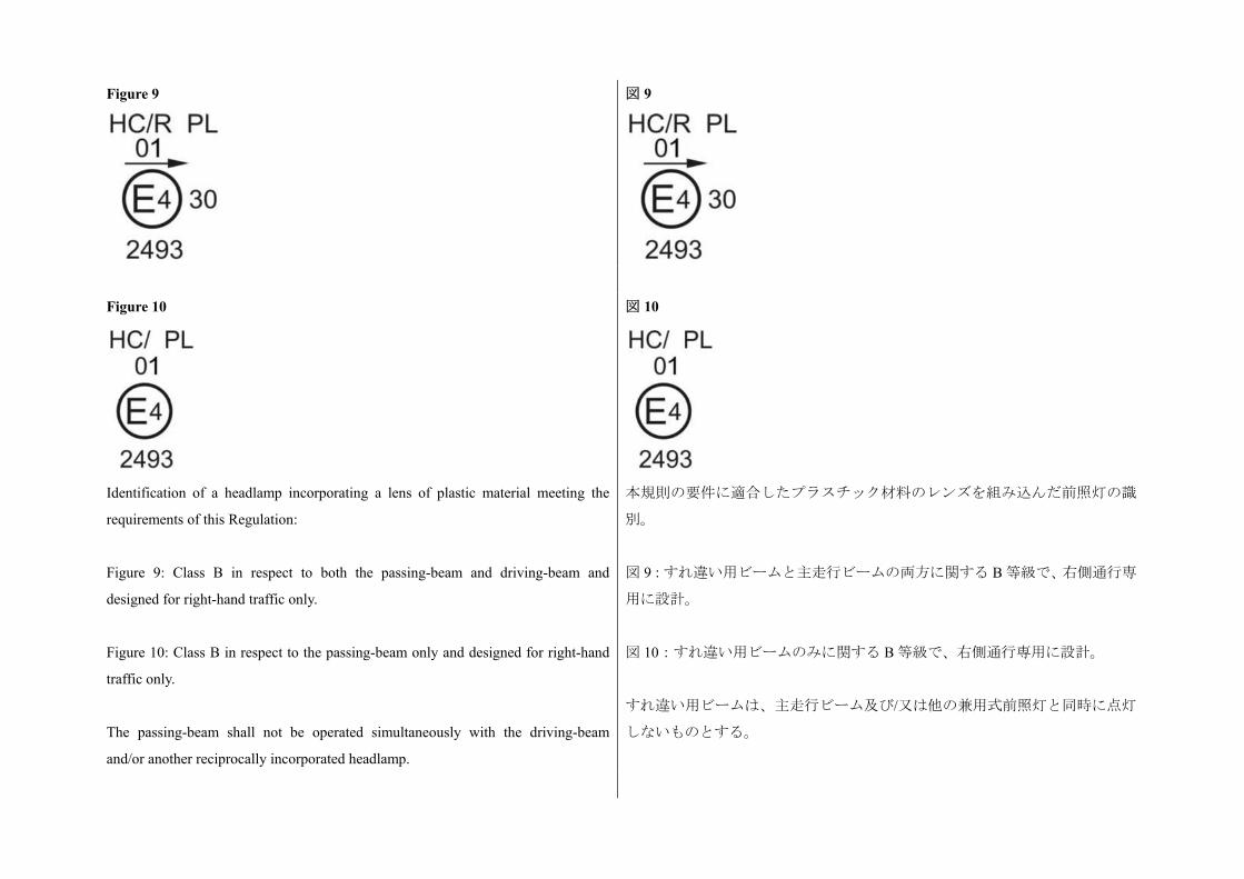
Figure 9
図 9
Figure 10
図 10
Identification of a headlamp incorporating a lens of plastic material meeting the
requirements of this Regulation:
Figure 9: Class B in respect to both the passing-beam and driving-beam and
designed for right-hand traffic only.
Figure 10: Class B in respect to the passing-beam only and designed for right-hand
traffic only.
The passing-beam shall not be operated simultaneously with the driving-beam
and/or another reciprocally incorporated headlamp.
本規則の要件に適合したプラスチック材料のレンズを組み込んだ前照灯の識
別。
図 9:すれ違い用ビームと主走行ビームの両方に関する B 等級で、右側通行専
用に設計。
図 10:すれ違い用ビームのみに関する B 等級で、右側通行専用に設計。
すれ違い用ビームは、主走行ビーム及び/又は他の兼用式前照灯と同時に点灯
しないものとする。

Figure 11: Simplified marking for grouped, combined or reciprocally
incorporated lamps
(The vertical and horizontal lines schematize the shape of the light-signalling device.
They are not part of the approval mark).
図 11:集合式、結合式又は兼用式ランプの簡略表示
(垂直線及び水平線は、灯火信号装置の形状を図式化したものであり、認可マ
ークの一部を構成するものではない)
Note: The four examples above correspond to a lighting device bearing an approval
mark comprising:
A front position lamp approved in accordance with the 02 series of amendments to
Regulation No. 7,
A headlamp, Class B, with a passing-beam designed for right- and left-hand traffic
and a driving-beam with a maximum intensity comprised between 123,625 and
145,125 candelas (as indicated by the number 30), approved in accordance with the
requirements of this Regulation, as amended by the 01 series of amendments and
注:上の 4 例は下記に関する認可マークを付けた灯火装置に相当する。
前部車幅灯:協定規則第 7 号の第 2 改訂版に従って認可されたもの。
前照灯:B 等級に属し、左右両側通行用に設計されたすれ違い用ビーム及び最
大光度が 123,625 から 145,125cd である(30 の数字で表示)主走行ビームを装
備し、第 1 改訂版によって改訂された本規則の要件に従って認可を受け、プラ
スチック材料のレンズを組み込んだもの。
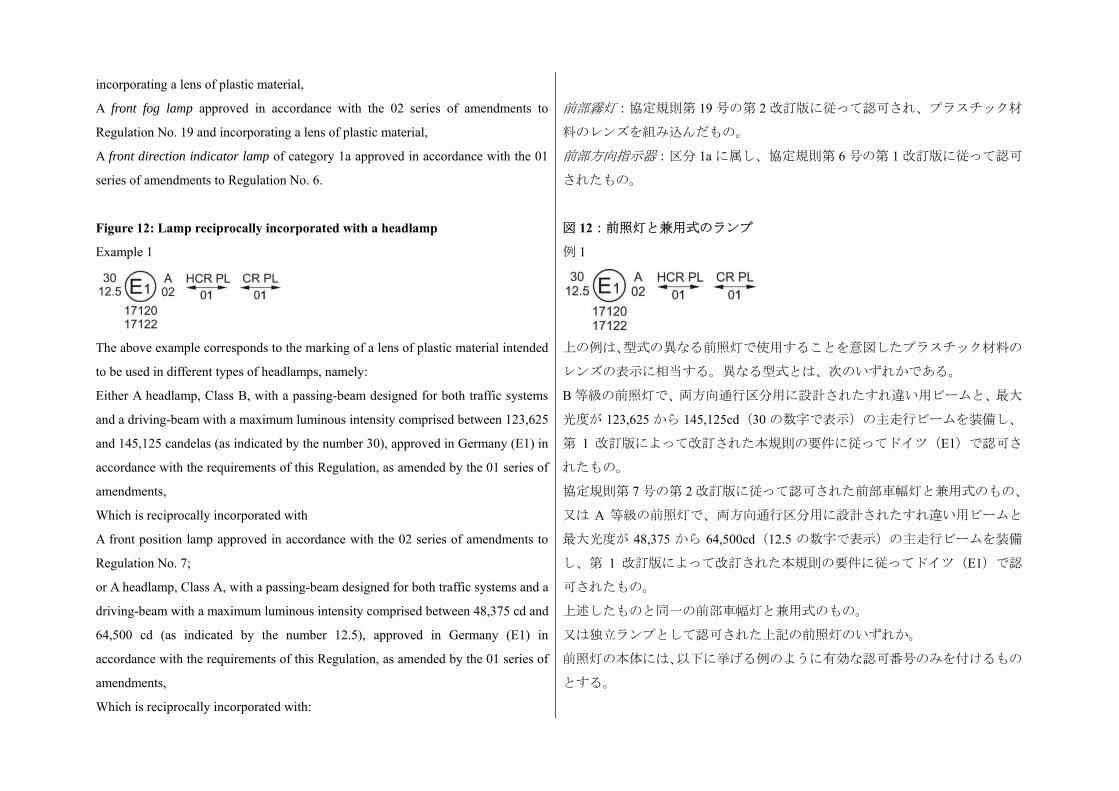
incorporating a lens of plastic material,
A front fog lamp approved in accordance with the 02 series of amendments to
Regulation No. 19 and incorporating a lens of plastic material,
A front direction indicator lamp of category 1a approved in accordance with the 01
series of amendments to Regulation No. 6.
前部霧灯:協定規則第 19 号の第 2 改訂版に従って認可され、プラスチック材
料のレンズを組み込んだもの。
前部方向指示器:区分 1a に属し、協定規則第 6 号の第 1 改訂版に従って認可
されたもの。
Figure 12: Lamp reciprocally incorporated with a headlamp
Example 1
図 12:前照灯と兼用式のランプ
例 1
The above example corresponds to the marking of a lens of plastic material intended
to be used in different types of headlamps, namely:
Either A headlamp, Class B, with a passing-beam designed for both traffic systems
and a driving-beam with a maximum luminous intensity comprised between 123,625
and 145,125 candelas (as indicated by the number 30), approved in Germany (E1) in
accordance with the requirements of this Regulation, as amended by the 01 series of
amendments,
Which is reciprocally incorporated with
A front position lamp approved in accordance with the 02 series of amendments to
Regulation No. 7;
or A headlamp, Class A, with a passing-beam designed for both traffic systems and a
driving-beam with a maximum luminous intensity comprised between 48,375 cd and
64,500 cd (as indicated by the number 12.5), approved in Germany (E1) in
accordance with the requirements of this Regulation, as amended by the 01 series of
amendments,
Which is reciprocally incorporated with:
上の例は、型式の異なる前照灯で使用することを意図したプラスチック材料の
レンズの表示に相当する。異なる型式とは、次のいずれかである。
B 等級の前照灯で、両方向通行区分用に設計されたすれ違い用ビームと、最大
光度が 123,625 から 145,125cd(30 の数字で表示)の主走行ビームを装備し、
第 1 改訂版によって改訂された本規則の要件に従ってドイツ(E1)で認可さ
れたもの。
協定規則第 7 号の第 2 改訂版に従って認可された前部車幅灯と兼用式のもの、
又は A 等級の前照灯で、両方向通行区分用に設計されたすれ違い用ビームと
最大光度が 48,375 から 64,500cd(12.5 の数字で表示)の主走行ビームを装備
し、第 1 改訂版によって改訂された本規則の要件に従ってドイツ(E1)で認
可されたもの。
上述したものと同一の前部車幅灯と兼用式のもの。
又は独立ランプとして認可された上記の前照灯のいずれか。
前照灯の本体には、以下に挙げる例のように有効な認可番号のみを付けるもの
とする。
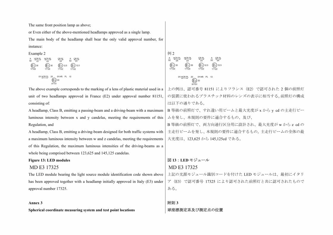
The same front position lamp as above;
or Even either of the above-mentioned headlamps approved as a single lamp.
The main body of the headlamp shall bear the only valid approval number, for
instance:
Example 2
例 2
The above example corresponds to the marking of a lens of plastic material used in a
unit of two headlamps approved in France (E2) under approval number 81151,
consisting of:
A headlamp, Class B, emitting a passing-beam and a driving-beam with a maximum
luminous intensity between x and y candelas, meeting the requirements of this
Regulation, and
A headlamp, Class B, emitting a driving-beam designed for both traffic systems with
a maximum luminous intensity between w and z candelas, meeting the requirements
of this Regulation, the maximum luminous intensities of the driving-beams as a
whole being comprised between 123,625 and 145,125 candelas.
上の例は、認可番号 81151 によりフランス(E2)で認可された 2 個の前照灯
の装置に使われるプラスチック材料のレンズの表示に相当する。前照灯の構成
は以下の通りである。
B 等級の前照灯で、すれ違い用ビームと最大光度が x から y cd の主走行ビー
ムを発し、本規則の要件に適合するもの、及び、
B 等級の前照灯で、両方向通行区分用に設計され、最大光度が w から z cd の
主走行ビームを発し、本規則の要件に適合するもの。主走行ビームの全体の最
大光度は、123,625 から 145,125cd である。
Figure 13: LED modules
The LED module bearing the light source module identification code shown above
has been approved together with a headlamp initially approved in Italy (E3) under
approval number 17325.
図 13:LED モジュール
上記の光源モジュール識別コードを付けた LED モジュールは、最初にイタリ
ア(E3)で認可番号 17325 により認可された前照灯と共に認可されたもので
ある。
Annex 3
Spherical coordinate measuring system and test point locations
附則 3
球座標測定系及び測定点の位置
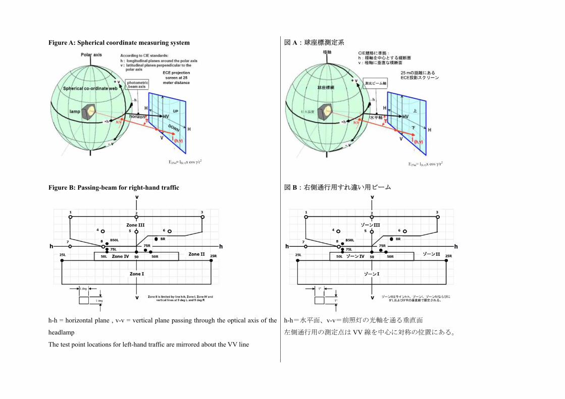
Figure A: Spherical coordinate measuring system
図 A:球座標測定系
Figure B: Passing-beam for right-hand traffic
h-h = horizontal plane , v-v = vertical plane passing through the optical axis of the
headlamp
The test point locations for left-hand traffic are mirrored about the VV line
図 B:右側通行用すれ違い用ビーム
h-h=水平面、v-v=前照灯の光軸を通る垂直面
左側通行用の測定点は VV 線を中心に対称の位置にある。
灯火装置
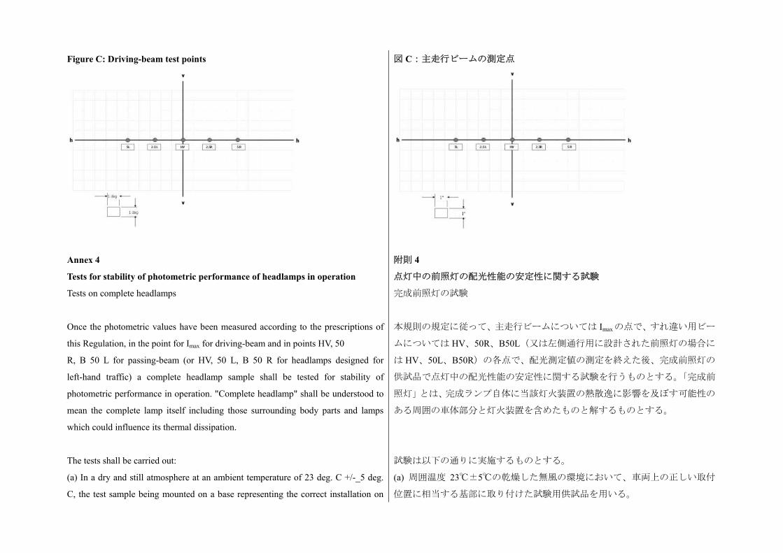
Figure C: Driving-beam test points
図 C:主走行ビームの測定点
Annex 4
Tests for stability of photometric performance of headlamps in operation
附則 4
点灯中の前照灯の配光性能の安定性に関する試験
Tests on complete headlamps
Once the photometric values have been measured according to the prescriptions of
this Regulation, in the point for Imax for driving-beam and in points HV, 50
R, B 50 L for passing-beam (or HV, 50 L, B 50 R for headlamps designed for
left-hand traffic) a complete headlamp sample shall be tested for stability of
photometric performance in operation. "Complete headlamp" shall be understood to
mean the complete lamp itself including those surrounding body parts and lamps
which could influence its thermal dissipation.
The tests shall be carried out:
(a) In a dry and still atmosphere at an ambient temperature of 23 deg. C +/-_5 deg.
C, the test sample being mounted on a base representing the correct installation on
完成前照灯の試験
本規則の規定に従って、主走行ビームについては Imaxの点で、すれ違い用ビー
ムについては HV、50R、B50L(又は左側通行用に設計された前照灯の場合に
は HV、50L、B50R)の各点で、配光測定値の測定を終えた後、完成前照灯の
供試品で点灯中の配光性能の安定性に関する試験を行うものとする。「完成前
照灯」とは、完成ランプ自体に当該灯火装置の熱散逸に影響を及ぼす可能性の
ある周囲の車体部分と灯火装置を含めたものと解するものとする。
試験は以下の通りに実施するものとする。
(a) 周囲温度 23℃±5℃の乾燥した無風の環境において、車両上の正しい取付
位置に相当する基部に取り付けた試験用供試品を用いる。
the vehicle;
(b) In case of replaceable light sources: using mass production filament light
sources, which have been aged for at least one hour, or mass production
gas-discharge light sources, which have been aged for at least 15 hours or mass
production LED modules which have been aged for at least 48 hours and cooled
down to ambient temperature before starting the tests as specified in this Regulation.
The LED modules supplied by the applicant shall be used.
The measuring equipment shall be equivalent to that used during headlamp type
approval tests.
The test sample shall be operated without being dismounted from or readjusted in
relation to its test fixture. The light source used shall be a light source of the
category specified for that headlamp.
(b) 交換式光源の場合:少なくとも 1 時間の慣らし点灯を施した量産フィラメ
ント光源、又は少なくとも 15 時間の慣らし点灯を施した量産放電灯光源、又
は少なくとも 48 時間の慣らし点灯を施した量産 LED モジュールを用いる。当
該光源は、本規則に規定された試験を開始する前に周囲温度まで冷ます。申請
者により提供された LED モジュールを用いるものとする。
測定機器は、前照灯の型式指定認可試験で使用されたものと同等とする。
試験用供試品は、試験器具から取り外したり、試験器具標識灯との位置関係を
再調整したりせずに、作動させるものとする。使用する光源は、当該前照灯に
対して規定された区分の光源とする。
1. Test for stability of photometric performance 1. 配光性能の安定性に関する試験
1.1. Clean headlamp
The headlamp shall be operated for 12 hours as described in paragraph 1.1.1. and
checked as prescribed in paragraph 1.1.2.
1.1. 汚れていない前照灯
前照灯を 1.1.1 項に記すように 12 時間点灯し、1.1.2 項に規定した通り確認す
るものとする。
1.1.1. Test procedure1 1 For the test schedule see Annex 8 to this Regulation.
The headlamp shall be operated for a period according to the specified time, so that:
1.1.1. 試験手順 1 1試験スケジュールについては、本規則の附則 8 を参照。
前照灯を所定の時間にわたり下記の条件で点灯するものとする。
1.1.1.1.
(a) In the case where only one lighting function (driving or passing-beam or front
fog lamp) is to be approved, the corresponding filament and/or LED module(s) is
(are) lit for the prescribed time2; 2 When the tested headlamp includes signalling lamps, the latter shall be lit for the
duration of the test, except for a daytime running lamp. In the case of a direction
1.1.1.1.
(a) 1 つの照明機能(主走行ビーム若しくはすれ違い用ビーム又は前部霧灯)
のみが認可される場合は、対応するフィラメント及び/又は LED モジュールを
所定時間点灯する。2 2試験対象の前照灯が標識灯を組み込んでいる場合、試験中は標識灯を点灯さ
せるものとする。ただし、デイタイムランニングランプを除く。方向指示器の
indicator lamp, it shall be lit in flashing mode with an on/ off time of approximately
one to one.
場合は、オン/オフの時間比がおよそ 1 対 1 の点滅作動モードで点灯させるも
のとする。
(b) In the case of a headlamp with a passing-beam and one or more driving-beams or
in the case of a headlamp with a passing-beam and a front fog lamp:
(b) 1 つのすれ違い用ビーム及び 1 つ以上の主走行ビームのある前照灯、又は 1
つのすれ違い用ビーム及び 1 つの前部霧灯のある前照灯の場合、
(i) The headlamp shall be subjected to the following cycle until the time specified is
reached:
15 minutes, principal passing-beam filament or principal passing-beam LED
module(s) lit;
5 minutes, all filaments and/or LED module(s) lit.
(i) 前照灯に対し、所定時間に達するまで以下のサイクルを実施するものとす
る。
15 分間、主要なすれ違い用ビームのフィラメント又は主要なすれ違い用ビー
ムの LED モジュールを点灯。
5 分間、すべてのフィラメント及び/又は LED モジュールを点灯。
(ii) If the applicant declares that the headlamp is to be used with only the
passing-beam lit or only the driving-beam(s) lit3 at a time, the test shall be carried
out in accordance with this condition, activating2 successively the passing-beam half
of the time and the driving-beam(s) (simultaneously) for half the time specified in
paragraph 1.1. above. 3 Should two or more lamp filaments and/or LED module(s) be simultaneously lit
when headlamp flashing is used, this shall not be considered as being normal use of
the filaments and/or LED module(s). 2 When the tested headlamp includes signalling lamps, the latter shall be lit for the
duration of the test, except for a daytime running lamp. In the case of a direction
indicator lamp, it shall be lit in flashing mode with an on/ off time of approximately
one to one.
(ii) 当該前照灯の使用において一度に点灯するのはすれ違い用ビームのみ又
は主走行ビームのみである 3と申請者が申告している場合、試験は、この条件
に従って、上記 1.1 項に規定された時間の半分はすれ違い用ビームを点灯し、
それに連続して残りの半分は主走行ビーム(複数ある場合は同時に)を点灯す
る 2ものとする。 3前照灯の点滅を使用するときに2つ以上のランプフィラメント及び/又はLED
モジュールを同時に点灯させる場合、これを通常のフィラメント及び/又は
LED モジュールの使用とはみなさないものとする。 2 試験対象の前照灯が標識灯を組み込んでいる場合、試験中は標識灯を点灯さ
せるものとする。ただし、デイタイムランニングランプを除く。方向指示器の
場合は、オン/オフの時間比がおよそ 1 対 1 の点滅作動モードで点灯させるも
のとする。
(c) In the case of a headlamp with a front fog lamp and one or more driving-beams: (c) 1 つの前部霧灯及び 1 つ以上の主走行ビームのある前照灯の場合、
(i) The headlamp shall be subjected to the following cycle until the time specified is
reached:
15 minutes, front fog lamp lit;
5 minutes, all filaments and/or all LED modules lit.
(i) 前照灯に対し、所定時間に達するまで以下のサイクルを実施するものとす
る。
15 分間、前部霧灯を点灯。
5 分間、すべてのフィラメント及び/又はすべての LED モジュールを点灯。
(ii) If the applicant declares that the headlamp is to be used with only the front fog (ii) 当該前照灯の使用において一度に点灯するのは前部霧灯のみ又は主走行
lamp lit or only the driving-beam(s) lit3 at a time, the test shall be carried out in
accordance with this condition, activating2 successively the front fog lamp half of
the time and the driving-beam(s) (simultaneously) for half the time specified in
paragraph 1.1. above. 3 Should two or more lamp filaments and/or LED module(s) be simultaneously lit
when headlamp flashing is used, this shall not be considered as being normal use of
the filaments and/or LED module(s). 2 When the tested headlamp includes signalling lamps, the latter shall be lit for the
duration of the test, except for a daytime running lamp. In the case of a direction
indicator lamp, itshall be lit in flashing mode with an on/ off time of approximately
one to one.
ビームのみである 3と申請者が申告している場合、試験は、この条件に従って、
上記 1.1 項に規定された時間の半分は前部霧灯を点灯し、それに連続して残り
の半分は主走行ビーム(複数ある場合は同時に)を点灯する 2ものとする。
3前照灯の点滅を使用するときに2つ以上のランプフィラメント及び/又はLED
モジュールを同時に点灯させる場合、これを通常のフィラメント及び/又は
LED モジュールの使用とはみなさないものとする。 2 試験対象の前照灯が標識灯を組み込んでいる場合、試験中は標識灯を点灯さ
せるものとする。ただし、デイタイムランニングランプを除く。方向指示器の
場合は、オン/オフの時間比がおよそ 1 対 1 の点滅作動モードで点灯させるも
のとする。
(d) In the case of a headlamp with a passing-beam, one or more driving-beams and a
front fog lamp:
(d) 1 つのすれ違い用ビーム、1 つ以上の主走行ビーム、及び 1 つの前部霧灯の
ある前照灯の場合、
(i) The headlamp shall be subjected to the following cycle until the time specified is
reached:
15 minutes, principal passing-beam filament or principal passing-beam LED
module(s) lit;
5 minutes, all filaments and/or all LED modules lit.
(i) 前照灯に対し、所定時間に達するまで以下のサイクルを実施するものとす
る。
15 分間、主要なすれ違い用ビームのフィラメント又は主要なすれ違い用ビー
ムの LED モジュールを点灯。
5 分間、すべてのフィラメント及び/又はすべての LED モジュールを点灯。
(ii) If the applicant declares that the headlamp is to be used with only the
passing-beam lit or only the driving-beam(s)3 lit at a time, the test shall be carried
out in accordance with this condition, activating2 successively the principal
passing-beam half of the time and the driving-beam(s) for half the time specified
inparagraph 1.1. above, while the front fog lamp is subjected to a cycle of 15
minutes off and 5 minutes lit for half of the time and during the operation of
thedriving-beam;
(ii) 当該前照灯の使用において一度に点灯するのはすれ違い用ビームのみ又
は主走行ビームのみである 3と申請者が申告している場合、試験は、この条件
に従って、上記 1.1 項に規定された時間の半分は主要なすれ違い用ビームを点
灯し、それに連続して残りの半分は主走行ビームを点灯し 2、その間、前部霧
灯には、当該時間の半分並びに主走行ビームの作動中に 15 分間消灯と 5 分間
点灯のサイクルを実施するものとする。
3 Should two or more lamp filaments and/or LED module(s) be simultaneously lit
when headlamp flashing is used, this shall not be considered as being normal use of
3前照灯の点滅を使用するときに2つ以上のランプフィラメント及び/又はLED
モジュールを同時に点灯させる場合、これを通常のフィラメント及び/又は
the filaments and/or LED module(s). 2 When the tested headlamp includes signalling lamps, the latter shall be lit for the
duration of the test, except for a daytime running lamp. In the case of a direction
indicator lamp, it shall be lit in flashing mode with an on/ off time of approximately
one to one.
LED モジュールの使用とはみなさないものとする。 2 試験対象の前照灯が標識灯を組み込んでいる場合、試験中は標識灯を点灯さ
せるものとする。ただし、デイタイムランニングランプを除く。方向指示器の
場合は、オン/オフの時間比がおよそ 1 対 1 の点滅作動モードで点灯させるも
のとする。
(iii) If the applicant declares that the headlamp is to be used with only the
passing-beam lit or only the front fog lamp3 lit at a time, the test shall be carried out
in accordance with this condition, activating2 successively the principal
passing-beam half of the time and the front fog lamp for half of the time specified in
paragraph 1.1. above, while the driving-beam(s) is(are) subjected to a cycle of 15
minutes off and 5 minutes lit for half of the time and during the operation of the
principal passing-beam;
3 Should two or more lamp filaments and/or LED module(s) be simultaneously lit
when headlamp flashing is used, this shall not be considered as being normal use of
the filaments and/or LED module(s).
2 When the tested headlamp includes signalling lamps, the latter shall be lit for the
duration of the test, except for a daytime running lamp. In the case of a direction
indicator lamp, it shall be lit in flashing mode with an on/ off time of approximately
one to one.
(iii) 当該前照灯の使用において一度に点灯するのはすれ違い用ビームのみ又
は前部霧灯のみである 3と申請者が申告している場合、試験は、この条件に従
って、上記 1.1項に規定された時間の半分は主要なすれ違い用ビームを点灯し、
それに連続して残りの半分は前部霧灯を点灯し 2、その間、主走行ビームには、
当該時間の半分並びに主要なすれ違い用ビームの作動中に 15 分間消灯と 5 分
間点灯のサイクルを実施するものとする。
3 前照灯の点滅を使用するときに 2 つ以上のランプフィラメント及び/又は
LED モジュールを同時に点灯させる場合、これを通常のフィラメント及び/又
は LED モジュールの使用とはみなさないものとする。
2試験対象の前照灯が標識灯を組み込んでいる場合、試験中は標識灯を点灯さ
せるものとする。ただし、デイタイムランニングランプを除く。方向指示器の
場合は、オン/オフの時間比がおよそ
1 対 1 の点滅作動モードで点灯させるものとする。
(iv) If the applicant declares that the headlamp is to be used with only the
passing-beam lit or only the driving-beam(s)3 lit or only the front fog lamp3 lit at a
time, the test shall be carried out in accordance with this condition, activating2
successively the principal passing-beam one third of the time, the drivingbeam(s)
one third of the time and the front fog lamp for one third of the time specified in
paragraph 1.1. above.
(iv)当該前照灯の使用において一度に点灯するのはすれ違い用ビームのみ又は
主走行ビームのみ 3又は前部霧灯のみ 3であると申請者が申告している場合、
試験は、この条件に従って、上記 1.1 項に規定された時間の 1/3 は主要なすれ
違い用ビームを点灯し、それに連続して次の 1/3 は主走行ビームを点灯し、残
りの 1/3 は前部霧灯を点灯する 2ものとする。
3 Should two or more lamp filaments and/or LED module(s) be simultaneously lit
when headlamp flashing is used, this shall not be considered as being normal use of
the filaments and/or LED module(s). 2 When the tested headlamp includes signalling lamps, the latter shall be lit for the
duration of the test, except for a daytime running lamp. In the case of a direction
indicator lamp, it shall be lit in flashing mode with an on/ off time of approximately
one to one.
3 前照灯の点滅を使用するときに 2 つ以上のランプフィラメント及び/又は
LED モジュールを同時に点灯させる場合、これを通常のフィラメント及び/又
は LED モジュールの使用とはみなさないものとする。 2試験対象の前照灯が標識灯を組み込んでいる場合、試験中は標識灯を点灯さ
せるものとする。ただし、デイタイムランニングランプを除く。方向指示器の
場合は、オン/オフの時間比がおよそ 1 対 1 の点滅作動モードで点灯させるも
のとする。
(e) In the case of a passing-beam designed to provide bend lighting with the addition
of a filament light source and/or one or more LED module(s), this light source
and/or LED module(s) shall be switched on for one minute, and switched off for
nine minutes during the activation of the passing-beam only (seeAnnex 4 - Appendix
1).
(e)1 個のフィラメント光源及び/又は 1 個以上の LED モジュールを追加するこ
とにより屈曲照明が行えるように設計されたすれ違い用ビームの場合には、す
れ違い用ビームのみを点灯している間、この光源及び/又は LED モジュールに
1 分間の点灯と 9 分間の消灯を行うものとする(附則 4-付録 1 を参照)。
1.1.1.2. Test voltage
The voltage shall be applied to the terminals of the test sample as follows:
(a) In case of replaceable filament light source(s) operated directly under vehicle
voltage system conditions:
The test shall be performed at 6.3 V, 13.2 V or 28.0 V as applicable except if the
applicant specifies that the test sample may be used at a different voltage. In this
case, the test shall be carried out with the filament light source operated at the
highest voltage that can be used.
(b) In case of replaceable gas discharge light source(s): The test voltage for the
electronic light source control-gear is 13.2 +/- 0.1 volts for 12 V vehicle voltage
system, or otherwise specified in the application for approval.
1.1.1.2. 試験電圧
以下の通りに試験用供試品の端子に電圧を印加するものとする。
(a) 車両電圧システムの条件下で直接作動する交換式フィラメント光源の場
合、
試験は、6.3V、13.2V 又は 28.0V(該当する電圧)において実施するものとす
る。ただし、これらと異なる電圧で試験用供試品を使用してもよいことを申請
者が指定している場合は例外とする。この場合には、試験は、使用可能な最も
高い電圧で作動させたフィラメント光源を用いて実施するものとする。
(b) 交換式放電灯光源の場合:電子式光源制御装置の試験電圧は、12V の車両
電圧システムの場合は 13.2±0.1V、あるいは認可申請書に規定された電圧とす
る。
(c) In the case of non-replaceable light source operated directly under vehicle
voltage system conditions: All measurements on lighting units equipped with
non-replaceable light sources (filament light sources and/ or others) shall be made at
6.3 V, 13.2 V or 28.0 V or at other voltages according to the vehicle voltage system
(c) 車両電圧システムの条件下で直接作動する非交換光源の場合:非交換光源
(フィラメント光源及び/又はその他)を装備した灯火装置の測定はすべて、
6.3V、13.2V 又は 28.0V あるいは申請者が指定した車両電圧システムに従った
その他の電圧(該当する電圧)において行うものとする。
as specified by the applicant respectively.
(d) In the case of light sources, replaceable or non-replaceable, being operated
independently from vehicle supply voltage and fully controlled by the system, or, in
the case of light sources supplied by a supply and operating device, the test voltages
as specified above shall be applied to the input terminals of that device. The test
laboratory may require from the manufacturer the supply and operating device or a
special power supply needed to supply the light source(s).
(d) 車両の供給電圧から独立して作動し、システムにより完全に制御されてい
る光源(交換式か非交換式かを問わない)の場合、又は給電及び操作装置によ
り給電される光源の場合、上記に規定された試験電圧を当該装置の入力端子に
印加するものとする。試験施設は、メーカーに対し、給電及び操作装置又は光
源への給電に必要となる特殊な電源供給装置を要求することができるものと
する。
(e) LED module(s) shall be measured at 6.75 V, 13.2 V or 28.0 V respectively, if not
otherwise specified within this Regulation. LED module(s) operated by an electronic
light source control gear, shall be measured as specified by the applicant.
(e) LED モジュールは、本規則に別段の規定がある場合を除き、6.75V、13.2V
又は 28.0V(該当する電圧)において測定するものとする。電子式光源制御装
置を用いて作動させる LED モジュールは、申請者により規定された通りに測
定するものとする。
(f) Where signalling lamps are grouped, combined or reciprocally incorporated into
the test sample and operating at voltages other than the nominal rated voltages of 6
V, 12 V or 24 V respectively, the voltage shall be adjusted as declared by the
manufacturer for the correct photometric functioning of that lamp.
(f) 標識灯が試験用供試品との集合式、結合式又は兼用式であり、公称定格電
圧 6V、12V 又は 24V(該当する電圧)以外の電圧で作動する場合には、当該
灯火装置が正しい配光で機能するようメーカーが指定した通りに、電圧を調節
するものとする。
1.1.2. Test results 1.1.2. 試験結果
1.1.2.1. Visual inspection
Once the headlamp has been stabilized to the ambient temperature, the headlamp
lens and the external lens, if any, shall be cleaned with a clean, damp cotton cloth. It
shall then be inspected visually; no distortion, deformation, cracking or change in
colour of either the headlamp lens or the external lens, if any, shall be noticeable.
1.1.2.1. 目視検査
前照灯が周囲温度で安定したら、前照灯のレンズと、該当する場合には外側レ
ンズを清潔な濡れた綿布で拭って、汚れをとるものとする。次に、目視検査を
行い、前照灯レンズにも、該当する場合には外側レンズにも、ゆがみ、変形、
亀裂、変色が確認されてはならない。
1.1.2.2. Photometric test:
To comply with the requirements of this Regulation, the photometric values shall be
verified in the following points:
Passing-beam:
50 R - B 50 L - 25 L for headlamps designed for right-hand traffic
50 L - B 50 R - 25 R for headlamps designed for left-hand traffic
1.1.2.2. 配光試験
本規則の要件に適合するためには、下記の各点で配光測定値を確認しなければ
ならない。
すれ違い用ビーム:
50R-B50L-25L 右側通行用に設計された前照灯の場合
50L-B50R-25R 左側通行用に設計された前照灯の場合
Driving beam: Point I max
Another aiming may be carried out to allow for any deformation of the headlamp
base due to heat (the change of the position of the cut-off line is covered in
paragraph 2. of this annex).
Except for point B 50 L, a 10 per cent discrepancy between the photometric
characteristics and the values measured prior to the test is permissible including the
tolerances of the photometric procedure. The value measured at point B 50 L shall
not exceed the photometric value measured prior to the test by more than 170 cd.
主走行ビーム:点 Imax
熱による前照灯の口金の変形を見越して、照準調整をもう一度行うことができ
るものとする(カットオフラインの位置の変化は、本附則の 2 項で取り上げ
る)。
点 B50L を除き、配光特性と試験前の測定値の差は、配光測定手順の公差も含
めて 10%であれば許容できる。点 B50L の測定値が試験前に測定された配光測
定値を上回る場合、その差は 170cd を超えてはならない。
1.2. Dirty headlamp
After being tested as specified in paragraph 1.1. above, the headlamp shall be
operated for one hour as described in paragraph 1.1.1., after being prepared as
prescribed in paragraph 1.2.1., and checked as prescribed in paragraph 1.1.2.
1.2. 汚れた前照灯
上記 1.1 項に規定した通りに試験を実施した後、1.2.1 項に規定した通りの準
備をしたうえで、前照灯を 1.1.1 項に記したように 1 時間点灯し、1.1.2 項に規
定した通りに確認するものとする。
1.2.1. Preparations of the headlamp 1.2.1. 前照灯の準備
1.2.1.1. Test mixture 1.2.1.1. 試験混合物
1.2.1.1.1. For headlamp with the outside lens in glass:
The mixture of water and a polluting agent to be applied to the headlamp shall be
composed of:
9 parts by weight of silica sand with a particle size of 0-100 micrometres,
1 part by weight of vegetal carbon dust (beechwood) with a particle size of 0-100
micrometres,
0.2 parts by weight of NaCMC4, and 4 NaCMC represents the sodium salt of carboxymethylcellulose, customarily
referred to as CMC. The NaCMC used in the dirt mixture shall have a degree of
substitution (DS) of 0.6-0.7 and a viscosity of 200-300 cP for a 2 per cent solution at
20 deg. C.
An appropriate quantity of distilled water, with a conductivity of < 1 mS/m.
The mixture must not be more than 14 days old.
1.2.1.1.1. ガラス製外側レンズ付き前照灯の場合
前照灯に塗布する水と汚染剤との混合物の組成は次の通りと
する。
粒子の大きさが 0 から 100μm の珪砂、9 重量部
粒子の大きさが 0 から 100μm の植物性炭素粉(ブナ材)、1 重量部
NaCMC4、0.2 重量部 4NaCMC は、一般には CMC と呼ばれるカルボキシメチルセルロースのナトリ
ウム塩を表す。汚泥混合物に使用するNaCMCは、20℃の 2%溶液で置換度(DS)
0.6 から 0.7、粘度 200 から 300cP を有するものとする。
伝導率 1mS/m 以下の蒸留水、適量。
この混合物は調整後 14 日以内のものでなければならない。
1.2.1.1.2.
For headlamp with outside lens in plastic material:
The mixture of water and polluting agent to be applied to the headlamp shall be
composed of:
9 parts by weight of silica sand with a particle size of 0-100 micrometres,
1 part by weight of vegetal carbon dust (beechwood) with a particle size of 0-100
micrometres,
0.2 part by weight of NaCMC4, 4 NaCMC represents the sodium salt of carboxymethylcellulose, customarily
referred to as CMC. The NaCMC used in the dirt mixture shall have a degree of
substitution (DS) of 0.6-0.7 and a viscosity of 200-300 cP for a 2 per cent solution at
20 deg. C.
13 parts by weight of distilled water with a conductivity of < 1 mS/m, and 2 +/- 1
parts by weight of surface-actant5 5 The tolerance on quantity is due to the necessity of obtaining a dirt that correctly
spreads out on all the plastic lens.
The mixture must not be more than 14 days old.
1.2.1.1.2.
プラスチック材料製外側レンズ付き前照灯の場合
前照灯に塗布する水と汚染剤との混合物の組成は次の通りとする。
粒子の大きさが 0 から 100μm の珪砂、9 重量部
粒子の大きさが 0 から 100μm の植物性炭素粉(ブナ材)、1 重量部
NaCMC4、0.2 重量部
4NaCMC は、一般には CMC と呼ばれるカルボキシメチルセルロースのナト
リウム塩を表す。汚泥混合物に使用する NaCMC は、20℃の 2%溶液で置換度
(DS)0.6 から 0.7、粘度 200 から 300cP を有するものとする。
伝導率 1mS/m 以下の蒸留水、13 重量部
表面作用剤 5、2±1 重量部 5量の公差は、全プラスチックレンズ上に適正に拡がる汚泥を作る必要による
ものである。
この混合物は調整後 14 日以内のものでなければならない。
1.2.1.2. Application of the test mixture to the headlamp
The test mixture shall be uniformly applied to the entire light-emitting surface of the
headlamp and then left to dry. This procedure shall be repeated until the illumination
value has dropped to 15-20 per cent of the values measured for each following point
under the conditions described in this annex:
Point of Emax in passing-beam/driving-beam and in driving-beam only,
50 R and 50 V6 for a headlamp producing only a passing-beam, designed for
right-hand traffic,
50 L and 50 V6 for a headlamp producing only a passing-beam, designed for
1.2.1.2. 試験混合物の前照灯への塗布
試験混合物を前照灯の発光面全体に均質に塗布して自然乾燥させるものとす
る。照度値が本附則に記した条件下で下記の各点で測定した値の 15 から 20%
に低下するまで、この手順を繰り返さなければならない。
すれ違い用ビーム/主走行ビーム及び主走行ビームだけの場合は点 Emax、
右側通行用に設計した、すれ違い用ビームのみを発する前照灯については 50R
と 50V6、
左側通行用に設計した、すれ違い用ビームのみを発する前照灯については 50L
と 50V6。
left-hand traffic. 6 Point 50 V is situated 375 mm below HV on the vertical line v-v on the screen at
25 m distance.
6 点 50V の位置は、25m 離れたスクリーンの垂直線 v-v 上の HV より下へ
375mm である。
2. Test for change in vertical position of the cut-off line under the influence of
heat
This test consists of verifying that the vertical drift of the cut-off line under the
influence of heat does not exceed a specified value for an operating headlamp
producing a passing-beam.
The headlamp tested in accordance with paragraph 1., shall be subjected to the test
described in paragraph 2.1., without being removed from or readjusted in relation to
its test fixture.
2. 熱の影響によるカットオフラインの垂直位置の変化に関する試験
この試験は、熱の影響によるカットオフラインの垂直移動が、すれ違い用ビー
ムを発する点灯中の前照灯に関する所定の値を超えないことを確認するもの
である。
1 項に基づいて試験した前照灯に対して、試験器具から取り外したりそれに関
して調節し直したりしないで、2.1 項に定める試験を行うものとする。
2.1. Test
The test shall be carried out in a dry and still atmosphere at an ambient temperature
of 23 deg. C +/-_5 deg. C.
Using a mass production filament lamp or the LED module(s) as submitted with the
headlamp, which has (have) been aged for at least one hour, the headlamp shall be
operated on the principal passing-beam without being dismounted from or
readjusted in relation to its test fixture. (For the purpose of this test, the voltage shall
be adjusted as specified in paragraph 1.1.1.2.). The position of the cut-off line in its
horizontal part (between vv and the vertical line passing through point B 50 L for
right-hand traffic or B 50 R for left-hand traffic) shall be verified 3 minutes (r3) and
60 minutes (r60) respectively after operation.
The measurement of the variation in the cut-off line position as described above
shall be carried out by any method giving acceptable accuracy and reproducible
results.
2.1. 試験
試験は、周囲温度 23℃±5℃の乾燥した無風の環境において行うものとする。
少なくとも 1 時間の慣らし点灯を施した量産フィラメント電球、又は前照灯と
共に提出された LED モジュールを使って、試験器具から取り外したりそれに
関して調節し直したりしないで、前照灯の主要なすれ違い用ビームを点灯する
ものとする(本試験の意図するところでは、電圧は 1.1.1.2 項に規定したよう
に調節するものとする)。カットオフラインの水平部分(左側通行の場合には
点 B50R、右側通行の場合には点 B50L を通る垂直線と vv の間)の位置を、点
灯 3 分後(r3)及び 60 分後(r60)にそれぞれ確認するものとする。
上に記したカットオフラインの位置の変化の測定は、受容可能な精度と再現性
のある結果が得られる任意の方法で行うものとする。
2.2. Test results 2.2. 試験結果
2.2.1. 2.2.1.
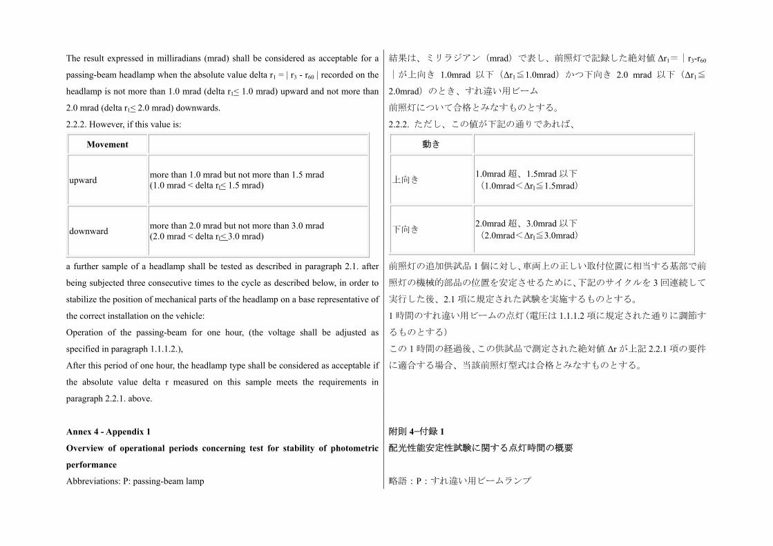
The result expressed in milliradians (mrad) shall be considered as acceptable for a
passing-beam headlamp when the absolute value delta r1 = | r3 - r60 | recorded on the
headlamp is not more than 1.0 mrad (delta r1< 1.0 mrad) upward and not more than
2.0 mrad (delta r1< 2.0 mrad) downwards.
結果は、ミリラジアン(mrad)で表し、前照灯で記録した絶対値 Δr1=|r3-r60
|が上向き 1.0mrad 以下(Δr1≦1.0mrad)かつ下向き 2.0 mrad 以下(Δr1≦
2.0mrad)のとき、すれ違い用ビーム
前照灯について合格とみなすものとする。
2.2.2. However, if this value is:
Movement
upward more than 1.0 mrad but not more than 1.5 mrad (1.0 mrad < delta rI< 1.5 mrad)
downward more than 2.0 mrad but not more than 3.0 mrad (2.0 mrad < delta rI< 3.0 mrad)
2.2.2. ただし、この値が下記の通りであれば、
動き
上向き 1.0mrad 超、1.5mrad 以下
(1.0mrad<ΔrI≦1.5mrad)
下向き 2.0mrad 超、3.0mrad 以下
(2.0mrad<ΔrI≦3.0mrad)
a further sample of a headlamp shall be tested as described in paragraph 2.1. after
being subjected three consecutive times to the cycle as described below, in order to
stabilize the position of mechanical parts of the headlamp on a base representative of
the correct installation on the vehicle:
Operation of the passing-beam for one hour, (the voltage shall be adjusted as
specified in paragraph 1.1.1.2.),
After this period of one hour, the headlamp type shall be considered as acceptable if
the absolute value delta r measured on this sample meets the requirements in
paragraph 2.2.1. above.
前照灯の追加供試品 1 個に対し、車両上の正しい取付位置に相当する基部で前
照灯の機械的部品の位置を安定させるために、下記のサイクルを 3 回連続して
実行した後、2.1 項に規定された試験を実施するものとする。
1 時間のすれ違い用ビームの点灯(電圧は 1.1.1.2 項に規定された通りに調節す
るものとする)
この 1 時間の経過後、この供試品で測定された絶対値 Δr が上記 2.2.1 項の要件
に適合する場合、当該前照灯型式は合格とみなすものとする。
Annex 4 - Appendix 1
Overview of operational periods concerning test for stability of photometric
performance
附則 4−付録 1
配光性能安定性試験に関する点灯時間の概要
Abbreviations: P: passing-beam lamp 略語:P:すれ違い用ビームランプ
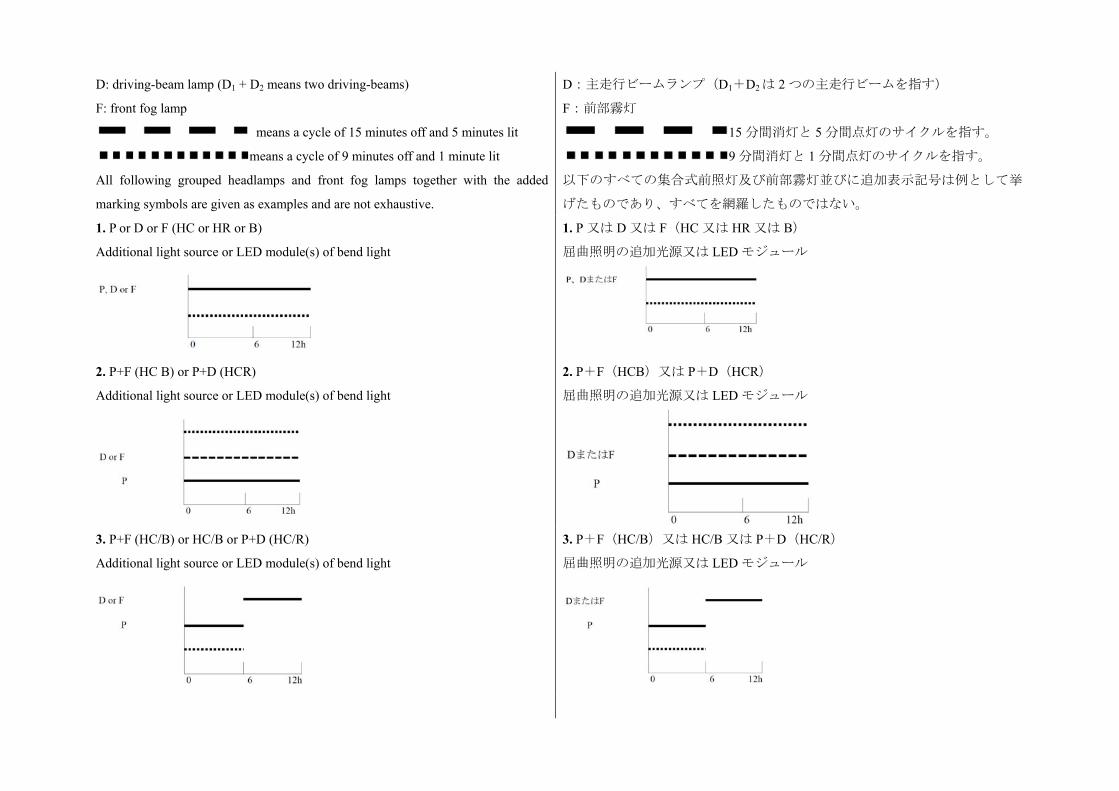
D: driving-beam lamp (D1 + D2 means two driving-beams)
F: front fog lamp
means a cycle of 15 minutes off and 5 minutes lit
means a cycle of 9 minutes off and 1 minute lit
All following grouped headlamps and front fog lamps together with the added
marking symbols are given as examples and are not exhaustive.
D:主走行ビームランプ(D1+D2は 2 つの主走行ビームを指す)
F:前部霧灯
15 分間消灯と 5 分間点灯のサイクルを指す。
9 分間消灯と 1 分間点灯のサイクルを指す。
以下のすべての集合式前照灯及び前部霧灯並びに追加表示記号は例として挙
げたものであり、すべてを網羅したものではない。
1. P or D or F (HC or HR or B)
Additional light source or LED module(s) of bend light
1. P 又は D 又は F(HC 又は HR 又は B)
屈曲照明の追加光源又は LED モジュール
2. P+F (HC B) or P+D (HCR)
Additional light source or LED module(s) of bend light
2. P+F(HCB)又は P+D(HCR)
屈曲照明の追加光源又は LED モジュール
3. P+F (HC/B) or HC/B or P+D (HC/R)
Additional light source or LED module(s) of bend light
3. P+F(HC/B)又は HC/B 又は P+D(HC/R)
屈曲照明の追加光源又は LED モジュール

Annex 5
Minimum requirements for conformity of production control procedures
附則 5
生産の適合性の管理手順に関する最小要件
1. General 1. 一般要件
1.1. The conformity requirements shall be considered satisfied from a mechanical
and a geometrical standpoint, if the differences do not exceed inevitable
manufacturing deviations within the requirements of this Regulation. This condition
also applies to colour.
1.1. 製品の差異が本規則の要件の範囲で避けられない製造上の偏差を超えな
い場合には、適合性の要件は、機械的及び幾何的見地から適合しているものと
みなす。この条件は色度要件にも適用する。
1.2. With respect to photometric performances, the conformity of mass-produced
headlamps shall not be contested if, when testing photometric performances of any
headlamp chosen at random and equipped with a standard (etalon) filament lamp
and/or LED module(s), as present in the lamp:
1.2. 配光性能については、無作為に抽出した、標準(エタロン)フィラメント
電球及び/又は LED モジュールを装備した前照灯に対し、これらを灯火装置に
装着した状態で配光性能試験を実施したときに、以下に該当すれば、量産前照
灯の適合性に疑義のないものとする。
1.2.1. No measured value deviates unfavourably by more than 20 per cent from the
value prescribed in this Regulation. For values B 50 L (or R)1 and zone III, the
maximum unfavourable deviation may be respectively: 1 Letters in brackets refer to headlamps intended for right-hand traffic.
B 50 L (or R):
170 cd equivalent 20 per cent
255 cd equivalent 30 per cent
Zone III
255 cd equivalent 20 per cent
380 cd equivalent 30 per cent
1.2.1. いかなる測定値も本規則に規定した値との偏差が好ましくない方向に
20%を超えないこと。B50L(又は R)1の値及びゾーン III については、好まし
くない方向への最大の偏差はそれぞれ以下にすることができる。 1括弧内の文字は、右側通行用の前照灯に適用する。
B50L(又は R):
20%相当で 170cd
30%相当で 255cd
ゾーン III
20%相当で 255cd
30%相当で 380cd
1.2.2. Or if 1.2.2. あるいは、
1.2.2.1. For the passing-beam, the values prescribed in this Regulation are met at
HV (with a tolerance of +170 cd) and related to that aiming at least one point within
a circle of 0.35 degrees around points B 50 L (or R) (with a tolerance of 85 cd), 75 R
(or L), 50 V, 25 R, 25 L, and in the entire area of zone IV which is not more than
0.52 degrees above line 25 R and 25 L;
1.2.2.1. すれ違い用ビームについては、本規則に規定した値が HV(公差は
+170cd)において、かつ当該照準に関連して点 B50L(又は R)(公差は 85cd)、
75R(又は L)、50V、25R、25L を中心とする 0.35°の円内で少なくとも 1 点に
おいて、かつ線 25R 及び 25L の上 0.52°を超えないゾーン IV の全域において、
適合していること。
1.2.2.2. And if, for the driving-beam, HV being situated within the isolux 0.75 Imax a
tolerance of +20 per cent for maximum values and -20 per cent for minimum values
is observed for the photometric values at any measuring point specified in paragraph
6.3.2. of this Regulation.
1.2.2.2. 及び、主走行ビームについては、HV が 0.75Imaxの等照度曲線の範囲内
にある時に、本規則 6.3.2 項に規定した、いずれの測定点でも配光測定値が最
大値+20%、最小値-20%の公差で観測されたとき。
1.2.3. If the results of the test described above do not meet the requirements, the
alignment of the headlamp may be changed, provided that the axis of the beam is not
displaced laterally by more than 1 deg. to the right or left.
1.2.3. 上記の試験結果が要件を満たさない場合、ビームの軸を左右に 1°を超え
ない範囲で移動して、前照灯の調整を変更してもよい。
1.2.4. If in the case of a lamp equipped with a replaceable filament light source the
results of the tests described above do not meet the requirements, tests shall be
repeated using another standard (etalon) filament lamp.
1.2.4. 交換式フィラメント光源を装着した灯火装置については、上記の試験結
果が要件を満たさない場合、別の標準(エタロン)フィラメント電球を使って
試験を繰り返すものとする。
1.3. With respect to the verification of the change in vertical position of the cut-off
line under the influence of heat, the following procedure shall be applied:
One of the sampled headlamps shall be tested according to the procedure described
in paragraph 2.1. of Annex 4 after being subjected three consecutive times to the
cycle described in paragraph 2.2.2. of Annex 4.
The headlamp shall be considered as acceptable if delta r does not exceed 1.5 mrad.
If this value exceeds 1.5 mrad but is not more than 2.0 mrad, a second sample shall
be subjected to the test after which the mean of the absolute values recorded on both
samples shall not exceed 1.5 mrad.
1.3. 熱の影響によるカットオフラインの垂直位置の変化の確認については、次
の手順を適用するものとする。
供試品として抽出した前照灯の 1 つに、附則 4 の 2.2.2 項に記したサイクルを
3 回連続実施した後、附則 4 の 2.1 項に記した手順に従って試験するものとす
る。
前照灯は、Δr が 1.5mrad を超えない場合、合格とみなすものとする。
この値が 1.5mrad を超えても 2.0mrad 以下の場合は、第二の供試
品を試験するものとする。両方の供試品で記録された絶対値の平
均が 1.5mrad を超えないものとする。
1.4. If, however, vertical adjustment cannot be performed repeatedly to the required
position within the tolerances described in paragraph 6.2.2.3. of this Regulation, one
sample shall be tested according to the procedure described in paragraphs 2. and 3.
of Annex 9.
1.4. ただし、必要な位置への垂直調節を本規則の 6.2.2.3 項に記載した公差の
範囲内で繰り返し実施することができない場合には、1 個の供試品に対し、附
則 9 の 2 項及び 3 項に記載する手順に従って試験を実施するものとする。
2. Minimum requirements for verification of conformity by the manufacturer
For each type of headlamp the holder of the approval mark shall carry out at least
the following tests, at appropriate intervals. The tests shall be carried out in
accordance with the provision of this Regulation.
2. メーカーによる適合性確認のための最小要件
前照灯の各型式について、認可マークの保有者は、少なくとも以下の試験を適
切な間隔で実施しなければならない。試験は本規則の規定に従って行なうもの
とする。
If any sampling shows non-conformity with regard to the type of test concerned,
further samples shall be taken and tested. The manufacturer shall take steps to
ensure the conformity of the production concerned.
当該型式の試験で供試品に不適合が発見された場合、別の供試品を選んで試験
を行なうものとする。メーカーは、当該生産の適合性を保証するための手段を
講じなければならない。
2.1. Nature of tests
Tests of conformity in this Regulation shall cover the photometric characteristics and
the verification of the change in vertical position of the cut-off line under the
influence of heat.
2.1. 試験内容
本規則の適合性試験には、配光特性及び熱の影響を受けたカットオフラインの
垂直位置の変化の確認を含むものとする。
2.2. Methods used in tests 2.2. 試験方法
2.2.1. Tests shall generally be carried out in accordance with the methods set out in
this Regulation.
2.2.1. 試験は通常、本規則に定められた方法に従って実施するものとする。
2.2.2. In any test of conformity carried out by the manufacturer, equivalent methods
may be used with the consent of the competent Authority responsible for approval
tests. The manufacturer is responsible for proving that the applied methods are
equivalent to those laid down in this Regulation.
2.2.2. メーカーの実施する適合性試験では、認可試験を担当する所管官庁の同
意を受けた上で、同等の方法を用いることができる。メーカーは、実施する方
法が本規則に定められた方法と同等であることを証明する責任を負う。
2.2.3. The application of paragraphs 2.2.1. and 2.2.2. requires regular calibration of
test apparatus and its correlation with measurement made by a competent Authority.
2.2.3. 2.2.1 項及び 2.2.2 項を適用する場合、定期的に試験機器に較正を施し、
所管官庁の行なう測定値と比較を行なうことが義務付けられる。
2.2.4. In all cases the reference methods shall be those of this Regulation, particular
for the purpose of administrative verification and sampling.
2.2.4. いずれの場合にも、特に行政官庁が確認と抜取検査を行うためには、本
規則の方法を基準方法とする。
2.3. Nature of sampling
Samples of headlamps shall be selected at random from the production of a uniform
batch. A uniform batch means a set of headlamps of the same type, defined
according to the production methods of the manufacturer.
The assessment shall, in general, cover series production from individual factories.
However, a manufacturer may group together records concerning the same type
from several factories provided these operate under the same quality system and
quality management.
2.3. 抜取検査の性質
前照灯の供試品は、同一バッチの製品から無作為に選択するものとする。同一
バッチとは、メーカーの生産方法によって定められる同一型式の前照灯の集合
をいう。
評価は一般に個々の工場の量産品を対象とするものとする。ただし、複数の工
場が同一の品質システム及び品質管理によって運営されている場合、メーカー
はこれらの工場における同一型式に関する記録を 1 つにまとめることができ
る。
2.4. Measured and recorded photometric characteristics
The sampled headlamps shall be subjected to photometric measurements at the
points provided for in the Regulation, the reading being limited at the points Imax,
HV2, HL, HR3 in the case of a driving-beam, and to points B 50 L (or R), HV, 50 V,
75 R (or L) and 25 L (or R) in the case of the passing-beam (see figure in Annex 3). 2 When the driving-beam is reciprocally incorporated with the passing-beam, HV in
the case of the driving-beam shall be the same measuring point as in the case of the
passing-beam. 3 HL and HR: points "hh" located at 2.5 degrees to the left and to the right of point
HV respectively.
2.4. 配光特性の測定と記録
供試品とする前照灯について、本規則に定める各点で配光測定を行うものとす
る。読み値は、主走行ビームの場合には点 Imax、HV2、HL、HR3、すれ違い用
ビームの場合には点 B50L(又は R)、HV、50V、75R(又は L)及び 25L(又
は R)に限る(附則 3 の図参照)。 2 主走行ビームがすれ違い用ビームと兼用式になっている場合、主走行ビー
ムにおける HV は、すれ違い用ビームにおける測定点と同一にしなければなら
ない。 3HL と HR:点 HV の左右それぞれ 2.5°に位置する「hh」上の点。
2.5. Criteria governing acceptability
The manufacturer is responsible for carrying out a statistical study of the test results
and for defining, in agreement with the Competent Authority, criteria governing
acceptability of his products in order to meet the specification laid down for
verification of conformity of products in paragraph 10.1. of this Regulation.
The criteria governing acceptability shall be such that, with a confidence level of 95
per cent, the minimum probability of passing a spot check in accordance with Annex
7 (first sampling) would be 0.95.
2.5. 合格基準
メーカーは、本規則 10.1 項で製品適合性を確認するために定めた仕様を満た
すために、試験結果の統計的分析を実施し、所管官庁との同意の上で製品の合
格基準を定める責任を負う。
合格基準は、信頼度が 95%で、附則 7 に基づく抜取検査(初回抜取検査)の
最低合格率が 0.95 にならなければならない。
Annex 6
Requirements for lamps incorporating lenses of plastic material - Testing of
lens or material samples and of complete lamps
附則 6
プラスチック材料のレンズを組み込んだ灯火装置の要件-レンズ又は供試材
料及び完成灯火装置の試験
1. General specifications 1. 一般要件
1.1. The samples supplied pursuant to paragraph 2.2.4. of this Regulation shall
satisfy the specifications indicated in paragraphs 2.1. to 2.5. below.
1.1. 本規則 2.2.4 項に基づいて提出した供試品は、下記 2.1 項から 2.5 項に示す
仕様を満たさなければならない。
1.2. The two samples of complete lamps supplied pursuant to paragraph 2.2.3. of
this Regulation and incorporating lenses of plastic material shall, with regard to the
1.2. 本規則 2.2.3 項に基づいて提出した完成灯火装置で、プラスチック材料の
レンズを組み込んでいる供試品 2 個は、レンズの材料に関して、下記 2.6 項に
lens material, satisfy the specifications indicated in paragraph 2.6. below. 示す仕様を満たさなければならない。
1.3. The samples of lenses of plastic material or samples of material shall be
subjected, with the reflector to which they are intended to be fitted (where
applicable), to approval tests in the chronological order indicated in Table A
reproduced in Appendix 1 to this annex.
1.3. プラスチック材料のレンズの供試品又は供試材料は、取り付け対象の反射
器(該当する場合)と共に、本附則の付録 1 に再掲した表 A に示す実施手順
で認可試験を受けなければならない。
1.4. However, if the lamp manufacturer can prove that the product has already
passed the tests prescribed in paragraphs 2.1. to 2.5. below, or the equivalent tests
pursuant to another regulation, those tests need not be repeated; only the tests
prescribed in Appendix 1, Table B, shall be mandatory.
1.4. ただし、当該製品が下記 2.1 項から 2.5 項に定める試験又は他の規則に基
づく同等の試験にすでに合格していることを灯火装置のメーカーが証明でき
る場合には、これらの試験を繰り返す必要はないものとする。付録 1 の表 B
に定める試験のみを必須とする。
2. Tests 2. 試験
2.1. Resistance to temperature changes 2.1. 耐温度変化
2.1.1. Tests
Three new samples (lenses) shall be subjected to five cycles of temperature and
humidity (RH = relative humidity) change in accordance with the following
programme:
3 hours at 40 deg. C +/- 2 deg. C and 85-95 per cent RH;
1 hour at 23 deg. C +/- 5 deg. C and 60-75 per cent RH;
15 hours at -30 deg. C +/- 2 deg. C;
1 hour at 23 deg. C +/- 5 deg. C and 60-75 per cent RH;
3 hours at 80 deg. C +/- 2 deg. C;
1 hour at 23 deg. C +/- 5 deg. C and 60-75 per cent RH;
Before this test, the samples shall be kept at 23 deg. C +/- 5 deg. C and 60-75 per
cent RH for at least four hours.
Note: The periods of one hour at 23 deg. C +/- 5 deg. C shall include the periods of
transition from one temperature to another which are needed in order to avoid
thermal shock effects.
2.1.1. 試験
3 枚の新しい供試品(レンズ)に、下記の手順に従って 5 回のサイクルの温度
及び湿度(RH=相対湿度)の変化を繰り返すものとする。
40℃±2℃、RH85 から 95%で 3 時間
23℃±5℃、RH60 から 75%で 1 時間
-30℃±2℃で 15 時間
23℃±5℃、RH60 から 75%で 1 時間
80℃±2℃で 3 時間
23℃±5℃、RH60 から 75%で 1 時間
この試験の前に、供試品は少なくとも 4 時間、23℃±5℃、RH60 から 75%に
保つものとする。
注:23℃±5℃での 1 時間には、熱衝撃の影響を避けるために必要な 1 つの温
度から他の温度への移行期間を含むものとする。
2.1.2. Photometric measurements 2.1.2. 配光測定
2.1.2.1. Method
Photometric measurements shall be carried out on the samples before and after the
test.
These measurements shall be made using a standard (etalon) lamp and/or LED
module(s), as present in the headlamp, at the following points:
B 50 L and 50 R for the passing-beam (B 50 R and 50 L in the case of headlamps
intended for left-hand traffic);
Imax for the driving-beam.
2.1.2.1. 方法
試験の前後に供試品について配光測定を行わなければならない。
これらの測定は、前照灯に装着した状態の標準(エタロン)の灯火装置及び/
又は LED モジュールを使って、下記の各点で行うものとする。
すれ違い用ビームの場合は B50L と 50R(左側通行用前照灯の場合には B50R
と 50L)
主走行ビームの場合は Imax
2.1.2.2. Results
The variation between the photometric values measured on each sample before and
after the test shall not exceed 10 per cent including the tolerances of the photometric
procedure.
2.1.2.2. 結果
試験前後の各供試品の配光測定値の差は、測光手順の公差を含めて 10%を超
えないものとする。
2.2. Resistance to atmospheric and chemical agents 2.2. 耐候性及び耐化学薬品性
2.2.1. Resistance to atmospheric agents
Three new samples (lenses or samples of material) shall be exposed to radiation
from a source having a spectral energy distribution similar to that of a black body at
a temperature between 5,500 K and 6,000 K. Appropriate filters shall be placed
between the source and the samples so as to reduce as far as possible radiations with
wave lengths smaller than 295 nm and greater than 2,500 nm. The samples shall be
exposed to an energetic illumination of 1,200 W/m2 +/- 200 W/m2 for a period such
that the luminous energy that they receive is equal to 4,500 MJ/m2 +/- 200 MJ/m2.
Within the enclosure, the temperature measured on the black panel placed on a level
with the samples shall be 50 deg. C +/- 5 deg. C. In order to ensure a regular
exposure, the samples shall revolve around the source of radiation at a speed
between 1 and 5 1/min.
The samples shall be sprayed with distilled water of conductivity lower than 1 mS/m
at a temperature of 23 deg. C +/- 5 deg. C, in accordance with the following cycle:
2.2.1. 耐候性
3 個の新しい供試品(レンズ又は供試材料)に、温度 5,500K から 6,000K の黒
体と同じ分光エネルギー分布をもつ光源からの放射に曝すものとする。光源と
供試品の間に適当なフィルターを置いて、295nm 未満の波長と 2,500nm 超の波
長の放射をできるだけ少なくするものとする。供試品に 1,200W/m2±200W/m2
のエネルギー照射を、受容する光量が 4,500MJ/m2±200MJ/m2に等しくなるだ
けの期間、加えるものとする。エンクロージャ内では、供試品と同じレベルに
置いた黒パネル上の測定温度が 50℃±5℃になるものとする。定常的な暴露を
確保するために、供試品を放射源のまわりで 1 から 5 1/min の速度で回転させ
るものとする。
供試品には、下記のサイクルで、温度 23℃±5℃、伝導率 1 mS/m 未満の蒸溜
水を噴霧するものとする。
噴霧:5 分間、乾燥:25 分間。
spraying: 5 minutes; drying: 25 minutes.
2.2.2. Resistance to chemical agents
After the test described in paragraph 2.2.1. above and the measurement described in
paragraph 2.2.3.1. below have been carried out, the outer face of the said three
samples shall be treated as described in paragraph 2.2.2.2. with the mixture defined
in paragraph 2.2.2.1. below.
2.2.2. 耐化学薬品性
上記 2.2.1 項の試験と下記 2.2.3.1 項の測定を行った後、3 個の当該供試品の外
面を下記 2.2.2.1 項に定義した混合物で、2.2.2.2 項に記すように処理するもの
とする。
2.2.2.1. Test mixture
The test mixture shall be composed of 61.5 per cent n-heptane, 12.5 per cent
toluene, 7.5 per cent ethyl tetrachloride, 12.5 per cent trichloroethylene and 6 per
cent xylene (volume per cent).
2.2.2.1. 試験混合物
試験混合物の組成は、n-ヘプタン 61.5%、トルエン 12.5%、四塩化エチル 7.5%、
トリクロロエチレン 12.5%、キシレン 6%(体積%)とする。
2.2.2.2. Application of the test mixture
Soak a piece of cotton cloth (as per ISO 105) until saturation with the mixture
defined in paragraph 2.2.2.1. above and, within 10 seconds, apply it for 10 minutes
to the outer face of the sample at a pressure of 50 N/cm2, corresponding to an effort
of 100 N applied on a test surface of 14 x 14 mm.
During this 10-minute period, the cloth pad shall be soaked again with the mixture
so that the composition of the liquid applied is continuously identical with that of the
test mixture prescribed.
During the period of application, it is permissible to compensate the pressure applied
to the sample in order to prevent it from causing cracks.
2.2.2.2. 試験混合物の塗布
綿布(ISO105 による)を上記 2.2.2.1 項に定義した混合物に飽和するまで浸し、
10 秒以内に、14×14mm の試験表面に加える 100N の力に相当する 50N/cm2の
圧力で、供試品の外側表面に 10 分間それを押し当てる。
この 10 分間の間に綿布を再度混合物に浸し、塗布する液体の組成が所定の試
験混合物と常に同一であるようにする。
ひび割れが生じるのを防ぐため、塗布期間中に供試品に加える圧力を補正でき
るものとする。
2.2.2.3. Cleaning
At the end of the application of the test mixture, the samples shall be dried in the
open air and then washed with the solution described in paragraph 2.3.1.
(Resistance to detergents)
23 deg. C +/- 5 deg. C.
Afterwards the samples shall be carefully rinsed with distilled water containing not
more than 0.2 per cent impurities at 23 deg. C +/- 5 deg. C and then wiped off with a
2.2.2.3. 洗浄
試験混合物の塗布が終了したら、供試品を屋外で乾かし、次に、2.3.1 項(耐
洗剤性)に記す 23℃±5℃の溶液で洗浄するものとする。
その後、含有不純物 0.2%以下の 23℃±5℃の蒸溜水で供試品を丹念にすすぎ、
柔らかい布で拭うものとする。
soft cloth.
2.2.3. Results 2.2.3. 結果
2.2.3.1.
After the test of resistance to atmospheric agents, the outer face of the samples shall
be free from cracks, scratches, chipping and deformation, and the mean
variation in transmission , measured on the three samples according to
the procedure described in Appendix 2 to this annex shall not exceed 0.020 (delta
tm< 0.020).
2.2.3.1. 耐候性試験の後、供試品の外面には、ひび割れ、擦り傷、欠け、変形
がないものとし、本附則の付録2に記す手順に従って3個の供試品で測定した透
過率の変動の平均値 が0.020を超えない(Δtm≦0.020)ものとする。
2.2.3.2.
After the test of resistance to chemical agents, the samples shall not bear any traces
of chemical staining likely to cause a variation of flux diffusion, whose mean
variation , measured on the three samples according to the procedure
described in Appendix 2 to this annex shall not exceed 0.020 (delta dm< 0.020).
2.2.3.2. 耐化学薬品性試験の後、光束拡散の変化を引き起こす恐れのある化学
的汚染のあとが供試品にはみられないものとし、本附則の付録 2 に記す手順に
基づいて、3個の供試品で測定した光束拡散の変動の平均値 が0.020
を超えないものとする。(Δdm≦0.020)
2.2.4. Resistance to light source radiations
The following test shall be done:
Flat samples of each light transmitting plastic component of the headlamp are
exposed to the light of the LED module(s). The parameters such as angles and
distances of these samples shall be the same as in the headlamp. These samples shall
have the same colour and surface treatment, if any, as the parts of the headlamp.
After 1,500 hours of continuous operation, the colorimetric specifications of the
transmitted light must be met, and the surfaces of the samples shall be free of cracks,
scratches, scalings or deformation.
2.2.4. 耐光源放射
以下の試験を行うものとする。
前照灯の各プラスチック製透光部品の平らな供試品を LED モジュールの光に
曝露する。これらの供試品の角度や距離などのパラメータは、前照灯に装着し
た状態と同じにしなければならない。これらの供試品は、前照灯部品と同じ色
及び表面処理(該当する場合)を有するものとする。
1,500 時間の連続点灯の後、透過光の比色分析に関する仕様を満たさなければ
ならず、供試品の表面には、ひび割れ、すり傷、剥がれ又は変形がないものと
する。
2.3. Resistance to detergents and hydrocarbons 2.3. 耐洗剤性及び耐炭化水素性
2.3.1. Resistance to detergents
The outer face of three samples (lenses or samples of material) shall be heated to 50
2.3.1. 耐洗剤性
3 個の供試品(レンズ又は供試材料)の外面を 50℃±5℃まで加熱し、含有不

deg. C +/- 5 deg. C and then immersed for five minutes in a mixture maintained at
23 deg. C +/- 5 deg. C and composed of 99 parts distilled water containing not more
than 0.02 per cent impurities and one part alkylaryl sulphonate.
At the end of the test, the samples shall be dried at 50 deg. C +/- 5 deg. C. The
surface of the samples shall be cleaned with a moist cloth.
純物 0.02%以下の蒸溜水 99%とアルキルアリルスルホネート 1%から成る 23℃
±5℃の混合物に、5 分間浸す。
試験終了後、50℃±5℃で供試品を乾かすものとする。湿った布で供試品の表
面の汚れを取るものとする。
2.3.2. Resistance to hydrocarbons
The outer face of these three samples shall then be lightly rubbed for one minute
with a cotton cloth soaked in a mixture composed of 70 per cent n-heptane and 30
per cent toluene (volume per cent), and shall then be dried in the open air.
2.3.2. 耐炭化水素性
次に、この 3 個の供試品の外面を、n-ヘプタン 70%とトルエン 30%(体積%)
から成る混合物に浸した綿布で、1 分間軽くこするものとする。それから、戸
外で乾かすものとする。
2.3.3. Results
After the above two tests have been performed successively, the mean value of the
variation in transmission , measured on the three samples according to
The procedure described in Appendix 2 to this annex shall not exceed 0.010 (delta
tm< 0.010).
2.3.3. 結果
上記の 2 種類の試験を続けて実施した後、本附則の付録 2 に記す手順に従って
3 個の供試品で測定した透過率の変動の平均値 が 0.010 を超えない
ものとする。(Δtm≦0.010)
2.4. Resistance to mechanical deterioration 2.4. 耐機械的劣化
2.4.1. Mechanical deterioration method
The outer face of the three new samples (lenses) shall be subjected to the uniform
mechanical deterioration test by the method described in Appendix 3 to this annex.
2.4.1. 機械的劣化方法
3 個の新しい供試品(レンズ)の外面に対して、本附則の付録 3 に記す方法に
よって、同一の機械的劣化試験を行うものとする。
2.4.2. Results
After this test, the variations:
in transmission:
and in diffusion:
shall be measured according to the procedure described in Appendix 2 in the area
specified in paragraph 2.2.4.1.1. of this Regulation. The mean value of the three
2.4.2. 結果
この試験後、本規則 2.2.4.1.1 項に規定した範囲で、付録 2 に記す手順に従って、
透過率の変動:
及び拡散率の変動:
を測定するものとする。3 個の供試品の平均値は次の通りとする。
Δtm≦0.100

samples shall be such that:
delta tm< 0.100;
delta dm< 0.050.
Δdm≦0.050
2.5. Test of adherence of coatings, if any 2.5. コーティングの接着試験(該当する場合)
2.5.1. Preparation of the sample
A surface of 20 mm x 20 mm in area of the coating of a lens shall be cut with a razor
blade or a needle into a grid of squares approximately 2 mm x 2 mm. The pressure
on the blade or needle shall be sufficient to cut at least the coating.
2.5.1. 供試品の準備
レンズのコーティング部分の表面を 20mm×20mm にわたって、カミソリの刃
か針で約 2mm×2mm の正方形の格子状に切るものとする。刃又は針にかける
圧力は、少なくともコーティングを切るのに十分な程度とする。
2.5.2. Description of the test
Use an adhesive tape with a force adhesion of 2 N/(cm of width) +/-20 per cent
measured under the standardized conditions specified in Appendix 4 to this annex.
This adhesive tape, which shall be at least 25 mm wide, shall be pressed for at least
five minutes to the surface prepared as prescribed in paragraph 2.5.1. above.
Then the end of the adhesive tape shall be loaded in such a way that the force of
adhesion to the surface considered is balanced by a force perpendicular to that
surface. At this stage, the tape shall be torn off at a constant speed of 1.5 m/s +/- 0.2
m/s.
2.5.2. 試験の説明
本附則の付録 4 に定める標準的な条件下で測定して 2N/(cm 幅)±20%の接着
力をもつ接着テープを使用する。この接着テープを、少なくとも 25mm の幅で、
上記 2.5.1 項に規定した通りに準備した表面に少なくとも 5 分間押しつけるも
のとする。
次に、当該表面への接着力とその表面に対して垂直の力とが均衡を保つよう
に、接着テープの端に負荷をかけるものとする。この段階で、テープは 1.5 m/s
±0.2 m/s の定速でひきちぎれるものとする。
2.5.3. Results
There shall be no appreciable impairment of the gridded area. Impairments at the
intersections between squares or at the edges of the cuts shall be permitted, provided
that the impaired area does not exceed 15 per cent of the gridded surface.
2.5.3. 結果
格子状に切った部分に目に見える損傷がないものとする。正方形の交点や切り
口の端の損傷は、格子状表面の 15%を超えなければ、許容できるものとする。
2.6. Tests of the complete headlamp incorporating a lens of plastic material 2.6. プラスチック材料のレンズを組み込んだ完成後の前照灯の試験
2.6.1. Resistance to mechanical deterioration of the lens surface 2.6.1. レンズ表面の耐機械的劣化
2.6.1.1. Tests
The lens of lamp sample No. 1 shall be subjected to the test described
in paragraph 2.4.1. above.
2.6.1.1. 試験
灯火装置の供試品 No. 1 のレンズに上記 2.4.1 項に記した試験を行うものとす
る。
2.6.1.2. Results 2.6.1.2. 結果

After the test, the results of photometric measurements carried out on the headlamp
in accordance with this Regulation shall not exceed:
(a)By more than 30 per cent the maximum values prescribed at points B 50 L and
HV and by more than 10 per cent below the minimum values prescribed at
point 75 R (in the case of headlamps intended for left-hand traffic, the points to be
considered are B 50 R, HV and 75 L)
or
(b)By more than 10 per cent below the minimum values prescribed for HV in the
case of a headlamp producing driving beam only.
試験後、本規則に従って当該前照灯について実施される配光測定の結果は、
(a)点 B50L 及び点 HV において、所定の最大値より 30%を超えて上回らず、点
75R において、所定の最小値より 10%を超えて下回らないものとする(左側通
行用の前照灯の場合には、該当する点は B50R、HV 及び 75L となる)。
又は
(b)主走行ビームのみを発する前照灯の場合は、HV において所定の最小値より
10%を超えて下回らないものとする。
2.6.2. Test of adherence of coatings, if any
The lens of lamp sample No. 2 shall be subjected to the test described in paragraph
2.5. above.
2.6.2. コーティングの接着試験、該当する場合
灯火装置の供試品No. 2のレンズに上記2.5項に記した試験を行うものとする。
3. Verification of the conformity of production 3. 生産の適合性の確認
3.1. With regard to the materials used for the manufacture of lenses, the lamps of a
series shall be recognized as complying with this Regulation if:
3.1. レンズの製造用に使う材料に関して、量産灯火装置が下記の条件を満たす
ならば、本規則に適合しているとみなすものとする。
3.1.1. After the test for resistance to chemical agents and the test for resistance to
detergents and hydrocarbons, the outer face of the samples exhibits no cracks,
chipping or deformation visible to the naked eye (see paras. 2.2.2., 2.3.1. and 2.3.2.
above);
3.1.1. 耐化学薬品性試験及び耐洗剤性と耐炭化水素性試験の後、供試品の外面
に肉眼で確認できるひび割れ、欠け、又は変形がないこと(上記 2.2.2 項、2.3.1
項、2.3.2 項参照)。
3.1.2. fter the test described in paragraph 2.6.1.1. above, the photometric values at
the points of measurement considered in paragraph 2.6.1.2. above are within the
limits prescribed for conformity of production by this Regulation.
3.1.2. 上記 2.6.1.1 項に記した試験後、上記 2.6.1.2 項で考慮した測定点の配光
測定値が、生産の適合性に関して本規則の定める限度内であること。
3.2. If the test results fail to satisfy the requirements, the tests shall be repeated on
another sample of headlamps selected at random.
3.2. 試験結果がこの要件を満たさない場合には、無作為に抽出した別の前照灯
の供試品で試験を繰り返すものとする。
Annex 6 - Appendix 1
Chronological order of approval tests
附則 6-付録 1
認可試験の操作順序
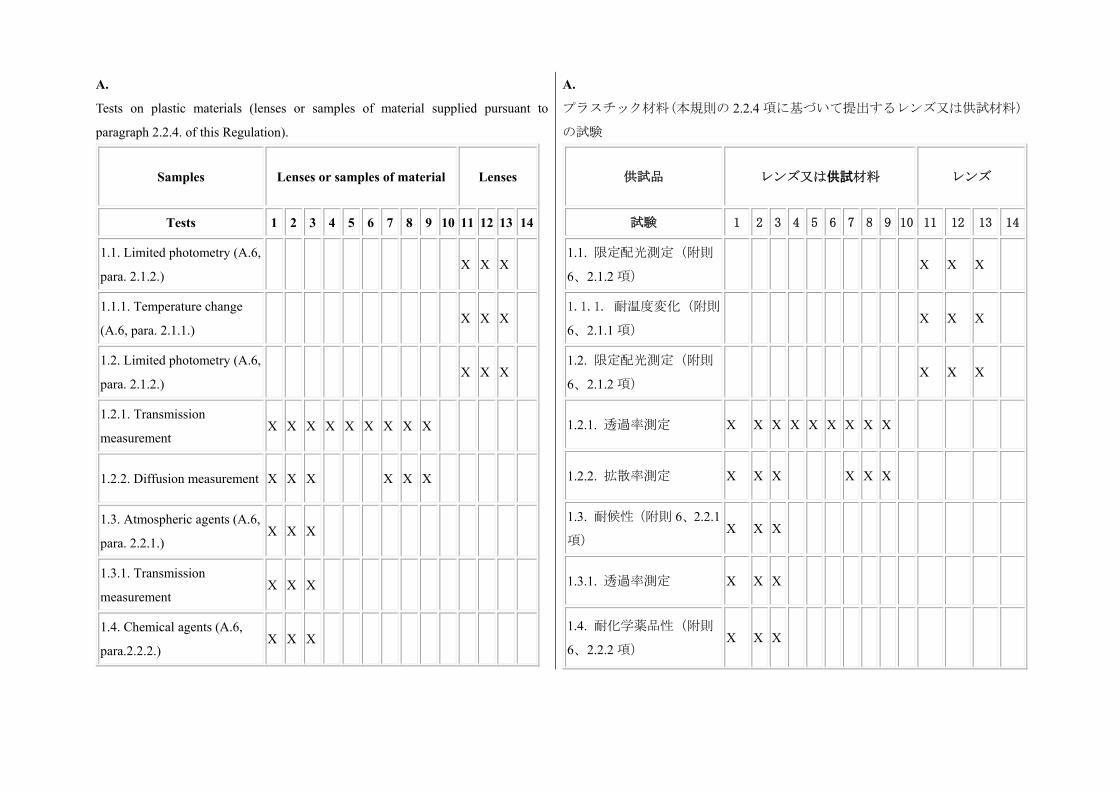
A.
Tests on plastic materials (lenses or samples of material supplied pursuant to
paragraph 2.2.4. of this Regulation).
Samples Lenses or samples of material Lenses
Tests 1 2 3 4 5 6 7 8 9 10 11 12 13 14
1.1. Limited photometry (A.6,
para. 2.1.2.) X X X
1.1.1. Temperature change
(A.6, para. 2.1.1.) X X X
1.2. Limited photometry (A.6,
para. 2.1.2.) X X X
1.2.1. Transmission
measurement X X X X X X X X X
1.2.2. Diffusion measurement X X X X X X
1.3. Atmospheric agents (A.6,
para. 2.2.1.) X X X
1.3.1. Transmission
measurement X X X
1.4. Chemical agents (A.6,
para.2.2.2.) X X X
A.
プラスチック材料(本規則の 2.2.4 項に基づいて提出するレンズ又は供試材料)
の試験
供試品 レンズ又は供試材料 レンズ
試験 1 2 3 4 5 6 7 8 9 10 11 12 13 14
1.1. 限定配光測定(附則
6、2.1.2 項) X X X
1.1.1. 耐温度変化(附則
6、2.1.1 項) X X X
1.2. 限定配光測定(附則
6、2.1.2 項) X X X
1.2.1. 透過率測定 X X X X X X X X X
1.2.2. 拡散率測定 X X X X X X
1.3. 耐候性(附則 6、2.2.1
項) X X X
1.3.1. 透過率測定 X X X
1.4. 耐化学薬品性(附則
6、2.2.2 項) X X X
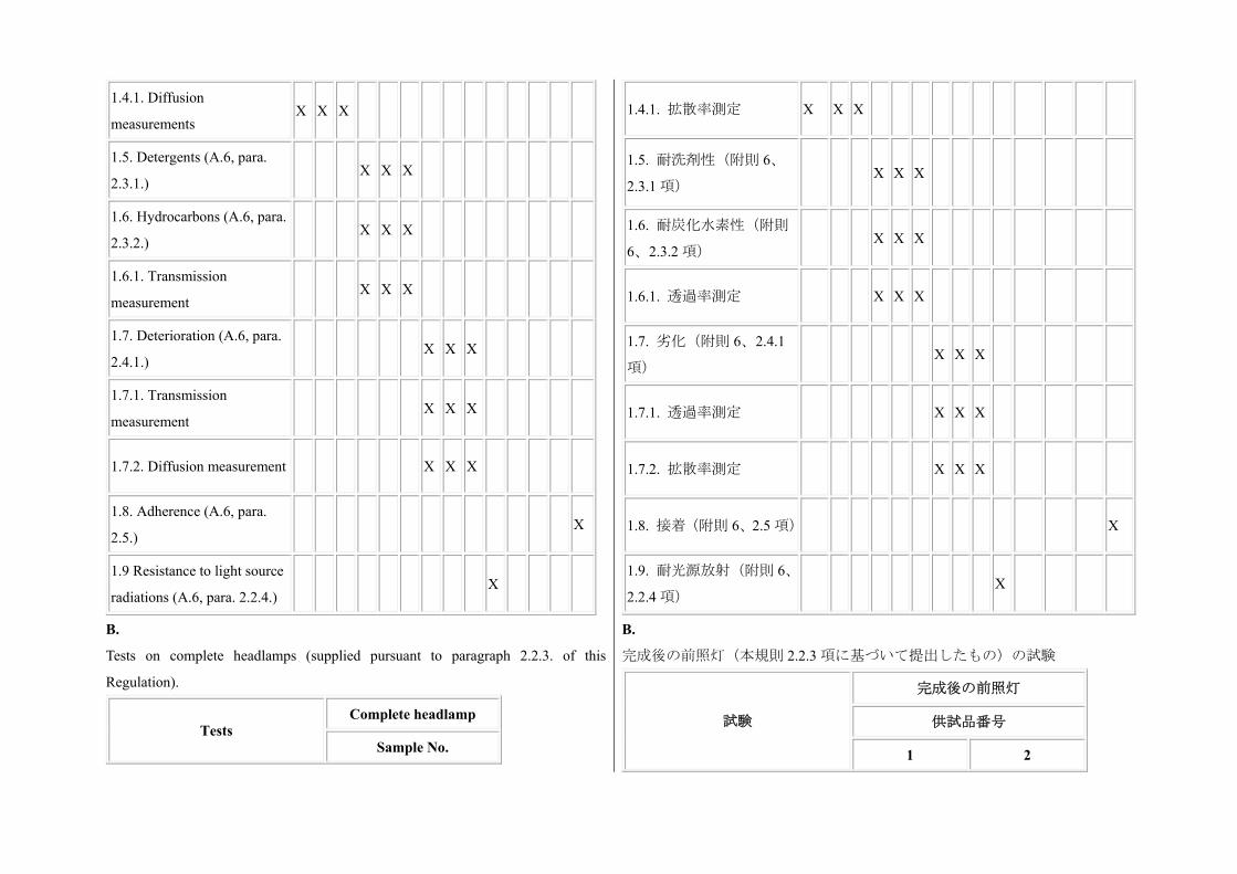
1.4.1. Diffusion
measurements X X X
1.5. Detergents (A.6, para.
2.3.1.) X X X
1.6. Hydrocarbons (A.6, para.
2.3.2.) X X X
1.6.1. Transmission
measurement X X X
1.7. Deterioration (A.6, para.
2.4.1.) X X X
1.7.1. Transmission
measurement X X X
1.7.2. Diffusion measurement X X X
1.8. Adherence (A.6, para.
2.5.) X
1.9 Resistance to light source
radiations (A.6, para. 2.2.4.) X
1.4.1. 拡散率測定 X X X
1.5. 耐洗剤性(附則 6、
2.3.1 項) X X X
1.6. 耐炭化水素性(附則
6、2.3.2 項) X X X
1.6.1. 透過率測定 X X X
1.7. 劣化(附則 6、2.4.1
項) X X X
1.7.1. 透過率測定 X X X
1.7.2. 拡散率測定 X X X
1.8. 接着(附則 6、2.5 項) X
1.9. 耐光源放射(附則 6、
2.2.4 項) X
B.
Tests on complete headlamps (supplied pursuant to paragraph 2.2.3. of this
Regulation).
Tests Complete headlamp
Sample No.
B.
完成後の前照灯(本規則 2.2.3 項に基づいて提出したもの)の試験
試験
完成後の前照灯
供試品番号
1 2
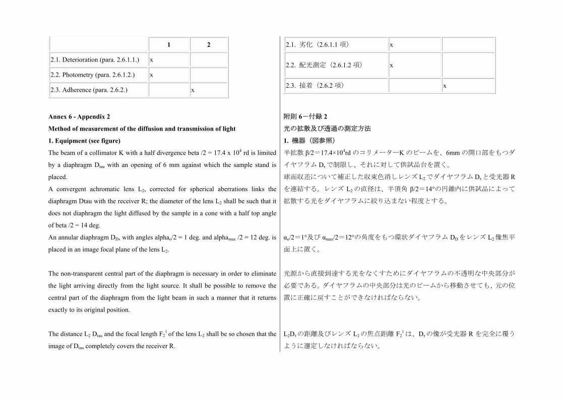
1 2
2.1. Deterioration (para. 2.6.1.1.) x
2.2. Photometry (para. 2.6.1.2.) x
2.3. Adherence (para. 2.6.2.) x
2.1. 劣化(2.6.1.1 項) x
2.2. 配光測定(2.6.1.2 項) x
2.3. 接着(2.6.2 項) x
Annex 6 - Appendix 2
Method of measurement of the diffusion and transmission of light
附則 6-付録 2
光の拡散及び透過の測定方法
1. Equipment (see figure)
The beam of a collimator K with a half divergence beta /2 = 17.4 x 10⁴ rd is limited
by a diaphragm Dtau with an opening of 6 mm against which the sample stand is
placed.
A convergent achromatic lens L2, corrected for spherical aberrations links the
diaphragm Dtau with the receiver R; the diameter of the lens L2 shall be such that it
does not diaphragm the light diffused by the sample in a cone with a half top angle
of beta /2 = 14 deg.
An annular diaphragm DD, with angles alphao/2 = 1 deg. and alphamax /2 = 12 deg. is
placed in an image focal plane of the lens L2.
The non-transparent central part of the diaphragm is necessary in order to eliminate
the light arriving directly from the light source. It shall be possible to remove the
central part of the diaphragm from the light beam in such a manner that it returns
exactly to its original position.
The distance L2 Dtau and the focal length F21 of the lens L2 shall be so chosen that the
image of Dtau completely covers the receiver R.
1. 機器(図参照)
半拡散 β/2=17.4×104rd のコリメーターK のビームを、6mm の開口部をもつダ
イヤフラム Dτで制限し、それに対して供試品台を置く。
球面収差について補正した収束色消しレンズ L2でダイヤフラム Dτと受光器 R
を連結する。レンズ L2 の直径は、半頂角 β/2=14°の円錐内に供試品によって
拡散する光をダイヤフラムに絞り込まない程度とする。
αo/2=1°及び αmax/2=12°の角度をもつ環状ダイヤフラム DDをレンズ L2像焦平
面上に置く。
光源から直接到達する光をなくすためにダイヤフラムの不透明な中央部分が
必要である。ダイヤフラムの中央部分は光のビームから移動させても、元の位
置に正確に戻すことができなければならない。
L2Dτの距離及びレンズ L2の焦点距離 F21は、Dτの像が受光器 R を完全に覆う
ように選定しなければならない。
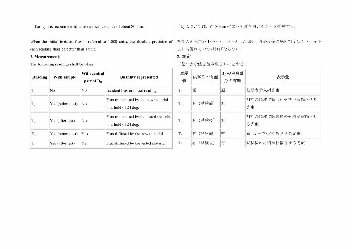
1 For L2 it is recommended to use a focal distance of about 80 mm.
When the initial incident flux is referred to 1,000 units, the absolute precision of
each reading shall be better than 1 unit.
1L2については、約 80mm の焦点距離を用いることを推奨する。
初期入射光束が 1,000 ユニットとした場合、各表示値の絶対精度は 1 ユニット
よりも優れていなければならない。
2. Measurements
The following readings shall be taken:
Reading With sample With central
part of DD Quantity represented
T1 No No Incident flux in initial reading
T2 Yes (before test) No Flux transmitted by the new material
in a field of 24 deg.
T3 Yes (after test) No Flux transmitted by the tested material
in a field of 24 deg.
T4 Yes (before test) Yes Flux diffused by the new material
T5 Yes (after test) Yes Flux diffused by the tested material
2. 測定
下記の表示値を読み取るものとする。
表示
値 供試品の有無
DDの中央部
分の有無表示量
T1 無 無 初期表示入射光束
T2 有(試験前) 無 24℃の領域で新しい材料が透過させる
光束
T3 有(試験後) 無 24℃の領域で試験後の材料が透過させ
る光束
T4 有(試験前) 有 新しい材料が拡散させる光束
T5 有(試験後) 有 試験後の材料が拡散させる光束
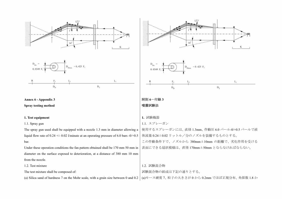
Annex 6 - Appendix 3
Spray testing method
1. Test equipment
附則 6-付録 3
噴霧試験法
1. 試験機器
1.1. Spray gun
The spray gun used shall be equipped with a nozzle 1.3 mm in diameter allowing a
liquid flow rate of 0.24 +/- 0.02 l/minute at an operating pressure of 6.0 bars -0/+0.5
bar.
Under these operation conditions the fan pattern obtained shall be 170 mm 50 mm in
diameter on the surface exposed to deterioration, at a distance of 380 mm 10 mm
from the nozzle.
1.1. スプレーガン
使用するスプレーガンには、直径 1.3mm、作動圧 6.0 バール-0/+0.5 バールで液
体流量 0.24±0.02 リットル/分のノズルを装備するものとする。
この作動条件下で、ノズルから 380mm±10mm の距離で、劣化作用を受ける
表面にできる扇状模様は、直径 170mm±50mm とならなければならない。
1.2. Test mixture
The test mixture shall be composed of:
(a) Silica sand of hardness 7 on the Mohr scale, with a grain size between 0 and 0.2
1.2. 試験混合物
試験混合物の組成は下記の通りとする。
(a)モース硬度 7、粒子の大きさが 0 から 0.2mm でほぼ正規分布、角係数 1.8 か
mm and an almost normal distribution, with an angular factor of 1.8 to 2;
(b) Water of hardness not exceeding 205 g/m3 for a mixture comprising 25 g of sand
per litre of water.
ら 2 の珪砂。
(b)水 1 リットルあたり砂 25g の混合物の場合に硬度が 205g/m3 を超えない水。
2. Test
The outer surface of the lamp lenses shall be subjected once or more than once to the
action of the sand jet produced as described above. The jet shall be sprayed almost
perpendicular to the surface to be tested.
The deterioration shall be checked by means of one or more samples of glass placed
as a reference near the lenses to be tested. The mixture shall be sprayed until the
variation in the diffusion of light on the sample or samples measured by the method
described in Appendix 2, is such that:
Several reference samples may be used to check that the whole surface to be tested
has deteriorated homogeneously.
2. 試験
灯火装置のレンズの外面に一回以上、上記の通りに混合した砂を噴射するもの
とする。この噴射は試験すべき表面に対してほぼ直角に噴霧しなければならな
い。
1 枚以上のガラスの供試品を試験すべきレンズの近くに基準として置き、それ
によって劣化を確認するものとする。付録 2 に記した方法で測定する供試品上
の光の拡散の変動が下記の通りになるまで、混合物を噴霧ものとする。
複数の基準供試品を使って、試験すべき表面全体が均質に劣化したかどうかを
確認することができるものとする。。
Annex 6 - Appendix 4
Adhesive tape adherence test
附則 6-付録 4
接着テープによる接着試験
1. Purpose
This method allows to determine under standard conditions the linear force of
adhesion of an adhesive tape to a glass plate.
1. 目的
この方法により、ガラス板に対する接着テープの線形接着力を標準的な条件の
下で測定することを可能とする。
2. Principle
Measurement of the force necessary to unstick an adhesive tape from a glass plate at
an angle of 90 deg.
2. 原理
接着テープを 90°の角度でガラス板から剥がすのに必要な力を測定する。
3. Specified atmospheric conditions
The ambient conditions shall be at 23 deg. C +/- 5 deg. C and 65 +/- 15 per cent RH.
3. 指定大気条件
周囲の条件は、23℃±5℃、相対湿度(RH)65±15%とする。
4. Test pieces
Before the test, the sample roll of adhesive tape shall be conditioned for 24 hours in
the specified atmosphere (see para. 3 above).
Five test pieces each 400 mm long shall be tested from each roll. These test pieces
shall be taken from the roll after the first three turns were discarded.
4. 試験片
試験前に、接着テープの供試ロールに 24 時間、所定の大気条件(上記 3 項参
照)でコンディショニングを施すものとする。
各ロールからそれぞれ 400mm の試験片 5 片を試験するものとする。これらの
試験片は、最初の 3 巻分を捨てた後、ロールから取るものとする。
5. Procedure
The test shall be under the ambient conditions specified in paragraph 3.
Take the five test pieces while unrolling the tape radially at a speed of approximately
300 mm/s, then apply them within 15 seconds in the following manner:
Apply the tape to the glass plate progressively with a slight length-wise rubbing
movement of the finger, without excessive pressure, in such a manner as to leave no
air bubble between the tape and the glass plate.
Leave the assembly in the specified atmospheric conditions for 10 minutes.
Unstick about 25 mm of the test piece from the plate in a plane perpendicular to the
axis of the test piece.
Fix the plate and fold back the free end of the tape at 90 deg. Apply force in such a
manner that the separation line between the tape and the plate is perpendicular to
this force and perpendicular to the plate.
Pull to unstick at a speed of 300 mm/s +/- 30 mm/s and record the force required.
5. 手順
試験は 3 項に規定した周囲条件の下で、行うものとする。
5 つの試験片をおよそ 300mm/s の速度で半径方向にロールからはがし、15 秒
以内にそれを下記のように貼り付ける。
テープをガラス板に少しずつ、過度の圧力を加えずに、指で縦方向に軽くこす
りつけて、テープとガラス板の間に気泡が残らないように貼り付ける。
このアッセンブリを所定の大気条件下に 10 分間放置する。
ガラス板から試験片の 25mm ほどを試験片の軸に垂直の平面に剥がす。
ガラス板を固定し、テープの固定していない端を 90°に折り返す。テープとガ
ラス板の間の分離線が加える力に対して垂直になり、かつガラス板に対しても
垂直になるように、力を加える。
300mm/s±30mm/s の速度で引き剥がし、要した力を記録する。
6. Results
The five values obtained shall be arranged in order and the median value taken as a
result of the measurement. This value shall be expressed in Newtons per centimetre
of width of the tape.
6. 結果
得られた 5 つの値を順番に並べ、中央値を測定結果とする。この値はテープの
幅 1cm 当たりのニュートンで表すものとする。
Annex 7
Minimum requirements for sampling by an inspector
附則 7
検査官による抜取検査の最小要件
1. General 1. 一般要件

1.1. The conformity requirements shall be considered satisfied from a mechanical
and a geometrical standpoint in accordance with the requirements of this Regulation,
if any, if the differences do not exceed inevitable manufacturing deviations. This
condition also applies to colour.
1.1. 差異が製造上不可避な偏差を超えない場合に、本規則の要件が適用される
場合にはそれに基づいて、適合性の要件を機械的及び幾何学的見地から満たし
ているとみなすものとする。
この条件は色度要件にも適用する。
1.2. With respect to photometric performances, the conformity of mass-produced
headlamps shall not be contested if, when testing photometric performances of any
headlamp chosen at random and equipped with a standard filament lamp and/or LED
module(s) present in the headlamp:
1.2. 配光性能については、無作為に抽出した標準フィラメント電球及び/又は
LED モジュールを装備した前照灯に対し、これらを前照灯に装着した状態で、
配光性能試験を実施したときに以下に該当すれば、量産前照灯の適合性に疑義
のないものとする。
1.2.1. No measured value deviates unfavourably by more than 20 per cent from the
value prescribed in this Regulation. For values B 50 L (or R)1 and zone III, the
maximum unfavourable deviation may be respectively: 1 Letters in brackets refer to headlamps intended for right-hand traffic.
B 50 L (or R):
170 cd equivalent 20 per cent
255 cd equivalent 30 per cent
Zone III
255 cd equivalent 20 per cent
380 cd equivalent 30 per cent"
1.2.1. いかなる測定値にも、本規則に規定した値から 20%を超える不利な差異
がないこと。B50L(又は R)1 の値及びゾーン III については、最大許容偏差
はそれぞれ以下のようにすることができる。 1括弧内の文字は、右側通行用の前照灯に適用する。
B50L(又は R):
20%相当で 170cd
30%相当で 255cd
ゾーン III
20%相当で 255cd
30%相当で 380cd
1.2.2. Or if 1.2.2. あるいは、
1.2.2.1. For the passing-beam, the values prescribed in this Regulation are met at
HV (with a tolerance of +170 cd) and related to that aiming at least one point of each
area delimited on the measuring screen (at 25 m) by a circle 15 cm in radius around
points B 50 L (or R)1 (with a tolerance of 85 cd), 75 R (or L), 50 V, 25 R, 25 L, and
in the entire area of zone IV which is not more than 22.5 cm above line 25 R and 25
L; 1 Letters in brackets refer to headlamps intended for right-hand traffic.
1.2.2.1. すれ違い用ビームについては、本規則に規定した値が HV(公差は
+170cd)において、かつ当該照準に関連して、測定スクリーン(25m の距離)
上で点 B50L(又は R)1(公差は 85cd)、75R(又は L)、50V、25R、25L を中
心とする半径 15cm の円で区切られる各エリアの少なくとも 1 点において、か
つ線 25R 及び 25L の上 22.5cm を超えないゾーン IV の全域において満たされ
ていること。 1 括弧内の文字は、右側通行用の前照灯に適用する。
1.2.2.2. And if, for the driving-beam, HV being situated within the isolux 0.75 Imax, a 1.2.2.2. 主走行ビームについては、HV が 0.75Imaxの等照度曲線の範囲内にある
tolerance of +20 per cent for maximum values and -20 per cent for minimum values
is observed for the photometric values at any measuring point specified in paragraph
6.3.2. of this Regulation. The reference mark is disregarded.
時に、本規則の 6.3.2 項に定めたいずれの測定点においても、配光測定値が最
大値+20%、最小値-20%の公差で観測されたとき。基準マークは無視する。
1.2.3. If the results of the test described above do not meet the requirements, the
alignment of the headlamp may be changed, provided that the axis of the beam is not
displaced laterally by more than 1 deg. to the right or left.
1.2.3. 上記の試験結果が要件を満たさない場合、ビームの軸を左右に 1°を超え
ない範囲で移動させて、前照灯の調整を変更することができるものとする。
1.2.4. If the results of the tests described above do not meet the requirements, tests
shall be repeated using another standard filament lamp and/or LED module(s)
present in the headlamp.
1.2.4. 上記の試験結果が要件を満たさない場合、前照灯に装着した状態の別の
標準フィラメント電球及び/又は LED モジュールを使って、試験を繰り返すも
のとする。
1.2.5. Headlamps with apparent defects are disregarded. 1.2.5. 明らかな瑕疵のある前照灯は無視する。
1.2.6. The reference mark is disregarded. 1.2.6. 基準マークは無視する。
1.3. If, however, vertical adjustment cannot be performed repeatedly to the required
position within the tolerances described in paragraph 6.2.2.3. of this Regulation, one
sample shall be tested according to the procedure described in paragraphs 2. and 3.
of Annex 9.
1.3. ただし、必要な位置への垂直調節を本規則の 6.2.2.3 項に記載した公差の
範囲内で繰り返し実施することができない場合には、1 個の供試品に対し、附
則 9 の 2 項及び 3 項に記載する手順に従って試験を実施するものとする。
2. First sampling
In the first sampling four headlamps are selected at random. The first sample of two
is marked A, the second sample of two is marked B.
2. 初回抜取検査
初回抜取検査では、4 個の前照灯を無作為に抽出するものとする。最初の供試
品となる 2 個に A と表示し、二回目の供試品となる 2 個に B と表示する。
2.1. The conformity is not contested 2.1. 適合性に疑義のない場合
2.1.1. Following the sampling procedure shown in Figure 1 of this annex the
conformity of mass-produced headlamps shall not be contested if the deviations of
the measured values of the headlamps in the unfavourable directions are:
2.1.1. 本附則の図 1 に示した抜取検査手順後に、当該前照灯の測定値の不利な
方向への偏差が下記に該当する場合には、量産前照灯の適合性に疑義のないも
のとする。
2.1.1.1. Sample A
A1:
one headlamp: 0 per cent
one headlamp: not more than 20 per cent
A2:
2.1.1.1. 供試品 A
A1:
前照灯 1 個:0%
前照灯 1 個:20%以下
A2:
both headlamps: more than 0 per cent
but not more than 20 per cent
go to sample B
前照灯 2 個:0%超
ただし 20%以下
供試品 B に進む。
2.1.1.2. Sample B
B1:
both headlamps: 0 per cent
2.1.1.2. 供試品 B
B1:
前照灯 2 個:0%
2.1.2.
Or if the conditions of paragraph 1.2.2. for sample A are fulfilled.
2.1.2.
又は、供試品 A について 1.2.2 項の条件が満たされるとき。
2.2. The conformity is contested 2.2. 適合性に疑義がある場合
2.2.1. Following the sampling procedure shown in Figure 1 of this annex the
conformity of mass-produced headlamps shall be contested and the manufacturer
requested to make his production meet the requirements (alignment) if the deviations
of the measured values of the headlamps are:
2.2.1. 本附則の図 1 に示した抜取検査手順後に、当該前照灯の測定値の偏差が
下記に該当する場合には、量産前照灯の適合性には疑義があり、製品が(調整)
要件を満たすようにメーカーに要求するものとする。
2.2.1.1. Sample A
A3:
one headlamp: not more than 20 per cent
one headlamp: more than 20 per cent
but not more than 30 per cent
2.2.1.2. Sample B
B2:
in the case of A2
one headlamp: more than 0 per cent
but not more than 20 per cent one headlamp: not more than 20 per cent
B3:
in the case of A2
one headlamp: 0 per cent
2.2.1.1. 供試品 A
A3:
前照灯 1 個:20%以下
前照灯 1 個:20%超
ただし 30%以下
2.2.1.2. 供試品 B
B2:
A2 の場合
前照灯 1 個:0%超
ただし 20%以下
前照灯 1 個:20%以下
B3:
one headlamp: more than 20 per cent
but not more than 30 per cent
A2 の場合
前照灯 1 個:0%
前照灯 1 個:20%超
ただし 30%以下
2.2.2. Or if the conditions of paragraph 1.2.2. for sample A are not fulfilled. 2.2.2. あるいは、供試品 A について 1.2.2 項の条件が満たされないとき。
2.3. Approval withdrawn
Conformity shall be contested and paragraph 11. applied if, following the sampling
procedure shown in Figure 1 of this annex, the deviations of the measured values of
the headlamps are:
2.3.1. Sample A
A4:
one headlamp: not more than 20 per cent
one headlamp: more than 30 per cent
A5:
both headlamps: more than 20 per cent
2.3.2. Sample B
B4:
in the case of A2
one headlamp: more than 0 per cent
but not more than 20 per cent
one headlamp: more than 20 per cent
B5:
in the case of A2
both headlamps: more than 20 per cent
B6:
in the case of A2
2.3. 認可取消
本附則の図 1 の抜取検査手順後に、前照灯の測定値の偏差が下記に該当する場
合、適合性には疑義があり、11 項を適用するものとする。
2.3.1. 供試品 A
A4:
前照灯 1 個:20%以下
前照灯 1 個:30%超
A5:
前照灯 2 個:20%超
2.3.2. 供試品 B
B4:
A2 の場合
前照灯 1 個:0%超
ただし 20%以下
前照灯 1 個:20%超
B5:
A2 の場合
前照灯 2 個:20%超
B6:
A2 の場合
one headlamp: 0 per cent
one headlamp: more than 30 per cent
2.3.3. Or if the conditions of paragraph 1.2.2. for samples A and B are not fulfilled.
前照灯 1 個:0%
前照灯 1 個:30%超
2.3.3. あるいは、供試品 A 及び B について 1.2.2 項の条件が満たされないとき。
3. Repeated sampling
In the case of A3, B2, B3 a repeated sampling, third sample C of two headlamps,
selected from stock manufactured after alignment, is necessary within two months'
time after the notification.
3. 反復抜取検査
A3、B2、B3 の場合、通知後 2 ヵ月以内に、調整後の製造在庫品から三回目の
供試品となる C の前照灯 2 個を選び、反復抜取検査を実施しなければならな
い
3.1. The conformity is not contested 3.1. 適合性に疑義のない場合
3.1.1. Following the sampling procedure shown in Figure 1 of this annex the
conformity of mass-produced headlamps shall not be contested if the deviations of
the measured values of the headlamps are:
3.1.1. 本附則の図 1 に示した抜取検査手順の後に、当該前照灯の測定値の偏差
が下記に該当する場合には、量産前照灯の適合性に疑義がないものとする。
3.1.1.1. Sample C
C1:
one headlamp: 0 per cent
one headlamp: not more than 20 per cent
C2:
both headlamps: more than 0 per cent
but not more than 20 per cent
go to sample D
3.1.1.1. 供試品 C
C1:
前照灯 1 個:0%
前照灯 1 個:20%以下
C2:
前照灯 2 個:0%超
ただし 20%以下
供試品 D に進む。
3.1.1.2. Sample D
D1:
in the case of C2
both headlamps: 0 per cent
3.1.1.2. 供試品 D
D1:
C2 の場合
前照灯 2 個:0%
3.1.2. Or if the conditions of paragraph 1.2.2. for sample C are fulfilled. 3.1.2. 又は、供試品 C について 1.2.2 項の条件が満たされるとき。
3.2. The conformity is contested 3.2. 適合性に疑義がある場合
3.2.1. Following the sampling procedure shown in Figure 1 of this annex the
conformity of mass-produced headlamps shall be contested and the manufacturer
3.2.1. 本附則の図 1 に示した抜取検査手順の後に、当該前照灯の測定値の偏差
が下記に該当する場合には、量産前照灯の適合性には疑義があり、製品が(調
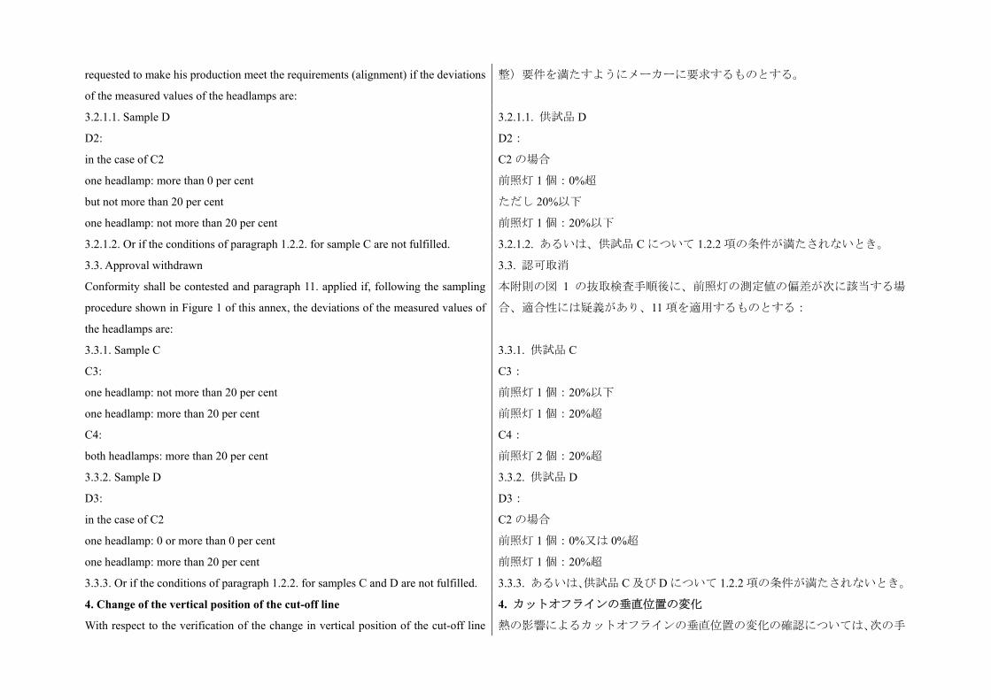
requested to make his production meet the requirements (alignment) if the deviations
of the measured values of the headlamps are:
整)要件を満たすようにメーカーに要求するものとする。
3.2.1.1. Sample D
D2:
in the case of C2
one headlamp: more than 0 per cent
but not more than 20 per cent
one headlamp: not more than 20 per cent
3.2.1.1. 供試品 D
D2:
C2 の場合
前照灯 1 個:0%超
ただし 20%以下
前照灯 1 個:20%以下
3.2.1.2. Or if the conditions of paragraph 1.2.2. for sample C are not fulfilled. 3.2.1.2. あるいは、供試品 C について 1.2.2 項の条件が満たされないとき。
3.3. Approval withdrawn
Conformity shall be contested and paragraph 11. applied if, following the sampling
procedure shown in Figure 1 of this annex, the deviations of the measured values of
the headlamps are:
3.3. 認可取消
本附則の図 1 の抜取検査手順後に、前照灯の測定値の偏差が次に該当する場
合、適合性には疑義があり、11 項を適用するものとする:
3.3.1. Sample C
C3:
one headlamp: not more than 20 per cent
one headlamp: more than 20 per cent
C4:
both headlamps: more than 20 per cent
3.3.1. 供試品 C
C3:
前照灯 1 個:20%以下
前照灯 1 個:20%超
C4:
前照灯 2 個:20%超
3.3.2. Sample D
D3:
in the case of C2
one headlamp: 0 or more than 0 per cent
one headlamp: more than 20 per cent
3.3.2. 供試品 D
D3:
C2 の場合
前照灯 1 個:0%又は 0%超
前照灯 1 個:20%超
3.3.3. Or if the conditions of paragraph 1.2.2. for samples C and D are not fulfilled. 3.3.3. あるいは、供試品 C 及び D について 1.2.2 項の条件が満たされないとき。
4. Change of the vertical position of the cut-off line
With respect to the verification of the change in vertical position of the cut-off line
4. カットオフラインの垂直位置の変化
熱の影響によるカットオフラインの垂直位置の変化の確認については、次の手
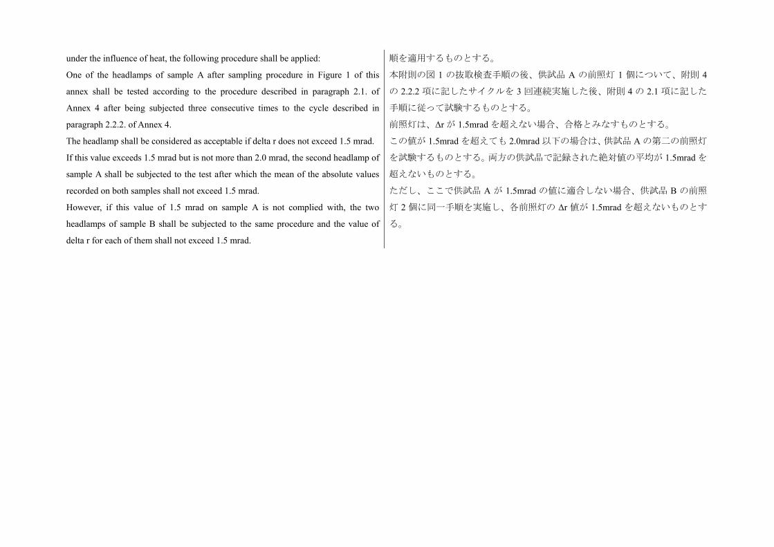
under the influence of heat, the following procedure shall be applied:
One of the headlamps of sample A after sampling procedure in Figure 1 of this
annex shall be tested according to the procedure described in paragraph 2.1. of
Annex 4 after being subjected three consecutive times to the cycle described in
paragraph 2.2.2. of Annex 4.
The headlamp shall be considered as acceptable if delta r does not exceed 1.5 mrad.
If this value exceeds 1.5 mrad but is not more than 2.0 mrad, the second headlamp of
sample A shall be subjected to the test after which the mean of the absolute values
recorded on both samples shall not exceed 1.5 mrad.
However, if this value of 1.5 mrad on sample A is not complied with, the two
headlamps of sample B shall be subjected to the same procedure and the value of
delta r for each of them shall not exceed 1.5 mrad.
順を適用するものとする。
本附則の図 1 の抜取検査手順の後、供試品 A の前照灯 1 個について、附則 4
の 2.2.2 項に記したサイクルを 3 回連続実施した後、附則 4 の 2.1 項に記した
手順に従って試験するものとする。
前照灯は、Δr が 1.5mrad を超えない場合、合格とみなすものとする。
この値が 1.5mrad を超えても 2.0mrad 以下の場合は、供試品 A の第二の前照灯
を試験するものとする。両方の供試品で記録された絶対値の平均が 1.5mrad を
超えないものとする。
ただし、ここで供試品 A が 1.5mrad の値に適合しない場合、供試品 B の前照
灯 2 個に同一手順を実施し、各前照灯の Δr 値が 1.5mrad を超えないものとす
る。
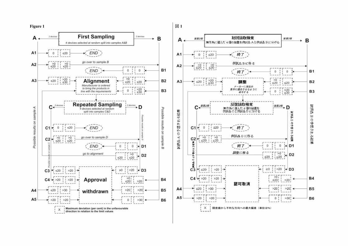
Figure 1
図 1
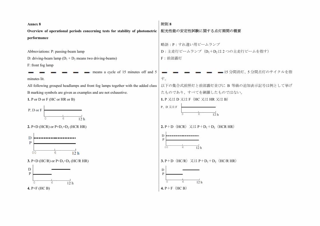
Annex 8
Overview of operational periods concerning tests for stability of photometric
performance
Abbreviations: P: passing-beam lamp
D: driving-beam lamp (D1 + D2 means two driving-beams)
F: front fog lamp
means a cycle of 15 minutes off and 5
minutes lit.
All following grouped headlamps and front fog lamps together with the added class
B marking symbols are given as examples and are not exhaustive.
附則 8
配光性能の安定性試験に関する点灯期間の概要
略語:P:すれ違い用ビームランプ
D:主走行ビームランプ(D1+D2は 2 つの主走行ビームを指す)
F:前部霧灯
15 分間消灯、5 分間点灯のサイクルを指
す。
以下の集合式前照灯と前部霧灯並びに B 等級の追加表示記号は例として挙げ
たものであり、すべてを網羅したものではない。
1. P or D or F (HC or HR or B)
1. P 又は D 又は F(HC 又は HR 又は B)
2. P+D (HCR) or P+D1+D2 (HCR HR)
2. P+D(HCR)又は P+D1+D2(HCR HR)
3. P+D (HC/R) or P+D1+D2 (HC/R HR)
3. P+D(HC/R)又は P+D1+D2(HC/R HR)
4. P+F (HC B) 4. P+F(HC B)
P、D 又は F
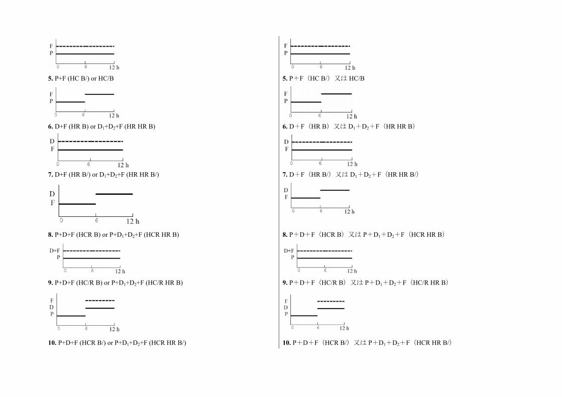
5. P+F (HC B/) or HC/B
5. P+F(HC B/)又は HC/B
6. D+F (HR B) or D1+D2+F (HR HR B)
6. D+F(HR B)又は D1+D2+F(HR HR B)
7. D+F (HR B/) or D1+D2+F (HR HR B/)
7. D+F(HR B/)又は D1+D2+F(HR HR B/)
8. P+D+F (HCR B) or P+D1+D2+F (HCR HR B)
8. P+D+F(HCR B)又は P+D1+D2+F(HCR HR B)
9. P+D+F (HC/R B) or P+D1+D2+F (HC/R HR B)
9. P+D+F(HC/R B)又は P+D1+D2+F(HC/R HR B)
10. P+D+F (HCR B/) or P+D1+D2+F (HCR HR B/) 10. P+D+F(HCR B/)又は P+D1+D2+F(HCR HR B/)

11. P+D+F (HC/R B/) or P+D1+D2+F (HC/R HR B/)
11. P+D+F(HC/R B/)又は P+D1+D2+F(HC/R HR B/)
Annex 9
Instrumental verification of the "cut-off" for passing-beam headlamps
1. General
In the case where paragraph 6.2.2.4. of this Regulation applies, the quality of the
"cut-off" shall be tested according to the requirements set out in paragraph 2. below
and the instrumental vertical and horizontal adjustment of the beam shall be
performed according to the requirements set out in paragraph 3. below.
Before carrying out the measurement of the quality of "cut-off" and the instrumental
aiming procedure, a visual pre-aim in accordance with paragraphs 6.2.2.1. and
6.2.2.2. of this Regulation is required.
附則 9
すれ違い用ビーム前照灯の「カットオフ」に関する計測による検証
1. 一般要件
本規則の 6.2.2.4 項に該当する場合には、下記 2 項に規定する要件に従って「カ
ットオフ」の質を試験するものとし、下記 3 項に規定する要件に従って計測に
よるビームの垂直調節及び水平調節を実施するものとする。
「カットオフ」の質の測定並びに計測による照準手順を実施する前に、本規則
の 6.2.2.1 項及び 6.2.2.2 項に従って目視による予備照準を行う必要がある。
2. Measurement of the quality of the "cut-off"
To determine the minimum sharpness, measurements shall be performed by
vertically scanning through the horizontal part of the "cut-off" in angular steps of
0.05 deg. at either a measurement distance of:
(a) 10 m with a detector having a diameter of approximately 10 mm or
(b) 25 m with a detector having a diameter of approximately 30 mm.
The measuring distance at which the test was carried out shall be recorded in item 9.
2. 「カットオフ」の質の測定
最小鮮明度を決定するには、以下のいずれかの測定距離において、0.05°の角
度間隔で、「カットオフ」の水平部分の値を垂直方向に読み取りながら測定を
行うものとする。
(a)直径約 10mm の検出器を用いて、10m、又は、
(b)直径約 30mm の検出器を用いて、25m。

of the communication form (see Annex 1 of this Regulation).
To determine the maximum sharpness, measurements shall be performed by
vertically scanning through the horizontal part of the "cut-off" in angular steps of
0.05 deg. exclusively at a measurement distance of 25 m and with a detector having
a diameter of approximately 30 mm.
The "cut-off" quality shall be considered acceptable if the requirements of
paragraphs 2.1. to 2.3. below comply with at least one set of measurements.
試験を実施した際の測定距離は、通知書の 9 項(本規則の附則 1 を参照)に記
録するものとする。
最大鮮明度を決定するには、測定距離 25m のみにおいて、直径約 30mm の検
出器のみを用いて、0.05°の角度間隔で、「カットオフ」の水平部分の値を垂直
方向に読み取りながら測定を行うものとする。
「カットオフ」の質は、少なくとも 1 セットの測定が下記 2.1 項から 2.3 項の
要件に適合した場合に合格とみなすものとする。
2.1. Not more than one "cut-off" shall be visible1. 1 This paragraph should be amended when an objective test method is available.
2.1. 目に見える「カットオフ」が 2 つ以上ないものとする 1。 1 この項は、客観的な試験方法が使用できるようになった時に改訂すべきもの
とする。
2.2. Sharpness of "cut-off"
The sharpness factor G is determined by scanning vertically through the horizontal
part of the "cut-off" at 2.5 deg. from the V-V where:
G = (log Ebeta - log E(beta + 0.1 deg.)) where beta = the vertical position in degrees.
The value of G shall not be less than 0.13 (minimum sharpness) and not greater than
0.40 (maximum sharpness).
2.2. 「カットオフ」の鮮明度
V-V から 2.5°のところで「カットオフ」の水平部分の値を垂直方向に読み取る
ことにより、鮮明度の係数 G を求める。ここで:
G = (log Eβ - log E(β + 0.1°))、ここで、β=垂直位置(単位は、°)。
G 値は、0.13 以上(最小鮮明度)、0.40 以下(最大鮮明度)とする。
2.3. Linearity
The part of the horizontal "cut-off" that serves for vertical adjustment shall be
horizontal between 1.5 deg. and 3.5 deg. from the V-V line (see Figure 1).
The inflection points of the "cut-off" gradient at the vertical lines at 1.5 deg., 2.5
deg. and 3.5 deg. shall be determined by the equation:
The maximum vertical distance between the inflection points determined shall not
exceed 0.2 deg.
(d2 (log E) / d beta2 = 0).
2.3. 線形性
垂直調節で使用する「カットオフ」の水平部分は、V-V 線から 1.5°を起点とし
て 3.5°を終点とする範囲において、水平であるものとする(図 1 を参照)。
1.5°、2.5°及び 3.5°における垂直線の「カットオフ」勾配の屈折点は、以下の
方程式により求めるものとする。
求められた屈折点間の最大垂直距離は、0.2°を超えないものとする。
(d2 (log E) / dβ2 = 0)
3. Vertical and horizontal adjustment
If the "cut-off" complies with the quality requirements of paragraph 2. of this annex,
3. 垂直調節及び水平調節
「カットオフ」が本附則、2 項の質に関する要件に適合する場合、計測により
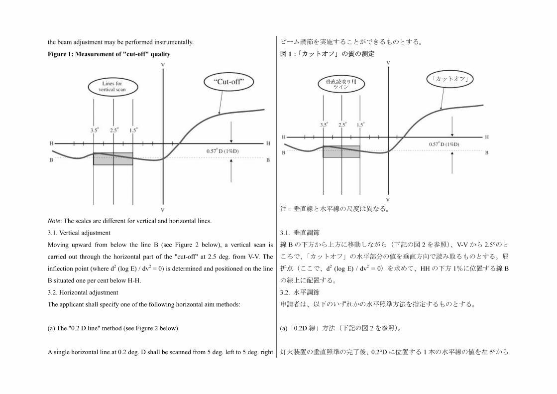
the beam adjustment may be performed instrumentally.
Figure 1: Measurement of "cut-off" quality
Note: The scales are different for vertical and horizontal lines.
ビーム調節を実施することができるものとする。
図 1:「カットオフ」の質の測定
注:垂直線と水平線の尺度は異なる。
3.1. Vertical adjustment
Moving upward from below the line B (see Figure 2 below), a vertical scan is
carried out through the horizontal part of the "cut-off" at 2.5 deg. from V-V. The
inflection point (where d2 (log E) / dv2 = 0) is determined and positioned on the line
B situated one per cent below H-H.
3.1. 垂直調節
線 B の下方から上方に移動しながら(下記の図 2 を参照)、V-V から 2.5°のと
ころで、「カットオフ」の水平部分の値を垂直方向で読み取るものとする。屈
折点(ここで、d2 (log E) / dv2 = 0)を求めて、HH の下方 1%に位置する線 B
の線上に配置する。
3.2. Horizontal adjustment
The applicant shall specify one of the following horizontal aim methods:
(a) The "0.2 D line" method (see Figure 2 below).
A single horizontal line at 0.2 deg. D shall be scanned from 5 deg. left to 5 deg. right
3.2. 水平調節
申請者は、以下のいずれかの水平照準方法を指定するものとする。
(a)「0.2D 線」方法(下記の図 2 を参照)。
灯火装置の垂直照準の完了後、0.2°D に位置する 1 本の水平線の値を左 5°から
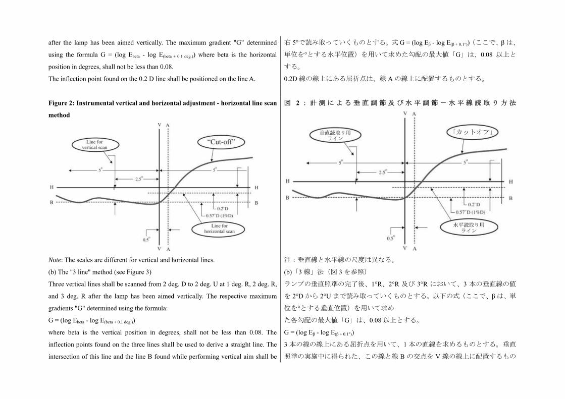
after the lamp has been aimed vertically. The maximum gradient "G" determined
using the formula G = (log Ebeta - log E(beta + 0.1 deg.)) where beta is the horizontal
position in degrees, shall not be less than 0.08.
The inflection point found on the 0.2 D line shall be positioned on the line A.
右 5°で読み取っていくものとする。式 G = (log Eβ - log E(β + 0.1°))(ここで、βは、
単位を°とする水平位置)を用いて求めた勾配の最大値「G」は、0.08 以上と
する。
0.2D 線の線上にある屈折点は、線 A の線上に配置するものとする。
Figure 2: Instrumental vertical and horizontal adjustment - horizontal line scan
method
Note: The scales are different for vertical and horizontal lines.
図 2 : 計 測 に よ る 垂 直 調 節 及 び 水 平 調 節 - 水 平 線 読 取 り 方 法
注:垂直線と水平線の尺度は異なる。
(b) The "3 line" method (see Figure 3)
Three vertical lines shall be scanned from 2 deg. D to 2 deg. U at 1 deg. R, 2 deg. R,
and 3 deg. R after the lamp has been aimed vertically. The respective maximum
gradients "G" determined using the formula:
G = (log Ebeta - log E(beta + 0.1 deg.))
where beta is the vertical position in degrees, shall not be less than 0.08. The
inflection points found on the three lines shall be used to derive a straight line. The
intersection of this line and the line B found while performing vertical aim shall be
(b)「3 線」法(図 3 を参照)
ランプの垂直照準の完了後、1°R、2°R 及び 3°R において、3 本の垂直線の値
を 2°D から 2°U まで読み取っていくものとする。以下の式(ここで、βは、単
位を°とする垂直位置)を用いて求め
た各勾配の最大値「G」は、0.08 以上とする。
G = (log Eβ - log E(β + 0.1°))
3 本の線の線上にある屈折点を用いて、1 本の直線を求めるものとする。垂直
照準の実施中に得られた、この線と線 B の交点を V 線の線上に配置するもの
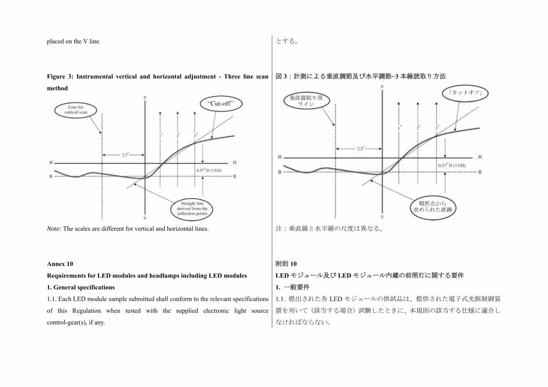
placed on the V line.
とする。
Figure 3: Instrumental vertical and horizontal adjustment - Three line scan
method
Note: The scales are different for vertical and horizontal lines.
図 3:計測による垂直調節及び水平調節−3 本線読取り方法
注:垂直線と水平線の尺度は異なる。
Annex 10
Requirements for LED modules and headlamps including LED modules
附則 10
LED モジュール及び LED モジュール内蔵の前照灯に関する要件
1. General specifications 1. 一般要件
1.1. Each LED module sample submitted shall conform to the relevant specifications
of this Regulation when tested with the supplied electronic light source
control-gear(s), if any.
1.1. 提出された各 LED モジュールの供試品は、提供された電子式光源制御装
置を用いて(該当する場合)試験したときに、本規則の該当する仕様に適合し
なければならない。
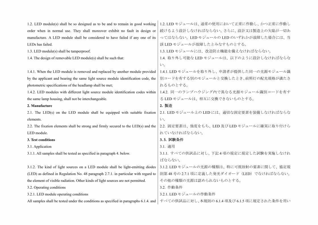
1.2. LED module(s) shall be so designed as to be and to remain in good working
order when in normal use. They shall moreover exhibit no fault in design or
manufacture. A LED module shall be considered to have failed if any one of its
LEDs has failed.
1.2. LED モジュールは、通常の使用において正常に作動し、かつ正常に作動し
続けるよう設計しなければならない。さらに、設計又は製造上の欠陥が一切あ
ってはならない。LED モジュールの LED のいずれかが故障した場合には、当
該 LED モジュールが故障したとみなすものとする。
1.3. LED module(s) shall be tamperproof. 1.3. LED モジュールには、改造防止機能を備えなければならない。
1.4. The design of removable LED module(s) shall be such that: 1.4. 取り外し可能な LED モジュールは、以下のように設計しなければならな
い。
1.4.1. When the LED module is removed and replaced by another module provided
by the applicant and bearing the same light source module identification code, the
photometric specifications of the headlamp shall be met;
1.4.1. LED モジュールを取り外し、申請者が提供した同一の光源モジュール識
別コードを有する別のモジュールと交換したとき、前照灯の配光規格が満たさ
れるものとする。
1.4.2. LED modules with different light source module identification codes within
the same lamp housing, shall not be interchangeable.
1.4.2. 同一のランプハウジング内で異なる光源モジュール識別コードを有す
る LED モジュールは、相互に交換できないものとする。
2. Manufacture
2.1. The LED(s) on the LED module shall be equipped with suitable fixation
elements.
2. 製造
2.1. LED モジュール上の LED には、適切な固定要素を装備しなければならな
い。
2.2. The fixation elements shall be strong and firmly secured to the LED(s) and the
LED module.
2.2. 固定要素は、強度をもち、LED 及び LED モジュールに確実に取り付けら
れていなければならない。
3. Test conditions
3.1. Application
3. 3. 試験条件
3.1. 適用
3.1.1. All samples shall be tested as specified in paragraph 4. below. 3.1.1. すべての供試品に対し、下記 4 項の規定に規定した試験を実施しなけれ
ばならない。
3.1.2. The kind of light sources on a LED module shall be light-emitting diodes
(LED) as defined in Regulation No. 48 paragraph 2.7.1. in particular with regard to
the element of visible radiation. Other kinds of light sources are not permitted.
3.1.2. LED モジュールの光源の種類は、特に可視放射の要素に関して、協定規
則第 48 号の 2.7.1 項に定義した発光ダイオード(LED)でなければならない。
その他の種類の光源は認められないものとする。
3.2. Operating conditions 3.2. 作動条件
3.2.1. LED module operating conditions
All samples shall be tested under the conditions as specified in paragraphs 6.1.4. and
3.2.1. LED モジュールの作動条件
すべての供試品に対し、本規則の 6.1.4 項及び 6.1.5 項に規定された条件を用い
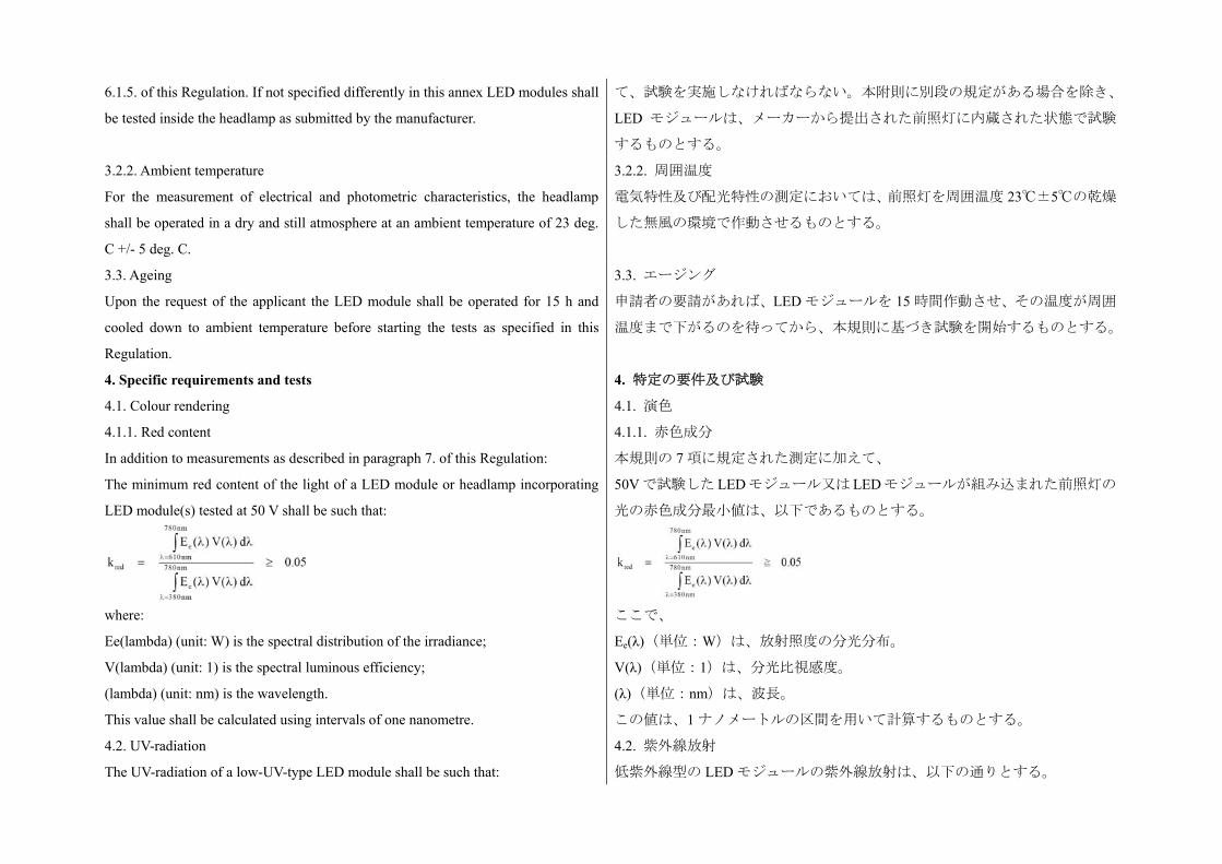
6.1.5. of this Regulation. If not specified differently in this annex LED modules shall
be tested inside the headlamp as submitted by the manufacturer.
て、試験を実施しなければならない。本附則に別段の規定がある場合を除き、
LED モジュールは、メーカーから提出された前照灯に内蔵された状態で試験
するものとする。
3.2.2. Ambient temperature
For the measurement of electrical and photometric characteristics, the headlamp
shall be operated in a dry and still atmosphere at an ambient temperature of 23 deg.
C +/- 5 deg. C.
3.2.2. 周囲温度
電気特性及び配光特性の測定においては、前照灯を周囲温度 23℃±5℃の乾燥
した無風の環境で作動させるものとする。
3.3. Ageing
Upon the request of the applicant the LED module shall be operated for 15 h and
cooled down to ambient temperature before starting the tests as specified in this
Regulation.
3.3. エージング
申請者の要請があれば、LED モジュールを 15 時間作動させ、その温度が周囲
温度まで下がるのを待ってから、本規則に基づき試験を開始するものとする。
4. Specific requirements and tests
4.1. Colour rendering
4. 特定の要件及び試験
4.1. 演色
4.1.1. Red content
In addition to measurements as described in paragraph 7. of this Regulation:
The minimum red content of the light of a LED module or headlamp incorporating
LED module(s) tested at 50 V shall be such that:
where:
Ee(lambda) (unit: W) is the spectral distribution of the irradiance;
V(lambda) (unit: 1) is the spectral luminous efficiency;
(lambda) (unit: nm) is the wavelength.
This value shall be calculated using intervals of one nanometre.
4.1.1. 赤色成分
本規則の 7 項に規定された測定に加えて、
50V で試験した LED モジュール又は LED モジュールが組み込まれた前照灯の
光の赤色成分最小値は、以下であるものとする。
ここで、
Ee(λ)(単位:W)は、放射照度の分光分布。
V(λ)(単位:1)は、分光比視感度。
(λ)(単位:nm)は、波長。
この値は、1 ナノメートルの区間を用いて計算するものとする。
4.2. UV-radiation
The UV-radiation of a low-UV-type LED module shall be such that:
4.2. 紫外線放射
低紫外線型の LED モジュールの紫外線放射は、以下の通りとする。
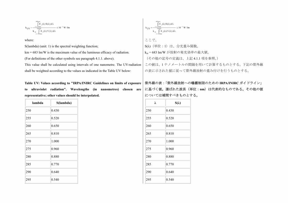
where:
S(lambda) (unit: 1) is the spectral weighting function;
km = 683 lm/W is the maximum value of the luminous efficacy of radiation.
(For definitions of the other symbols see paragraph 4.1.1. above).
This value shall be calculated using intervals of one nanometre. The UV-radiation
shall be weighted according to the values as indicated in the Table UV below:
ここで、
S(λ)(単位:1)は、分光重み関数。
km = 683 lm/W が放射の発光効率の最大値。
(その他の記号の定義は、上記 4.1.1 項を参照。)
この値は、1 ナノメートルの間隔を用いて計算するものとする。下記の紫外線
の表に示された値に従って紫外線放射の重み付けを行うものとする。
Table UV: Values according to "IRPA/INIRC Guidelines on limits of exposure
to ultraviolet radiation". Wavelengths (in nanometres) chosen are
representative; other values should be interpolated.
lambda S(lambda)
250 0.430
255 0.520
260 0.650
265 0.810
270 1.000
275 0.960
280 0.880
285 0.770
290 0.640
295 0.540
紫外線の表:「紫外線放射への曝露制限のための IRPA/INIRC ガイドライン」
に基づく値。選ばれた波長(単位:nm)は代表的なものである。その他の値
については補間すべきものとする。
λ S(λ)
250 0.430
255 0.520
260 0.650
265 0.810
270 1.000
275 0.960
280 0.880
285 0.770
290 0.640
295 0.540
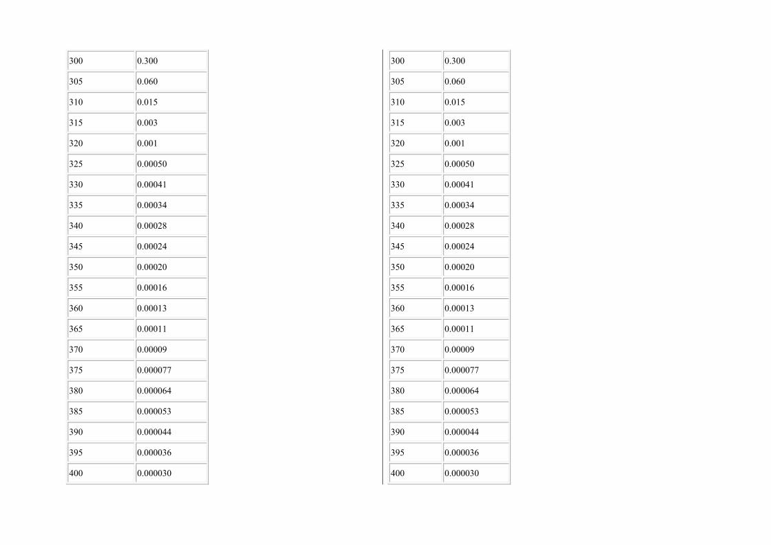
300 0.300
305 0.060
310 0.015
315 0.003
320 0.001
325 0.00050
330 0.00041
335 0.00034
340 0.00028
345 0.00024
350 0.00020
355 0.00016
360 0.00013
365 0.00011
370 0.00009
375 0.000077
380 0.000064
385 0.000053
390 0.000044
395 0.000036
400 0.000030
300 0.300
305 0.060
310 0.015
315 0.003
320 0.001
325 0.00050
330 0.00041
335 0.00034
340 0.00028
345 0.00024
350 0.00020
355 0.00016
360 0.00013
365 0.00011
370 0.00009
375 0.000077
380 0.000064
385 0.000053
390 0.000044
395 0.000036
400 0.000030
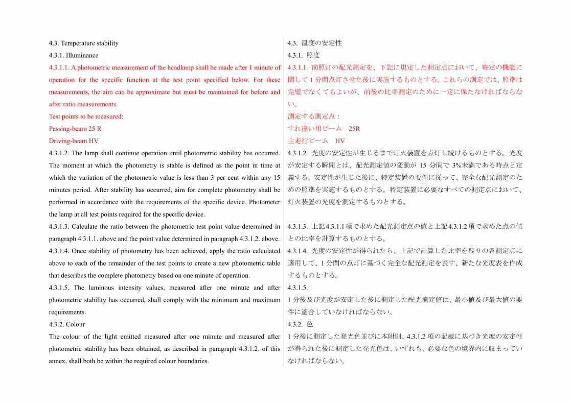
4.3. Temperature stability
4.3.1. Illuminance
4.3. 温度の安定性
4.3.1. 照度
4.3.1.1. A photometric measurement of the headlamp shall be made after 1 minute of
operation for the specific function at the test point specified below. For these
measurements, the aim can be approximate but must be maintained for before and
after ratio measurements.
Test points to be measured:
Passing-beam 25 R
Driving-beam HV
4.3.1.1. 前照灯の配光測定を、下記に規定した測定点において、特定の機能に
関して 1 分間点灯させた後に実施するものとする。これらの測定では、照準は
完璧でなくてもよいが、前後の比率測定のために一定に保たなければならな
い。
測定する測定点:
すれ違い用ビーム 25R
主走行ビーム HV
4.3.1.2. The lamp shall continue operation until photometric stability has occurred.
The moment at which the photometry is stable is defined as the point in time at
which the variation of the photometric value is less than 3 per cent within any 15
minutes period. After stability has occurred, aim for complete photometry shall be
performed in accordance with the requirements of the specific device. Photometer
the lamp at all test points required for the specific device.
4.3.1.2. 光度の安定性が生じるまで灯火装置を点灯し続けるものとする。光度
が安定する瞬間とは、配光測定値の変動が 15 分間で 3%未満である時点と定
義する。安定性が生じた後に、特定装置の要件に従って、完全な配光測定のた
めの照準を実施するものとする。特定装置に必要なすべての測定点において、
灯火装置の光度を測定するものとする。
4.3.1.3. Calculate the ratio between the photometric test point value determined in
paragraph 4.3.1.1. above and the point value determined in paragraph 4.3.1.2. above.
4.3.1.3. 上記4.3.1.1項で求めた配光測定点の値と上記4.3.1.2項で求めた点の値
との比率を計算するものとする。
4.3.1.4. Once stability of photometry has been achieved, apply the ratio calculated
above to each of the remainder of the test points to create a new photometric table
that describes the complete photometry based on one minute of operation.
4.3.1.4. 光度の安定性が得られたら、上記で計算した比率を残りの各測定点に
適用して、1 分間の点灯に基づく完全な配光測定を表す、新たな光度表を作成
するものとする。
4.3.1.5. The luminous intensity values, measured after one minute and after
photometric stability has occurred, shall comply with the minimum and maximum
requirements.
4.3.1.5.
1 分後及び光度が安定した後に測定した配光測定値は、最小値及び最大値の要
件に適合していなければならない。
4.3.2. Colour
The colour of the light emitted measured after one minute and measured after
photometric stability has been obtained, as described in paragraph 4.3.1.2. of this
annex, shall both be within the required colour boundaries.
4.3.2. 色
1 分後に測定した発光色並びに本附則、4.3.1.2 項の記載に基づき光度の安定性
が得られた後に測定した発光色は、いずれも、必要な色の境界内に収まってい
なければならない。
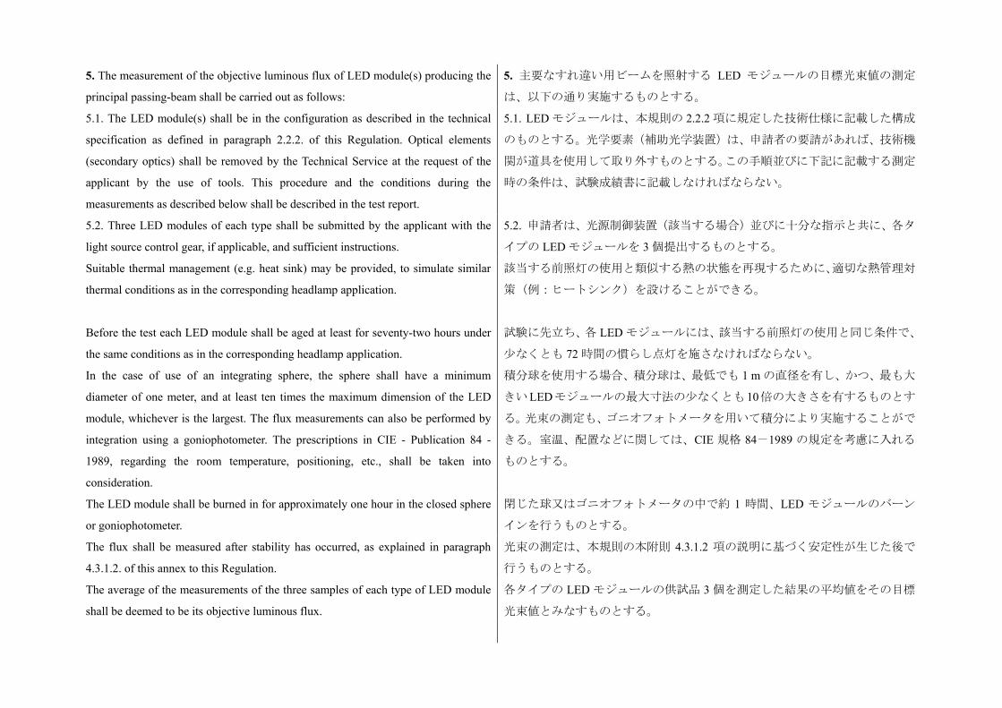
5. The measurement of the objective luminous flux of LED module(s) producing the
principal passing-beam shall be carried out as follows:
5. 主要なすれ違い用ビームを照射する LED モジュールの目標光束値の測定
は、以下の通り実施するものとする。
5.1. The LED module(s) shall be in the configuration as described in the technical
specification as defined in paragraph 2.2.2. of this Regulation. Optical elements
(secondary optics) shall be removed by the Technical Service at the request of the
applicant by the use of tools. This procedure and the conditions during the
measurements as described below shall be described in the test report.
5.1. LED モジュールは、本規則の 2.2.2 項に規定した技術仕様に記載した構成
のものとする。光学要素(補助光学装置)は、申請者の要請があれば、技術機
関が道具を使用して取り外すものとする。この手順並びに下記に記載する測定
時の条件は、試験成績書に記載しなければならない。
5.2. Three LED modules of each type shall be submitted by the applicant with the
light source control gear, if applicable, and sufficient instructions.
5.2. 申請者は、光源制御装置(該当する場合)並びに十分な指示と共に、各タ
イプの LED モジュールを 3 個提出するものとする。
Suitable thermal management (e.g. heat sink) may be provided, to simulate similar
thermal conditions as in the corresponding headlamp application.
該当する前照灯の使用と類似する熱の状態を再現するために、適切な熱管理対
策(例:ヒートシンク)を設けることができる。
Before the test each LED module shall be aged at least for seventy-two hours under
the same conditions as in the corresponding headlamp application.
試験に先立ち、各 LED モジュールには、該当する前照灯の使用と同じ条件で、
少なくとも 72 時間の慣らし点灯を施さなければならない。
In the case of use of an integrating sphere, the sphere shall have a minimum
diameter of one meter, and at least ten times the maximum dimension of the LED
module, whichever is the largest. The flux measurements can also be performed by
integration using a goniophotometer. The prescriptions in CIE - Publication 84 -
1989, regarding the room temperature, positioning, etc., shall be taken into
consideration.
積分球を使用する場合、積分球は、最低でも 1 m の直径を有し、かつ、最も大
きいLEDモジュールの最大寸法の少なくとも 10倍の大きさを有するものとす
る。光束の測定も、ゴニオフォトメータを用いて積分により実施することがで
きる。室温、配置などに関しては、CIE 規格 84-1989 の規定を考慮に入れる
ものとする。
The LED module shall be burned in for approximately one hour in the closed sphere
or goniophotometer.
閉じた球又はゴニオフォトメータの中で約 1 時間、LED モジュールのバーン
インを行うものとする。
The flux shall be measured after stability has occurred, as explained in paragraph
4.3.1.2. of this annex to this Regulation.
光束の測定は、本規則の本附則 4.3.1.2 項の説明に基づく安定性が生じた後で
行うものとする。
The average of the measurements of the three samples of each type of LED module
shall be deemed to be its objective luminous flux.
各タイプの LED モジュールの供試品 3 個を測定した結果の平均値をその目標
光束値とみなすものとする。
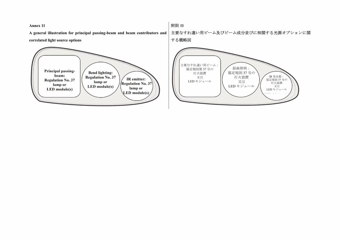
Annex 11
A general illustration for principal passing-beam and beam contributors and
correlated light source options
附則 11
主要なすれ違い用ビーム及びビーム成分並びに相関する光源オプションに関
する概略図
主要なすれ違い用ビーム:
協定規則第 37 号の 灯火装置
又は LED モジュール
屈曲照明:
協定規則 37 号の灯火装置 又は
LED モジュール
IR 発光器: 協定規則 37 号の
灯火装置 又は
LED モジュール